

Page 1
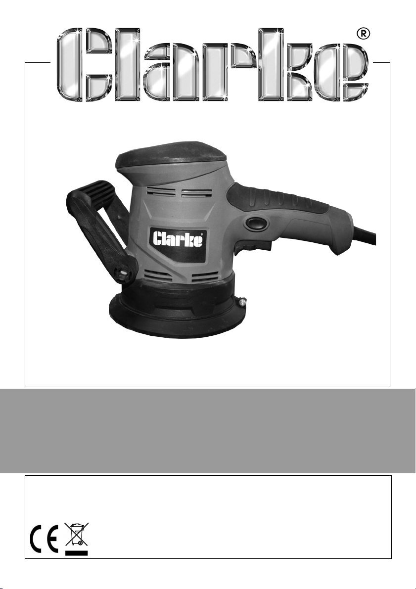
RANDOM ORBITAL SANDER
MODEL NO: CROS3
PART NO: 6462012
OPERATION & MAINTENANCE
INSTRUCTIONS
LS0616
Page 2
INTRODUCTION
Thank you for purchasing this CLARKE Sander, which is designed for DIY and
light workshop use only.
Read all safety warnings, instructions, illustrations and specifications provided
with this power tool. In doing so you will ensure the safety of yourself and that
of others around you, and you can look forward to your purchase giving you
long and satisfactory service. Failure to follow all instructions listed may result in
electric shock, fire and/or serious injury.
GUARANTEE
This product is guaranteed against faulty manufacture for a period of 12
months from the date of purchase. Please keep your receipt which will be
required as proof of purchase.
This guarantee is invalid if the product is found to have been abused or
tampered with in any way, or not used for the purpose for which it was
intended.
Faulty goods should be returned to their place of purchase, no product can
be returned to us without prior permission.
This guarantee does not effect your statutory rights.
SPECIFICATION
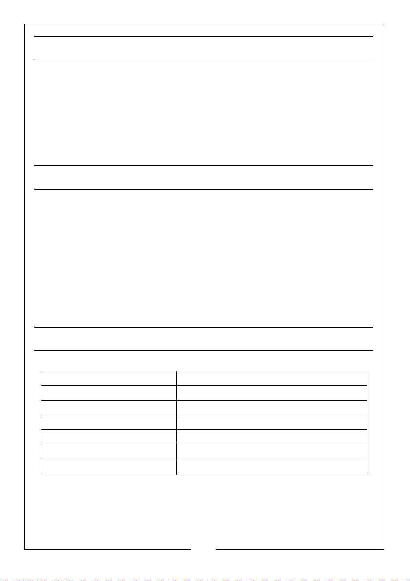
Electrical Supply 230V 50Hz 1 ph
Power rating 450 Watt
Fuse rating 5 Amp
No Load Speed (variable) 7000 - 14000 rpm
Net Weight 2.6 kg
Disc Size 125 mm
Vibration Emissions
Parts & Service: 020 8988 7400 / E-mail: [email protected] or [email protected]
4.596 m/s
2
/ uncertainty value (k) =1.5 m/s
2
2
Page 3

SAFETY PRECAUTIONS
WARNING: READ ALL INSTRUCTIONS. FAILURE TO FOLLOW ALL
INSTRUCTIONS LISTED BELOW MAY RESULT IN ELECTRIC SHOCK, FIRE AND/
OR SERIOUS INJURY. THE TERM “POWER TOOL” IN ALL WARNINGS LISTED
BELOW REFERS TO YOUR RANDOM ORBITAL SANDER.
1) WORK AREA SAFETY
a. Keep work area clean and well lit. Cluttered or dark areas invite accidents.
b. Do not operate power tools in explosive atmospheres, such as in the presence of
flammable liquids, gases or dust. Power tools create sparks which may ignite the
dust or fumes.
c. Keep children and bystanders away while operating a power tool. Distractions
can cause you to lose control.
2) ELECTRICAL SAFETY
a. Power tool plugs must match the power outlet. Never modify the plug in any
way. Do not use any adapter plugs with earthed (grounded) power tools.
Unmodified plugs and matching power outlets will reduce risk of electric shock.
b. Avoid body contact with earthed or grounded surfaces, such as pipes, radiators,
ranges and refrigerators. There is an increased risk of electric shock if your body is
earthed or grounded.
c. Do not expose power tools to rain or wet conditions. Water entering a power tool
will increase the risk of electric shock.
d. Do not abuse the cable. Never use the cable for carrying, pulling or unplugging
the power tool. Keep cable away from heat, oil, sharp edges or moving parts.
Damaged or entangled cables increase the risk of electric shock.
e. When operating a power tool outdoors, use an extension lead suitable for
outdoor use. Use of a cable suitable for outdoor use reduces the risk of electric
shock.
f. If operating a power tool in a damp location is unavoidable, use a residual
current device (RCD) protected supply. Use of an RCD reduces the risk of electric
shock.
3) PERSONAL SAFETY
a. Stay alert, watch what you are doing and use common sense when operating a
power tool. Do not use a power tool while you are tired or under the influence of
drugs, alcohol or medication. A moment of inattention while operating power
tools may result in serious personal injury.
b. Use personal protective equipment. Always wear eye protection. Protective
equipment such as dust mask, non-skid safety shoes, hard hat, or hearing
protection used for appropriate conditions will reduce personal injuries.
3
Parts & Service: 020 8988 7400 / E-mail: [email protected] or [email protected]
Page 4

c. Prevent unintentional starting. Ensure the trigger is in the off-position before
connecting to power source, picking up or carrying the tool. Carrying power
tools with your finger on the trigger or energising power tools that have the
switch on invites accidents.
d. Remove any adjusting key or wrench before turning the power tool on. A wrench
or a key left attached to a rotating part of the power tool may result in personal
injury.
e. Do not overreach. Keep proper footing and balance at all times. This enables
better control of the power tool in unexpected situations.
f. Dress properly. Do not wear loose clothing or jewellery. Keep your hair, clothing
and gloves away from moving parts. Loose clothes, jewellery or long hair can be
caught in moving parts.
g. If devices are provided for the connection of dust extraction and collection
facilities, ensure these are connected and properly used. Use of dust collection
can reduce dust-related hazards.
4) POWER TOOL USE AND CARE
a. Do not force the power tool. Use the correct power tool for your application. The
correct power tool will do the job better and safer at the rate for which it was
designed.
b. Do not use the power tool if the switch does not turn it on and off. Any power tool
that cannot be controlled with the switch is dangerous and must be repaired.
c. Disconnect the plug from the power source before making any adjustments,
changing accessories, or storing power tools. Such preventive safety measures
reduce the risk of starting the power tool accidentally.
d. Store idle power tools out of the reach of children and do not allow persons
unfamiliar with the power tool or these instructions to operate the power tool.
Power tools are dangerous in the hands of untrained users.
e. Maintain power tools. Check for misalignment or binding of moving parts,
breakage of parts and any other condition that may affect the power tool's
operation. If damaged, have the power tool repaired before use. Many
accidents are caused by poorly maintained power tools.
f. Keep cutting tools sharp and clean. Properly maintained cutting tools with sharp
cutting edges are less likely to bind and are easier to control.
g. Use the power tool, and accessories in accordance with these instructions,
taking into account the working conditions and the work to be performed. Use of
the power tool for operations different from those intended could result in a
hazardous situation.
5) SERVICE
a. Have your power tool serviced by a qualified repair person using only identical
replacement parts. This will ensure that the safety of the power tool is
maintained.
4
Parts & Service: 020 8988 7400 / E-mail: [email protected] or [email protected]
Page 5

SAFETY INSTRUCTIONS FOR KICKBACK
WARNING: KICKBACK IS A SUDDEN REACTION TO A PINCHED OR
SNAGGED ROTATING WHEEL, BACKING PAD, BRUSH OR ANY OTHER
ACCESSORY. PINCHING OR SNAGGING CAUSES RAPID STALLING OF THE
ROTATING ACCESSORY WHICH IN TURN CAUSES THE UNCONTROLLED
POWER TOOL TO BE FORCED IN THE DIRECTION OPPOSITE OF THE
ACCESSORY'S ROTATION AT THE POINT OF THE BINDING.
WARNING: KICKBACK IS THE RESULT OF POWER TOOL MISUSE AND/OR
INCORRECT OPERATING PROCEDURES OR CONDITIONS AND CAN BE
AVOIDED BY TAKING PROPER PRECAUTIONS AS GIVEN BELOW.
1. Maintain a firm grip on the power tool and position your body and arm to
allow you to resist kickback forces. Always use the auxiliary handle, if
provided, for maximum control over kickback or torque reaction during
start-up. The operator can control torque reactions or kickback forces, if
proper precautions are taken.
2. Never place your hand near the sanding pad. It may kickback over your
hand.
3. Do not position your body in the area where power tool will move if
kickback occurs. Kickback will propel the tool in the direction opposite to
the sanding pads movement at the point of snagging.
4. Use special care when working corners, sharp edges etc. Avoid bouncing
and snagging the sanding pad. Corners, sharp edges or bouncing have a
tendency to snag the rotating accessory and cause loss of control or
kickback.
5
Parts & Service: 020 8988 7400 / E-mail: [email protected] or [email protected]
Page 6
SAFETY SYMBOLS
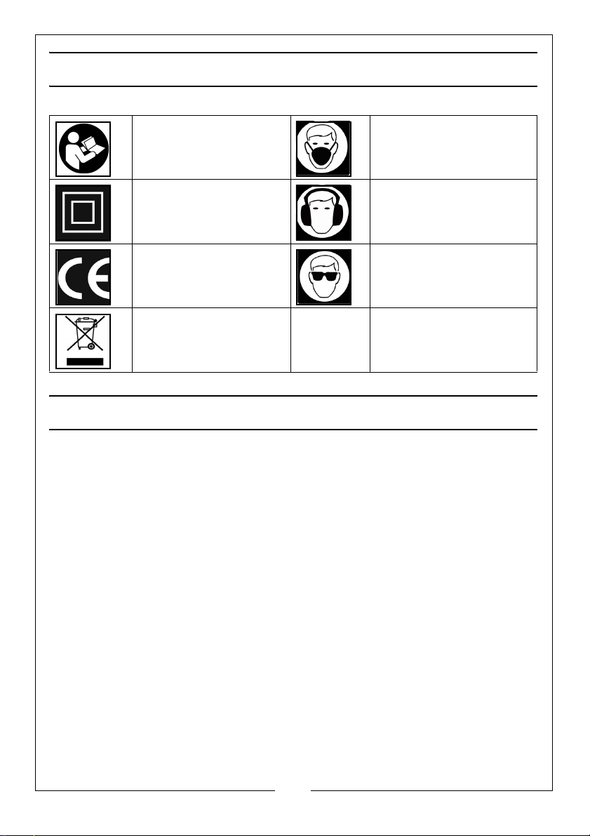
Read instruction
manual before use
Class 2 Double
Insulated
CE Mark Wear safety glasses
Weee Directive
Wear dust mask
Wear ear defenders
DUST EXTRACTION
The sander is provided with a dust extraction facility. Please note however,
that this does not preclude the user from wearing a face mask to prevent the
inhalation of dust particles.
6
Parts & Service: 020 8988 7400 / E-mail: [email protected] or [email protected]
Page 7
ELECTRICAL CONNECTIONS
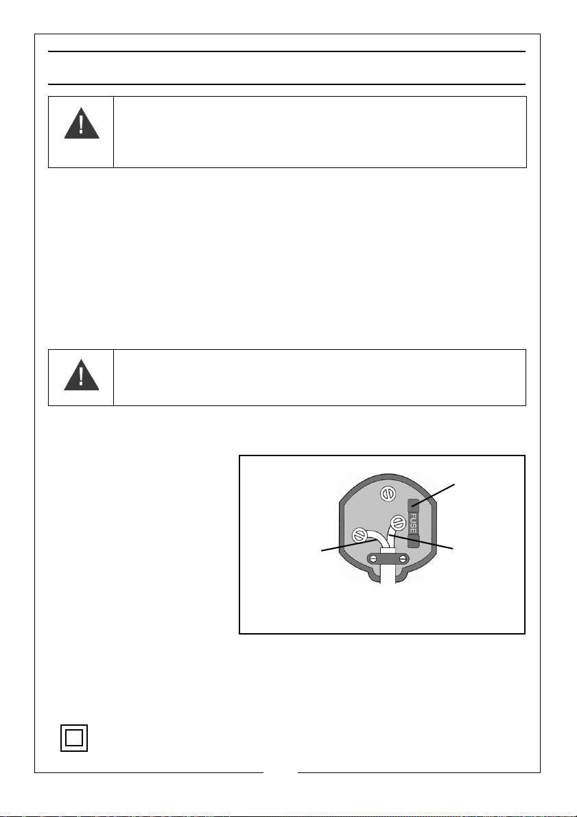
Plug must be BS1363/A approved.
Always fit
Ensure that the outer sheath of
Neutral
(Blue)
Live
(Brown)
a 5 Amp
the cable is firmly held by the clamp
fuse
WARNING: READ THESE ELECTRICAL SAFETY INSTRUCTIONS
THOROUGHLY BEFORE CONNECTING THE PRODUCT TO THE MAINS
SUPPLY.
Before switching the product on, make sure that the voltage of your electricity
supply is the same as that indicated on the rating plate. Connecting it to any
other power source may cause damage.
If it is necessary to change the fuse in the plug, the fuse cover must be refitted.
If the fuse cover becomes lost or damaged, the plug must not be used until a
suitable replacement is obtained.
If the plug has to be changed due to damage, a replacement should be
fitted, following the wiring instructions shown below. The old plug must be
disposed of as insertion into a mains socket could cause an electrical hazard.
WARNING: THE WIRES IN THE POWER CABLE OF THIS PRODUCT ARE
COLOURED IN ACCORDANCE WITH THE FOLLOWING CODE:
BLUE = NEUTRAL BROWN = LIVE
If the colours of the wires in the power cable of this product do not correspond
with the markings on the terminals of your plug, proceed as follows.
• The wire which is
coloured Blue must be
connected to the
terminal which is
marked N or coloured
Black.
• The wire which is
coloured Brown must
be connected to the
terminal which is
marked L or coloured
We strongly recommend that this machine is connected to the mains supply via
a Residual Current Device (RCD)
Red.
If in any doubt, consult a qualified electrician. DO NOT attempt any repairs
yourself.
This symbol indicates that this is a Class II product, and does not require
an earth connection.
Parts & Service: 020 8988 7400 / E-mail: [email protected] or [email protected]
7
Page 8
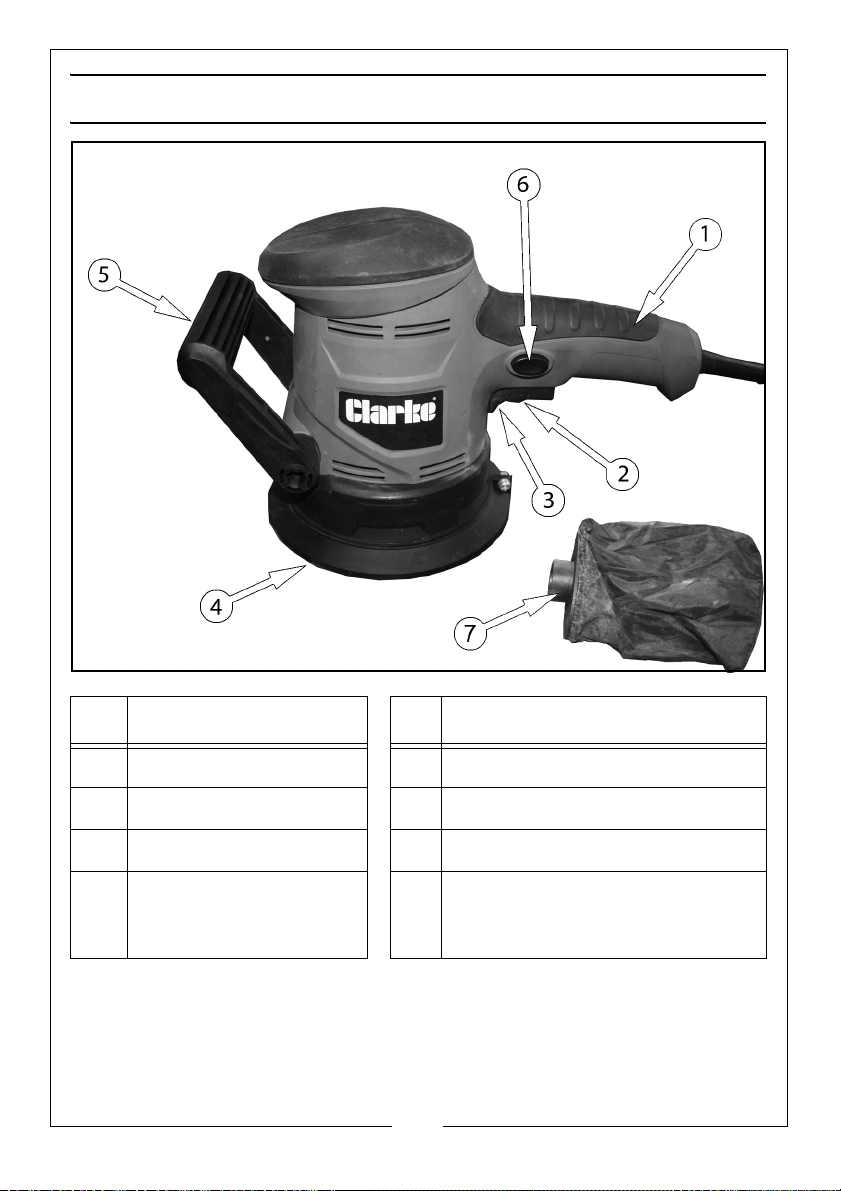
PRODUCT OVERVIEW
NO DESCRIPTION NO DESCRIPTION
1 Handle 5 Auxiliary Handle
2 Speed Control 6 Lock-On Button
3 Trigger 7 Dust Bag
4 Sanding Pad 8 2 x 60G sanding discs (not shown)
2 x 100G sanding discs (not shown)
1 x 150G sanding disc (not shown)
8
Parts & Service: 020 8988 7400 / E-mail: [email protected] or [email protected]
Page 9
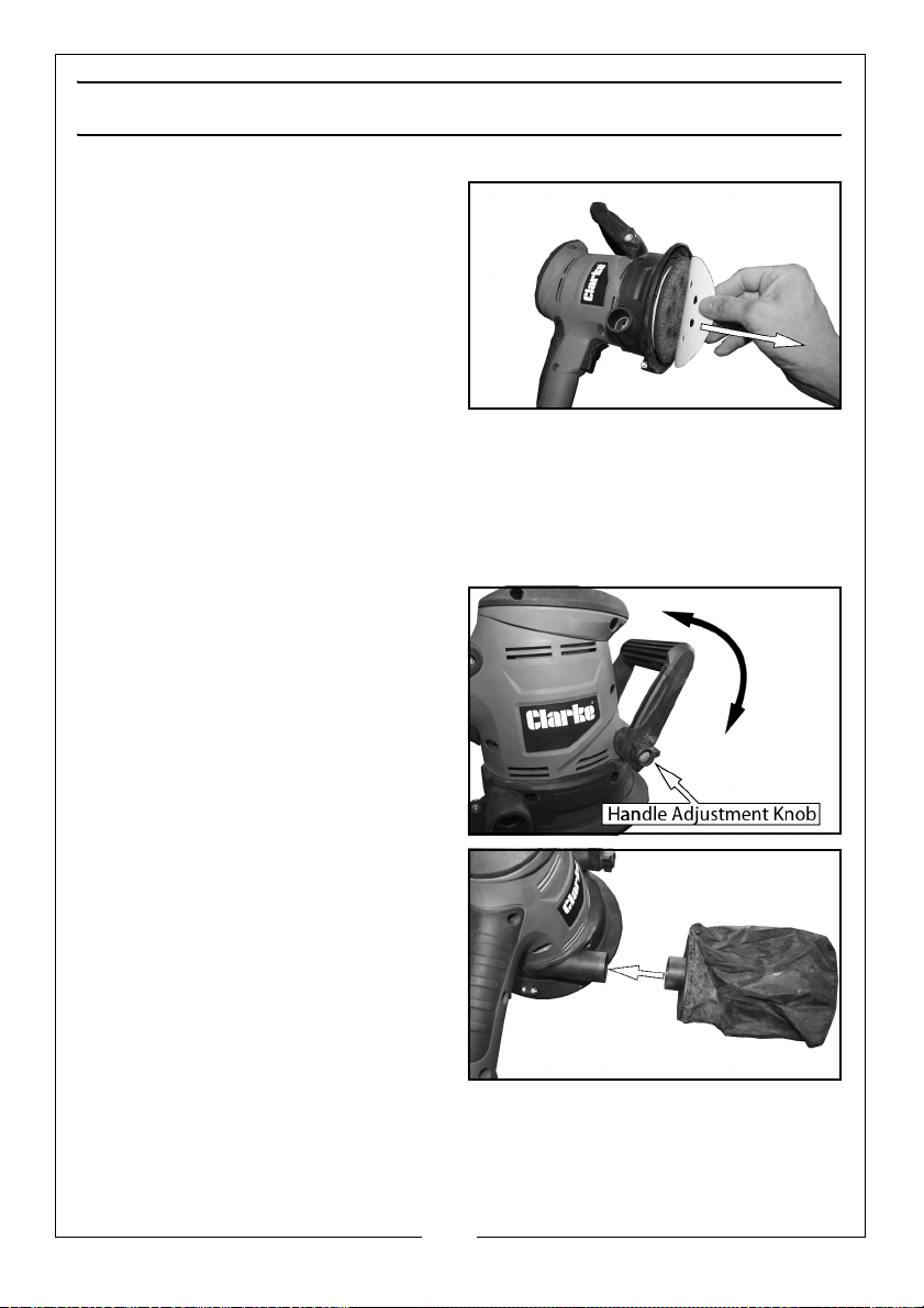
PREPARATION AND USE
FITTING A SANDING DISC
1. Select the disc to be used.
• This MUST be the correct
125mm diameter disc with
hook and loop backing.
2. Ensure the sander is switched off
and the plug is removed from the
socket.
3. Line up the holes in the disc with those on the sanding pad.
• This is necessary for dust extraction purposes.
4. Press the disc firmly onto the pad to secure it.
ADJUSTING THE AUXILIARY HANDLE
1. Loosen the handle adjustment
knob.
2. Adjust the handle to the required
position.
3. Retighten the handle adjustment
knob.
DUST COLLECTION
Slide the dust bag onto the outlet as
shown.
The dust bag must be emptied
regularly:- do not wait until it is
completely full.
The dust bag is emptied as follows.
1. Ensure the sander is not running.
2. Gently remove the dust bag assy
from the sander.
3. Take the dust bag to the dustbin and slip the bag off, (the bag has an
elasticated top), empty the bag into the bin.
4. Reassemble the dust bag assy and fit back on to the sander.
9
Parts & Service: 020 8988 7400 / E-mail: [email protected] or [email protected]
Page 10
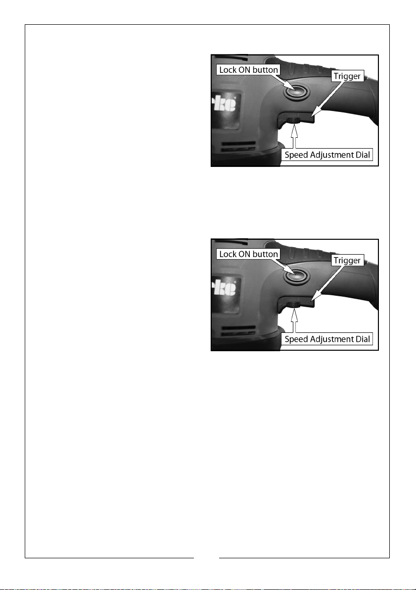
OPERATION
1. Plug into the mains socket and
switch on,
2. Place the sanding disc on the
workpiece.
• Hold the sander firmly with both
hands.
3. Squeeze the trigger.
• Work gently across the
workpiece until smooth.
4. Release the trigger.
• Wait until the motor has stopped fully before putting the sander
down.
SPEED CONTROL
To control the speed, turn the knob
located on the trigger in the direction
marked, i.e. - = lower speed + =
higher speed.
LOCK ON FEATURE
For continuous sanding:
1. Squeeze the trigger and then
press the LOCK ON button.
• The sander will continue to run
even if the trigger is released.
2. To release the lock on feature, Squeeze the trigger again.
10
Parts & Service: 020 8988 7400 / E-mail: [email protected] or [email protected]
Page 11
MAINTENANCE
• Always inspect the sander before use and ensure it is in top
condition.
• Ensure all air vents are clear. (Use vacuum cleaner to clean the
machine where possible).
• Check the power cable to ensure it is sound and free from cracks,
bare wires etc. Avoid using solvents when cleaning plastic parts,
(most plastics are susceptible to damage from the various types of
commercial solvents).
• All bearings etc., in this tool are lubricated with sufficient high grade
lubricant for the machine’s lifetime under normal operating
conditions, therefore no further lubrication is required.
REPLACEMENT DISCS
GRIT SIZE PART NUMBER
60 grit (pack of 5) 6463051
100 grit (pack of 5) 6463052
150 grit (pack of 5) 6463053
ENVIRONMENTAL RECYCLING POLICY
Through purchase of this product, the customer is taking on the
obligation to deal with the WEEE in accordance with the WEEE
regulations in relation to the treatment, recycling & recovery and
environmentally sound disposal of the WEEE.
In effect, this means that this product must not be disposed of with general
household waste. It must be disposed of according to the laws governing
Waste Electrical and Electronic Equipment (WEEE) at a recognised disposal
facility.
11
Parts & Service: 020 8988 7400 / E-mail: [email protected] or [email protected]
Page 12

TROUBLESHOOTING
PROBLEM CAUSE REMEDY
Sander is
overheating.
The machine is blocked
with dust.
Clean the ventilation holes.
Wipe the exterior with a dry cloth.
Excessive
Sparking.
Sander does
not operate
when
switched on.
Dust is not
extracted.
Worn brushes. This problem is easily remedied but
you should consult your CLARKE
dealer for parts and advice.
Check to ensure the fuse
in the plug is sound.
The dust bag is full or the
dust extractor flue is
blocked.
If the fuse is sound or blows
repeatedly, consult your CLARKE
dealer.
Remove and empty the bag, also
clear any blockage.
12
Parts & Service: 020 8988 7400 / E-mail: [email protected] or [email protected]
Page 13
Page 14
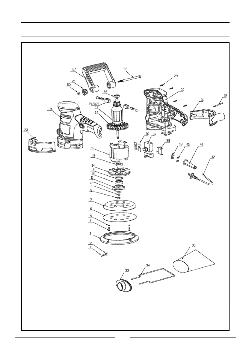
PARTS LIST
ID DESCRIPTION ID DESCRIPTION
Screw
01
Nut
02
Dust Collection Circle
03
Self-tapping Screw
04
Spring Washer
05
Sanding Paper
06
Foam Sanding Pad
07
Nut
08
Spring Washer
09
Washer
10
Bearing Cover
11
Bearing
12
Lock Spring
13
Aluminum Fan
14
Bearing
15
Stator
16
Fan
17
Rotor
18
Carbon Brush Holder
19
Carbon Brush
20
Carbon Brush Cover
21
Bearing
22
Partial Cover Of Left Housing
23
Left Housing
24
Nut
25
Handle Adjument Knob
26
Adjustable Handle
27
Hex Bolt
28
Self-tapping Screw
29
Right Housing
30
Partial Cover Of Right Housing
31
Self Tapping Screw
32
Dust Collection Sleeve
33
Steel Frame Of Dust Collection Bag
34
Dust Collection Bag
35
Inductor
36
Switch
37
Capacitor
38
Strain Relief
39
Self-tapping Screw
40
Cable Sleeve
41
Cable
42
When requesting spare parts, please quote the reference WGCROS3 followed by
the number listed.
14
Parts & Service: 020 8988 7400 / E-mail: [email protected] or [email protected]
Page 15
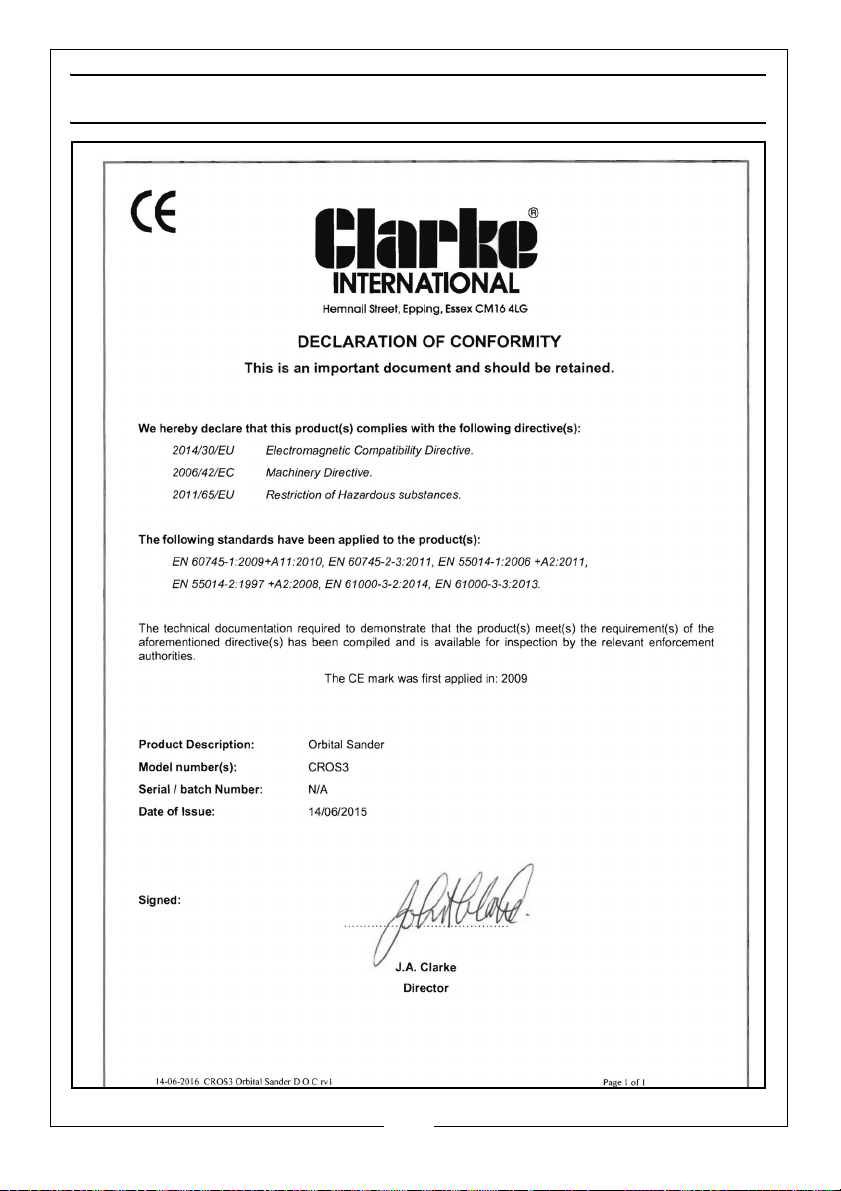
DECLARATION OF CONFORMITY
15
Parts & Service: 020 8988 7400 / E-mail: [email protected] or [email protected]
Page 16
 Loading...