

Page 1

10”SLIDING MITRE SAW
MODEL NO: CMS10S2
PART NO: 6461514
OPERATION & MAINTENANCE
INSTRUCTIONS
ORIGINAL INSTRUCTIONS
LS1217 - ISS 5
Page 2
INTRODUCTION
Thank you for purchasing this CLARKE 10”Sliding Mitre Saw.
Before attempting to use this product, please read this manual thoroughly and
follow the instructions carefully. In doing so you will ensure the safety of yourself
and that of others around you, and you can look forward to your purchase
giving you long and satisfactory service.
IMPORTANT
Please read all of the safety and operating instructions carefully before using this
product. Please pay particular attention to all sections of this User Guide that
display warning symbols and notices.
WARNING! This is a Warning symbol. This symbol is used
throughout the user guide whenever there is a risk of personal
injury. Ensure that these warnings are read and understood at all
times.
CAUTION! This is a Caution symbol. This symbol is used
throughout the user guide whenever there is a risk of damaging
your product. Ensure that these cautions are read and understood
at all times.
GUARANTEE
This product is guaranteed against faulty manufacture for a period of 12
months from the date of purchase. Please keep your receipt which will be
required as proof of purchase.
This guarantee is invalid if the product is found to have been abused or
tampered with in any way, or not used for the purpose for which it was
intended.
Faulty goods should be returned to their place of purchase, no product can
be returned to us without prior permission.
This guarantee does not effect your statutory rights.
2
Parts & Service: 020 8988 7400 / E-mail: [email protected] or [email protected]
Page 3

TABLE OF CONTENTS
INTRODUCTION ..........................................................................2
IMPORTANT ................................................................................2
GUARANTEE ...............................................................................2
TABLE OF CONTENTS ..................................................................3
GENERAL SAFETY RULES .............................................................4
ADDITIONAL SAFETY RULES FOR MITRE SAWS ..........................5
SAFETY SYMBOLS .......................................................................7
ELECTRICAL CONNECTIONS .....................................................8
OVERVIEW ..................................................................................9
BEFORE USE ................................................................................10
Bench mounting ..............................................................................10
Locking / Releasing the saw head ................................................ 11
Fitting the work clamp .................................................................... 11
Fitting work supports ........................................................................ 12
Dust extraction .................................................................................12
INSTRUCTIONS FOR USE .............................................................13
Body and hand position ................................................................. 13
Switching on and off .......................................................................13
BASIC SAW CUTS .......................................................................14
Vertical straight cross cut ...............................................................14
Performing a sliding cut .................................................................. 15
Mitre cross-cut ..................................................................................15
Bevel cuts .........................................................................................16
Mitre / Bevel Cuts ............................................................................16
Compound mitre cuts ....................................................................16
Groove cutting ................................................................................17
Transporting ......................................................................................18
THE LASER GUIDE .......................................................................18
ADJUSTMENTS ............................................................................19
Checking and adjusting the mitre settings ..................................19
Checking and adjusting the bevel settings .................................20
MAINTENANCE ..........................................................................22
Changing the saw blade ............................................................... 22
Changing the carbon brushes ......................................................23
Cleaning ...........................................................................................23
ENVIRONMENTAL PROTECTION ................................................23
SPECIFICATIONS ........................................................................24
EXPLODED DIAGRAM ................................................................25
PARTS LIST ...................................................................................26
DECLARATION OF CONFORMITY ..............................................27
3
Parts & Service: 020 8988 7400 / E-mail: [email protected] or [email protected]
Page 4

GENERAL SAFETY RULES
WORK AREA
1. Keep the work area clean and
well lit. Cluttered and dark areas
invite accidents.
2. Do not operate power tools in
explosive atmospheres, such as in
the presence of flammable
liquids, gases or dust. Power tools
create sparks which may ignite
the dust or fumes.
3. Keep children and bystanders
away while operating a power
tool. Distractions can cause you
to lose control.
ELECTRICAL SAFETY
1. Power tool plugs must match the
outlet. Never modify the plug in
any way. Do not use adapter
plugs with earthed (grounded)
power tools. Unmodified plugs
and matching outlets will reduce
the risk of electric shock.
2. Do not expose power tools to rain
or wet conditions. Water entering
a power tool will increase the risk
of electric shock.
3. Do not abuse the cord. Never use
the cord for carrying, pulling or
unplugging the power tool. Keep
the cord away from heat, oil,
sharp edges or moving parts.
Damaged or entangled cords
increase the risk of electric shock.
4. When operating a power tool
outdoors, use an extension cord
suitable for outdoor use. Use of a
cord suitable for outdoor use
reduces the risk of electric shock.
5. If operating the power tool in a
damp location is unavoidable,
use a residual current device
(RCD) protected supply.
PERSONAL SAFETY
1. Stay alert, watch what you are
doing and use common sense
when operating a power tool. Do
not use a power tool while you
are tired or under the influence of
drugs, alcohol or medication. A
moment of inattention while
operating power tools may result
in personal injury.
2. Use safety equipment. Always
wear eye protection. Safety
equipment such as dust mask,
non-skid safety shoes, hard hat, or
hearing protection used for
appropriate conditions will
reduce personal injuries.
3. Avoid accidental starting. Ensure
the switch is in the off position
before plugging in. Carrying
power tools with your finger on
the switch or plugging in power
tools that have the switch on
invites accidents.
4. Remove any adjusting key or
wrench before turning the power
tool on. A wrench or a key left
attached to a rotating part of the
power tool may result in personal
injury.
5. Do not overreach. Keep proper
footing and balance at all times.
This enables better control of the
power tool in unexpected
situations.
4
Parts & Service: 020 8988 7400 / E-mail: [email protected] or [email protected]
Page 5

GENERAL SAFETY RULES
6. Dress properly. Do not wear loose
clothing or jewellery. Keep your
hair, clothing and gloves away
from moving parts. Loose clothes,
jewellery or long hair can be
caught in moving parts.
7. A laser beam can cause serious
eye injury. Never look into the
laser outlet.
POWER TOOL USE AND CARE
1. Do not force the power tool. Use
the correct power tool for your
application. The correct power
tool will do the job better and
safer at the rate which it was
designed.
2. Do not use the power tool if the
switch does not turn it on and off.
Any power tool that cannot be
controlled with the switch is
dangerous and must be repaired.
3. Disconnect the plug from the
power source before making any
adjustments, changing
accessories, or storing power
tools. Such preventive safety
measures reduce the risk of
starting the power tool
accidentally.
4. Store idle tools out of the reach of
children and do not allow persons
unfamiliar with the power tool or
these instructions to operate the
power tool. Power tools are
dangerous in the hands of
untrained users.
5. Maintain power tools. Check for
misalignment or binding of
moving parts, breakage of parts
and any other condition that may
affect the power tools operation.
If damaged, have the power tool
repaired before use. Many
accidents are caused by poorly
maintained power tools.
6. Keep cutting tools sharp and
clean. Tools with sharp cutting
edges are less likely to bind and
are easier to control.
7. Use the power tool and
accessories in accordance with
these instructions and in the
manner intended, taking into
account the working conditions
and the work to be performed.
Use of the power tool for
operations different from
intended use could result in a
hazardous situation.
ADDITIONAL SAFETY RULES FOR MITRE SAWS
1. Make sure all locking knobs and
clamp handles are tight before
starting any operation.
2. Do not operate the machine
without the guard in position, if
the guard does not function
correctly or is not maintained
properly.
3. Never use your saw without the
kerf plate.
4. Never place either hand in the
blade area when the saw is
connected to the electrical
power source.
5
Parts & Service: 020 8988 7400 / E-mail: [email protected] or [email protected]
Page 6

ADDITIONAL SAFETY RULES FOR MITRE SAWS
5. Never attempt to stop a machine
in motion rapidly by jamming a
tool or other means against the
blade; serious accidents can be
caused unintentionally in this way.
6. Before using any accessory
consult the instruction manual.
The improper use of an accessory
can cause damage.
7. Observe the maximum speed
marked on the saw blade.
8. Always wear gloves when
handling a saw blade.
9. Do not use blades of larger or
smaller diameter than
recommended. For the proper
blade rating refer to the technical
data. Use only the blades
specified in the specifications
section of this manual.
10. Do not use cracked or damaged
saw blades.
11. Do not use any abrasive discs.
12. Raise the blade from the kerf in
the workpiece prior to releasing
the switch.
13. Ensure that the arm is securely
fixed when performing bevel cuts.
14. The blade guard on your saw will
automatically raise when the arm
is brought down; it will lower over
the blade when the arm is raised.
The guard can be raised by hand
when installing or removing saw
blades or for inspection of the
saw. Never raise the blade guard
manually unless the saw is
switched off.
15. Keep the surrounding area of the
machine well maintained and
free of loose materials, e.g. chips
and cut-offs.
16. Before use, check that the motor
air slots are clean and free of
chips.
17. Replace the kerf plate when
worn.
18. Disconnect the machine from the
mains before carrying out any
maintenance work or when
changing the blade.
19. Never perform any cleaning or
maintenance work when the
machine is still running and the
head is not in the rest position.
20. When possible, always mount the
machine on to a bench or
plywood base which is then
clamped to a bench, or mount
the machine to a purpose built
mitre saw stand available from
your local Clarke dealer.
6
Parts & Service: 020 8988 7400 / E-mail: [email protected] or [email protected]
Page 7
SAFETY SYMBOLS
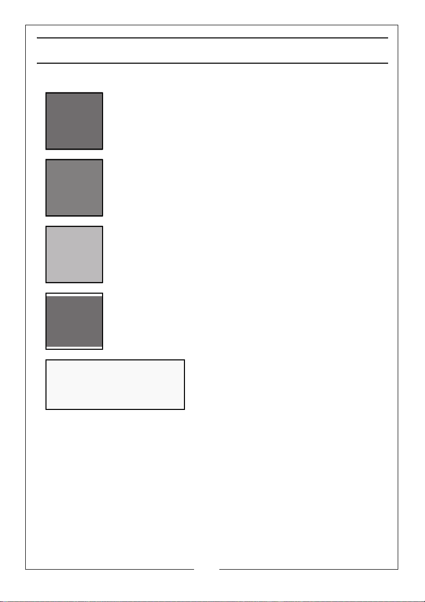
Wear eye protection
Wear ear defenders
Do not put your hand near the blade
Read instruction manual before use
Laser Radiation, Class 2 Laser: Do not stare
into the beam.
7
Parts & Service: 020 8988 7400 / E-mail: [email protected] or [email protected]
Page 8
ELECTRICAL CONNECTIONS
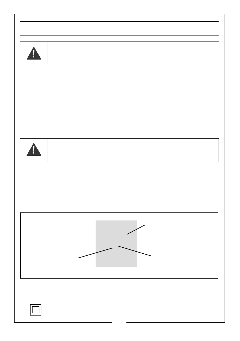
Plug must be BS1363/A approved.
Always fit a 13 Amp fuse.
Ensure that the outer sheath of the cable is firmly held by the clamp
Neutral
(Blue)
Live
(Brown)
WARNING! Read these electrical safety instructions thoroughly
before connecting the product to the mains supply.
Before switching the product on, make sure that the voltage of your electricity supply is
the same as that indicated on the rating plate. This product is designed to operate on
230VAC 50Hz. Connecting it to any other power source may cause damage.
This product may be fitted with a non-rewireable plug. If it is necessary to change the
fuse in the plug, the fuse cover must be refitted. If the fuse cover becomes lost or
damaged, the plug must not be used until a suitable replacement is obtained.
If the plug has to be changed because it is not suitable for your socket, or due to
damage, it should be cut off and a replacement fitted, following the wiring instructions
shown below. The old plug must be disposed of safely, as insertion into a mains socket
could cause an electrical hazard.
WARNING! The wires in the power cable of this product are
coloured in accordance with the following code:
Blue = Neutral Brown = Live
If the colours of the wires in the power cable of this product do not correspond with the
markings on the terminals of your plug, proceed as follows.
• The wire which is coloured Blue must be connected to the terminal which is
marked N or coloured Black.
• The wire which is coloured Brown must be connected to the terminal which is
marked L or coloured Red.
We strongly recommend that this machine is connected to the mains supply via a
Residual Current Device (RCD)
If in any doubt, consult a qualified electrician. DO NOT attempt any repairs yourself.
This symbol indicates that this is a Class II product, and does not require an
earth connection.
Parts & Service: 020 8988 7400 / E-mail: [email protected] or [email protected]
8
Page 9

Page 10
BEFORE USE
1. Remove the saw from the packing material carefully.
• The following should be supplied. If anything is missing contact your
dealer.
Cross-Cut Mitre Saw with Laser Guide 2 AAA Batteries (for laser guide)
Work Clamp Spare Pair of Carbon Brushes
2 x Work Supports Shavings / Dust Collection Bag
254 mm Diameter 60 Tooth TCT Wood
Cutting Blade
Combined 6 mm Hexagon Key and
Cross Head Screwdriver
BENCH MOUNTING
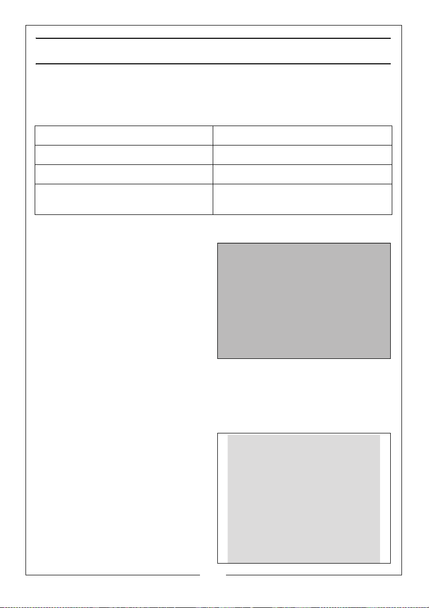
Holes are provided in all four feet to
facilitate bench mounting.
• Always mount your saw firmly
on a level surface to prevent
movement.
The tool can also be mounted to a
piece of 12.5 mm or thicker plywood
which can then be clamped to your
work support or moved to other job
sites and re-clamped when required.
• When mounting your saw to a piece of plywood, make sure that the
mounting screws do not protrude from the bottom of the wood.
• If the saw rocks on the surface, place a thin piece of material under one
saw foot until the saw is firm on the mounting surface.
MITRE SAW STAND (NOT SUPPLIED)
You can also mount the machine to
a purpose built mitre saw stand
available from your local Clarke
dealer.
10
Parts & Service: 020 8988 7400 / E-mail: [email protected] or [email protected]
Page 11
LOCKING / RELEASING THE SAW HEAD
1. Press down slightly on the
operating handle and pull out the
Head Lock Pin, and rotate it 90
degrees as shown.
2. Gently release the downward
pressure on the operating handle
and allow the head to rise to its
full height.
FITTING THE WORK CLAMP
1. Loosen the thumb screw on either
of the clamp supports.
2. Slide the work clamp into the
clamp supports.
3. Tighten the thumb screw to
secure the work clamp.
11
Parts & Service: 020 8988 7400 / E-mail: [email protected] or [email protected]
Page 12

FITTING WORK SUPPORTS
1. Loosen the work support securing
screw.
2. Slide the work supports into place
as shown.
3. Secure them in place by
tightening the work support
securing screw.
DUST EXTRACTION
This machine is provided with a dust
extraction point for connection to a
dust bag (supplied).
1. Place the dust bag over the dust
extraction port using the clip on
the neck of the dust bag.
2. Make sure the zipper on the dust
bag is closed.
3. The dust extraction port may also
be connected to a suitable
extraction system,using the appropriate hose (not supplied)
• The hose must have an inside diameter of 32 mm.
12
Parts & Service: 020 8988 7400 / E-mail: [email protected] or [email protected]
Page 13
INSTRUCTIONS FOR USE
Always observe the safety instructions and applicable regulations.
BODY AND HAND POSITION
Proper positioning of your body and hands when operating the mitre saw will
make cutting easier and safer.
• Never place your hands near the cutting area or blade.
• Hold the workpiece tightly to the table and the fence when cutting.
• Keep your hands in position until the trigger switch has been released
and the blade has completely stopped.
• Always make dry runs (without power) before cuts so that you can
check the path of the blade.
• Do not cross your hands.
SWITCHING ON AND OFF
1. To start the saw, squeeze the
trigger switch.
• Allow the motor to reach full
speed before cutting.
2. To stop the saw, release the
trigger switch.
WARNING: THE BLADE WILL CONTINUE TO ROTATE AFTER THE SWITCH HAS
BEEN RELEASED.
13
Parts & Service: 020 8988 7400 / E-mail: [email protected] or [email protected]
Page 14
BASIC SAW CUTS
VERTICAL STRAIGHT CROSS CUT
1. Release the table mitre lock and
move the arm to the 0° position
and re-tighten the table mitre
lock.
2. Release the slide rail lock, and
push the saw head back to the
rear position.
3. Retighten the slide rail lock.
4. Place the wood to be cut against
the fence.
5. Take hold of the operating handle
and press and hold the blade
guard release lever (1) to release
the head.
6. Squeeze the trigger switch (2) to
start the saw.
7. Lower the head allowing the
blade to cut through the timber
and enter the kerf plate.
• Allow the blade to cut freely.
Do not force the tool.
8. After completing the cut, release
the trigger and return the head to
its upper rest position.
14
Parts & Service: 020 8988 7400 / E-mail: [email protected] or [email protected]
Page 15

PERFORMING A SLIDING CUT
The guide rail allows cutting larger workpieces up to 340 mm x 78 mm using an
out-down-back sliding motion.
1. Release the slide rail lock.
2. Pull the saw head towards you (1)
and switch the saw on as
mentioned on the previous page.
3. Lower the saw blade (2) into the
workpiece and push the head
back (3) to complete the cut.
• Do not perform sliding cuts on
workpieces smaller than 50 x
100 mm.
• Remember to lock the saw
head in the rear position when
the sliding cuts are finished.
MITRE CROSS-CUT
1. Release the table mitre lock and
move the arm left or right to the
required angle.
2. Lock in position by tightening the
table mitre lock.
• Always ensure that the table
mitre lock is securely tightened
before cutting.
• Allow the blade to cut freely.
Do not force the tool.
• Proceed as for a vertical straight cross-cut.
NOTE: When mitering the end of a piece of wood with a small off-cut, position
the wood to ensure that the off-cut is to the side of the blade with the
greater angle to the fence; i.e. left mitre, offcut to the right - right mitre,
off-cut to the left.
15
Parts & Service: 020 8988 7400 / E-mail: [email protected] or [email protected]
Page 16
BEVEL CUTS
Bevel angles can be set from 45° left to vertical and can be cut with the mitre
arm set between zero and a maximum of 45° mitre position right or left.
1. Loosen the bevel adjustment
handle and set the bevel at the
desired angle.
2. Tighten the bevel adjustment
handle firmly.
3. Proceed as for a vertical straight
cross-cut.
• Allow the blade to cut freely.
Do not force the tool.
MITRE / BEVEL CUTS
As the number of sides changes, so do the mitre and bevel angles. The chart
below gives the cutting angles for a variety of shapes, assuming that all sides
are of equal length.
No. of sides Angle mitre or bevel
4 45°
5 36°
6 30°
7 25.7°
8 22.5°
9 20°
10 18°
COMPOUND MITRE CUTS
A compound mitre is a cut made using a mitre angle and a bevel angle at the
same time. This is the type of cut used to make frames or boxes with slanting
sides.
1. Set your saw to the required
angles and make a few trial cuts.
2. Practice fitting the cut pieces
together.
3. Always try cuts on a few scrap
pieces of wood to verify the
settings on the saw.
16
Parts & Service: 020 8988 7400 / E-mail: [email protected] or [email protected]
Page 17
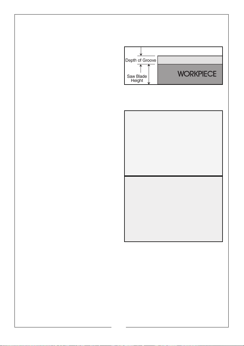
GROOVE CUTTING
Your saw is equipped with a grooving stop and thumbscrew to allow for
groove cutting.
1. Firstly, determine the depth of
your groove, and subtract this
value from the thickness of your
workpiece. This will give you the
height above the table surface at
which the saw blade must be set.
2. Ideally, place a template or a
piece of wood, the same thickness as the saw blade height setting, on the
table, beneath the saw blade.
3. Pivot the groove plate to the side
position shown.
4. Undo the adjuster locking ring (2)
and screw out the adjuster (1),
then lower the head so that it
lightly touches the template or is
at the correct height as
determined using a rule.
5. Screw down the adjuster (1) so
that it touches the groove plate
(3), then finally tighten the locking
ring (2).
• The saw blade is now set to cut
your groove, using the sliding
feature.
• The width of the groove will, of
course, be the width of the saw
blade. However, by moving the
workpiece along the table in small increments, each time making a cut,
it is possible to cut grooves to any desired width.
• Angled grooves may be cut by tilting the head to the appropriate
angle.
6. Before reverting to normal cutting, remember to turn the groove plate to its
normal position as shown.
17
Parts & Service: 020 8988 7400 / E-mail: [email protected] or [email protected]
Page 18

TRANSPORTING
1. Lower the head and lock it down
using the head lock pin.
2. Slide the head towards you and
secure in place using the slide rail
lock.
3. Lock the mitre arm with the table
mitre lock.
4. Lock the bevel adjustment handle
with the saw head in the vertical
position to make the tool as
compact as possible.
5. Always lift the saw using the lifting handle.
THE LASER GUIDE
Your saw is fitted with a laser guide to assist with accurate cutting.
INSERTING THE BATTERIES
1. Remove the battery cover.
2. Insert 2 x AAA batteries taking
care to follow the polarity
diagram inside the battery
compartment.
3. Replace the battery cover
SWITCHING ON/OFF
Switch the laser on/off using the on/
off switch.
18
Parts & Service: 020 8988 7400 / E-mail: [email protected] or [email protected]
Page 19
ADJUSTMENTS
WARNING: MAKE SURE THAT THE SAW IS SWITCHED OFF AND UNPLUGGED
FROM THE MAINS SUPPLY BEFORE PERFORMING ANY ADJUSTMENTS.
CHECKING AND ADJUSTING THE MITRE SETTINGS
1. Release the blade guard release
lever to release the mitre arm.
2. Lower the head until the blade
just enters the kerf plate.
3. Place a set square against the left
side of the fence and blade.
Move the mitre arm if required
until the blade is perfectly square
to the fence.
4. If pointer does not indicate zero
on the mitre scale, loosen the
screw that secures the pointer
and move the pointer as
necessary.
19
Parts & Service: 020 8988 7400 / E-mail: [email protected] or [email protected]
Page 20
CHECKING AND ADJUSTING THE BEVEL SETTINGS
1. Loosen the bevel clamp handle.
2. Press the saw head to the right to
ensure it is fully vertical and
tighten the bevel clamp handle.
3. Pull down the head until the
blade just enters the kerf plate.
90 DEGREE STOP ADJUSTMENT
4. Place a set square on the table
and up against the blade.
NOTE: Do not touch the tips of the
blade teeth with the square.
If adjustment is required, proceed as
follows:
5. Turn the 90° adjustment stop
screw in or out until the blade is at
90° to the table as shown by the
set square.
6. If the bevel pointer does not
indicate zero on the bevel scale,
loosen the screw that secures the
pointer and move the pointer as
necessary.
20
Parts & Service: 020 8988 7400 / E-mail: [email protected] or [email protected]
Page 21

45 DEGREE STOP ADJUSTMENT
1. Loosen the bevel clamp handle
and set the saw head as far to the
left as possible (this should be the
45° angle)
2. Place a 45° set square on the
table and up against the blade.
NOTE: Do not touch the tips of the
blade teeth with the square.
3. Turn the 45° adjustment stop screw in or out until the blade is at 45° to the
table as measured with the square.
4. Adjust the bevel point if required as shown in point 6 above.
21
Parts & Service: 020 8988 7400 / E-mail: [email protected] or [email protected]
Page 22
MAINTENANCE
WARNING: MAKE SURE THAT THE SAW IS SWITCHED OFF AND UNPLUGGED
FROM THE MAINS SUPPLY BEFORE FITTING OR REMOVING THE BLADE.
WARNING: THE BLADE MUST BE RATED TO AT LEAST 6000 RPM.
CHANGING THE SAW BLADE
Install the appropriate saw blade. Do not use excessively worn blades. The
maximum rotation speed of the tool must not exceed that of the saw blade.
1. With the saw head in the raised
position and with the slide rails
locked, move the blade guard
release to allow the blade guard
to be rotated back as shown.
• The centre screw should be
visible through the cut-out in
the guard.
2. Push and hold down the blade
lock, then using the Hex. wrench supplied, undo and remove the centre
screw.
• The screw has a LEFT HAND THREAD (turn it CLOCKWISE to undo).
WARNING: NEVER PUSH THE BLADE LOCK IN WHEN THE MOTOR IS
RUNNING.
3. Pull off the outer flange (marked with an ‘O’) followed by the saw blade.
NOTE: You should take this opportunity to thoroughly clean parts previously
inaccessible.
4. Replace the blade, ensuring it has the correct diameter and bore.
• Ensure also that all parts are perfectly clean and the blades’ teeth
point down at the front as shown in the picture above.
• The blade must be rated to at least 6000 rpm.
• Please note that spare blades are available from Clarke
International. Please see your Clarke dealer.
5. Replace the outer flange (marked with an ‘O’) and screw in the centre
screw, remembering the screw has a LEFT HAND THREAD (turn it
ANTICLOCKWISE to tighten).
22
Parts & Service: 020 8988 7400 / E-mail: [email protected] or [email protected]
Page 23

CHANGING THE CARBON BRUSHES
WARNING: MAKE SURE THAT THE SAW IS SWITCHED OFF AND UNPLUGGED
FROM THE MAINS SUPPLY BEFORE CHANGING THE CARBON BRUSHES.
A spare pair of carbon brushes are supplied with the machine. Should it
become necessary to change these:
1. Unscrew the brush holder plug.
2. Pull out the worn brushes.
3. Replace with new brushes.
4. Replace the brush holder plug,
taking care not to cross thread it.
CLEANING
Your power tool has been designed to operate over a long period of time with
a minimum of maintenance. Continuous satisfactory operation depends upon
proper tool care and regular cleaning.
• Keep the ventilation slots clear and regularly clean the motor
housing with a soft cloth.
• Regularly clean the table top.
• Regularly clean the dust collection bag.
• Avoid the use of cleaners or lubricants to maintain the tool. In
particular spray and aerosol cleaners may chemically attack the
plastic lower guard.
ENVIRONMENTAL PROTECTION
Recycle unwanted materials instead of disposing of them as
waste. All tools, accessories and packaging should be sorted,
taken to a recycling centre and disposed of in a manner which is
compatible with the environment.
23
Parts & Service: 020 8988 7400 / E-mail: [email protected] or [email protected]
Page 24
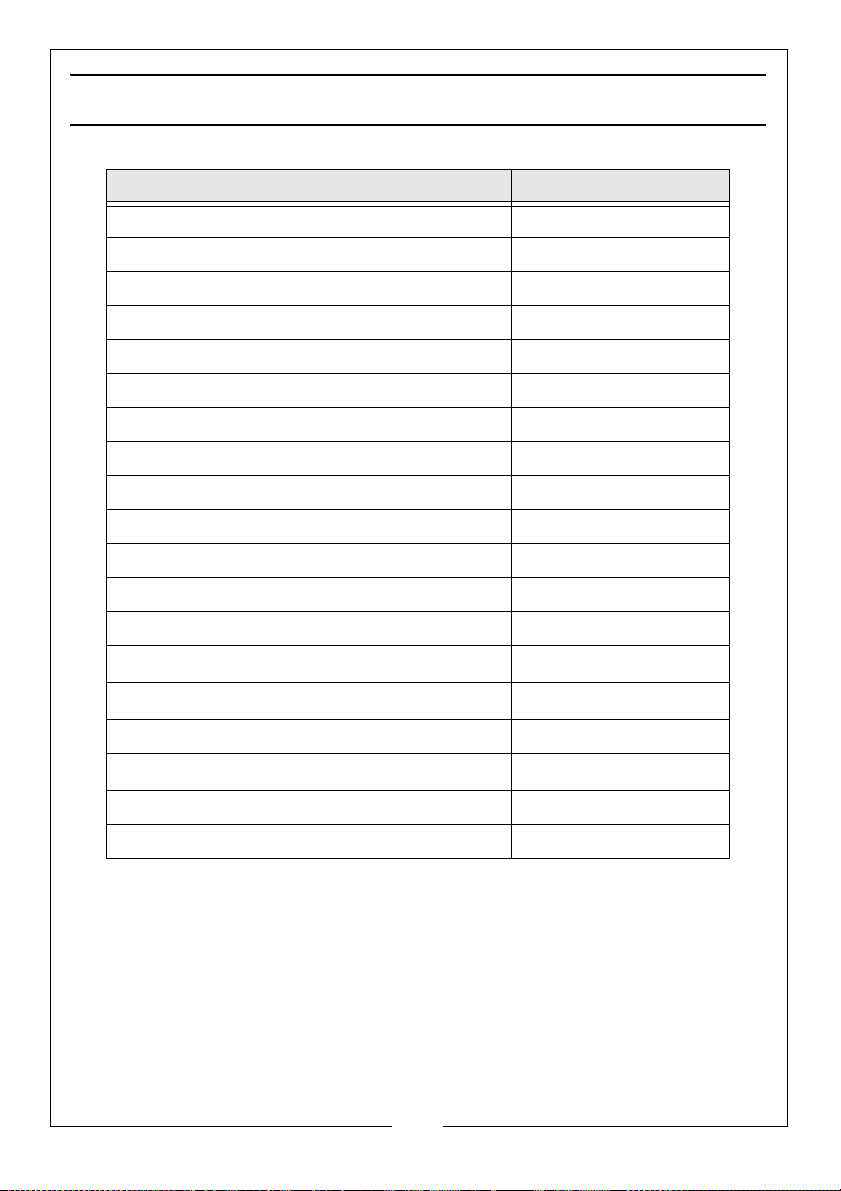
SPECIFICATIONS
Model Number CMS10S2
Part Number 6461514
Rated Voltage 230 V @ 50Hz
Input Wattage 1800 W
Blade Diameter 254 mm
Blade bore 30 mm
Max. blade thickness 2.8 mm
Max. blade speed 6000 RPM.
Max. crosscut capacity at 90° 340 mm x 78 mm
Max. mitre cut capacity at 45° 240 mm v 78 mm
Max. bevel cross-cut 45° 340 mm x 42 mm
Max. Compound Mitre Cut 240 mm x 42 mm
Max Bevel Angle 45° to the left
Sound pressure (L
Sound power (L
Uncertainty Factor (K) 3
Hand/arm weighted vibration
Dimensions (W x D (max) x H) 987 x 725 x 531 mm
) 91.9 dB (A)
pA
) 104.9 dB (A)
WA
< 2.5m/s
2
Weight 17 kg
To obtain the stated cutting capacities, always use 254 mm saw blades with a
30 mm bore, available from your local Clarke dealer.
24
Parts & Service: 020 8988 7400 / E-mail: [email protected] or [email protected]
Page 25

Page 26
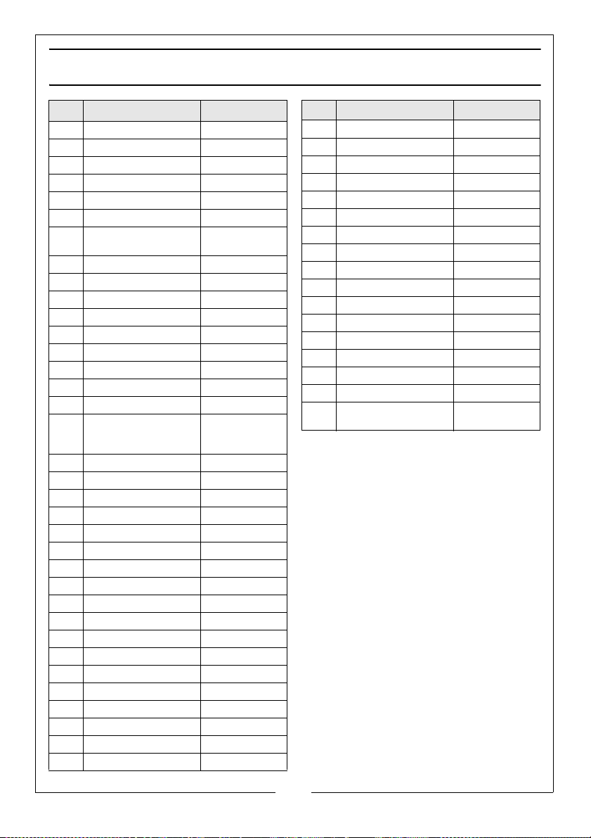
PARTS LIST
No Description Part No
2 Main Frame WSCMS10S202
3 Rubber Foot WSCMS10S203
7 Workpiece Support WSCMS10S207
10 Handle WSCMS10S210
14 Pointer WSCMS10S214
15 Table WSCMS10S215
21 Table Insert + Kerf
Plate
22 Shim WSCMS10S222
25 Stop Fence WSCMS10S225
28-34 Workpiece Clamp. WSCMS10S228
37 Screw WSCMS10S237
38 Bush WSCMS10S238
42 Joint WSCMS10S242
43 Collar Screw WSCMS10S243
49 Spring WSCMS10S249
50-53 Laser WSCMS10S250
53,
Laser battery box WSCMS10S253
56,
58
63 Bearing Housing WSCMS10S263
64 Spring WSCMS10S264
65 Slide Rail Locking Knob WSCMS10S265
67 Pin WSCMS10S267
70 Bevel Locking Lever WSCMS10S270
71 Linear Bearing WSCMS10S271
72 Guide Tube WSCMS10S272
75 Centre Screw WSCMS10S275
76 Outer Flange WSCMS10S276
77 Saw Blade WSCMS10S277
78 Shim WSCMS10S278
79 Inner Flange WSCMS10S279
80-81 Spindle With Pin WSCMS10S280
85 Bearing WSCMS10S285
87 Shell Layer WSCMS10S287
90 Dust Bag WSCMS10S290
96 Guard Support Arm WSCMS10S296
99 Blade Guard WSCMS10S299
WSCMS10S221
No Description Part No
101 Spring WSCMS10S2101
103 Washer WSCMS10S2103
107 Cover WSCMS10S2107
109 Guard Locking Lever WSCMS10S2109
111 Spring WSCMS10S2111
116 Bearing WSCMS10S2116
122 Anchor WSCMS10S2122
125 Stator WSCMS10S2125
128 Carbon Brush Holder WSCMS10S2128
129 Carbon Brushes (2) WSCMS10S2129
130 Carbon Brush Cover WSCMS10S2130
134 Carry Handle WSCMS10S2134
136 Upper Handle Cover WSCMS10S2136
138 Trigger Switch WSCMS10S2138
139 Lower Handle Cover WSCMS10S239
140 Filter WSCMS10S2140
120-
Motor WSCMS10S2120
123,
26
Parts & Service: 020 8988 7400 / E-mail: [email protected] or [email protected]
Page 27

DECLARATION OF CONFORMITY
27
Parts & Service: 020 8988 7400 / E-mail: [email protected] or [email protected]
Page 28

 Loading...