

Page 1
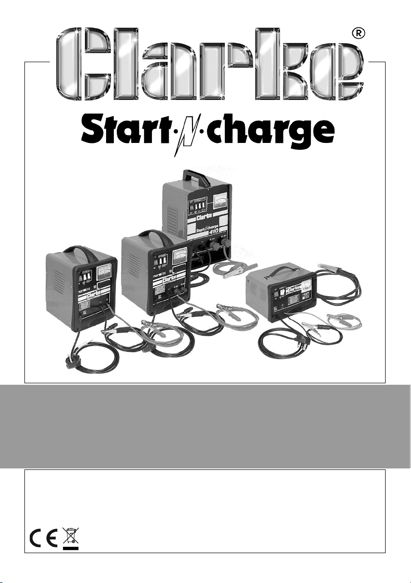
STARTER/CHARGERS
MODEL NO: 120C, 130C, 210C & 410E
PART NO: 6261090, 6261095, 6261130 & 6240100
OPERATION & MAINTENANCE
INSTRUCTIONS
ORIGINAL INSTRUCTIONS GC02/21 - rev 6
Page 2

INTRODUCTION
Thank you for purchasing this CLARKE Starter/Charger.
Please read this manual thoroughly, before attempting to operate, and
carefully follow all instructions given.
It is vitally important that all precautions are taken, as specified, which will not
only provide protection for yourself and that of others around you, but will also
ensure that the product will give you long and satisfactory service.
GUARANTEE
This CLARKE product is guaranteed against faulty manufacture for a period of
12 months from the date of purchase. Please keep your receipt as proof of
purchase.
This guarantee is invalid if the product is found to have been abused or
tampered with in any way, or not used for the purpose for which it was
intended.
Faulty goods should be returned to their place of purchase, no product can
be returned to us without prior permission.
This guarantee does not effect your statutory rights.
ENVIRONMENTAL RECYCLING POLICY
Through purchase of this product, the customer is taking on the
obligation to deal with the WEEE in accordance with the WEEE
regulations in relation to the treatment, recycling & recovery and
environmentally sound disposal of the WEEE.
In effect, this means that this product must not be disposed of with general
household waste. It must be disposed of according to the laws governing
Waste Electrical and Electronic Equipment (WEEE) at a recognised disposal
facility.
If disposing of this product or any damaged components, do not dispose of
with general waste. This product contains valuable raw materials. Metal
products should be taken to your local civic amenity site for recycling of metal
products.
2
Parts & Service: 020 8988 7400 / E-mail: [email protected] or [email protected]
Page 3
SAFETY PRECAUTIONS
WARNING: HIGHLY INFLAMMABLE HYDROGEN GAS IS RELEASED IN THE
PROCESS OF BATTERY CHARGING. ALWAYS REMEMBER TO SWITCH OFF
THE CHARGER/STARTER FIRST TO AVOID SPARKING.
PLEASE READ BEFORE USING THIS UNIT
1. Battery acid is very corrosive. If spilled, clean the area immediately and
wash with water. If battery acid comes into contact with the eyes, get
medical help immediately.
2. Do not expose this charger/starter to rain.
3. Never touch the negative and positive leads on this unit together while the
unit is switched on.
4. Never attempt any electrical or mechanical repair, other than
replacement of fuses. If you have a problem with your machine contact
your local stockist for service information.
WARNING: CERTAIN TYPES OF SEALED OR MAINTENANCE-FREE BATTERIES
NEED EXTRA CARE WHEN CHARGING. PLEASE CONSULT THE BATTERY
MANUFACTURERS INSTRUCTIONS BEFORE USING THIS CHARGER/STARTER
WARNING: TOXIC FUMES MAY BE RELEASED DURING BATTERY
CHARGING. ONLY USE THIS CHARGER/STARTER IN A WELL VENTILATED
AREA.
5. Before charging, make sure that the battery terminals are clean, and that
the cells are filled to the correct level by adding distilled water where
necessary.
6. This appliance is not intended for use by persons with reduced physical,
sensory or mental capabilities, or lack of experience and knowledge,
unless they have been given supervision or instruction concerning use of
the charger/starter by a person responsible for their safety. Keep children
well away from the charger/starter.
7. After charging, secure the vehicle battery leads to the correct terminals
which should be clean, and lightly smeared with petroleum jelly to prevent
corrosion. Finally, re-check the battery electrolyte level.
8. Do not use this charger/starter unless you are aware of vehicle electrical
systems, and battery charging techniques.
3
Parts & Service: 020 8988 7400 / E-mail: [email protected] or [email protected]
Page 4
9. Always consult the vehicle manufacturers instructions for disconnecting /
charging the vehicle battery.
CAUTION: SOME ELECTRONIC EQUIPMENT CAN BE DAMAGED BY BOOST
CHARGING OR USE OF START FACILITY. CHECK YOUR VEHICLE
HANDBOOK BEFORE USING YOUR STARTER/CHARGER. IF IN DOUBT
CONSULT THE VEHICLE MANUFACTURER.
ELECTRICAL CONNECTIONS
BC120C, BC130C AND BC210C
These chargers are provided with a standard (BS1363) 13 amp plug, for use
with a standard 230V 50Hz domestic supply.
The fuse in the plug for these appliances must be rated at 13 amps.
BC410E
Connect the three core mains cable to a suitable industrial supply isolator, or
heavy duty plug meeting the requirements of BS EN 60309. This charger must
be connected to a supply having a rated capacity of greater than 13 Amps.
Connect the three core mains lead to a suitable industrial supply isolator or
heavy duty plug. This charger must be connected to a supply having a rated
capacity of greater than 13 Amps. A normal 13 Amp (BS1363) plug must NOT
be used.
NOTE: The maximum input current for this unit is 25 amps.
WARNING: THIS APPLIANCE MUST BE EARTHED.
IMPORTANT: The wires in this mains lead are coloured in accordance with
the following code:
GREEN AND YELLOW - EARTH E )
BLUE - NEUTRAL (N)
BROWN - LIVE (L)
As the colours of the flexible cord of this appliance may not correspond with
the coloured markings identifying terminals in your plug, proceed as follows:
• Connect GREEN AND YELLOW coloured cable to plug terminal marked
letter “E” or Earth Symbol or coloured or Green and Yellow.
• Connect BROWN cable to the plug terminal marked letter ‘L’ or
coloured Red.
• Connect BLUE cable to the plug terminal marked letter “N’ or coloured
Black.
4
Parts & Service: 020 8988 7400 / E-mail: [email protected] or [email protected]
Page 5
OVERVIEW
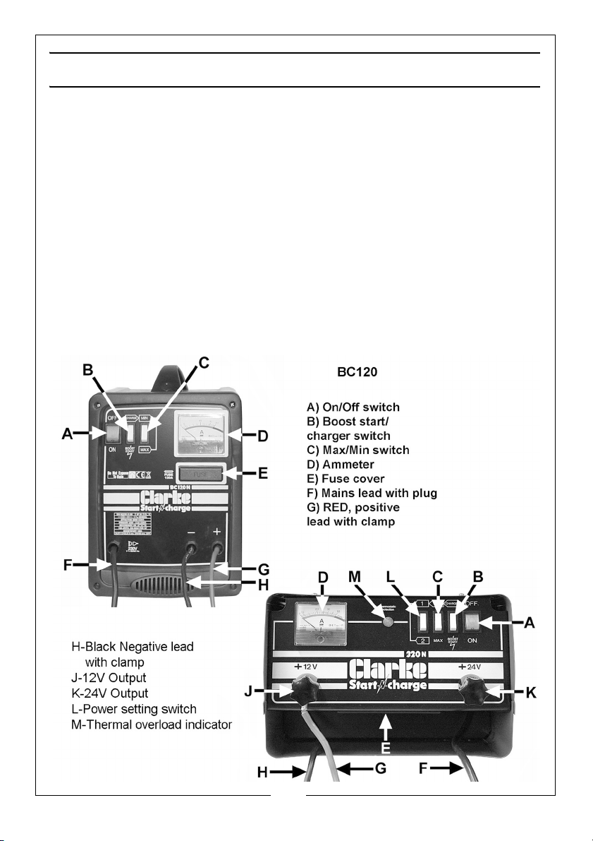
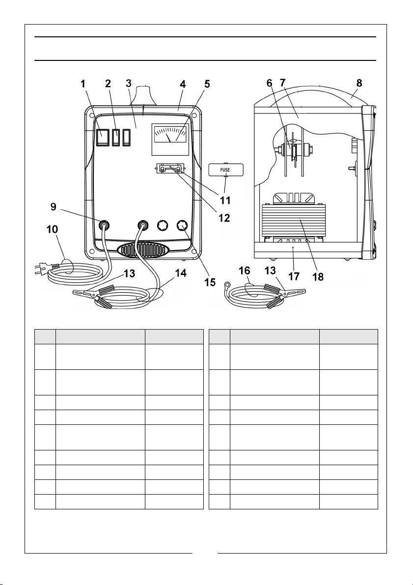
All models are similar and are provided with a pair of leads complete with
clamps for connection to a battery. Those models capable of 24V charging
are provided with appropriate outlet connections - 12V and 24V as shown
below.
A single, Boost Start/ Charge switch allows for switching between functions.
A MAX/MIN switch allows for charging at two different rates. Larger models
are also provided with a two position Power Setting switch, which allows for
even greater control of charge rates, as displayed on the Ammeter.
The main fuse is mounted on the front panel, as shown, except for model
BC130C which has the fuse mounted on the back panel.
Larger models have a Thermal Overload indicator fitted, see below. Please
read Thermal Overload notes on page 8.
The illustration below identifies the various components and controls which are
similar for all products.
5
Parts & Service: 020 8988 7400 / E-mail: [email protected] or [email protected]
Page 6

PROCEDURE FOR NORMAL CHARGING
NOTE: Before charging or boosting, ensure that, where applicable, the cells
are filled with electrolyte to the correct level by adding distilled water.
1. When charging a car battery in situ, we recommend that the non earthed
lead on the battery is disconnected prior to charging (On most vehicles,
this would be the RED, Positive lead - but check the vehicle handbook if
you are unsure).
This precaution is necessary as it is possible that damage could occur to any
electronically controlled system fitted to the vehicle, such as engine
management system, anti-theft alarm, alternator etc.
2. Check that the ON/OFF switch on the unit is in the OFF position.
3. Connect the RED, positive lead to either the 12V or 24V output on the
charger, as appropriate.
4. Connect the appropriate clamp to the unearthed battery terminal. On
most modern cars this is the RED, positive clamp connected to the RED,
positive terminal of the battery, but check your handbook if unsure. Then
connect the other clamp to the chassis (or a suitable engine bolt) away
from the battery and fuel line.
5. Remove the battery filler caps, where applicable, during charging, in order
to prevent the build up of dangerous gases within the battery.
6. Switch the CHARGE/BOOST START switch to the CHARGE position.
NOTE: For those chargers provided with a Power setting switch (models
(BC410E ), set the switch to position ‘1’.
7. Set the MIN (minimum charge) MAX (maximum charge) switch to the MIN
position. This is suitable for charging most normal car batteries (having an
ampere hour rating of approximately 40 A.H.).
8. Switch the ON/OFF switch to ON, and charging will commence.
Adjustments may be made to the charging rate by switching to MAX, and
on larger models by also switching the Power Setting switch to the 1 or 2
position as appropriate. i.e. 4 charging rates are possible - MIN-1, MIN-2,
MAX-1 and MAX-2.
6
Parts & Service: 020 8988 7400 / E-mail: [email protected] or [email protected]
Page 7

9. Keep the battery on charge until the ammeter gauge reads zero (or 0-2
amps) or has stopped moving down. Then switch off at the machine.
WARNING: IF THE FIXED POSITIVE LEAD AND THE FIXED NEGATIVE LEAD
ARE CONNECTED TO THE WRONG TERMINALS, A FLASH WILL OCCUR
WHEN THE 2ND. CLAMP IS ATTACHED. DAMAGE TO THE CHARGING UNIT
AND THE BATTERY WILL BE AVOIDED AS YOUR STARTER/CHARGER IS FITTED
WITH A POLARITY PROTECTION FEATURE. IT WILL HOWEVER BE NECESSARY
TO REPLACE THE INTERNAL FUSE. REMOVE THE BLACK PLASTIC COVER ON
THE FRONT PANEL (MARKED FUSE) AND REPLACE THE DAMAGED FUSE.
NOTES ON CHARGING PROCEDURE
• A complete charge is best done slowly in order to protect your battery
so we recommend the MIN setting as described above.
• A complete charge may take up to 10 hours.
• If a low amperage reading (2 amps or less) is seen on the gauge at
either the MIN or MAX setting. This may indicate that the battery is either
(a) already fully charged or (b) at the end of its useful life and in need of
replacement.
• Do not charge the battery for longer than is necessary.
WARNING: NEVER ATTEMPT TO RE-CHARGE NON-RECHARGEABLE BATTERIES
7
Parts & Service: 020 8988 7400 / E-mail: [email protected] or [email protected]
Page 8

PROCEDURE FOR ENGINE STARTING
NOTE: We recommend that before attempting to boost start, you charge the
battery for 10-15 minutes. This will improve the chance of a first time
start, particularly with bigger engines. When the battery is completely
flat, you must charge the battery for 10-15 minutes before attempting
to start, otherwise you may cause damage to the vehicle electronic
systems.
1. Check that the ON/OFF switch is in the OFF position.
2. Connect the cables as for normal charging.
3. Check that the CHARGE/BOOST START switch is in the CHARGE position.
4. Switch the ON/OFF switch to the ON position.
5. Turn the key in the vehicle’s ignition to ‘START’, and get an assistant to
switch the CHARGE/BOOST START switch to BOOST START position.
IMPORTANT: If the engine fails to start almost immediately, you MUST
the CHARGE/BOOST START switch to CHARGE position after a maximum
period according to the BOOST START DUTY CYCLE - i.e. 10 secs ON followed
by 30 secs before retrying.
IMPORTANT: Failure to do this could damage some vehicle electronic
equipment, the battery, and possibly the Charger unit which may
invalidate your guarantee.
return
THERMAL OVERLOAD
This starter/charger is provided with a Thermal Overload cut-out.
Should the Duty Cycle be exceeded or should the unit overheat for any
reason, the thermal overload will intervene, shutting down the charger.
If this occurs, wait for 15 - 20 minutes, depending upon ambient temperature,
before attempting to re-use.
The amber indicator lamp on the panel will illuminate when the overload has
intervened. It will extinguish once it has reset and the unit is ready for use once
again.
8
Parts & Service: 020 8988 7400 / E-mail: [email protected] or [email protected]
Page 9
MAINTANENCE
This charger requires minimal maintenance. As with any appliance, a few
common sense rules will prolong its working life.
WARNING: ALWAYS BE SURE THE CHARGER IS DISCONNECTED FROM THE
MAINS AND ANY BATTERY BEFORE PERFORMING ANY MAINTENANCE OR
CLEANING.
1. Clean the case and leads with a moist cloth.
2. Clean corrosion from the clamps with a solution of water and baking soda.
3. Examine the leads at regular intervals for damage and have them
replaced if necessary.
WARNING: ALL OTHER SERVICING/REPAIRS SHOULD BE DONE BY
QUALIFIED SERVICE PERSONNEL ONLY.
STORAGE
1. Wind up the connecting leads and power cable when not in use and store
in the compartment when not being used.
2. Store in a clean, dry place.
REPLACEMENT FUSES
ODEL PART NO AMPS QTY REQUIRED
M
BC120C EM22220044 80 1
BC130C EM22220044 80 1
BC210C EM22220047 100 1
BC410E EM22220031 75 2
9
Parts & Service: 020 8988 7400 / E-mail: [email protected] or [email protected]
Page 10

DECLARATION OF CONFORMITY
10
Parts & Service: 020 8988 7400 / E-mail: [email protected] or [email protected]
Page 11
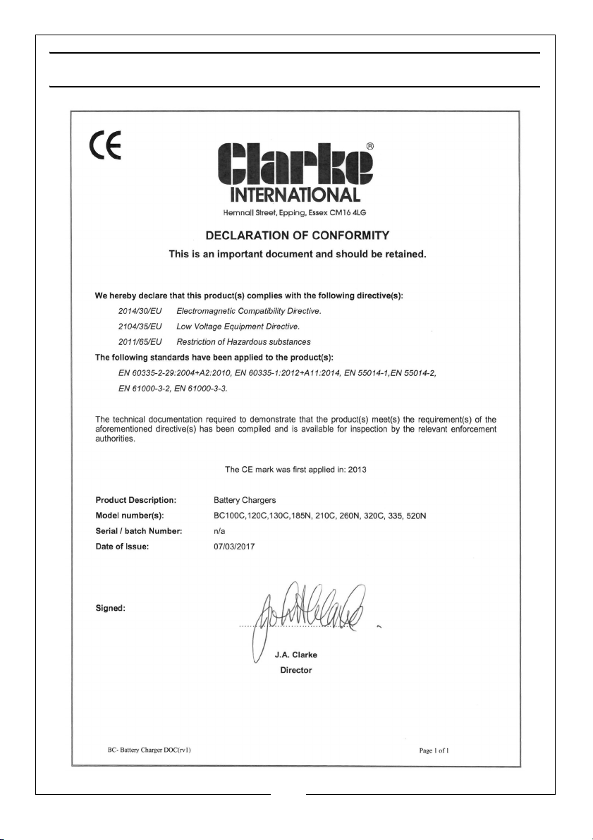
DECLARATION OF CONFORMITY
11
Parts & Service: 020 8988 7400 / E-mail: [email protected] or [email protected]
Page 12
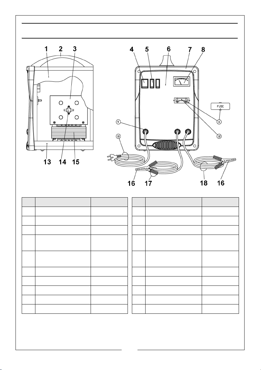
PARTS LIST - BC120C
No Description Part No No Description Part No
1 Cover panel EM33705460 11 Fuse Holder Box Kit EM04600251
2 Handle EM21600045 12 Fuse 80A EM22220044
3 Rectifier 4 Diodes EM22400042 13 Lower panel EM33700078
4 Green Pilot Light /
Switch 16A-250V
5 Current Switch 16A
250V
6 Front Panel EM33710634 16 Clamps 60A EM04600066
7 Frame For Starter EM21690441 17 Black cable/clamp EM43200082
8 Ammeter 20A EM22600062 18 Red Cable/clamp EM43200030
9 Cable Clamp EM21605009
10 Input Cable & Plug EM20220067
EM22200039 14 Thermostat 1001
I0A
EM22200038 15 Transformer 230v EM44105033
EM22210014
12
Parts & Service: 020 8988 7400 / E-mail: [email protected] or [email protected]
Page 13
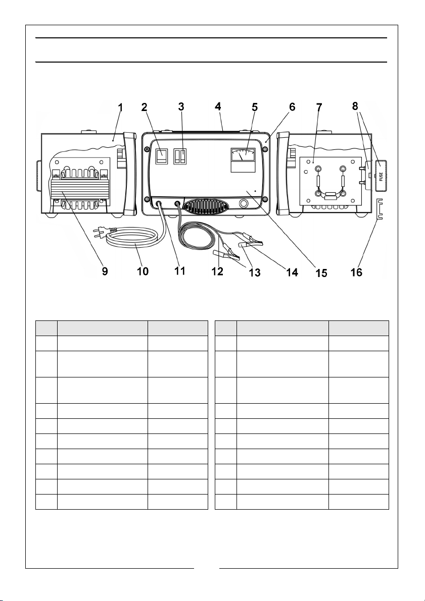
PARTS LIST - BC130C
No Description Part No No Description Part No
1 Cover EM33705451 11 Cable Clamp EM21605009
2 Green Pilot Light
Switch 16A-250V
3 Current Switch 16A
250V White
4 Kit Handle + Clips EM04600259 14 Red Cable 1,6m EM43200056
5 Ammeter 20A EM22600062 15 Lower Panel EM33700380
6 Frame EM21690440 16 Fuse 80A EM22220044
7 Rectifier 4 Diodes EM22400042
8 Fuse Holder EM04600251
9 Transformer 230V EM44105060
10 Input Cable / Plug EM20220067
EM22200039 12 Black Cable 4 sq/
mm 1,6m R60A
EM22200038 13 Clamps 60A EM04600066
EM43200055
13
Parts & Service: 020 8988 7400 / E-mail: [email protected] or [email protected]
Page 14
PARTS LIST - BC210C
No Description Part No No Description Part No
1 Green Pilot Light
Switch
2 Welding Current
Switch
3 Front Panel EM33710629 12 Fuse 100A EM22220047
4 Frame for Starter EM21690441 13 Clamps 60A EM04600066
5 Ammeter 20A/Start EM22600062 14 Black (Neg) cable/
6 Rectifier 35A EM22400100 15 Red handwheel EM04600005
7 Cover Panel EM33705460 16 Red Cable 60A EM43200057
8 Handle EM21600045 17 Lower Panel EM33700078
9 Cable Clamp EM21605009 18 Transformer EM44105078
EM22200039 10 Input Cable & plug EM20220067
EM22200038 11 Fuse Holder Box Kit EM04600251
EM43200082
clamp
14
Parts & Service: 020 8988 7400 / E-mail: [email protected] or [email protected]
Page 15
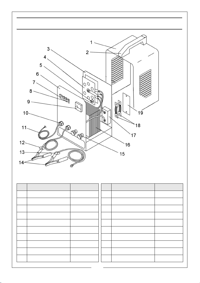
PARTS LIST - BC410E
No Description Part No No Description Part No
1 Upper Panel EM33705007 11 Input Cable EM20220014
2 Handle EM21600004 12 Black Cable EM43200012
3 Back Panel EM33715037 13 Red Cable EM43200050
4 Rectifier EM22400020 14 Clamps 120A EM04600067
5 Thermostat EM04600113 15 Black Connector EM04600022
6 Lower Panel EM33700088 16 Transformer EM44105038
7 Green Switch EM22200039 17 Fuse Holder Box EM21690113
8 Current Switch EM22200038 18 Fuse 75A EM22220031
9 Ammeter 30A EM22600009 19 Small Fuse Cover EM21690109
10 Cable Clamp EM04600233
15
Parts & Service: 020 8988 7400 / E-mail: [email protected] or [email protected]
Page 16
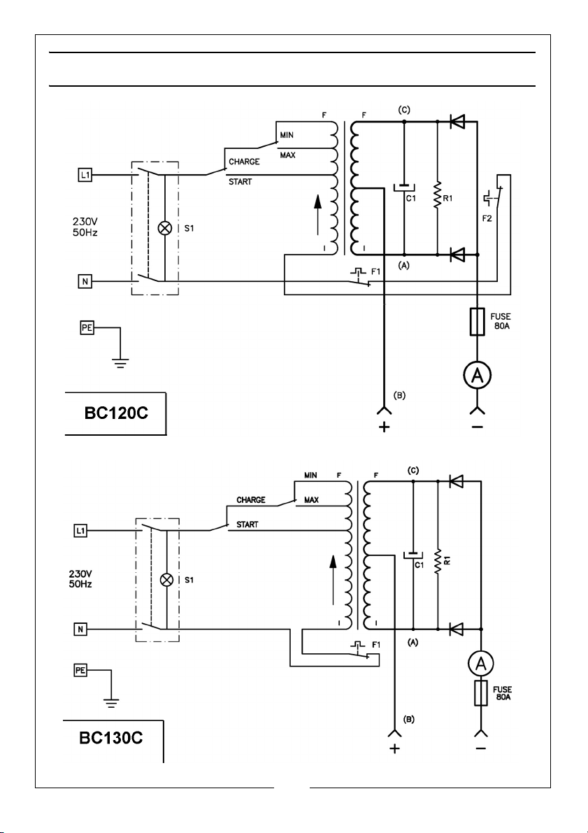
WIRING CIRCUIT DIAGRAMS
16
Parts & Service: 020 8988 7400 / E-mail: [email protected] or [email protected]
Page 17
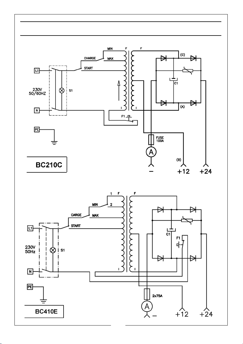
WIRING CIRCUIT DIAGRAMS
17
Parts & Service: 020 8988 7400 / E-mail: [email protected] or [email protected]
Page 18
SPECIFICATIONS
Model Number BC120C BC130C BC210C BC410E
Part No 6261090 6261095 6261130 6240100
Dimensions (DxWxH) 215 x 215 x
300
Weight 9 kg 7 kg 12 kg 18 kg
Input Voltage @50Hz 230 V AC 230 V AC 230 V AC 230 V AC
Duty Cycle (Starting) 5 sec On / 20
sec Off
Max charge 15A 15A 25A 35
Max Boost 120A 120A 200A 400A
Boost/Charge 12V 12V 12/24V 12/24V
280 x 275 x
280
5 sec On / 30
sec Off
215 x 215 x
300
10 sec On /
60 sec Off
250 x 270 x
440
10 sec On /
30 sec Off
18
Parts & Service: 020 8988 7400 / E-mail: [email protected] or [email protected]
Page 19

NOTES
___________________________________________________________________________
___________________________________________________________________________
___________________________________________________________________________
___________________________________________________________________________
___________________________________________________________________________
___________________________________________________________________________
___________________________________________________________________________
___________________________________________________________________________
___________________________________________________________________________
___________________________________________________________________________
___________________________________________________________________________
___________________________________________________________________________
___________________________________________________________________________
___________________________________________________________________________
19
Parts & Service: 020 8988 7400 / E-mail: [email protected] or [email protected]
Page 20

 Loading...