

Page 1
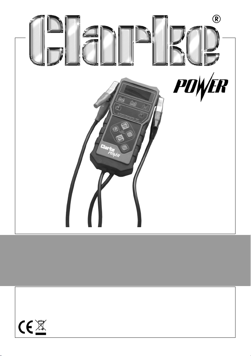
DIGITAL BATTERY TESTER
MODEL NO: CDBT1
PART NO: 6260115
OPERATING INSTRUCTIONS
GC0614
Page 2
INTRODUCTION
Thank you for purchasing this CLARKE product.
Before attempting to use this product, please read this manual thoroughly and
follow the instructions carefully. In doing so you will ensure the safety of yourself
and that of others around you, and you can look forward to your purchase
giving you long and satisfactory service.
GUARANTEE
This product is guaranteed against faulty manufacture for a period of 12
months from the date of purchase. Please keep your receipt which will be
required as proof of purchase.
This guarantee is invalid if the product is found to have been abused or
tampered with in any way, or not used for the purpose for which it was
intended.
Faulty goods should be returned to their place of purchase, no product can
be returned to us without prior permission.
This guarantee does not effect your statutory rights.
ENVIRONMENTAL RECYCLING POLICY
Through purchase of this product, the customer is taking on the
obligation to deal with the WEEE in accordance with the WEEE
regulations in relation to the treatment, recycling & recovery and
environmentally sound disposal of the WEEE.
In effect, this means that this product must not be disposed of with general
household waste. It must be disposed of according to the laws governing
Waste Electrical and Electronic Equipment (WEEE) at a recognised disposal
facility.
2
Parts & Service: 020 8988 7400 / E-mail: [email protected] or [email protected]
Page 3
FEATURES
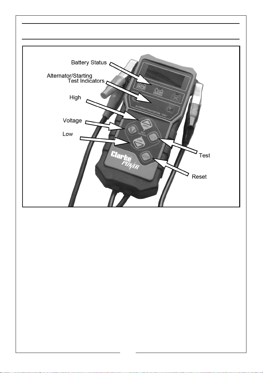
The CDBT1 incorporates green & red LEDs to show immediate information and
includes the following functional features:
• Shows CCA (Cold Cranking Amps) at the end of each test.
• Displays an expanded measurement range from 100-1400CCA.
• Tests discharged batteries.
• Identifies defective battery cells.
• Incorporates ‘Voltmeter mode’ for testing both the starter and charging
systems.
• Incorporates High/Low voltage capture for improved starter/charging
system testing.
Parts & Service: 020 8988 7400 / E-mail: [email protected] or [email protected]
3
Page 4

SAFETY PRECAUTIONS
1. Always avoid creating sparks in a battery charging environment, as this
could cause a fire, or even an explosion.
Similarly, it is vital to avoid creating sparks when testing a battery in a motor
vehicle in situ, as spikes in the system could cause serious damage to the
vehicle electronic circuitry.
Ensure that the RED or POSITIVE clamp does not touch any other part of the
vehicle, and be particularly careful where you place the tester within the
engine compartment.
2. Avoid dropping the tester, as this could cause damage, which may not
prevent the device from working, but could nevertheless cause the
readings to be inaccurate.
BEFORE USE
1. Check the battery for cracks or leakage. If damage is found, do not test,
replace the battery.
2. If possible, check electrolyte levels and top up with distilled water if
necessary.
3. Clean the battery terminals with a wire brush if not already clean & bright.
4. Turn off the vehicle including all accessory loads.
• Testing with the ignition switch on or electrical loads present such as
boot light, interior light etc will cause inaccurate readings.
4
Parts & Service: 020 8988 7400 / E-mail: [email protected] or [email protected]
Page 5
BATTERY TEST
NOTE: If testing in-situ, ensure all lights and accessories are switched off
and the key is removed.
NOTE: Make a note of the battery rating system (e.g SAE) and rating (e.g
300) as shown on the battery.
1. Connect the RED clamp to the POSITIVE (+) terminal and the BLACK clamp
to the NEGATIVE (-) terminal.
• The rating system that was last selected will be shown briefly on the
display (e.g SAE) for 1 second followed by the default rating.
• If the rating system is incorrect see CHANGING THE RATING SYSTEM on
page 6.
2. Use the HIGH/LOW arrow buttons to scroll to the battery rating e.g 300Ah.
3. Press the TEST button to start the test.
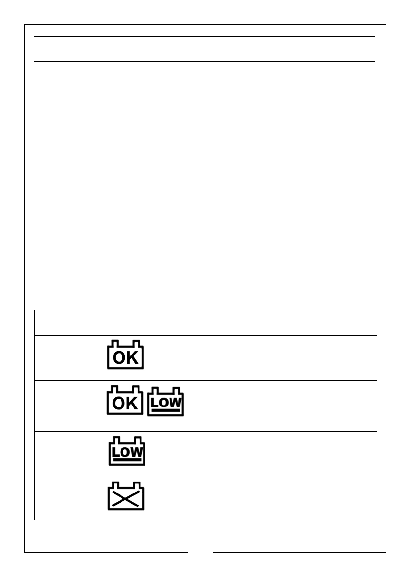
• One or more ‘Battery Status’ LEDs will light up, (see results chart below).
• The display will alternate between the voltage and CCA by pressing the
TEST button.
BATTERY TEST RESULTS
Battery
Status LEDs
Green The battery is good. Return to use.
Green and
Yellow
Yellow Fully charge the battery and retest. If
Red The battery has failed or is weak and
Parts & Service: 020 8988 7400 / E-mail: [email protected] or [email protected]
Decision
Fully charge the battery and return it
to use
you get the same result after charging,
replace the battery.
may soon fail. Replace the battery.
5
Page 6
CHANGING THE RATING SYSTEM
1. Disconnect the clamps and connect the positive clamp (red) to the
positive terminal.
2. Press the hold the TEST button.
3. Connect the negative clamp (black) to the negative (-) terminal.
4. After the display shows the letters of the rating system with dots (for
example, C.C.A), release the TEST button.
5. Use the HIGH arrow / LOW arrow buttons to scroll to the correct rating
system.
6. Press the TEST button to select the rating system. The default rating will
appear.
7. Continue with step 2 in “BATTERY TEST”.
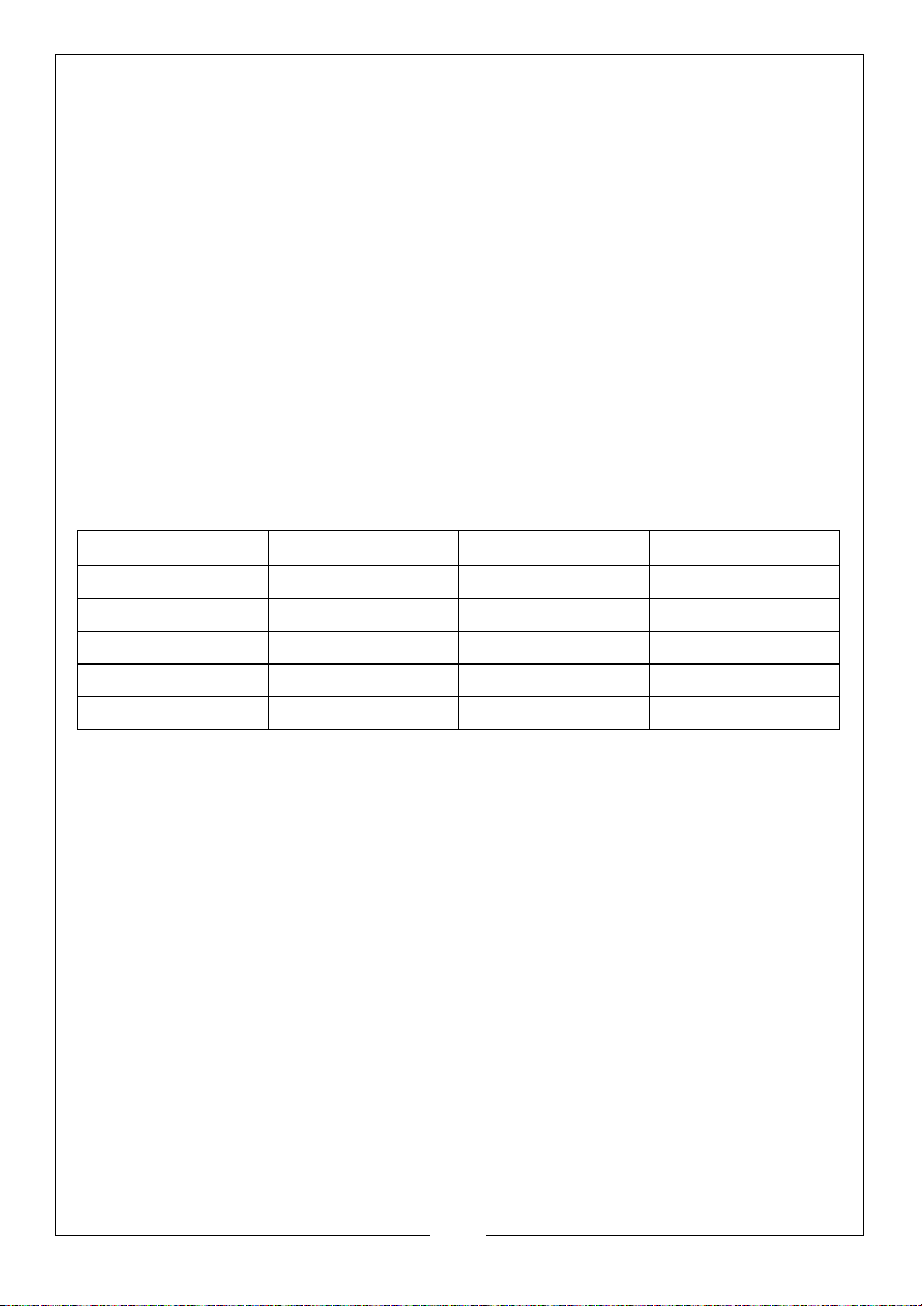
RATING SYSTEM CHART
Rating System* Increment Default rating Range
CCA 20 500 100-1400
SAE 20 600 100-1400
EN 20 600 100-1400
IEC 10 280 100-800
DIN 10 280 100-800
STARTING SYSTEM TEST
NOTE: The battery must be good and fully charged for this test.
1. Connect the tester clamps to the battery: RED clamp to the POSITIVE (+)
terminal and the BLACK clamp to the NEGATIVE (-) terminal. Check each
clamp is making a good connection.
2. Press the VOLTAGE button to read the live voltage.
3. Start the vehicle.
4. Press and hold the LOW arrow button to read the cranking voltage.
6
Parts & Service: 020 8988 7400 / E-mail: [email protected] or [email protected]
Page 7
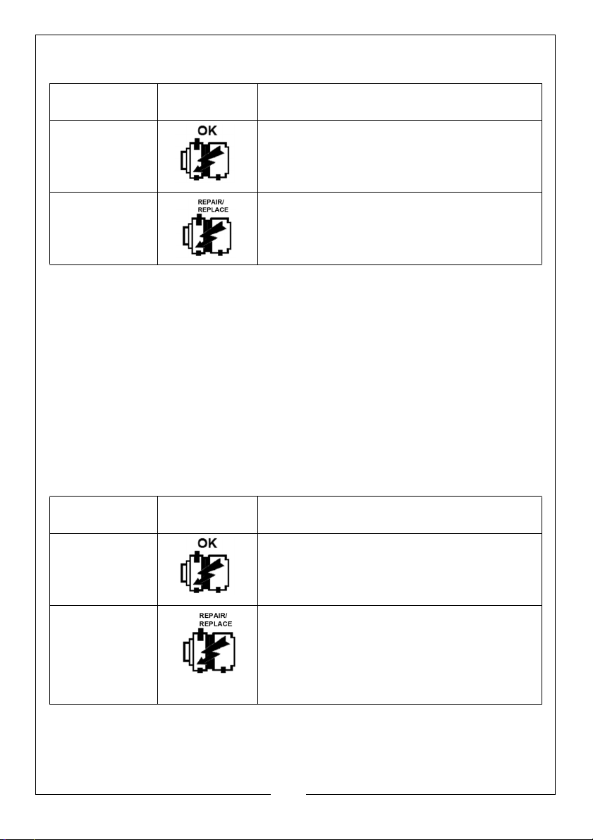
STARTING SYSTEM TEST RESULTS
Starting Test
Indicator LEDs
Green The cranking voltage is greater than 9.6V
Red The cranking voltage is less than 9.6V which
Decision
The starting system is OK.
indicates a starting system problem. Check
the connections, wiring and starter.
CHARGING SYSTEM TEST
NOTE: The battery must be fully charged for this test.
1. When the vehicle engine is running, connect the RED clamp to the
POSITIVE (+) terminal and the BLACK clamp to the NEGATIVE (-) terminal.
2. Press the VOLTAGE button to read the live voltage.
3. Rev the engine to 2000 rpm for 15 seconds.
4. Press and hold the HIGH arrow button to read the highest average
charging voltage.
CHARGING SYSTEM TEST RESULTS
Starting Test
Indicator LEDs
Green The highest average charging voltage is
Red The highest average charging voltage is
Parts & Service: 020 8988 7400 / E-mail: [email protected] or [email protected]
Decision
between 13.3V and 15.5V. The charging
system is OK.
less than 13.3V or greater than 15.5V which
indicates a charging system problem. If less
than 13.3V, check the connections, wiring
and alternator. If greater than 15.5V, check
the charging regulator.
7
Page 8
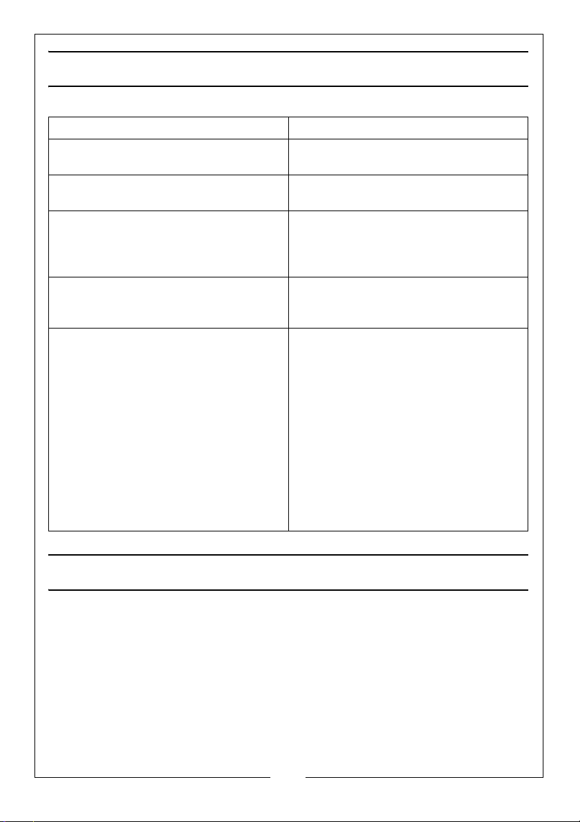
TROUBLESHOOTING
CONDITION OBSERVED RECOMMENDED ACTION
Display flashes or shows one flashing
letter
Message showing that alternates
between “BAD” and “CELL”
Message “CON” displayed. This shows a bad connection.
Top panel red LED lights up when
testing in-vehicle
Excessive electromagnetic
interference causing the tester to reset during testing.
Battery is too low (<8 Volts) to test.
Fully charge the battery and retest.
One or more battery cells are
defective. Replace the battery.
Disconnect the clamps and reconnect. Ensure that a good
connection is achieved.
Possible poor connection between
battery cables. Re-test at the battery
posts before replacing the battery.
Before re-testing, reconnect the
clamps and ensure the ignition is off
and all electrical loads are removed.
Move away from the noise source
(such as a charger or other highcurrent device.
If unable to find the noise source,
fully charge the battery and re-test
at the battery terminals. If the toppanel red LED lights up again,
replace the battery.
MAINTENANCE
As the metal clamps are liable to come into contact with battery electrolyte, it
is advisable to wipe them clean and dry after use, and apply a thin film of
silicon grease to prevent the possibility of corrosion.
8
Parts & Service: 020 8988 7400 / E-mail: [email protected] or [email protected]
Page 9
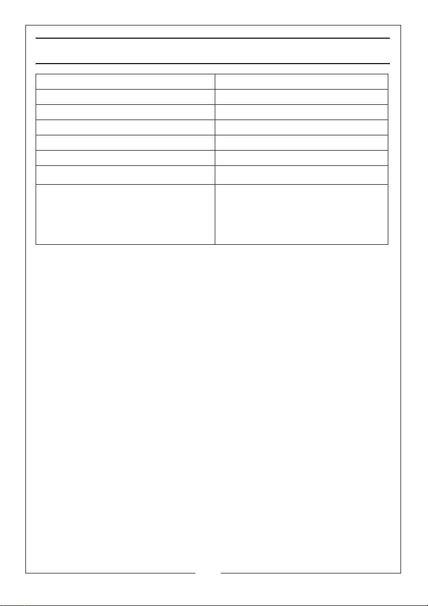
SPECIFICATION
Model Number CDBT1
Product Dimensions: (L x W x H) 210 x 115 x 50 mm
Weight 0.37 kg
Housing Material Acid/impact resistant ABS
Display Seven segment LED display
Voltage r a n g e 7.6 - 1 7 Vo l t D C
Operating Temperature
Rating System CCA = 100-1400
°
F (-18 - 50°C)
0-120
SAE = 100 - 1400
EN = 100 - 1400
IEC = 100 - 800
DIN = 100 - 800
9
Parts & Service: 020 8988 7400 / E-mail: [email protected] or [email protected]
Page 10
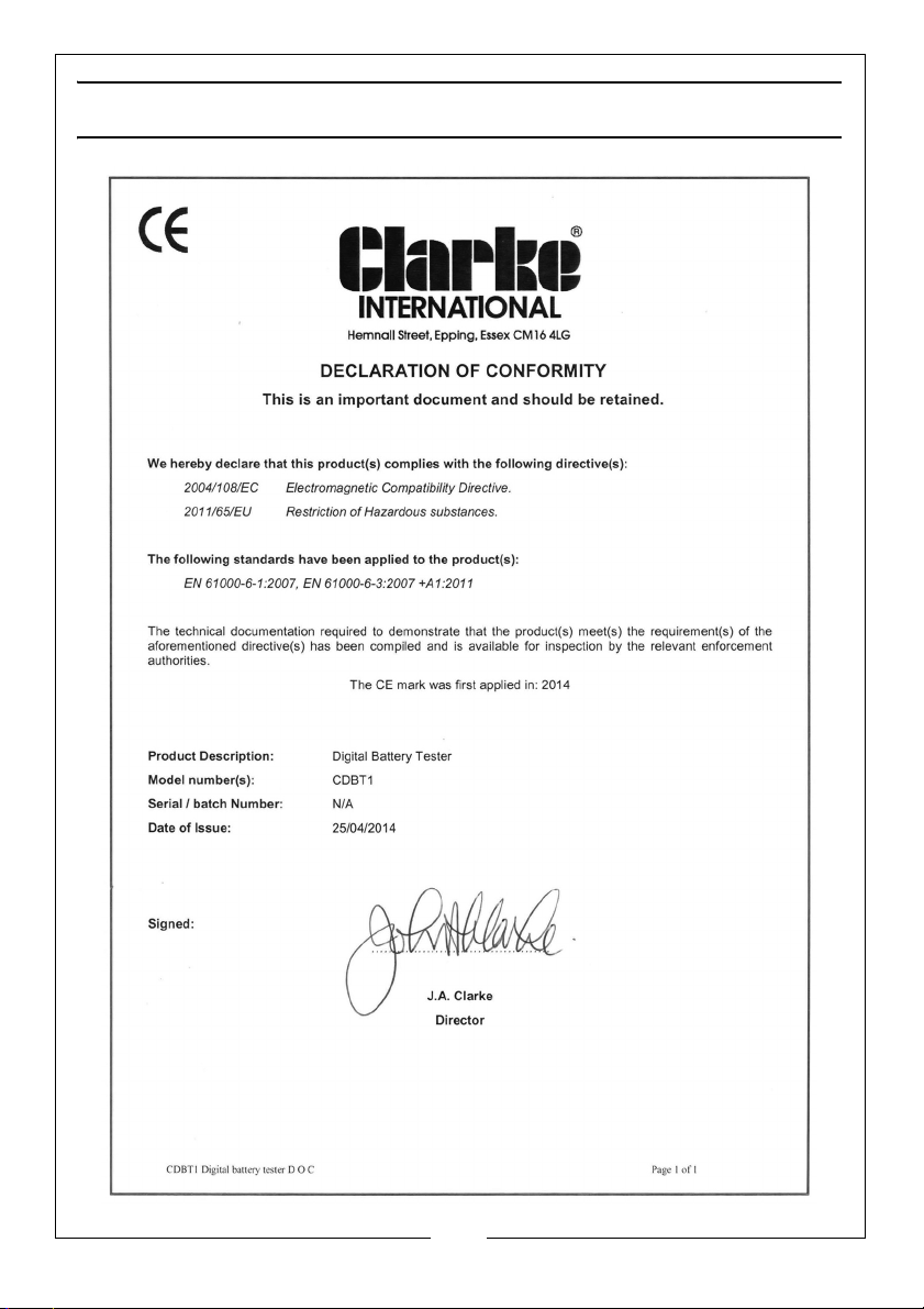
DECLARATION OF CONFORMITY
10
Parts & Service: 020 8988 7400 / E-mail: [email protected] or [email protected]
Page 11

NOTES
____________________________________________________________________________
____________________________________________________________________________
____________________________________________________________________________
____________________________________________________________________________
____________________________________________________________________________
____________________________________________________________________________
____________________________________________________________________________
____________________________________________________________________________
____________________________________________________________________________
____________________________________________________________________________
____________________________________________________________________________
____________________________________________________________________________
____________________________________________________________________________
____________________________________________________________________________
11
Parts & Service: 020 8988 7400 / E-mail: [email protected] or [email protected]
Page 12

 Loading...