

Page 1
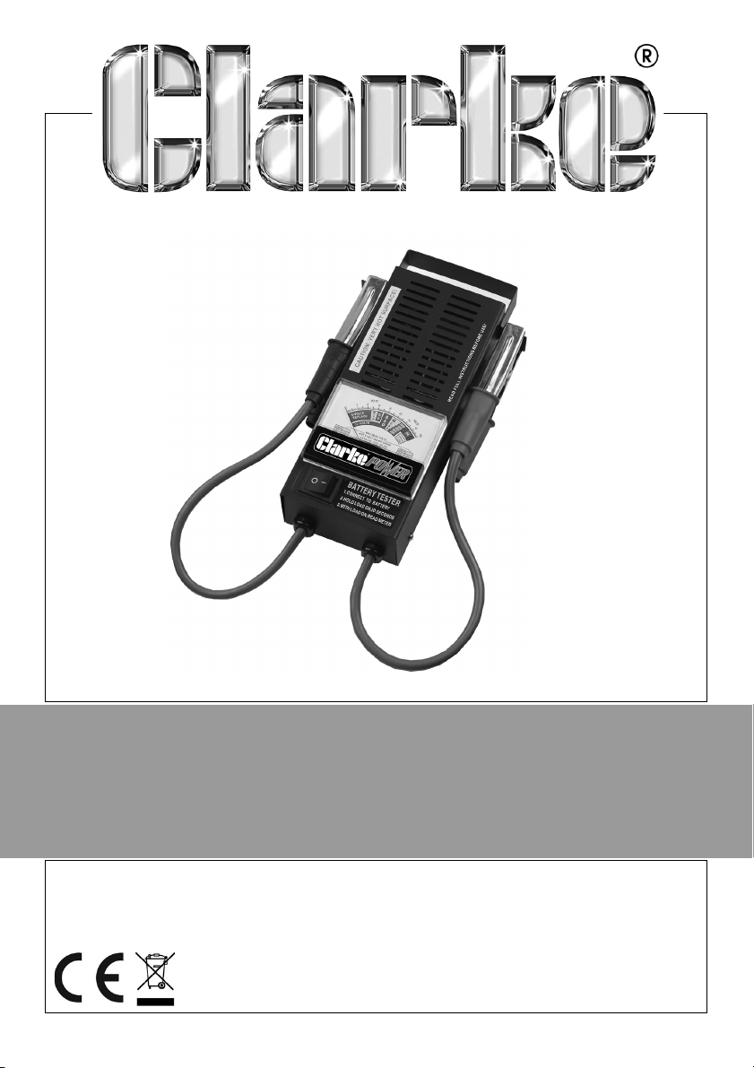
BATTERY TESTER
MODEL NO: CVT2
PART NO: 6260103
OPERATION & MAINTENANCE
INSTRUCTIONS
ORIGINAL INSTRUCTIONS
LS0720 - ISS 3
Page 2
INTRODUCTION
Thank you for purchasing this CLARKE product.
Before attempting to use this product, please read this manual thoroughly and
follow the instructions carefully. In doing so you will ensure the safety of yourself
and that of others around you, and you can look forward to your purchase
giving you long and satisfactory service.
GUARANTEE
This product is guaranteed against faulty manufacture for a period of 12
months from the date of purchase. Please keep your receipt which will be
required as proof of purchase.
This guarantee is invalid if the product is found to have been abused or
tampered with in any way, or not used for the purpose for which it was
intended.
Faulty goods should be returned to their place of purchase, no product can
be returned to us without prior permission.
This guarantee does not effect your statutory rights.
ENVIRONMENTAL RECYCLING POLICY
Through purchase of this product, the customer is taking on the
obligation to deal with the WEEE in accordance with the WEEE
regulations in relation to the treatment, recycling & recovery and
environmentally sound disposal of the WEEE.
In effect, this means that this product must not be disposed of with general
household waste. It must be disposed of according to the laws governing
Waste Electrical and Electronic Equipment (WEEE) at a recognised disposal
facility.
2
Parts & Service: 020 8988 7400 / E-mail: [email protected] or [email protected]
Page 3
SAFETY PRECAUTIONS
1. Always avoid creating sparks in a battery charging environment, as this
could cause fire, or even an explosion.
Similarly, it is vital to avoid creating sparks when testing a battery in a motor
vehicle in situ, as spikes in the system could cause serious damage to the
vehicle electronic circuitry.
Ensure that the RED or POSITIVE clamp does not touch any other part of the
vehicle, and be particularly careful where you place the tester within the
engine compartment. The main body of the tester is metal, and if placed
carelessly, it could cause a short circuit and hence damage to the
electrical system.
2. Avoid dropping the tester, as this could cause damage, which may not
prevent the device from working, but could nevertheless cause the
readings to be inaccurate.
OPERATION
With the meter disconnected from the battery, ensure the gauge needle is set
to zero, using the screw on the front of the gauge as necessary.
BATTERY TEST
Make sure that the battery contacts are clean and firm, and that on small
batteries, there is absolutely no possibility of the clamps touching each other.
1. Connect the RED clamp to the POSITIVE terminal.
2. Connect the BLACK clamp to the NEGATIVE terminal.
3. Press and hold the spring loaded LOAD Switch, for at least 5 seconds (Do
not exceed 10 seconds) to allow the load to take effect. With the load
switch held, read the condition of the battery on the scale provided,
referring to the Battery Analysis chart, on the following page.
CHARGING SYSTEM TEST
1. Connect the RED clamp to the POSITIVE terminal.
2. Connect the BLACK clamp to the NEGATIVE terminal.
3. Connect the leads to the battery, as above, and run the engine at a fast
idle speed.
4. Read the gauge (charging system section on the right of the gauge).
• Do not operate the Load Switch.
3
Parts & Service: 020 8988 7400 / E-mail: [email protected] or [email protected]
Page 4
BATTERY ANALYSIS
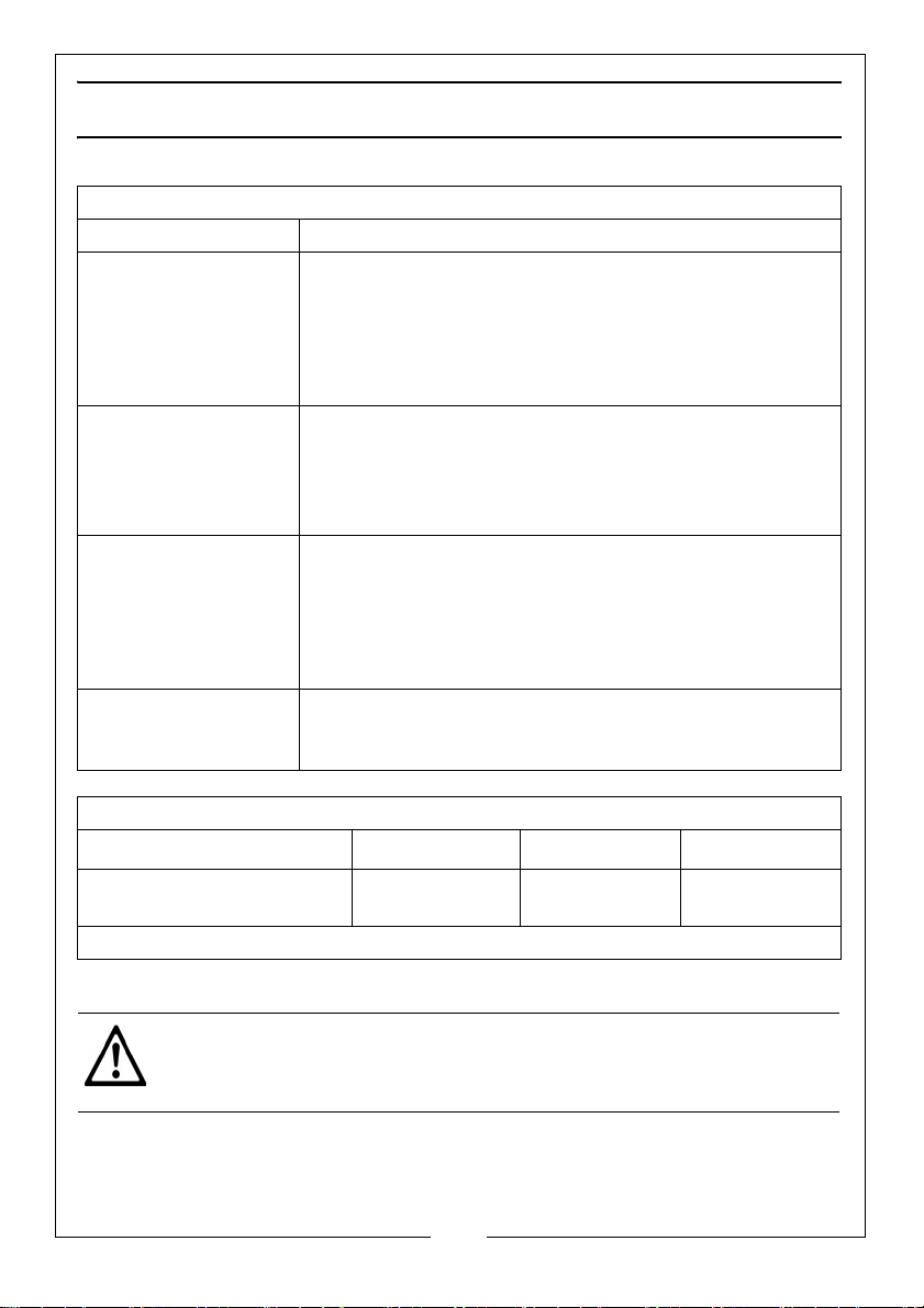
METER READING
LOAD TEST BATTERY CONDITION
OK (Green) Battery capacity is OK. Battery may or may not be
fully charged. Check specific gravity of battery to
determine state of charge. If specific gravity is less
than full charge, check for electrical drain or possible
charging system trouble. Recharge battery to full
level.
Weak or Bad, But
Needle is Steady
(Yellow or Red)
Weak or Bad, But
Needle is Falling
(Yellow or Red)
Charging System
(White)
Battery capacity is not satisfactory. Battery may be
either defective or not fully charged. Check specific
gravity to determine which condition exists. If
charging does not bring specific gravity to full charge
level, battery should be replaced.
Battery may be defective or very run down. Release
load switch and note voltmeter reaction. Voltage
recovery to 12 volt or above within seconds indicates
defective battery. Slow voltage recovery indicates
run down condition. For best results, check specific
gravity.
If the display meter needle reads OK charging system
Is functional. If it falls on the low red or high red areas,
charging system may be malfunctioning.
TEMPERATURE COMPENSATION
Battery temperature
Decrease battery rating
by:
CAUTION: TO PREVENT OVERHEATING, ALLOW TESTER TO COOL FOR 5
MINUTES BEFORE DEPRESSING THE LOAD SWITCH AGAIN IF FURTHER
TESTING IS REQUIRED.
Parts & Service: 020 8988 7400 / E-mail: [email protected] or [email protected]
°F (-7°C) 0°F (-18°C) -20°F (-29°C)
+20
1 STEP 2 STEPS 3 STEPS
1 STEP = 50 Cranking Amps
4
Page 5
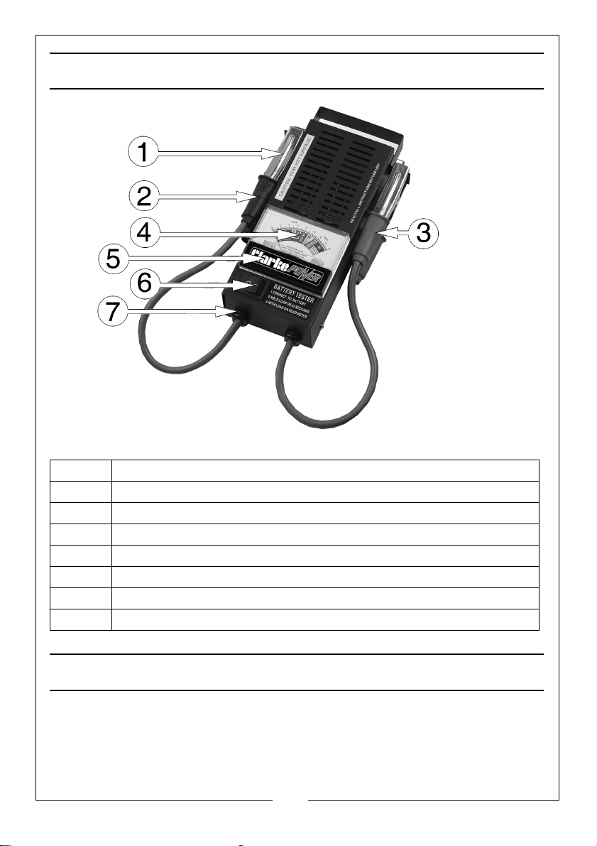
SPARE PARTS LIST
ITEM DESCRIPTION
1 Crocodile Clip
2 Sleeve Black (handle) - Negative
3 Sleeve Red (handle) - Positive
4Gauge Assy
5Gauge Cover
6LOAD ‘On’ Switch
7 Plastic Grommet
MAINTENANCE
• As the metal clamps are liable to come into contact with battery
electrolyte, it is advisable to wipe them clean and dry after use, and
apply a thin film of silicon grease to prevent the possibility of corrosion.
5
Parts & Service: 020 8988 7400 / E-mail: [email protected] or [email protected]
Page 6
SPECIFICATION
Model Number CVT2
Cable length (including Clamps) 460 mm
Product Dimensions: (L x W x H) 280 x 160 x 75 mm
Weight 1.1 kg
Part Number 6260103
6
Parts & Service: 020 8988 7400 / E-mail: [email protected] or [email protected]
Page 7
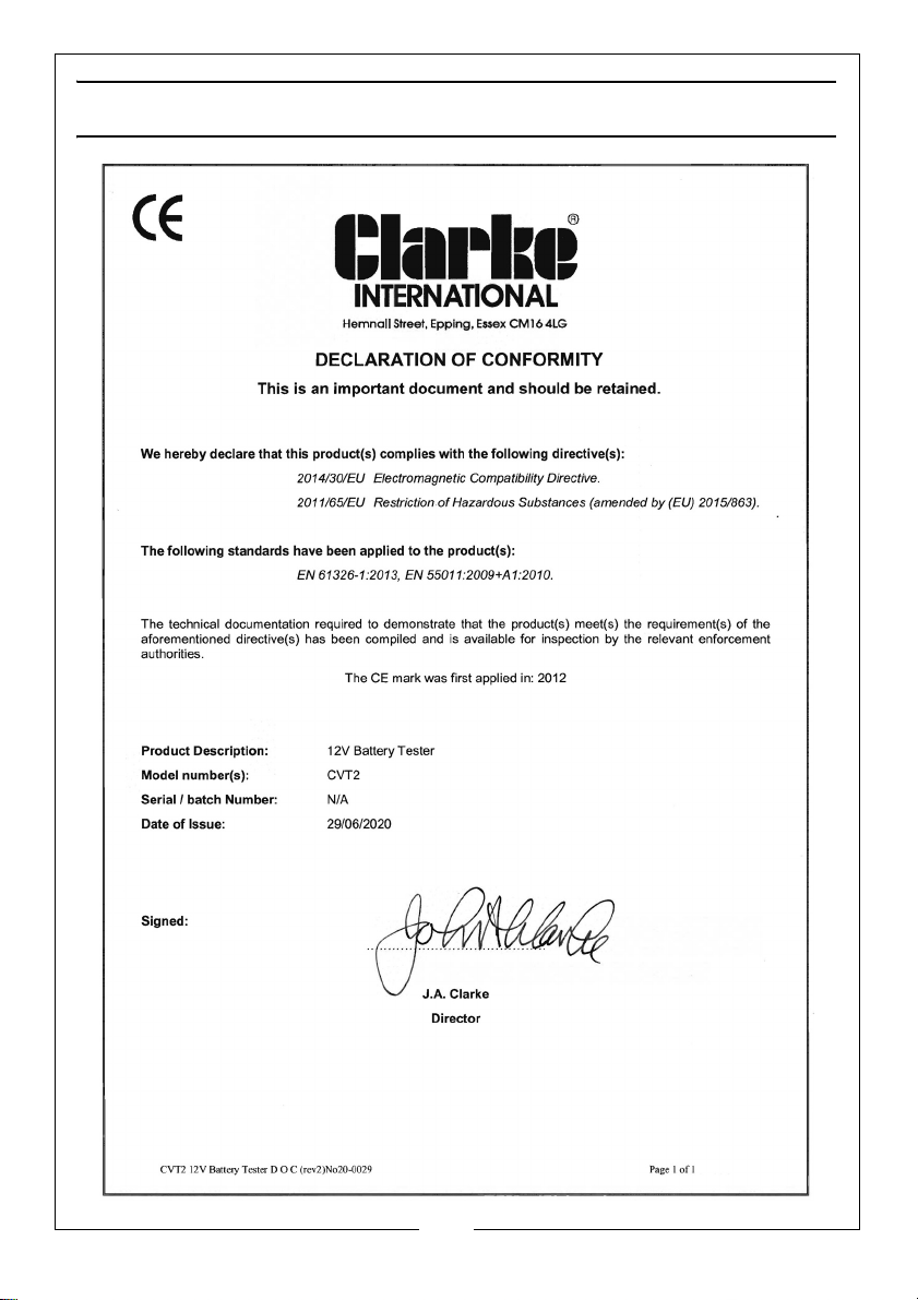
DECLARATION OF CONFORMITY
7
Parts & Service: 020 8988 7400 / E-mail: [email protected] or [email protected]
Page 8

 Loading...