

Page 1
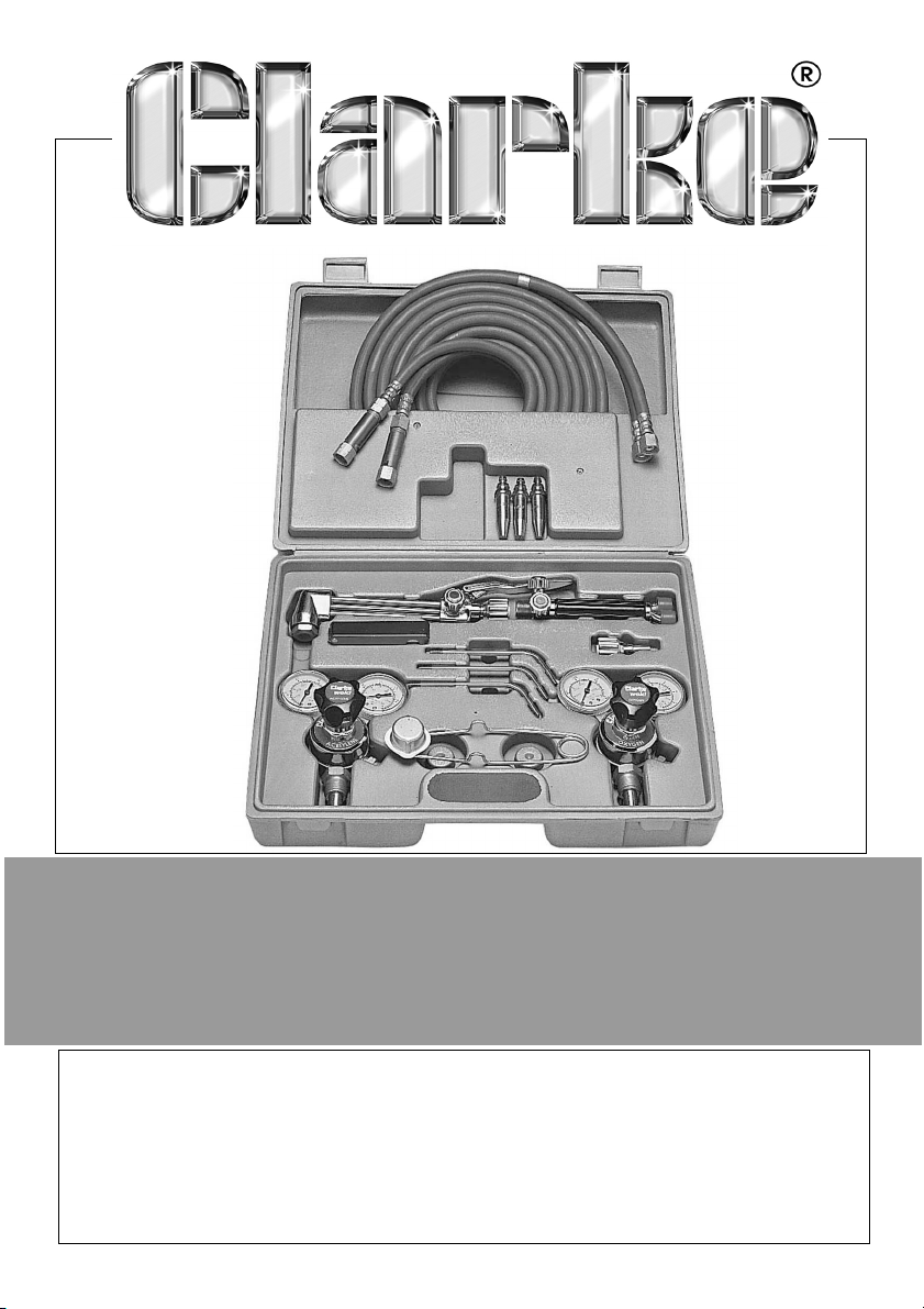
WELDING KIT
MODEL CGW1
PART NO: 6000670
USER INSTRUCTIONS
ORIGINAL INSTRUCTIONS GC0917 iSSUE 2
Page 2
INTRODUCTION
Thank you for purchasing this CLARKE Welding Kit.
Before attempting to use this product, please read this manual thoroughly and
follow the instructions carefully. In doing so you will ensure the safety of yourself
and that of others around you, and you can look forward to your purchase
giving you long and satisfactory service.
Please note, these instructions are designed to aid you in the basic principles
of welding, flame cutting, brazing, silver soldering, heating and the safe use of
gases, regulators and torches, they are NOT a definitive instruction manual.
With practice, a beginner can become proficient in the art of gas welding
and flame cutting. Once acquired, this skill will prove to be very useful and
possibly profitable.
GUARANTEE
This product is guaranteed against faulty manufacture for a period of 12
months from the date of purchase. Please keep your receipt which will be
required as proof of purchase.
This guarantee is invalid if the product is found to have been abused or
tampered with in any way, or not used for the purpose for which it was
intended.
Faulty goods should be returned to their place of purchase, no product can
be returned to us without prior permission. This guarantee does not effect your
statutory rights.
GENERAL SAFETY PRECAUTIONS
IMPORTANT: In addition to the following precautions, you should read, and
fully comply with, all instructions and safety precautions that were supplied
with your TIG Welder. Please keep these instructions in a safe place for
future reference.
1. NEVER point the torch at any person or animal.
2. NEVER touch the nozzle unless the welder is switched OFF and the nozzle
has been allowed to cool off.
3. NEVER connect, disconnect, or attempt to service the torch, unless the
welding machine is switched OFF and disconnected from the mains
supply..
2
Parts & Service: 020 8988 7400 / E-mail: [email protected] or [email protected]
Page 3

4. When welding, users and bystanders must ALWAYS use a protective
headshield fitted with the correct shade of lens. Failure to do so can cause
serious damage to your eyes.
5. ALWAYS learn the product applications, limitations and the specific
potential hazards peculiar to it. Read and become familiar with the entire
operating manual.
6. ALWAYS check for damage. Before using the equipment, any damaged
part should be checked to ensure that it will operate properly and perform
its intended function. Any damage should be properly repaired or the part
replaced. If in doubt, DO NOT use the product. Consult your local dealer.
7. ALWAYS wear safety goggles, manufactured to the latest European Safety
Standards.
8. ALWAYS keep the work area clean. Cluttered areas and benches invite
accidents.
9. ALWAYS ensure that adequate lighting is available. A minimum intensity of
300 lux should be provided. Ensure that lighting is placed so that you will
not be working in your own shadow.
10. ALWAYS keep children away. All visitors should be kept a safe distance
from the work area, especially whilst welding.
11. ALWAYS concentrate on the job in hand, no matter how trivial it may seem.
Be aware that accidents are caused by carelessness due to familiarity.
12. ALWAYS keep your proper footing and balance at all times - don’t
overreach. For best footing, wear rubber soled footwear. Keep floor clear
of oil, scrap wood, etc.
13. ALWAYS prepare the work area before welding/cutting, work in a well
ventilated area.
14. ALWAYS wear the correct safety wear specified for welding, i.e. welding
goggles, welding gloves, apron and safety shoes etc.
ADDITIONAL SAFETY PRECAUTIONS
ALWAYS handle gas cylinders with care, chain or otherwise secure cylinders to
a permanent fixture. Take care when moving.
ALWAYS use acetylene cylinders in an upright position, NEVER lying down.
ALWAYS store gas cylinders and related equipment according to local
regulations.
ALWAYS ensure all hoses and connections are tight and leak free. Test for
leaking joints etc using soapy water, NEVER use an open flame. DO NOT
overtighten connections.
3
Parts & Service: 020 8988 7400 / E-mail: [email protected] or [email protected]
Page 4
ALWAYS ensure the non return valves/flash back arrestors supplied are fitted to
both lines.
ALWAYS use recommended pressure settings. Improper settings are wasteful.
Extreme pressure build up in regulators is a warning to have them checked
and repaired.
ALWAYS “crack” the oxygen cylinder valve before installing the regulator, this
is carried out by briefly opening the valve and allowing the escaping oxygen
to clear away any dust which could damage the regulator.
ALWAYS prime oxygen and acetylene lines separately before lighting up, this
will help prevent incorrect mixing of gases.
NEVER use oxygen to blow off work or clothing. Pure oxygen supports
combustion and a spark can ignite oxygen-saturated clothing.
NEVER use oil or grease on the equipment, oil and grease is easily ignited and
burns violently in the presence of oxygen.
NEVER work with damaged/leaking hoses and equipment, check for leaks
using soapy water, any defects must be rectified before continuing.
INVENTORY
The welding kit comprises the following items:
Item Qty
Moulded Carry Case
Oxygen Regulator
Acetylene Regulator
Welding Torch/Handle
Welding Nozzle Adapter
Cutting Torch
Welding Nozzles
Cutting Nozzles
Hoses
Non Return Valve/Flashback Arrestor (oxygen)
Non Return Valve/Flashback Arrestor (acetylene)
Spark Igniter
Tip Cleaners 1
1
1
1
1
1
1
3
3
2
2
2
1
4
Parts & Service: 020 8988 7400 / E-mail: [email protected] or [email protected]
Page 5
SETTING UP INSTRUCTIONS
WARNING: ENSURE THERE ARE NO NAKED FLAMES OR SPARKS WHICH
COULD IGNITE WHEN PRIMING OR PURGING THE HOSES ETC. ENSURE A
FIRE EXTINGUISHER IS ALWAYS AT HAND IN CASE OF ACCIDENTS.
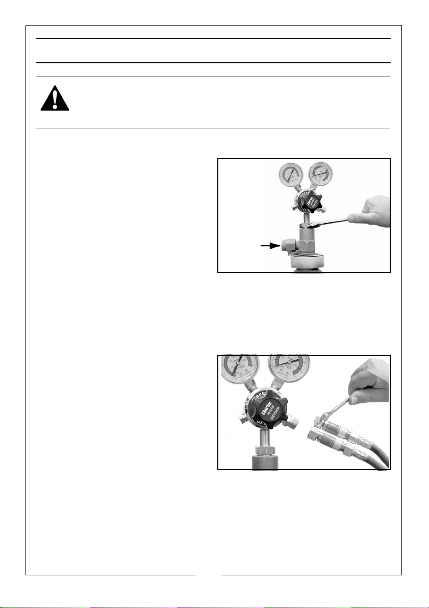
ATTACHING THE REGULATORS (FIG 1)
Open the oxygen cylinder valve
(arrowed) briefly to blow out any dust
etc, ensure the valve is fully closed
before continuing.
Attach the oxygen regulator (Blue)
and tighten the connector using
25mm open ended spanner.
DO NOT overtighten.
Repeat the above procedure for
attaching the acetylene regulator
(Red).
NOTE: The acetylene connections are all left handed whilst the oxygen
connections are all right handed.
ATTACHING THE HOSES (FIG 2)
Connect the hoses (complete with
flashback arrestors on each one) to
the regulator outlets, blue to the
oxygen outlet marked ‘OUT’ and red
to the acetylene outlet marked ‘OUT’,
again observing left and right
handed threads.
Tighten both connectors using a
19mm open ended spanner.
DO NOT overtighten.
5
Parts & Service: 020 8988 7400 / E-mail: [email protected] or [email protected]
Page 6
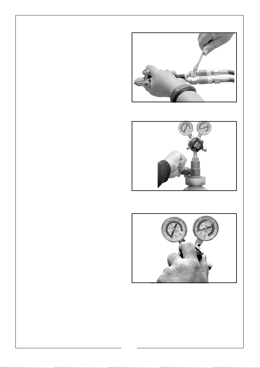
ATTACHING THE TORCH (FIG 3)
Attach the acetylene hose complete
with flame arrestor (Red) to the torch
inlet valve marked ‘GAS’ and the
oxygen hose complete with flame
arrestor (Blue) to the torch inlet valve
marked ‘OX’.
Tighten both connectors using a
19mm open ended spanner, DO NOT
overtighten. Ensure both valves are
closed fully before continuing.
OPENING THE VALVES (FIG 4)
Ensure both regulator knobs are
opened fully (turned anticlockwise),
carefully using cylinder key, slowly
open both cylinder valves in turn,
starting with the oxygen one.
ADJUSTING THE OPERATING PRESSURE (FIG 5)
When adjusting the operating
pressures, refer to the relevant table
on page 9, depending whether
welding or cutting etc.
Adjust the operating pressure on both
cylinders by turning the regulator
valve knobs in a clockwise direction,
observe the low pressure gauge
(Right Hand Gauge) until the gauge
reading is at the correct pressure
setting.
NOTE: The left hand gauge shows the pressure in the cylinder and is not
adjustable. This is an indication how much oxygen/acetylene
remains inside the cylinder.
6
Parts & Service: 020 8988 7400 / E-mail: [email protected] or [email protected]
Page 7
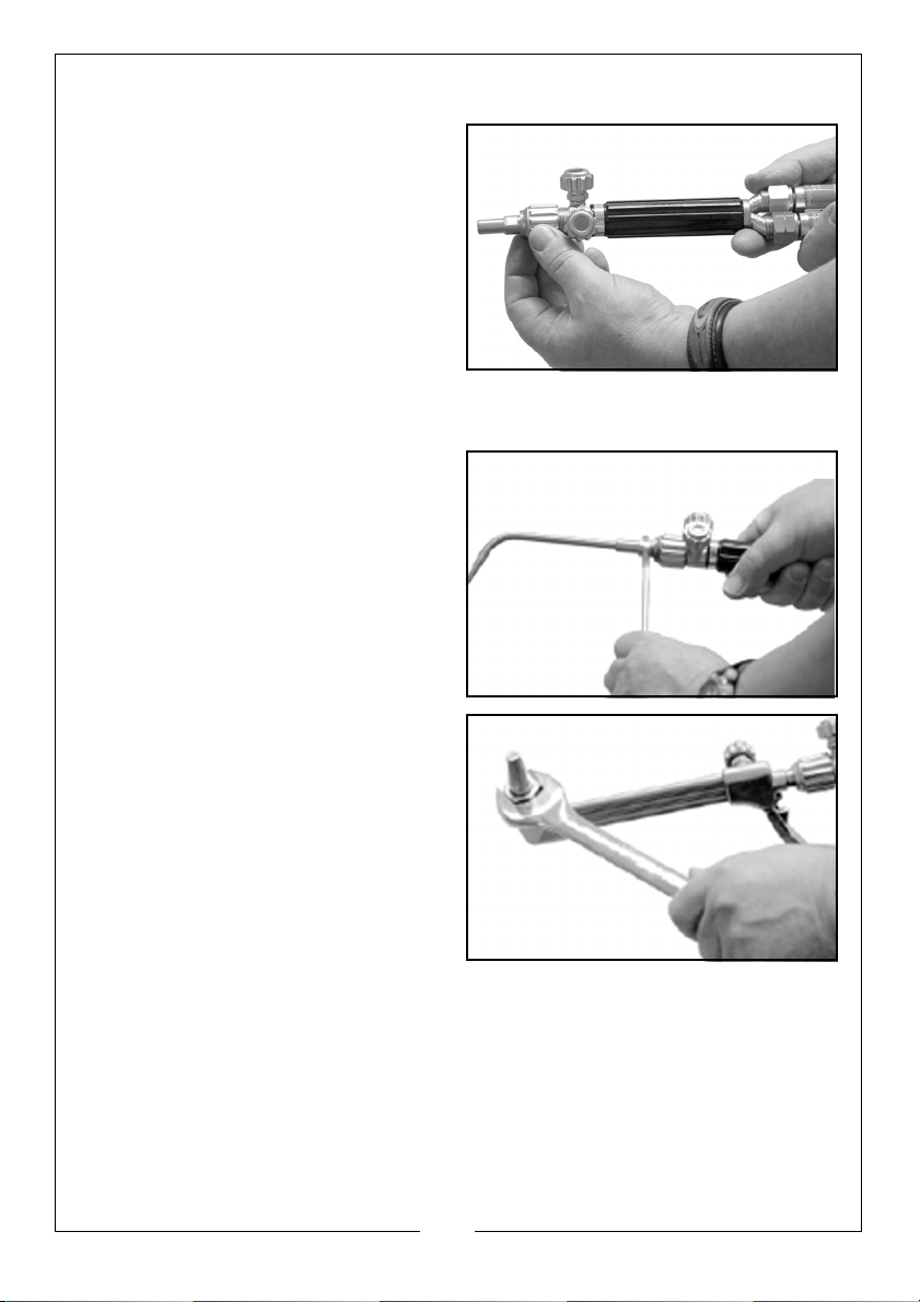
INSTALLING THE CUTTING/WELDING NOZZLE (FIG 6, 7 & 8)
WELDING
Remove the cutting torch if fitted,
attach the welding nozzle adapter to
the welding torch/handle, tightening
hand tight only.
Select the required welding nozzle
and screw into the adapter. To
prevent the adaptor from turning,
hold in position with a 11mm open
ended spanner. Adjust the nozzle
position by turning to the desired position using an 11mm open ended
spanner on the nozzle connector.
CUTTING
Remove the welding nozzle and
nozzle adapter if fitted. Attach the
cutting torch to the welding torch/
handle, tighten the securing collar by
hand, ensuring the operating lever
does not foul on the valve knobs etc.
Remove the cutting nozzle securing
nut, select the required nozzle and
place into the securing nut. Screw
into the cutting torch and lock in
place using a 23mm open ended
spanner.
DO NOT overtighten.
7
Parts & Service: 020 8988 7400 / E-mail: [email protected] or [email protected]
Page 8
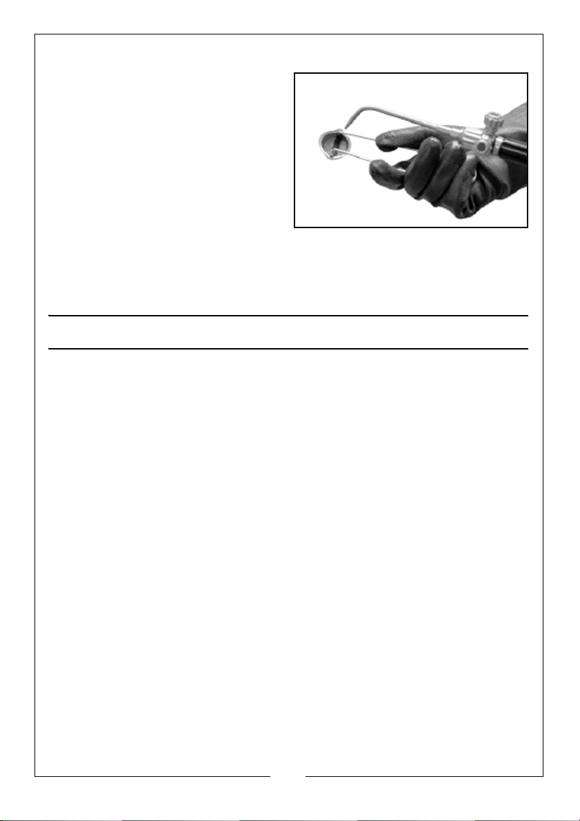
LIGHTING THE TORCH (FIG 9)
Open the torch acetylene valve
approximately one half turn and
ignite using the supplied spark igniter.
Open the torch valve until the flame
stops excessive smoking and leaves
the end of the nozzle tip about 3mm,
then reduce slightly to bring the
flame back to the tip.
Open the torch oxygen valve until a
bright inner cone appears in the
flame.
The point at which the feathery edges of the flame disappear and a sharp
inner cone is visible is called the “Neutral Flame”.
BASIC WELDING PROCEDURES
Gas welding is a method of joining similar metals by heating the adjacent
surfaces to melting point with an oxyacetylene flame and allowing the two
parts to fuse together with a filler metal being required on materials 5mm thick
or more. The resulting weld is as strong as the parent metal.
All metal to be joined should be thoroughly cleaned before welding. Oil,
grease, rust, scale or other impurities affect the weld quality and the tensile
strength. Metal of 5mm and over should be bevelled before attempting to
weld and when bevelled edges are to be joined. A filler rod of the same
material must be used.
The table below is a guide only showing recommended, oxygen and
acetylene pressures relating to the size of the material to be welded etc.
If a too larger tip is used and the flame is softened, the tip heats up
unnecessarily and is often accompanied by a popping noise which splatters
the weld puddle. Too hot a flame burns the steel and too small a flame is not
big enough to get the job done.
WELDING ROD
Welding rods are available in various sizes with the most common being
1.6mm, 2.4mm and 3.2mm. They are also available for welding mild steel, cast
iron and aluminium.
The size of rod will be determined by the type of weld, the metal thickness and
the amount of filler metal required.
8
Parts & Service: 020 8988 7400 / E-mail: [email protected] or [email protected]
Page 9
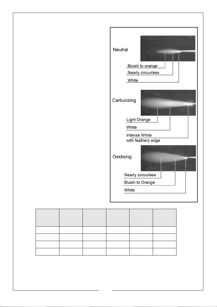
WELDING FLAME
A neutral flame is used for almost all
gas welding. The oxyacetylene flame
consumes all oxygen in the welding
area which leaves an
uncontaminated weld area and a
weld of maximum strength.
An oxidizing flame is rarely used.
A carbonizing flame is used mainly for
flame hardening and brazing.
Metal
Thickness
(mm)
1.6mm 2 1.6mm 3 3 1
2.4mm 5 2.4mm 5 5 1
3.2mm 5 3.2mm 5 5 1
6.4mm103.2mm992
Tip Size Rod Size Oxygen
Pressure
(PSI)
Acety-
lene Pres-
sure (PSI)
Number
of Passes
9
Parts & Service: 020 8988 7400 / E-mail: [email protected] or [email protected]
Page 10
WELDING - PRACTICES AND EXERCISES
Gas welding is not a difficult art. The following exercises of torch movement
are good practice and make subsequent welding easy.
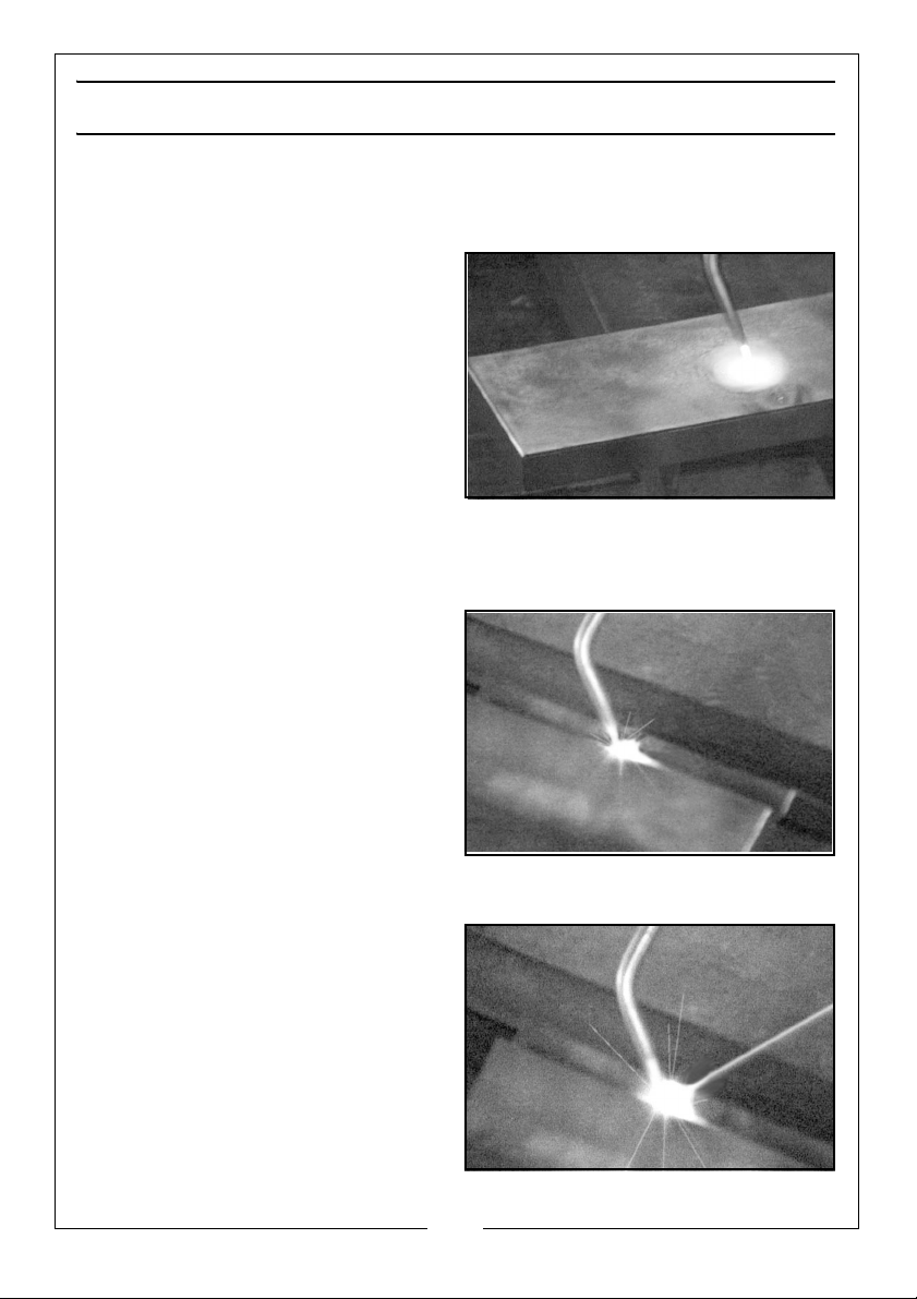
EXERCISE 1
Using a small welding nozzle and
correct pressures (see table on page
9), point the flame directly onto the
steel (3.2mm stock recommended)
with the flame cone just above the
metal surface. When a puddle
begins to form, slowly move the torch
back and forth to move the puddle
across the steel. This action has to be
done slowly as it is necessary to have
good penetration, which comes from
a deep puddle. When moving the puddle, it is helpful to lean the nozzle at an
angle of approx 45º away from the direction you want the puddle to move.
EXERCISE 2
Place two pieces of 3.2mm steel
together as shown. Make the puddle
again with a back and forth torch
motion, move the puddle along the
seam. Move the torch slowly for a
good penetration. This can be
checked by turning the parts over.
The penetration should be visible
from the bottom side. Test the weld
strength by attempting to pull the
pieces apart.
EXERCISE 3
Repeat exercise 2, but add welding
rod this time. While the flame is
directed at the steel to form the
puddle, put the rod into the flame.
when it becomes red, maintain this
temperature by moving it in and out
of the flame. Once the weld is started
dip the rod into the puddle, the rod
will melt and build up the weld so
that the top is rounded instead of
concave. Remember, welding rod is
10
Parts & Service: 020 8988 7400 / E-mail: [email protected] or [email protected]
Page 11
necessary on all double joints and once the you become an experienced
welder, you will prefer to use rod on all welds, regardless of how thin the steel
to be welded.
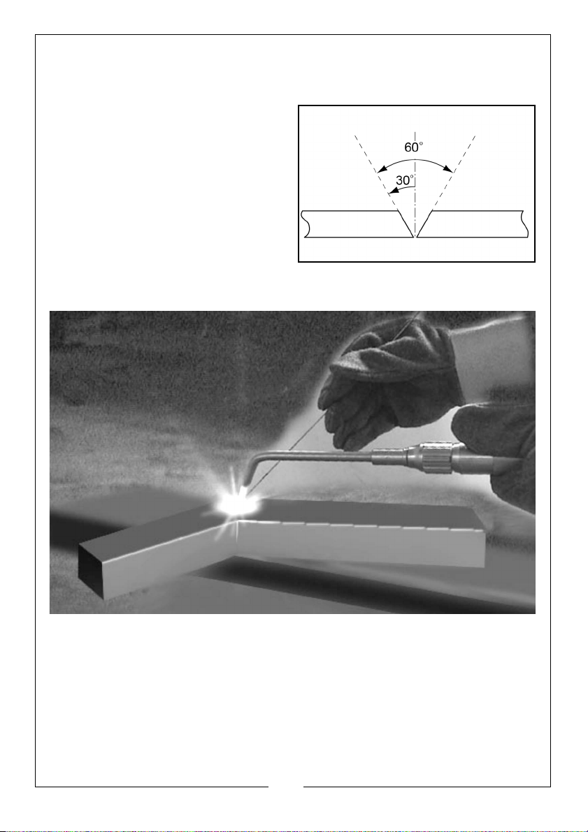
Material of 5mm or thicker should be
bevelled before welding. A 30º bevel
on each piece is the recommended
angle. This is necessary to obtain the
best penetration possible through the
entire thickness. A rod is necessary on
all welds with bevelled edges. Once
the torch movement and puddle
control are mastered, you will be
able to make vertical, horizontal and
flat welds with confidence.
BRAZING
Brazing differs from welding because the two pieces of metal to be joined are
not fused together. The brazing rod melts at a lower temperature than the
parent metal and the braze strength comes from the surface overlay of the
brazing rod.
The advantage of brazing over welding is that it is the best way to join
dissimilar metals, or repair cast iron. Almost any two metals can be joined by
brazing, excluding aluminium and magnesium.
Brazing is separated into two types, depending on the type of rod used,
bronze or silver. Bronze is less expensive than silver and should be used when
11
Parts & Service: 020 8988 7400 / E-mail: [email protected] or [email protected]
Page 12
the fit between the two metals to be joined is not close. The metals must be
cleaned thoroughly before attempting to braze, gently play the flame onto
both parts until they become a dull reddish colour. Both pieces must be of
equal temperature otherwise the braze will flow to the hottest piece. Heat the
rod by placing it in the flame, then dip it into the flux (note the heat causes the
flux to melt and stick to the rod). If a prefluxed rod is used, this heating and
dipping step may be eliminated. Once the rod is fluxed, and the metals are
heated to the correct temperature, touch the rod to the joint, the rod melts
and flows over the heated area, depending on the size of the joint, it may be
necessary to dip the rod into the flux again. Abundant flux must be used,
otherwise the molten rod will not stick to the metals being joined.
Silver brazing is a little faster than bronze brazing. This is because silver melts at
a much lower temperature and less heat is required. However, the joint must fit
tightly together. Bronze bridges a gap much better than silver. Instead of
putting flux on the silver rod, the joint should be painted with flux. The way to
determine when the metals are at the correct temperature is to watch the flux
as it starts to bubble; as it does so it is time to apply the silver. The silver melts as
it touches the hot metal and the molten silver flows over the fluxed area.
FLAME CUTTING
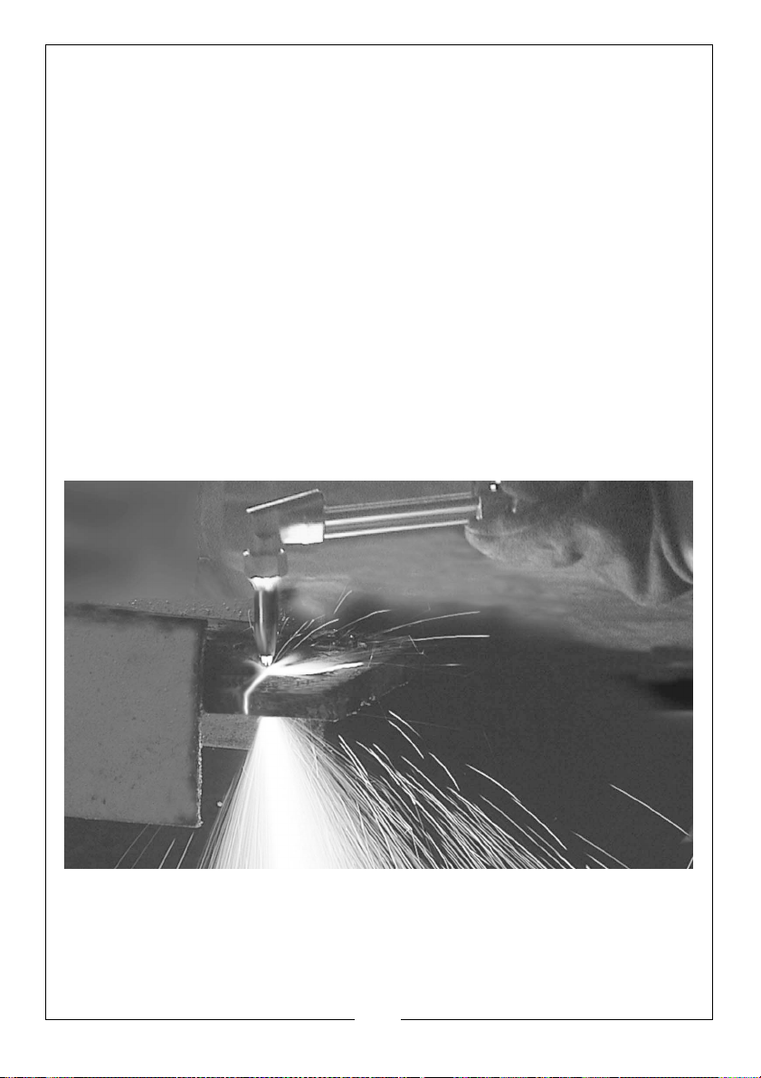
Flame cutting is a simple process that can be quickly mastered. Only steel can
be cut with the oxyacetylene method, since cast iron, stainless steel,
aluminium, brass and other ferrous metals do not burn the way that steel does.
The way to cut steel is to heat it to its kindling temperature (a reddish colour),
then burn it with pure oxygen. A cutting torch provides both the preheat
12
Parts & Service: 020 8988 7400 / E-mail: [email protected] or [email protected]
Page 13
flames and pure oxygen cutting stream. Acetylene and oxygen are
combined in the torch head and burn at the torch tip with a 6000ºF flame;
these are the preheat flames. The centre hole in the cutting tip is the cutting
oxygen hole, through which, pure oxygen, which is not mixed with acetylene,
flows to cut the steel after the metal is sufficiently preheated.
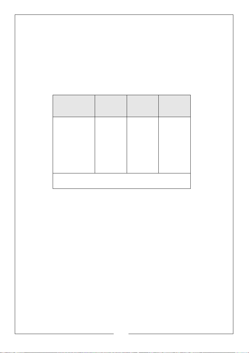
CUTTING NOZZLES
Cutting nozzles are available in a wide range of sizes, the correct size being
determined by the steel thickness. Refer to the table below for correct
pressures and tip sizes.
Metal
Thickness
Tip Size Oxygen
Pressure
Acetylene
Pressure
(P.S.I)
3.2 - 6.4mm
9.6mm
12.7 - 25.4mm
50.8mm
76.2 -101.6mm
127 - 152mm
00
25 - 35
0
1
2
3
4
25 - 35
35 - 45
45 - 50
45 - 55
55 - 65
Tip size and pressure may vary according to
operator choice. The table is a guide only.
6
6
6
6
6
6
13
Parts & Service: 020 8988 7400 / E-mail: [email protected] or [email protected]
Page 14
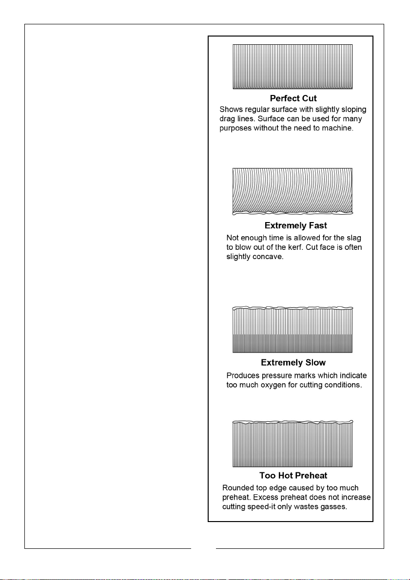
Once the correct nozzle is tightly
secured in the cutting torch, correct
pressure set on the regulators and the
flame is adjusted to a neutral one,
follow these simple procedures to cut
steel using oxyacetylene.
1. Before lighting, open the oxygen
valve on torch handle, one full
turn. Make all oxygen adjustments
with valve on the cutting
attachment.
2. Move the flame to the edge of
the steel and position the preheat
cone just above the metal.
3. When the steel becomes red,
slowly depress the cutting lever to
release the oxygen stream to cut
through the steel.
4. Slowly move the torch in the
direction of the cut. The correct
speed is accompanied by a
sputtering sound and a steady
stream of sparks. This results in a
clean, slag free cut with square
top and bottom edges.
5. Too fast a movement does not
allow time for the oxygen stream
to cut all the way through the
metal. Slag fills the kerf and the
two pieces are not severed.
6. Too slow a movement leaves a
rounded top edge with slag
sticking to the bottom of the
metal.
7. The size of the preheat flame
determines how quickly the cut
can be started. Often, a small
preheat flame is desirable to
conserve gases and prevent
melting of the top edges.
14
Parts & Service: 020 8988 7400 / E-mail: [email protected] or [email protected]
Page 15
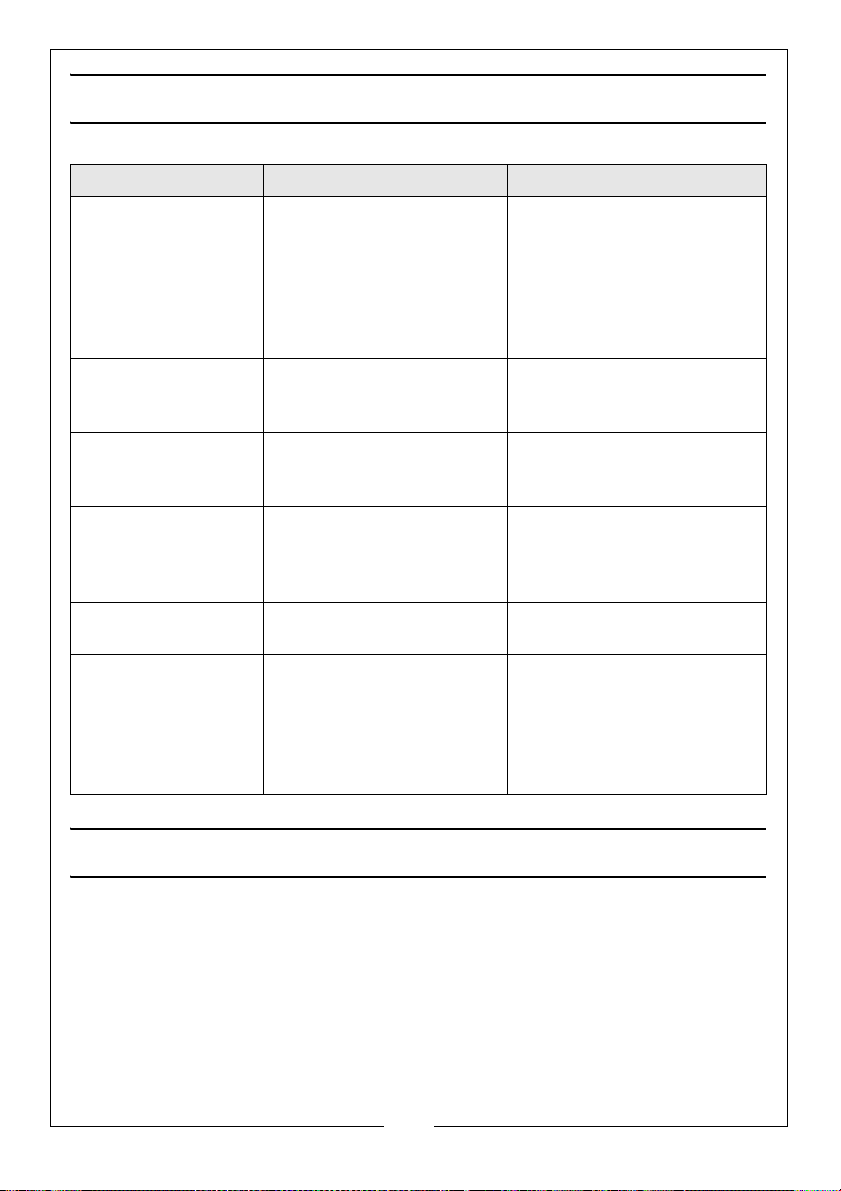
TROUBLESHOOTING
Problem Probable Cause Remedy
Welding tip popping Tip is operated at too low
heat.
Increase pressures, consult
tip table (page 13).
Nozzle too large
Tip too close to work
Flames not clearly
defined, smooth or
even.
Regulator not
holding constant
pressure.
Cutting tip popping. Nozzle loose
Difficult to light. Too much pressure. Consult pressure table.
Flame changes
during cutting.
Dirty tip Clean with tip cleaner or
Defective seat. Return unit for replacement.
Seat nicked
Oxygen needle valve on
torch handle partly
closed.
Oxygen cylinder almost
empty.
Use next smallest size nozzle
Move tip further from the
work area.
replace nozzle.
Tighten nozzle nut
Replace nozzle
(page 9).
Fully open oxygen valve.
Replace cylinder with a full
one.
ACCESSORIES
A wide range of tools and accessories is available from your nearest CLARKE
dealer, for further information, contact your nearest dealer, or telephone
CLARKE International Sales department on 01992 565300.I
IMPORTANT: The use of parts other than CLARKE replacement parts may
result in safety hazards, decreased tool performance and may invalidate
your warranty.
15
Parts & Service: 020 8988 7400 / E-mail: [email protected] or [email protected]
Page 16
 Loading...