

Page 1
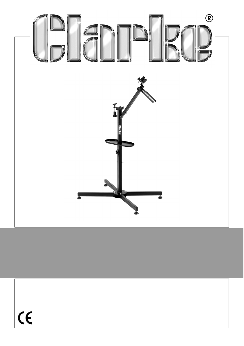
BICYCLE REPAIR STAND
MODEL NO: CBWS
PART NO: 7610197
OPERATION & MAINTENANCE
INSTRUCTIONS
LS1213
Page 2
INTRODUCTION
Thank you for purchasing this CLARKE product.
Before attempting to use this product, please read this manual thoroughly and
follow the instructions carefully. In doing so you will ensure the safety of yourself
and that of others around you, and you can look forward to your purchase
giving you long and satisfactory service.
GUARANTEE
This product is guaranteed against faulty manufacture for a period of 12
months from the date of purchase. Please keep your receipt which will be
required as proof of purchase.
This guarantee is invalid if the product is found to have been abused or
tampered with in any way, or not used for the purpose for which it was
intended.
Faulty goods should be returned to their place of purchase, no product can
be returned to us without prior permission.
This guarantee does not effect your statutory rights.
SPECIFICATION
Dimensions 430 x 620 x 1060 mm
Weight 4.6 kg
2
Parts & Service: 020 8988 7400 / E-mail: [email protected] or [email protected]
Page 3
ASSEMBLY
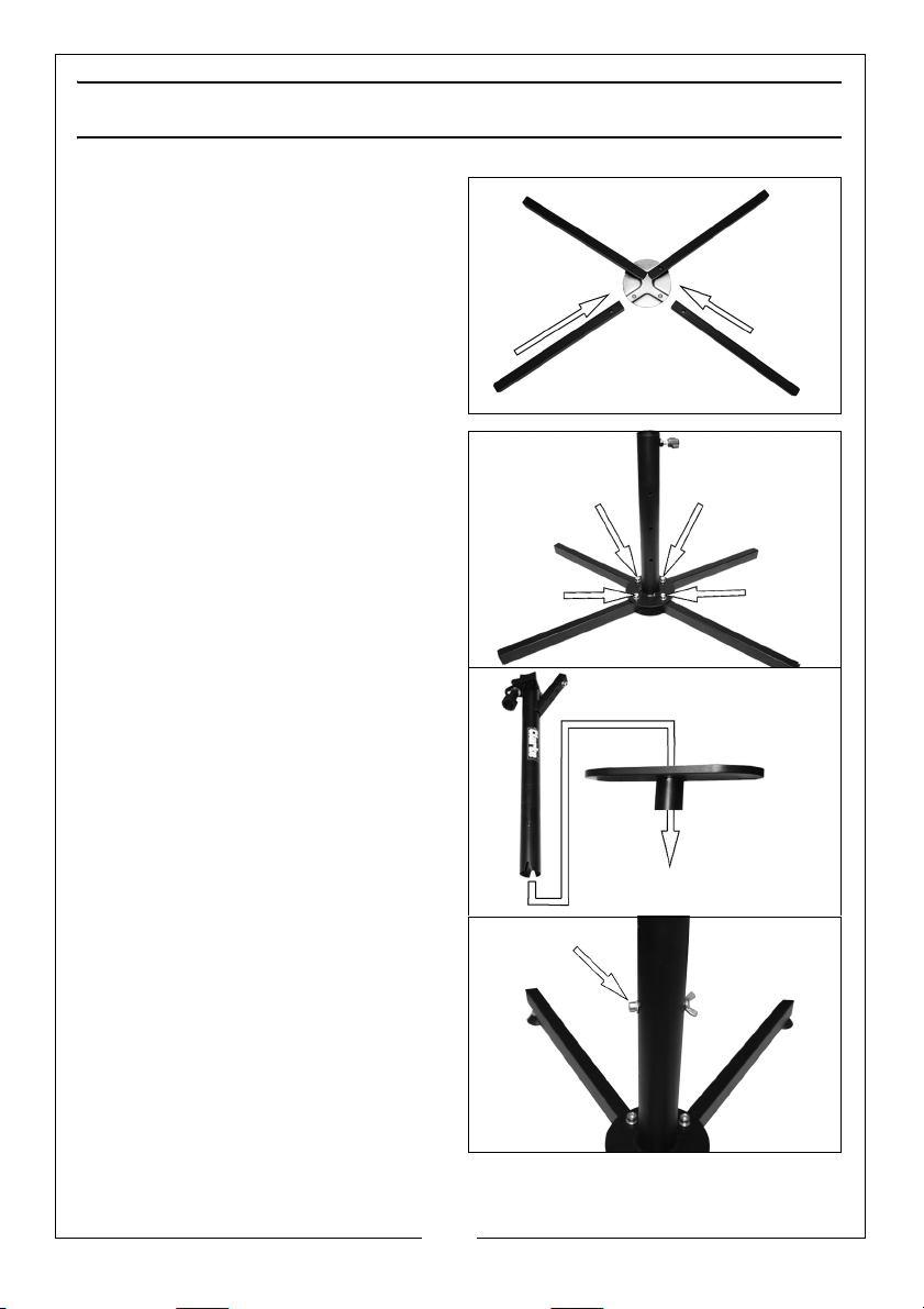
1. Place the four legs onto the base
plate as shown.
• On one end of the leg there
are 2 holes, this end should go
towards the centre of the base
plate
• On the other end of the leg
make sure that the hole is
pointing towards the floor.
2. Place the lower column onto the
legs and secure using the four
long bolts and spring washers
provided.
3.
4. Slip the tool tray on to the upper
column as shown.
5. Place the spring washer and
washer onto the long bolt.
6. Pass the bolt through one of the
holes in the lower column as
shown.
• The holes provide three
different working heights.
7. Secure using the wing nut.
3
Parts & Service: 020 8988 7400 / E-mail: [email protected] or [email protected]
Page 4
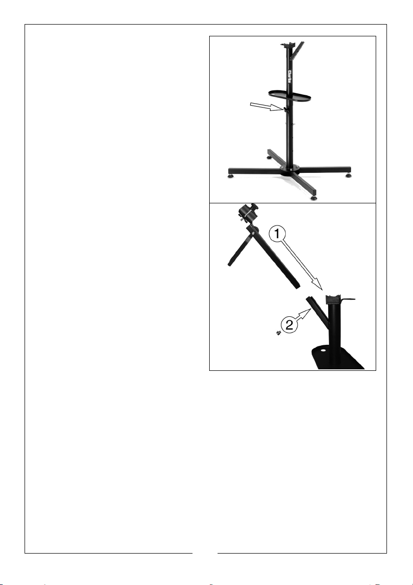
8. Slide the upper column into the
lower column until it is resting on
the bolt inserted previously.
9. Tighten the adjustable knob
clockwise until hand tight.
10. Slide the bike frame holder
assembly onto the square tube
located on the upper column.
11. Fasten with small hex bolt
provided.
• You have three locations to
choose from depending on the
size of the bicycle.
4
Parts & Service: 020 8988 7400 / E-mail: [email protected] or [email protected]
Page 5
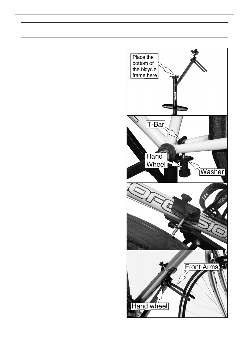
USING THE STAND
1. Place the lowest point of the
bicycle frame onto the stand.
2. Pass the T-bar through the bicycle
frame as shown and secure with
the washer and hand wheel.
NOTE: The gear assembly is not
shown for clarity.
3. Clamp the sloping crossbar to the
stand as shown.
4. Place the front arms either side of
the front wheel.
5. Tighten the hand wheel to hold
them in place.
5
Parts & Service: 020 8988 7400 / E-mail: [email protected] or [email protected]
Page 6
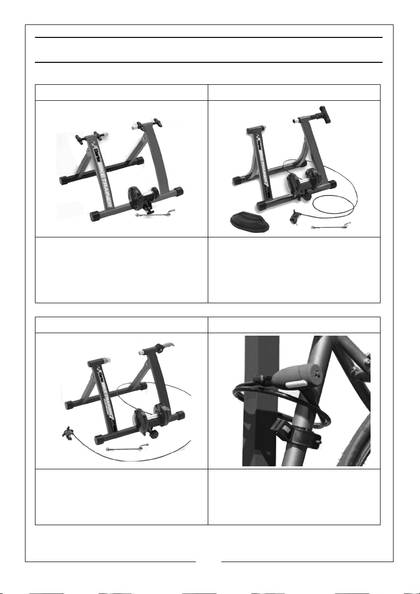
ACCESSORIES
BIKE TRAINER - CCTS BIKE TRAINER - CCTI
•Magnetic Resistance
•Folds Flat For Easy Storage
•Part No. 4510001
•7 Level Magnetic Resistance
•Folds Flat For Easy Storage
•Contains A Front Wheel Base For Extra
Stability
•Part No. 4510005
BIKE TRAINER - CCTQR SPIRAL BIKE LOCK - CHT727
•7 Level Magnetic Resistance
•Quick Release
•Folds Flat For Easy Storage
•Part No. 4510003
• PVC Coated Steel Cable
• Quick Release Bracket
•Lightweight
•Part No. 1081727
6
Parts & Service: 020 8988 7400 / E-mail: [email protected] or [email protected]
Page 7

Page 8
 Loading...