

Page 1
WIRELESS WEATHER STATION
MODEL NO: WS100
PART NO: 4501002
OPERATION & MAINTENANCE
INSTRUCTIONS
LS0309
Page 2
INTRODUCTION
Thank you for purchasing this CLARKE Wireless Weather Station.
Before attempting to use this product, please read this manual thoroughly and
follow the instructions carefully. In doing so you can look forward to your
purchase giving you long and satisfactory service.
GUARANTEE
This product is guaranteed against faulty manufacture for a period of 12
months from the date of purchase. Please keep your receipt which will be
required as proof of purchase.
This guarantee is invalid if the product is found to have been abused or
tampered with in any way, or not used for the purpose for which it was
intended.
Faulty goods should be returned to their place of purchase, no product can
be returned to us without prior permission.
This guarantee does not effect your statutory rights.
IN THE BOX
1. 1 x Base station
2. 1 x Remote sensor w
3. 1 x Instruction manual
ith mounting bracket
ENVIRONMENTAL PROTECTION
BATTERY DISPOSAL
Please ensure batteries are disposed of safely. Never dispose of batteries in
th
e fire or with household waste. Check with your local authority for disposal
regulations.
2
Page 3
OVERVIEW
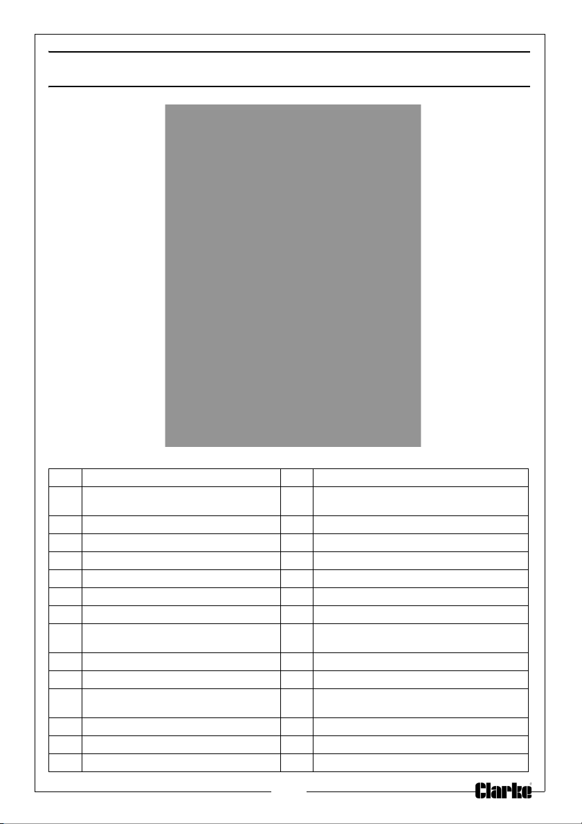
1 Daylight Saving Time indicator 16 Outdoor humidity display
2 Radio Controlled Time indicator 17 Outdoor temperature and humidity low
3 Time 18 Temperature display unit (C or F)
4 Radio Controlled Time Icon 19 Outdoor temperature display
5 Alarm ON indicator 20 General outdoor alarm icon
6 Day of week/ time zone 21 Weather forecast icon
7 Date 22 Weather tendency indicator
8 Indoor humidity display 23 Pressure with 24 hour history graph
9 Indoor temperature and Humidity Low
ar
m and high alarm
al
10 Indoor temperature display 25 Pressure low alarm
11 Temperature display units 26 Air pressure history graph (past 24 hours)
12 Indoor temperature and humidity
13 Remote sensor transmit signal indicator 28 Pressure display unit (inHg or hPa)
14 MIN/MAX information 29 Pressure alarm on indicator
15 Dew point temperature display 30 Low Battery Icon
m on indicator
alar
alar
m and high alarm
24 Pressure high alarm
27 Barometric air pressure
3
Page 4
SET UP
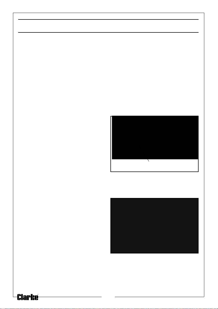
Battery compartment retaining screw
Fig 1
Fig 2
NOTE: Use good quality alkaline batteries and avoid rechargeable
batteries.
1. Have the indoor weather station and remote temperature sensor close
together during setup.
2. Place the batteries into the remote sensor first then into the weather
station. See below.
INSTALLING THE BATTERIES
REMOTE SENSOR (FIG 1)
Unscrew and remove the battery
1.
compartment retaining screw.
2. Remove the battery
compartment cover.
3.
Insert two alkaline AAA batteries
into the remote sensor.
NOTE: Make
4. Replace the battery compartment cover.
sure that you follow
the polarity diagram inside
the battery compartment.
INDOOR BASE STATION (FIG 2)
Remove the battery cover.
1.
2. Observing the correct polarity,
install three alkaline AA batteries.
3.
Replace the battery cover.
4. Do not press any buttons for at
least ten minutes
time for the weather station to
start receiving information from
the sensor,
• If successful the indoor weather station will show the outdoor
temperature and humidity.
This will allow
.
4
Page 5
• If the indoor weather station does not display these values after 1
minute, the signal search will try again every two hours until a signal is
found.
• Once the remote sensor temperature and humidity values are displayed
for 10 minutes you can place the sensor outdoors.
RADIO TIME SIGNAL
After the initial setup period, the weather station will start to search for a radio
time signal.
The time and date signal is sent by a highly accurate government-operated
atomic clock. The weather station will continually scan for the radio controlled
time signal each day.
• If reception is unsuccessful, then the radio time signal icon will not
appear and the manually entered time will be displayed. See page 9 for
instructions on how to enter the time manually.
• If reception has been successful, the radio time signal icon will be
shown and the received time and date will overwrite any manually set
time and date.
5
Page 6
MOUNTING
BASE STATION
• There is a folding stand at the
rear
of the base station, which
allows the unit to be stood onto
any flat surface.
• The base station may also be
wall mounted using the
hanging hole on the rear of the
unit.
NOTE: It is important to check that
the radio signal can be
received at the chosen location before permanently mounting
either of the units.
REMOTE SENSOR
NOTE: T
NOTE: Obstructions such as walls, concrete, and large metal objects will
1.
2. Clip the sensor into the wall
3.
o obtain acurate temperature r
remote sensor in direct sunlight. We recommend that you mount
the sensor on an outside north-facing wall.
reduce the transmitting range.
Use 3 screws to fix the wall bracket
to the wall.
bracket as shown.
The remote sensor will transmit the
outdoor temperature
humidity back to the weather
station.
and
eadings, do not mount the
6
Page 7
USING THE WEATHER STATION
Sunny
Cloudy
Partly Cloudy
Rain
WEATHER FORECASTING
The four weather icons Sunny, Partly Cloudy, Cloudy and Rainy represent the
weather types.
NOTE: Weather forecasting is based upon the change of air
pressure.The pressure threshold can be adjusted from level 2-4
(default level 2). See “General Settings” on page 9. Areas that
experience frequent changes in air pressure require a higher
setting.
WEATHER TENDENCY ARROWS
The weather tendency arrows are located between the weather icons and
provide a forecast of the weather you can expect.
• Arrows pointing to the right - mean that the air pressure is increasing
and the weather is expected to improve.
• Arrows pointing to the left - mean that the air pressure is decreasing
and the weather is expected to deteriorate.
EXAMPLES OF CHANGING WEATHER ICONS:
This is based upon the current pressure and the pressure change over the last
six hours.
• If the weather is changing, the arrows will flash for three hours
indicating changing weather.
• If the weather conditions become stable, then the arrows will not
flash.
7
Page 8
STORM WARNING
When there is a fall in pressure (above the threshold) over a period of 3 hours,
the storm warning feature will activate.
• The “cloud with rain” icon and tendency arrows will flash for 3 hours
indicating the storm warning feature has been activated.
NOTE: The storm threshold can be adjusted by the user from level 3-9
(default level 4). See page 9.
SETTINGS
• Display Settings
• General Settings
• Alarm Mode
•Min/Max Mode
You can return to normal mode at any time by either pressing the SNOOZE/
LIGHT button located on top of the unit, or waiting for 10-seconds without
pressing any buttons.
DISPLAY SETTINGS
The display settings mode allows you to select what is displayed either outdoor
temperature or dew point and absolute or relative pressure.
1. Press the SET button once.
• Outdoor Temperature / Dew point will start to flash.
2. Press the MIN/MAX button or + button to select between Outdoor
T
emperature and Dew Point.
3. Press the SET button again to make the selection.
• Absolute pressure / Relative pressure will start to flash.
4. Press the MIN/MAX button or + button to select between A
and Relative Pressure.
5. Press the SET button again to make the selection and return to normal
mode
.
bsolute Pressure
8
Page 9

GENERAL SETTINGS
1. Press and hold the SET button for 3 seconds or until the base station beeps
to enter the “general settings” mode.
2. Press the SET key again to cycle through the following settings.
• Time Zone Setting: the default time zone
Germany DCF time (GMT +1)
• 12/24 hour format
• Manual time setting (hours/minutes)
• Calendar setting (year /month /date)
• Temperature display unit (degrees Celsius or Fahrenheit)
• Air pressure display units in hPa (hectopascals) or inHg (inches of
mercury)
• Relative Pressure setting from 27.13inHg - 31.89inHg (default
29.92inHg)
• Pressure Threshold setting (default 2) - The lower level pressure
threshold setting, the higher sensitivity for weather forecasting
• Storm threshold setting (default 4)
3. Press the + button to increase or MIN/MAX button to de
the setting.
4. Press the SNOOZE/LIGHT button on top of the weather station to return to
Normal Mode.
setting value is -1 based on
crease the value of
9
Page 10
ALARM MODES
• High alarm mode means that if any of the current weather values
rise above those set then the alarm will sound.
• Low alarm mode means that if any of the current weather values fall
below those set then the alarm will sound.
SELECTING HIGH/LOW ALARM MODE
1. Press the ALM key once to select HIGH alar
alarm mode
• Alarm values will be displayed for those already activated, all other
values will be shown as “—”.
SETTING THE ALARM
1. Press the SET key to select th
• Time alarm (hour/minute)
•
Indoor humidity
• Indoor temperature
• Outdoor humidity
• Outdoor temperature / dew point
• Pressure
2. Press + key or MIN/MAX key change the alarm value.
• Hold the + key or MIN/MAX key for 3 second to change the number
in gr
eater steps.
3. Press the ALARM key to turn the alarm on or off
4. When the alarm is enabled for that option, the
be displayed next to that option.
5. Press the SET key to confirm the setting and continue to the next option.
6. Press the SNOOZE/LIGHT button on top of
Normal Mode
e following alarm options:
m mode or twice to select LOW
speaker icon on the LCD will
the weather station to return to
THE ALARM
When an outdoor weather alarm has been
display. The general outdoor alarm icon and high/low alarm icon will flash.
triggered, it will flash on the LCD
10
Page 11
CANCELLING THE ALARM WHILE SOUNDING
When an alarm has been activated, it will sound for a maximum of 120
seconds. The LCD display will also flash.
• Press any key to mute the alarm.
If the weather conditions trigger the alarm again within 10 minutes the alarm
will not sound. The LCD will still flash until weather conditions fall below the
trigger value.
The alarm will reset automatically once the current weather condition falls
below the trigger value, or if a new value is entered.
MIN/MAX MODE
1. Press the MIN/MAX key to enter the maximum mode:
• The MAX icon and the maximum recorded values will be dis
2. Press MIN/MAX key again to enter the minimum mode.
• The MIN icon and minimum recor
3. Press MIN/MAX key again to return the Normal Mode.
IN THE MAXIMUM/MINIMUM MODE
1. Press the + key to cycle through the following values together with the time
and date at which these values were recorded.
• Indoor humidity maximum
•
Indoor temperature maximum
• Outdoor humidity maximum
• Outdoor temperature maximum
• Pressure maximum
2. Press the SET key when the value is flashing to
current value.
3. Press the SNOOZE/LIGHT button on top of the weather station to return to
Normal Mode.
d values will be displayed.
reset the parameter to the
played.
11
Page 12
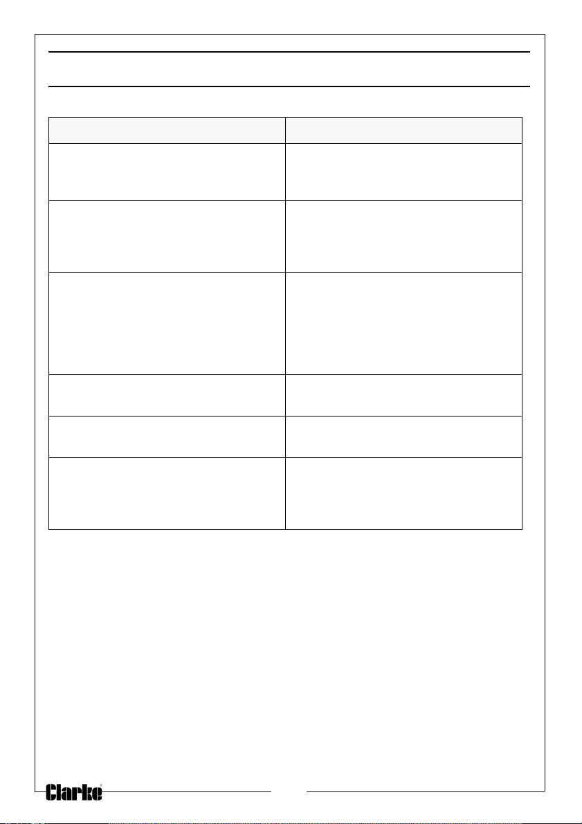
TROUBLESHOOTING
Problem & cause Remedy
No reception - Distance between
transmitters
No reception - High shielding
materials between the units (thick
walls, steel, concrete, isolating
aluminum foil etc.)
Interference from other sources (e.g.
wire
less radio, headset, speaker, etc.
operating on the same frequency).
No reception. Find a new location for the sensors
contrast LCD or no reception or
Poor
low batt
Temperature, humidity, or air
pressur
and receiver too great.
eries in sensors or receiver.
e is incorrect.
Reduce distance between
transmitter and receiver to receive
signal.
Find a different location for sensor
and/or receiver.
Find a different location for the
sensors and/or base station.
Neighbours using electrical devices
operation on the same signal
frequency can also cause
interference with reception.
and/or base station.
Change batteries ( check low
battery indicator on the LCD)
Check/replace batteries.
Adjust relative air pressure to a value
from a reliable source (TV radio,
etc.).
12
Page 13
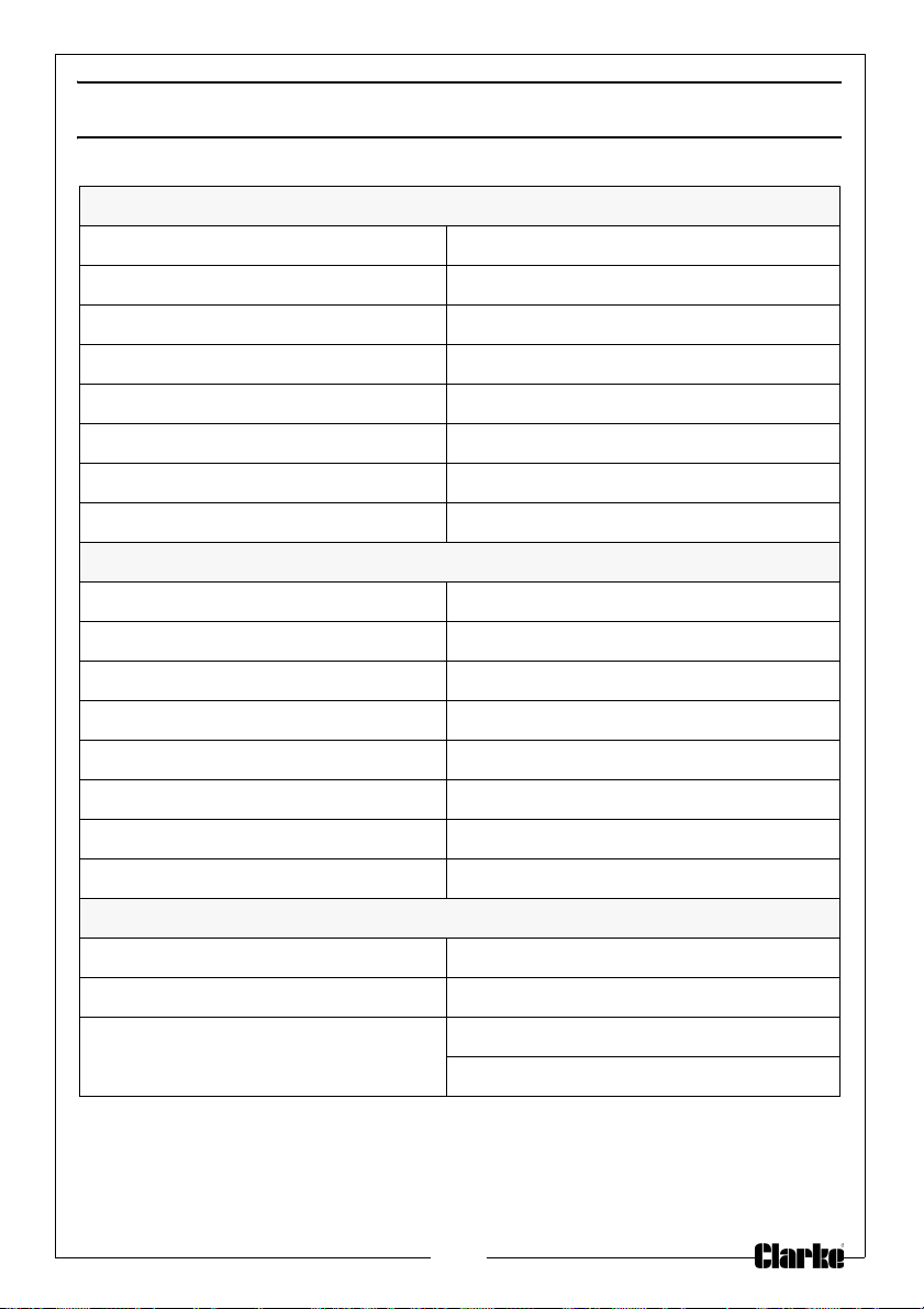
SPECIFICATIONS
Outdoor data
Transmission distance in open field : 100 metres maximum
Frequency 433MHz
Temp erature r an ge -40°C to + 65°C (show OF
Resolution 0.1 °C
Measuring range rel. humidity 20% - 95%
Humidity accuracy +/- 5% under 0 - 45°C
Measuring interval thermo-hygro sensor 48 sec
f outside range)
L i
Water proof level
Indoor data
Pressure / temperature 48 sec
Temp erature r an ge 0°C to + 60°C (show OFL i
Resolution 0.1°C
Measuring range rel. humidity 1%—99%
Resolution 1%
Measuring range air pressure 919 hPa - 1080 hPa
Resolution 0.1 hPa
Alarm duration
Power consumption
Base station 3XAA 1.5V LR6 Alkaline batteries
Remote sensor 2xAAA 1.5V LRO3 Alkaline batteries
Battery life Minimum 12 months for base station
IPX3
f
outside range)
120 sec
Minimum 24 months for remote sensor
13
Page 14
DECLARATION OF CONFORMITY
14
Page 15

15
Page 16

 Loading...