

Page 1
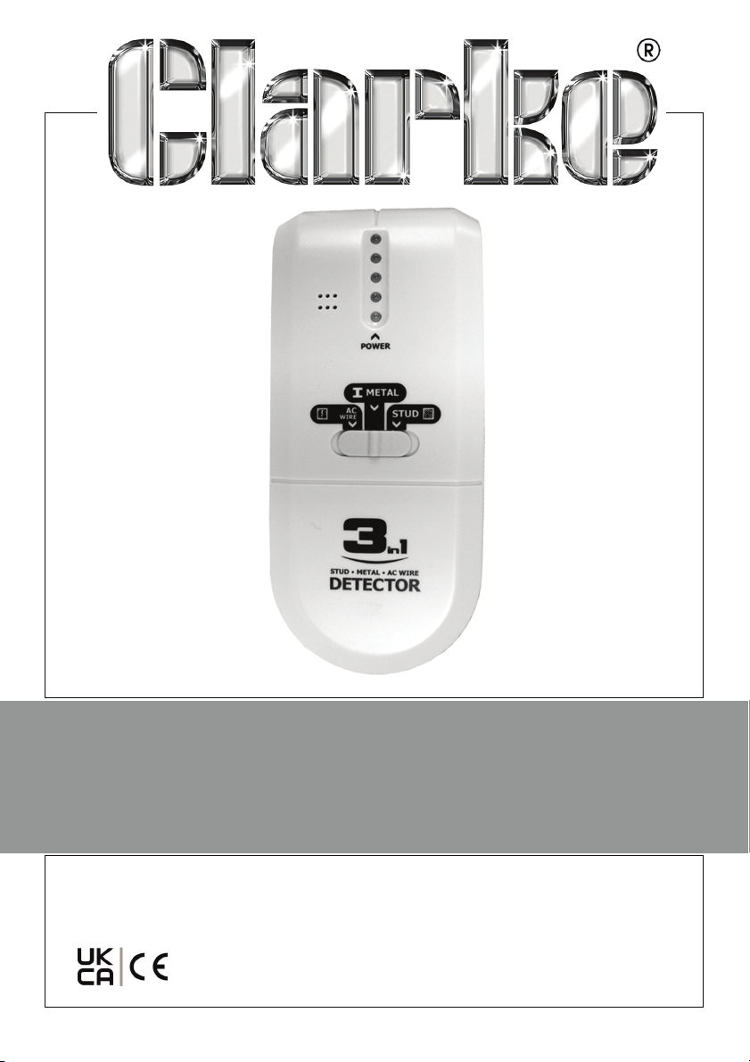
3 - 1 SUPER DETECTOR
MODEL NO: CDM65
PART NO: 45000135
OPERATING INSTRUCTIONS
ORIGINAL INSTRUCTIONS GC0321- Rev 2
Page 2

INTRODUCTION
Thank you for purchasing this CLARKE CDM65 Super
Detector. Before attempting to use this product, please
read these instructions carefully. In doing so you will ensure
your safety and you can look forward to your purchase
giving you long and satisfactory service.
The CLARKE 3 - 1 super detector is ideal for DIY and Trade
use.
GUARANTEE
This product is guaranteed against faulty manufacture for
a period of 12 months from the date of purchase. Please
keep your receipt which will be required as proof of
purchase.
This guarantee is invalid if the product is found to have
been abused or tampered with in any way, or not used for
its intended purpose. Faulty goods should be returned to
their place of purchase, no product can be returned to us
without prior permission.
This guarantee does not effect your statutory rights.
FEATURES
• Detects metal, studding and AC voltages
• Visual and audible warning
• Low power consumption
• Easy to use
2
Parts & Service: 020 8988 7400 / E-mail: [email protected] or [email protected]
Page 3
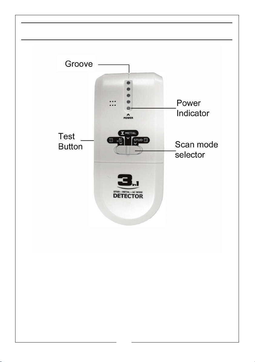
OVERVIEW
INSERTING THE BATTERY
1. Remove the battery door on the rear of the unit.
2. Connect a 9V PP3 battery to the battery clip.
3. Place the battery into the compartment.
4. Replace the battery door.
3
Parts & Service: 020 8988 7400 / E-mail: [email protected] or [email protected]
Page 4

AC VOLTAGE DETECTION
1. Set the selector switch to the AC WIRE position.
CALIBRATION
2. Hold the unit in the air away from any metal objects.
3. Press and hold the TEST button.
• The unit will beep twice when calibration is
complete. Do not release the TEST button.
USING THE UNIT
4. Keep holding the TEST button and place the unit on the
wall, slowly move the unit sideways across the wall.
• As you approach a live wire, the signal lights will
light up sequentially, the buzzer will sound when
you reach the edge of the live wire, when this
happens mark the point by placing a pencil mark
in the grove on top of the unit.
5. Carry on moving the unit in the same direction until all of
the signal LEDS go out and then reverse direction.
• Once again, mark the point at which the top LED
lights up and the buzzer sounds by placing a pencil
mark in the grove on top of the unit.
• The centre of the live wire is located mid way
between the two pencil marks.
4
Parts & Service: 020 8988 7400 / E-mail: [email protected] or [email protected]
Page 5

AC VOLTAGE DETECTION
Notes
• Some walls containing metal fibres (used in
fireproofing) will cause the detector to register a
voltage over a wider area.
• Rubbing or banging the wall may generate static
electricity, causing a false reading.
• Touching a damp wall being tested may also
cause a false positive reading.
• The unit will not detect wire inside metal shielding
or trunking.
5
Parts & Service: 020 8988 7400 / E-mail: [email protected] or [email protected]
Page 6

METAL DETECTION
1. Set the selector switch to the METAL position.
CALIBRATION
2. Hold the unit in the air away from any metal objects.
3. Press and hold the TEST button.
• The unit will beep twice when calibration is
complete. Do not release the TEST button.
USING THE DETECTOR
4. Keep holding the TEST button and place the unit on the
wall, slowly move the unit sideways across the wall.
• As you approach a metal object, the signal lights
will light up sequentially, the buzzer will sound when
you reach the edge of the metal object, when this
happens mark the point by placing a pencil mark
in the grove on top of the unit.
5. Carry on moving the unit in the same direction until all of
the signal LEDS go out and then reverse direction.
• Once again, mark the point at which the top LED
lights up and the buzzer sounds by placing a pencil
mark in the grove on top of the unit.
• The centre of the metal object is located mid way
between the two pencil marks.
• Wearing rings or other hand jewellery may cause a
false reading.
6
Parts & Service: 020 8988 7400 / E-mail: [email protected] or [email protected]
Page 7

STUD DETECTION
1. Set the selector switch to the STUD position.
CALIBRATION
2. Place the unit against the wall, press and hold the TEST
button.
• The unit will beep twice when calibration is
complete. Do not release the TEST button.
USING THE DETECTOR
3. Keep holding the TEST button and slowly move the unit
sideways across the wall.
• The buzzer will sound when you reach the edge of
the studding, when this happens mark the point by
placing a pencil mark in the grove on top of the
unit.
4. Carry on moving the unit in the same direction until all of
the signal LEDS go out and then reverse direction.
• Once again, mark the point at which the top LED
lights up and the buzzer sounds by placing a pencil
mark in the grove on top of the unit.
• The middle of the studding is located mid way
between the two pencil marks.
Always check that the “STUDDING” that you have detected
is not a metal pipe, see page 6.
7
Parts & Service: 020 8988 7400 / E-mail: [email protected] or [email protected]
Page 8

STUD DETECTION
NOTES
• You can use the detector on wallpaper, however it
may not be effective on some types of foil backed
wallpapers.
• If the unit is placed over studding during the
calibration, the unit will not work, simply recalibrate the unit 150 mm away from the last
place.
• The surface of the wall should be dry and flat.
• Always keep your free hand away from the wall
during detection.
• If you release the test button at any time during
detection, you will need to carry out the
calibration procedure again.
• Knots in wood can cause false readings to occur.
• Normally, studding is placed at intervals of 40 - 60
cm.
TIPS
• Re-calibrate the unit frequently to avoid
inaccurate readings.
• Take several readings vertically above, below, to
the left and right to confirm the reading.
8
Parts & Service: 020 8988 7400 / E-mail: [email protected] or [email protected]
Page 9
DETECTION DEPTHS
Iron Pipe (25mm) 30 mm
Studding (30 x 30mm)18 mm
AC Voltage (90-250V @ 50/60 Hz) 50 mm
Detection depth can vary due to moisture content and
texture of the wall, paint etc.
END OF LIFE
Do not dispose of this product with general
household waste. It must be disposed of
according to the laws governing Waste Electrical
and Electronic equipment, at a recognized
disposal facility.
SPECIFICATIONS
Battery: 9V, PP3 or equivalent
Weight: 164 g
Dimensions: (H x W x D) 151 x 65 x 31mm
Storage temperature: -20oC to 50oC
Operating temperature: -7oC to 40oC
9
Parts & Service: 020 8988 7400 / E-mail: [email protected] or [email protected]
Page 10
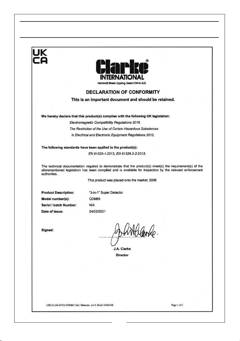
DECLARATION OF CONFORMITY - UKCA
10
Parts & Service: 020 8988 7400 / E-mail: [email protected] or [email protected]
Page 11
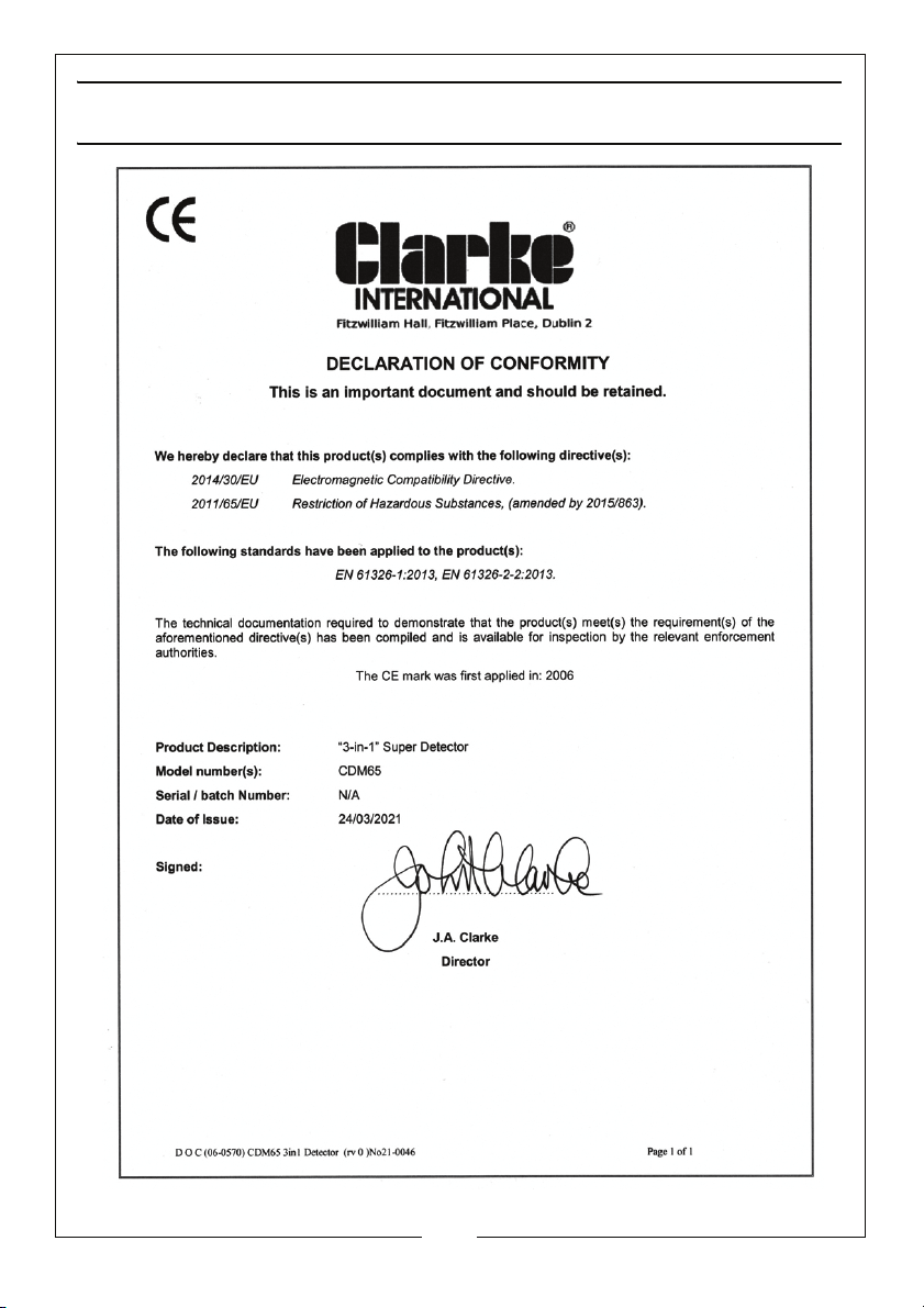
DECLARATION OF CONFORMITY - CE
11
Parts & Service: 020 8988 7400 / E-mail: [email protected] or [email protected]
Page 12

 Loading...