

Page 1
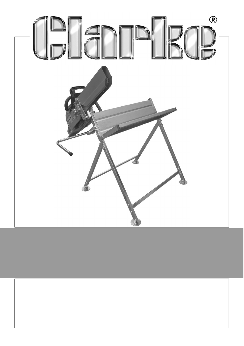
CHAINSAW LOG HORSE
MODEL NO: CCLH1
PART NO: 3402085
ASSEMBLY & USER
INSTRUCTIONS
GC0514
Page 2

INTRODUCTION
Thank you for purchasing this CLARKE Loghorse.
Before attempting to use this product, it is essential that you read this manual
thoroughly and carefully follow all instructions given. In doing so you will ensure
the safety of yourself and that of others around you, and you can also look
forward to the product giving you long and satisfactory service.
GUARANTEE
This CLARKE product is guaranteed against faulty manufacture for a period of
12 months from the date of purchase. Please keep your receipt as proof of
purchase.
This guarantee is invalid if the product is found to have been abused or
tampered with in any way, or not used for the purpose for which it was
intended.
Faulty goods should be returned to their place of purchase, no product can
be returned to us without prior permission. This guarantee does not effect your
statutory rights.
GENERAL SAFETY PRECAUTIONS
1. Always thoroughly familiarise yourself with this product & its operation, and
always read and understand the instructions and warnings in this manual
before using the equipment.
2. Ensure the log horse is located on firm level ground when in use.
3. Always locate the log horse in a position where it does not pose a hazard
to yourself or others in the vicinity when not in use.
4. Keep work area tidy and well lit. Cluttered or dark areas invite accidents.
5. Do not overreach. Keep proper footing and balance at all times. This
enables better control of the logs and saw in unexpected situations.
6. Keep children and bystanders away while operating a chain saw.
Distractions can cause you to lose control.
7. Use appropriate protective clothing as directed in the operating
instructions for the chainsaw, including safety gloves and eye protection.d.
2
Parts & Service: 020 8988 7400 / E-mail: [email protected] or [email protected]
Page 3
CONTENTS
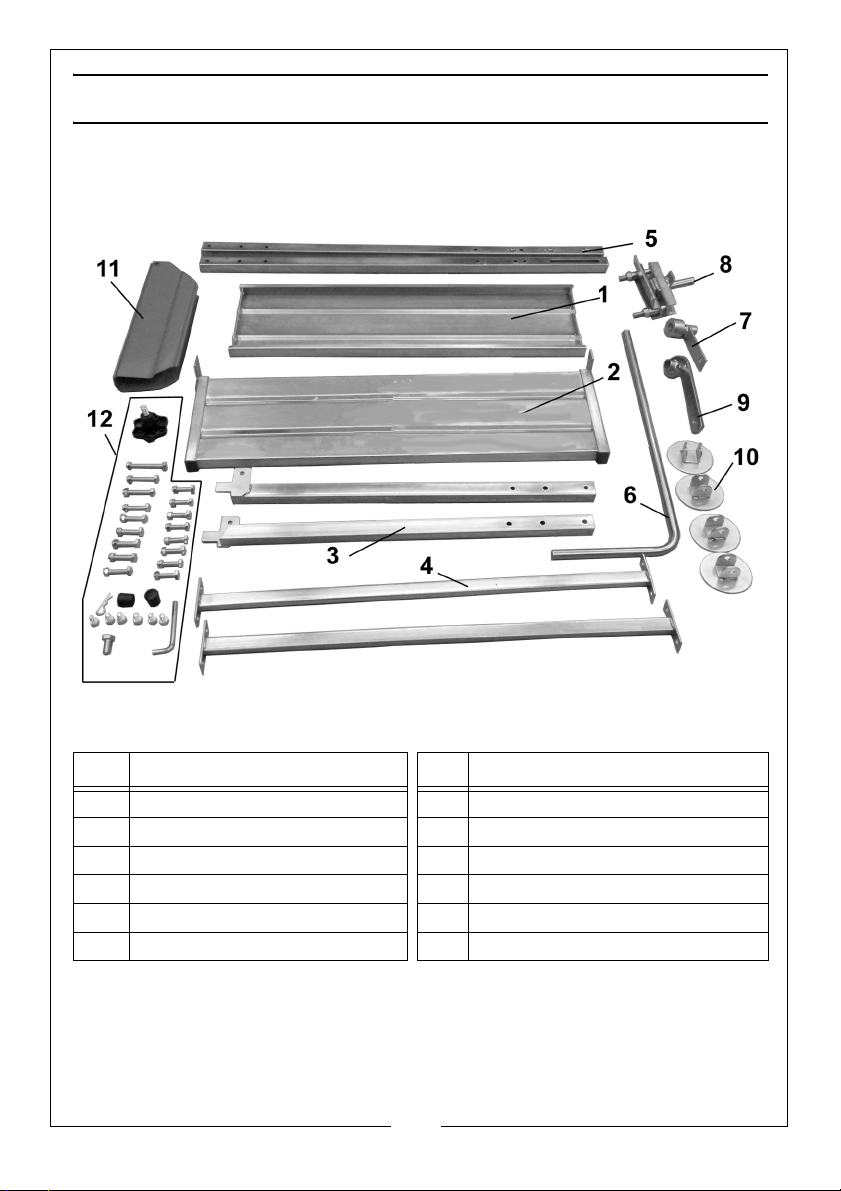
The CCLH1 Loghorse comprises the following components:
l
Item Description Item Description
1 Fixed Support Panel 7 Measuring Rod Mounting Bracket
2 Hinged Support Panel 8 Chainsaw Clamp
3 Short Leg 9 Clamp Mounting Bracket
4 Cross Member 10 Foot
5 Long Leg 11 Saw Guard
6 Measuring Rod (length stop) 12 Fixings Pack
3
Parts & Service: 020 8988 7400 / E-mail: [email protected] or [email protected]
Page 4
THE FIXINGS PACK
The fixings pack (12) includes the following:
1 x Hand-knob 2 x Plastic End Caps
1 x Large Securing Bolt 8 x 35mm Bolts/Nuts
1 x R-clip 6 x 40mm Bolts/Nuts
6 x Socket (Allen) Headed Bolts 2 x 50mm Bolts/Nuts
1 x Allen Key 1 x 65mm Bolt/Nut
When unpacking, check for damage or omissions etc. Any found should be
reported to your CLARKE dealer where the product was originally purchased.
Do not discard the packaging until the product is assembled.
ASSEMBLY
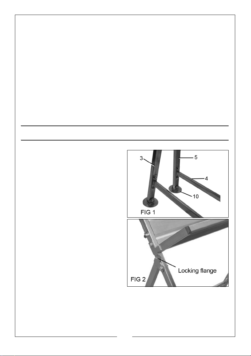
1. Join the two short legs (3)
together with one of the cross
member (4) using the 35 mm bolts
& nuts as in Fig 1.
2. Ensure that the locking flanges are
on the outside of the assembly as
in Fig 2.
• Repeat with the two long legs (5)
and the second cross-member.
3. Bolt the feet (10) to each of the
legs using 4 x 40 mm bolts & nuts
as shown in Fig 1.
4. Join the tops of the two leg
assemblies together using 2 x 40
mm bolts and nuts.
• The legs should hinge freely when
assembled.
4
Parts & Service: 020 8988 7400 / E-mail: [email protected] or [email protected]
Page 5
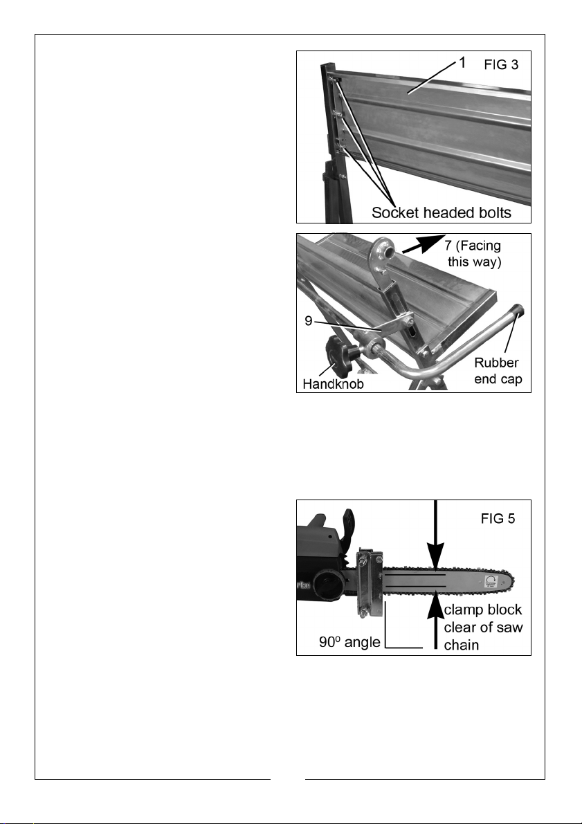
5. Secure the fixed support panel (1)
in place between the long legs
using 6 Allen headed bolts and
the socket wrench supplied as
shown in Fig 3.
6. Attach the hinged support panel
(2) to the long legs using the 2 x 50
mm bolts & nuts.
7. Insert the pivot clamp mounting
bracket (7) into the top of the
long leg as shown in Fig 4.
• Take note of the way it is facing in
the diagram.
8. Using the large securing bolt,
secure the measuring rod
mounting bracket (9) to the bolt
hole in the pivot clamp mounting
bracket as shown in Fig 4.
9. Slide the measuring rod (6), into the hole in the measuring rod mounting
bracket (9) and secure with the handknob as shown in Fig 4. Press the
rubber end caps into place at the ends of the rod.
NOTE: The measuring rod can be adjusted horizontally to allow each log
to be cut equally to the desired length.
10. Take your chainsaw and secure it
between the two solid blocks on
the inside faces of the chainsaw
clamp as shown in Fig 5.
• Make sure that the chainsaw is at
90 degrees to the assembly
before tightening the clamp bolts
to grip the chainsaw in place.
Take care that the clamp blocks
grip the chain bar centrally and
are clear of the moving chain.
5
Parts & Service: 020 8988 7400 / E-mail: [email protected] or [email protected]
Page 6
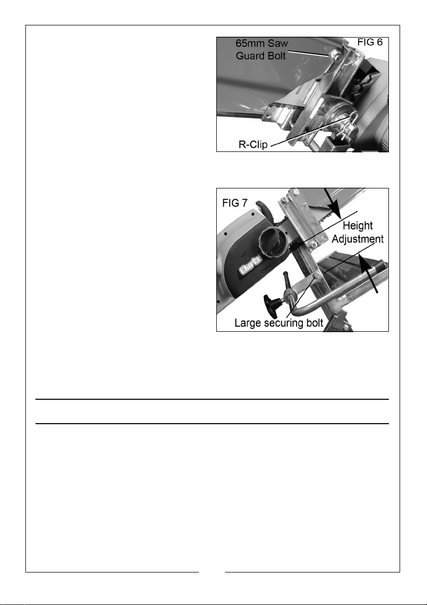
11. Attach the saw guard (11) to the
chainsaw clamp using the nut &
65mm bolt as shown in Fig 6. Do
not overtighten.
12. Once tightened, take the saw
and the clamp assembly together
and insert the pivot rod of the
clamp into the hole in the clamp
support. Secure in place with the
R-clip as shown in Fig 6.
13. Test the arc of travel to make sure that the chainsaw does not touch any
part of the log horse.
14. Adjust the height of the clamp
and measuring rod to suit the size
of the logs being cut as shown in
Fig 7.
NOTE: The chainsaw clamp support
can be adjusted vertically to
accommodate different
sized chain saws - the larger
and longer the saw, the
higher the pivot clamp
should be positioned.
15. Use the large securing bolt to
adjust the saw height, so that the
tip of your chainsaw ends just past the table and is able to cut completely
through the log.
The Log Horse is now ready for use.
SAFE OPERATION
The log horse should only be used on firm, level surfaces. It should not be used
for logs larger than those stated in the specification.
Chainsaws with a chain bar longer than 450 mm should not be used, since the
chain would protrude beyond the chain guard.
When using a chainsaw with the log horse it is essential that you follow all
safety guidelines in the instruction manual supplied with your chainsaw. You
should also follow any other appropriate health and safety regulations.
1. Ensure the nuts and bolts on the pivot clamp and guard are kept tight
before starting work.
6
Parts & Service: 020 8988 7400 / E-mail: [email protected] or [email protected]
Page 7
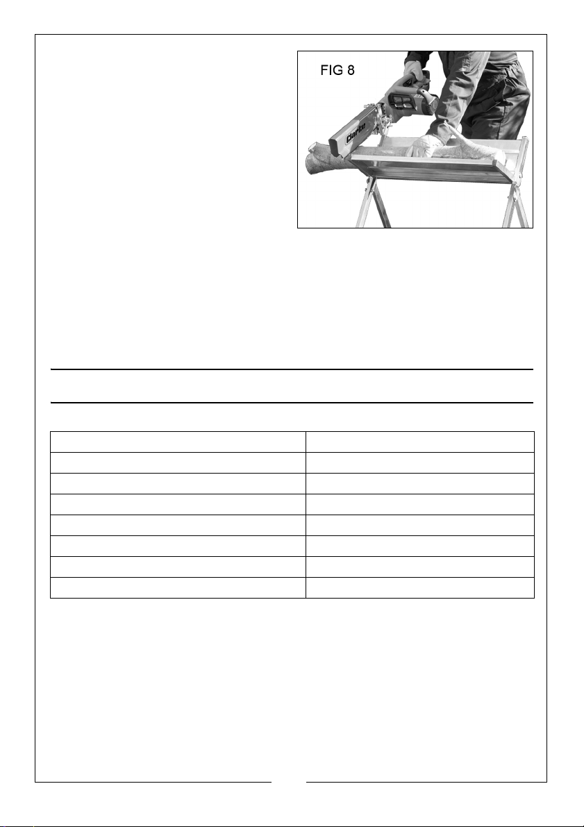
2. Place the log on the log horse
and butt the end of the log up
against the measuring rod.
3. Hold the log down firmly with your
left hand, keeping your hand well
away from the cutting chain at all
times as shown in Fig 8.
• Allow the chainsaw to do the
work, do not force the chainsaw
through the log.
4. Detach the pivot clamp and
guard by removing the R-clip when using the log horse separately from the
chainsaw.
5. All moving / adjustable parts should be kept sufficiently lubricated to resist
corrosion. Store in a dry place not exposed to the weather.
6. When operating an electric chainsaw always use a residual current device
(RCD) to ensure it will cut out in the event of difficulties arising.
SPECIFICATIONS
Feature Specification
Maximum Chain Bar length 450mm
Maximum Log Length 1800mm
Maximum Log Diameter 200mm
Maximum Log Weight 120kg
Product Weight 11.1kg
Product Dimensions (W x D x H) 1310 x 715 x 785mm
Product Footprint (L x W) 715 x 815mm
Please note that the details and specifications contained herein, are correct at the time
of going to print. However, CLARKE International reserve the right to change
specifications at any time without prior notice.
ENVIRONMENTAL PROTECTION
Recycle unwanted materials instead of disposing of them as waste. All unwanted accessories & packaging should be sorted and taken to a recycling
centre for disposal in a manner which is compatible with the environment.
7
Parts & Service: 020 8988 7400 / E-mail: [email protected] or [email protected]
Page 8

 Loading...