

Page 1

WARNING: Read these instructions before using the machine
CHAINSAW SHARPENER
MODEL NO: ECSS2
PART NO: 3402077
OPERATION & MAINTENANCE
INSTRUCTIONS
ORIGINAL INSTRUCTIONS GC1020 -REV 1
Page 2
INTRODUCTION
Thank you for purchasing this Chainsaw Sharpener.
Please read this manual thoroughly, before attempting to operate, and
carefully follow all instructions given.
It is vitally important that ALL precautions are taken, as specified, which will not
only provide protection for yourself and that of others around you, but will also
ensure that the product will give you long and satisfactory service.
GUARANTEE
This CLARKE product is guaranteed against faulty manufacture for a period of
12 months from the date of purchase. Please keep your receipt as proof of
purchase.
This guarantee is invalid if the product is found to have been abused or
tampered with in any way, or not used for the purpose for which it was
intended.
Faulty goods should be returned to their place of purchase, no product can
be returned to us without prior permission.
This guarantee does not affect your statutory rights.
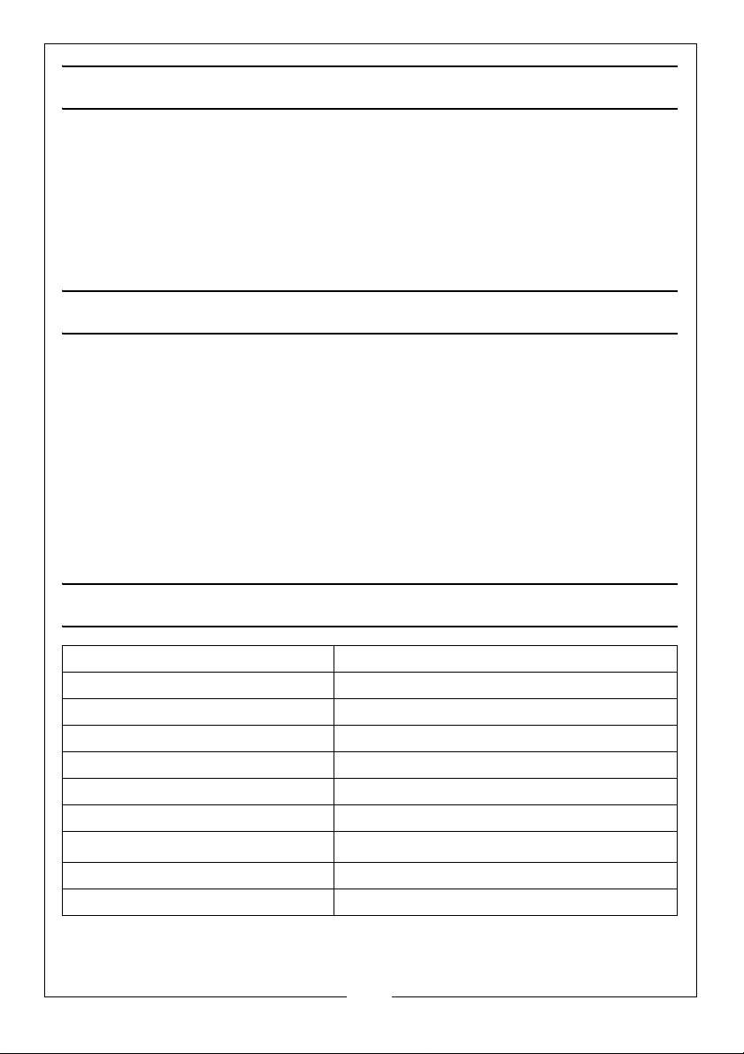
SPECIFICATIONS
Operating Voltage: 230 V @ 50Hz
Nominal Power 85 Watts
No Load Speed 4800 rpm
Disc Diameter 108 mm
Protection Class II
Sound Pressure Level LpA 77 dB
Sound Power Level LWA 90 dB
Vibration
Dimensions (L x W x H) 200 x 230 x 315 mm
Weight (kg) 2.9 kg
Parts & Service: 020 8988 7400 / E-mail: [email protected] or [email protected]
2.69 m/s
2
2
Page 3
SAFETY PRECAUTIONS
WARNING: READ ALL INSTRUCTIONS. FAILURE TO FOLLOW ALL
INSTRUCTIONS LISTED BELOW MAY RESULT IN ELECTRIC SHOCK, FIRE AND/
OR SERIOUS INJURY. THE TERM “POWER TOOL” IN ALL WARNINGS LISTED
BELOW REFERS TO YOUR CHAINSAW SHARPENER.
WORK AREA
1. Keep work area clean and well lit. Cluttered and dark areas invite
accidents.
2. Do not operate power tools in explosive atmospheres, such as in the
presence of flammable liquids, gases or dust. Power tools create sparks
which may ignite the dust or fumes.
3. Keep children and bystanders away while operating a power tool.
Distractions can cause you to lose control.
ELECTRICAL SAFETY
1. Avoid body contact with earthed or grounded surfaces such as pipes,
radiators, ranges or refrigerators. There is an increased risk of electric shock
if your body is earthed or grounded.
2. Do not expose power tools to rain or wet conditions. Water entering a
power tool will increase the risk of electric shock.
3. When operating a power tool outdoors, use an extension cord suitable for
outdoor use. Use of a cord suitable for outdoor use reduces the risk of
electric shock.
PERSONAL SAFETY
1. Stay alert, watch what you are doing and use common sense when
operating a power tool. Do not use a power tool while you are tired or
under the influence of drugs, alcohol or medication. A moment of
inattention while operating power tools may result in personal injury.
2. Use safety equipment. Always wear eye protection. Safety equipment such
as dust mask, non-skid safety shoes, or hearing protection used for
appropriate conditions will reduce personal injuries.
3. Avoid accidental starting. Ensure the switch is in the off position before
connecting to the power supply.
4. Do not overreach. Keep proper footing and balance at all times. This
enables better control of the power tool in unexpected situations.
3
Parts & Service: 020 8988 7400 / E-mail: [email protected] or [email protected]
Page 4

5. Dress properly. Do not wear loose clothing or jewellery. Keep your hair,
clothing and gloves away from moving parts. Loose clothes, jewellery or
long hair can be caught in moving parts.
POWER TOOL USE AND CARE
1. Do not force the power tool. Use the correct power tool for your
application. The correct power tool will do the job better and safer at the
rate which it was designed.
2. Do not use the power tool if the switch does not turn it on and off. Any
power tool that cannot be controlled with the switch is dangerous and
must be repaired.
3. Disconnect the battery before making any adjustments, changing
accessories, or storing power tools. Such preventive safety measures
reduce the risk of starting the power tool accidentally.
4. Store idle tools out of the reach of children and do not allow persons
unfamiliar with the power tool or these instructions to operate the power
tool. Power tools are dangerous in the hands of untrained users.
5. Maintain power tools. Check for misalignment or binding of moving parts,
breakage of parts and any other condition that may affect the power tools
operation. If damaged, have the power tool repaired before use. Many
accidents are caused by poorly maintained power tools.
6. Keep cutting tools sharp and clean. Poorly maintained cutting tools with
sharp cutting edges are less likely to bind and are easier to control.
7. Use the power tool and accessories in accordance with these instructions
and in the manner intended for the particular type of power tool, taking
into account the working conditions and the work to be performed. Use of
the power tool for operations different from intended could result in a
hazardous situation.
SERVICING
1. Have your power tool serviced by a qualified repair person using only
identical replacement parts. This will ensure that the safety of the power
tool is maintained.
4
Parts & Service: 020 8988 7400 / E-mail: [email protected] or [email protected]
Page 5
ADDITIONAL SAFETY INSTRUCTIONS FOR CHAINSAW SHARPENERS
1. Remember that the wheel continues to rotate after the tool is switched off
2. The sharpener is designed for sharpening all common chainsaw chains. Do
not use it for any other purpose.
3. Do not sharpen damaged chainsaw chains.
4. Do not operate the sharpener without the protective cover in place and
make sure that all parts are firmly assembled before starting the sharpener.
5. Do not operate the sharpener if it does not work correctly or has been
dropped.
6. Do not disassemble the sharpener and do not try to repair it yourself.
Contact your Clarke customer service.
ENVIRONMENTAL PROTECTION
Recycle unwanted materials instead of disposing of them as waste.
All tools, accessories and packaging should be sorted, taken to a
recycling centre and disposed of in a manner which is compatible
with the environment.
5
Parts & Service: 020 8988 7400 / E-mail: [email protected] or [email protected]
Page 6
ELECTRICAL CONNECTIONS
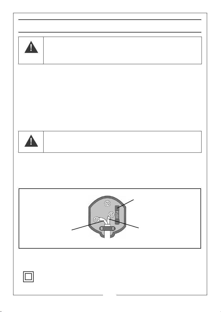
Plug must be BS1363/A approved.
Always fit a 5 Amp fuse.
Ensure that the outer sheath of the cable is firmly held by the clamp
Neutral
(Blue)
Live
(Brown)
WARNING: READ THESE ELECTRICAL SAFETY INSTRUCTIONS
THOROUGHLY BEFORE CONNECTING THE PRODUCT TO THE MAINS
SUPPLY.
Before switching the product on, make sure that the voltage of your electricity supply is
the same as that indicated on the rating plate. This product is designed to operate on
230V AC 50Hz. Connecting it to any other power source may cause damage.
This product may be fitted with a non-rewireable plug. If it is necessary to change the
fuse in the plug, the fuse cover must be refitted. If the fuse cover becomes lost or
damaged, the plug must not be used until a suitable replacement is obtained.
If the plug has to be changed because it is not suitable for your socket, or due to
damage, it should be cut off and a replacement fitted, following the wiring instructions
shown below. The old plug must be disposed of safely, as insertion into a mains socket
could cause an electrical hazard.
WARNING: THE WIRES IN THE POWER CABLE OF THIS PRODUCT ARE
COLOURED IN ACCORDANCE WITH THE FOLLOWING CODE:
BLUE = NEUTRAL BROWN = LIVE
If the colours of the wires in the power cable of this product do not correspond with the
markings on the terminals of your plug, proceed as follows.
•The Blue wire must be connected to the terminal marked N or coloured Black.
•The Brown wire must be connected to the terminal marked L or coloured Red.
We strongly recommend that this machine is connected to the mains supply via a
Residual Current Device (RCD)
If in any doubt, consult a qualified electrician. DO NOT attempt any repairs yourself.
Parts & Service: 020 8988 7400 / E-mail: [email protected] or [email protected]
This symbol indicates that this is a Class II product, and does not require an earth
connection.
6
Page 7
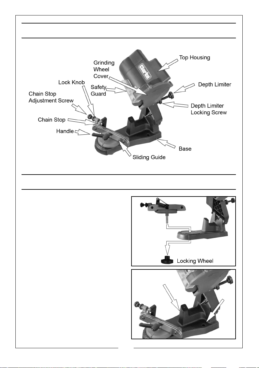
OVERVIEW
ASSEMBLY
Insert the chain holder assembly into
the base as shown and secure from
below using the Locking Wheel
supplied.
• Make sure the pointer is
positioned pointing forwards
(away from the grinding wheel).
MOUNTING THE SHARPENER
1. Place the base on a solid, level
surface, e.g. a workbench.
2. Mount the chainsaw sharpener
using the mounting holes on the
base (bolts not supplied).
• The sharpener must overhang
the workbench to allow access
to the locking wheel.
7
Parts & Service: 020 8988 7400 / E-mail: [email protected] or [email protected]
Page 8
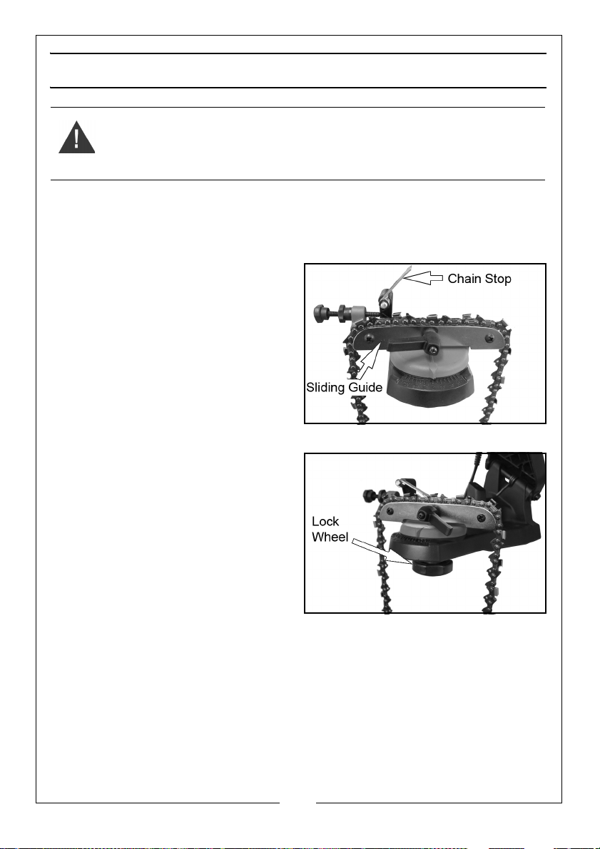
BEFORE USE / SETUP
WARNING: MAKE SURE THE SHARPENER IS NOT CONNECTED TO THE
MAINS POWER SUPPLY DURING SETUP.
1. Clean the chain before sharpening. Wash it with a non-flammable solvent.
Do not use petrol. Dry the chain.
FITTING THE CHAIN
2. Lift up the chain stop and place
the chain in the sliding guide as
shown.
• Look at each tooth on the
chain and start with the most
worn tooth. Position this tooth
roughly in the centre of the
sliding guides. All other teeth will
be ground to the same depth.
ADJUST THE SHARPENING ANGLE
1. Loosen the locking wheel to allow
the chain holder assembly to turn.
2. Check with your chain
manufacturer to determine the
angle you need.
3. Rotate the chain holder assembly
to the angle required.
4. Tighten the locking wheel.
• Do not rotate the chain holder
assembly when the grinding disc is moving.
8
Parts & Service: 020 8988 7400 / E-mail: [email protected] or [email protected]
Page 9
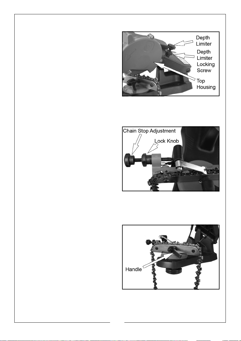
LIMITING THE DEPTH OF CUT
1. Lower the top housing so that the
grinding wheel skims the chain
tooth.
2. Hold it at that position while you
tighten the depth limiter until it
touches the stop on the base.
• The grinding wheel will only go
down to that point from now
on.
3. Tighten the depth limiter locking
screw against the main body to secure.
LIMIT THE AMOUNT OF MATERIAL REMOVED
1. Depending on the amount of
material you wish to remove,
tighten or loosen the Lock Knob
and adjust the chain stop
adjustment screw.
• This will determine how much
material is removed. Once you
set the chain stop adjustment
screw, fully tighten the lock
knob.
2. Lower the chain stop so that it drops behind the tooth that you want to
start with.
FINALLY
1. Lock the chain in the sliding guide
by turning the handle clockwise.
The handle should be positioned
so that you can easily release and
tighten it.
• You will need to release it each
time you move to the next
tooth, and tighten it to sharpen
each tooth.
9
Parts & Service: 020 8988 7400 / E-mail: [email protected] or [email protected]
Page 10
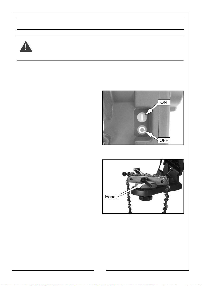
SHARPENING A CHAIN
WARNING: WHEN SHARPENING, ALWAYS WEAR SAFETY GOGGLES.
NOTE: Sharpen all the teeth on one side first (every other tooth) before
adjusting the angle to complete the job.
1. Put on your protective goggles and make sure the immediate area is clear
of bystanders.
2. Plug in the power cable and push
the (I) button to turn on the
sharpener.
3. Slowly lower the grinding wheel to
sharpen the tooth.
• If you notice slight errors in your
settings, turn off the sharpener
and unplug it before you make
your adjustments.
4. After sharpening the tooth, release
the top housing and turn off the sharpener.
5. Rotate the handle anti-clockwise,
and move the chain so that the
next tooth on that side of the
chain (every other tooth) is
positioned against the chain stop.
6. Re-tighten the handle to lock the
chain in place.
7. Turn the sharpener back on and
repeat this process until you have
sharpened all of the teeth on this
side (every other tooth) of the chain.
8. Loosen the locking wheel and rotate the chain holder assembly to the
same angle on the other side of the 0 on the scale then retighten the
locking wheel.
9. Place the first tooth that hasn't been sharpened in position against the
chain stop.
10. Repeat the sharpening procedure for the remaining teeth on the chain.
10
Parts & Service: 020 8988 7400 / E-mail: [email protected] or [email protected]
Page 11
OPERATING HINTS
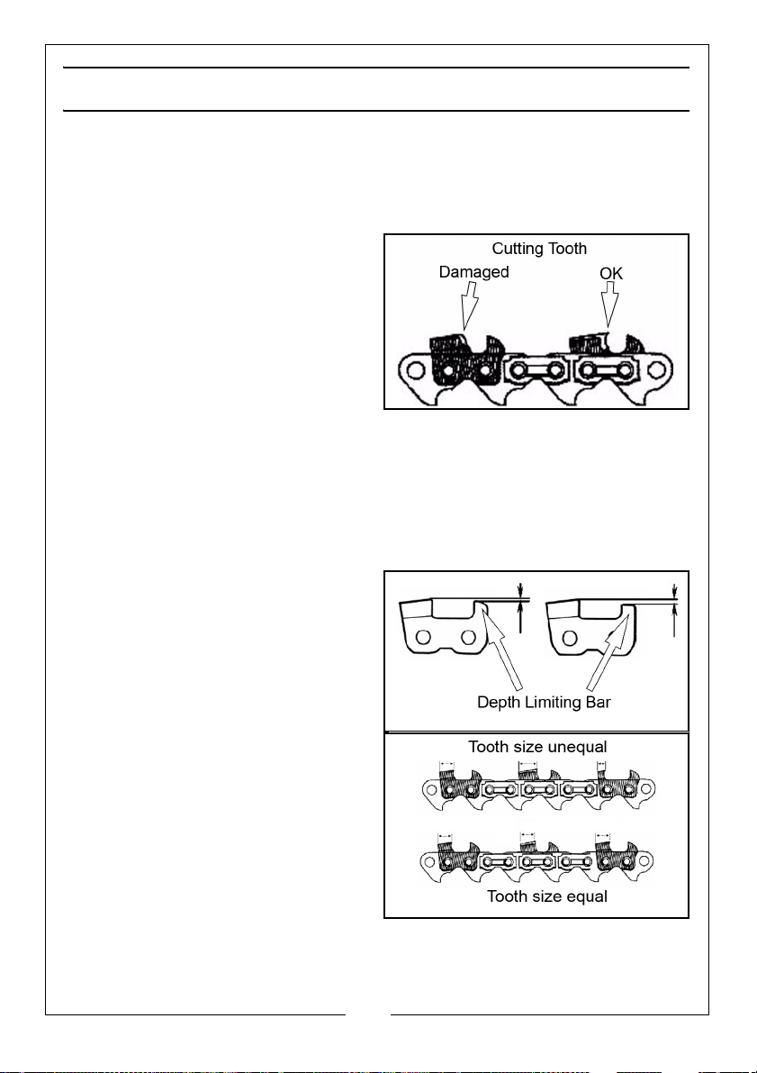
• Before you sharpen the chainsaw chain check it for damage, such as:-
bent or abraded chain links.- broken cutting teeth, loose rivets or broken
rivet heads.
If any damage is found, replace the entire chain.
• A sharp chainsaw produces
wood chips and pulls itself into
the timber being cut. When it
becomes blunt, sawdust will
start being produced during
cutting operations.
• You should sharpen the chain if
you notice that you have to use
force to cut through the timber,
i.e. if the saw does not “pull” anymore.
• Sharpen all cutting teeth as uniformly as possible. This will ensure smooth
operation with a minimum of vibration.
• Blunt cutting teeth or parts damaged by stones may cause an inclined
cut during chain saw operation, and may also increase the wear on the
running face of the cutting teeth.
• The depth limiter bars must be
profiled by hand. Ensure that all
depth limiter bars are equal in
height.
• Ensure that all cutting teeth are
sharpened to the same cutting
angle.
• During sharpening occasionally
check that the cutting-angle is
set correctly, as this setting may
go out of adjustment due to
vibration.
• Make sure that all teeth are
sharpened as evenly as
possible. Only sharpen the
teeth, never sharpen the chain
links.
• Sharpening teeth to unequal lengths can cause a side drift when
sawing.
11
Parts & Service: 020 8988 7400 / E-mail: [email protected] or [email protected]
Page 12
CLEANING AND MAINTENANCE
WARNING: BEFORE STARTING ANY CLEANING OR MAINTENANCE
PROCEDURES, DISCONNECT THE PLUG FROM MAINS SUPPLY.
CHANGING THE GRINDING DISC
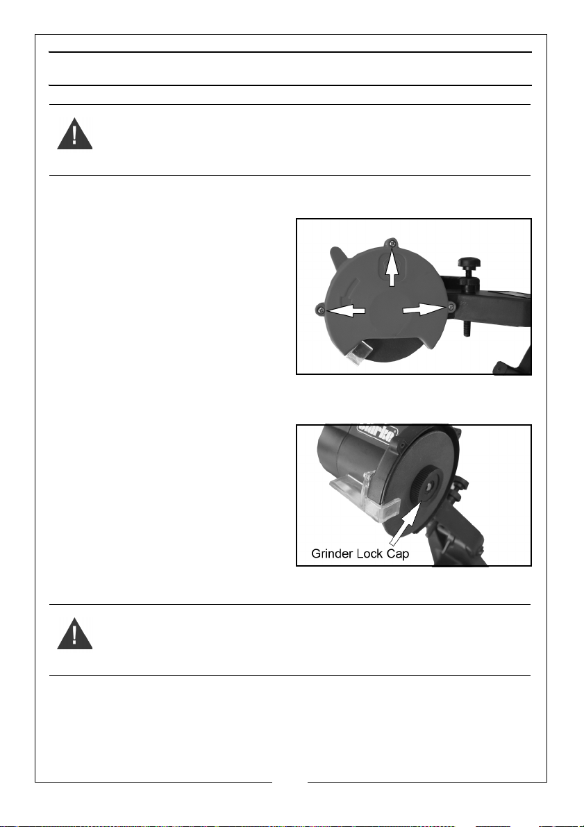
1. Remove the three screws holding
the Grinding Wheel Cover. Set the
cover aside.
2. Unscrew the Grinder Lock Cap
that holds the Grinding Wheel in
place.
3. Install the new wheel on the
Grinding Wheel Base, making sure
it fits properly.
4. Replace the Grinder Lock Cap.
5. Replace the Grinding Wheel Cover.
• Only use grinding discs with a
diameter of 108 mm.
• Replacement grinding disc
speed must meet or exceed the
RPM rating of the sharpener.
• Replacement discs are
available from your Clarke
dealer part number (3402079)
NOTE: Do not use a grinding wheel if
it is chipped, cracked, or worn.
WARNING: NEVER OPERATE THE SHARPENER WITHOUT THE GRINDING
WHEEL COVER IN PLACE.
12
Parts & Service: 020 8988 7400 / E-mail: [email protected] or [email protected]
Page 13
Page 14
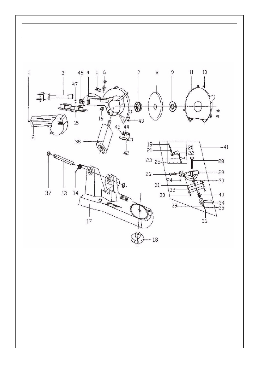
PARTS LIST
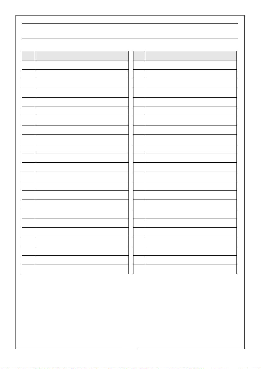
No Description No Description
1 Screw 25 Retaining Ring
2 Motor Cover 26 Lower Knob
3 Power Cable 27 Screw
4 Top Housing 28 Bolt
5 Switch Plate 29 Chain Saw Frame
6 Lock Stop 30 Square Neck Screw
7 Grinding wheel base 31 Sliding Guide
8 Grinding Wheel 32 Pad
9 Grinder Lock Cap 33 Screw
10 Screw 34 Handle
11 Grinding Wheel Cover 35 Spring
13 Punching Axis 36 Lock Screw
14 Torsion Spring 37 Retaining Ring
15 Switch Circuit Board 38 Motor
16 Nut 39 Washer
17 Base 40 Nut
18 Lock Wheel 42 Safe Guard
19 Screw 43 Screw
20 Washer 44 Spring Washer
21 Bearing 45 Nut
22 Swing Arm 46 Pressure Panel
23 Chain Stop 47 Screw
24 Tension Spring
14
Parts & Service: 020 8988 7400 / E-mail: [email protected] or [email protected]
Page 15
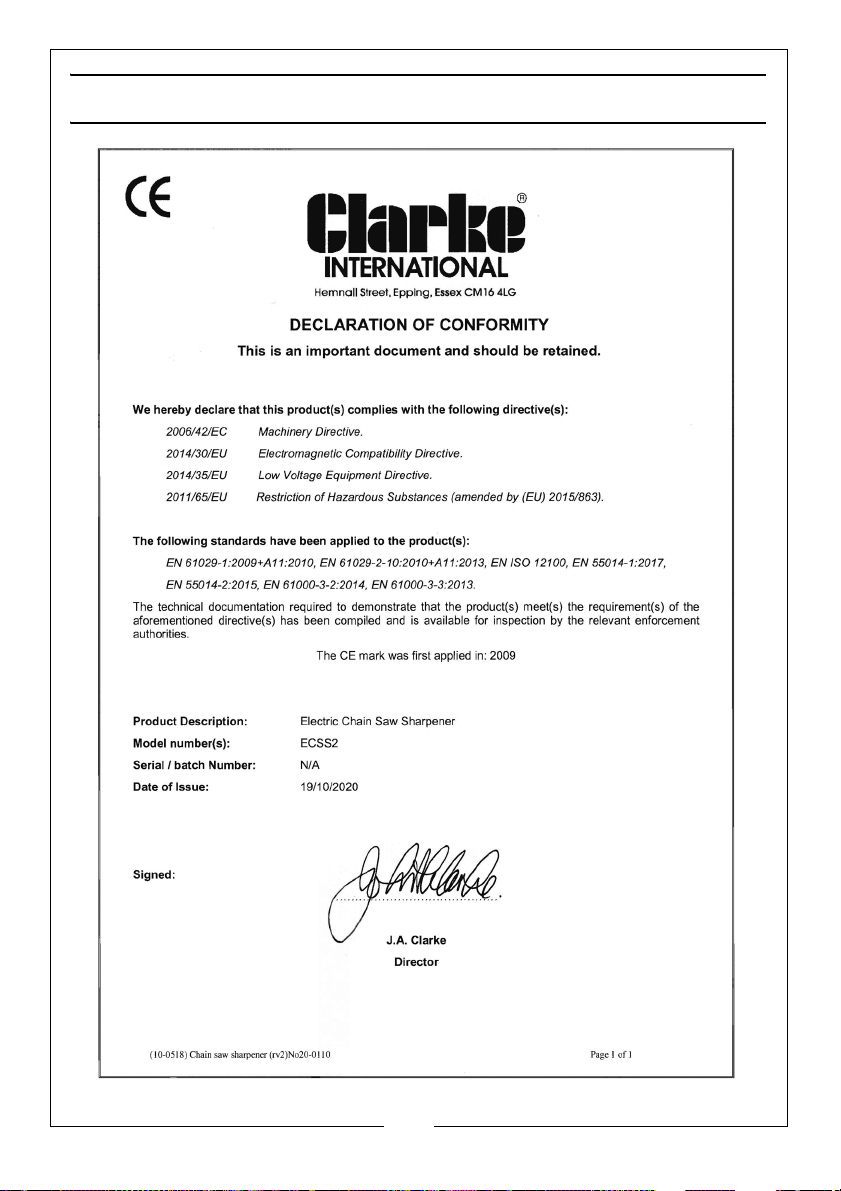
DECLARATION OF CONFORMITY
15
Parts & Service: 020 8988 7400 / E-mail: [email protected] or [email protected]
Page 16

 Loading...