

Page 1
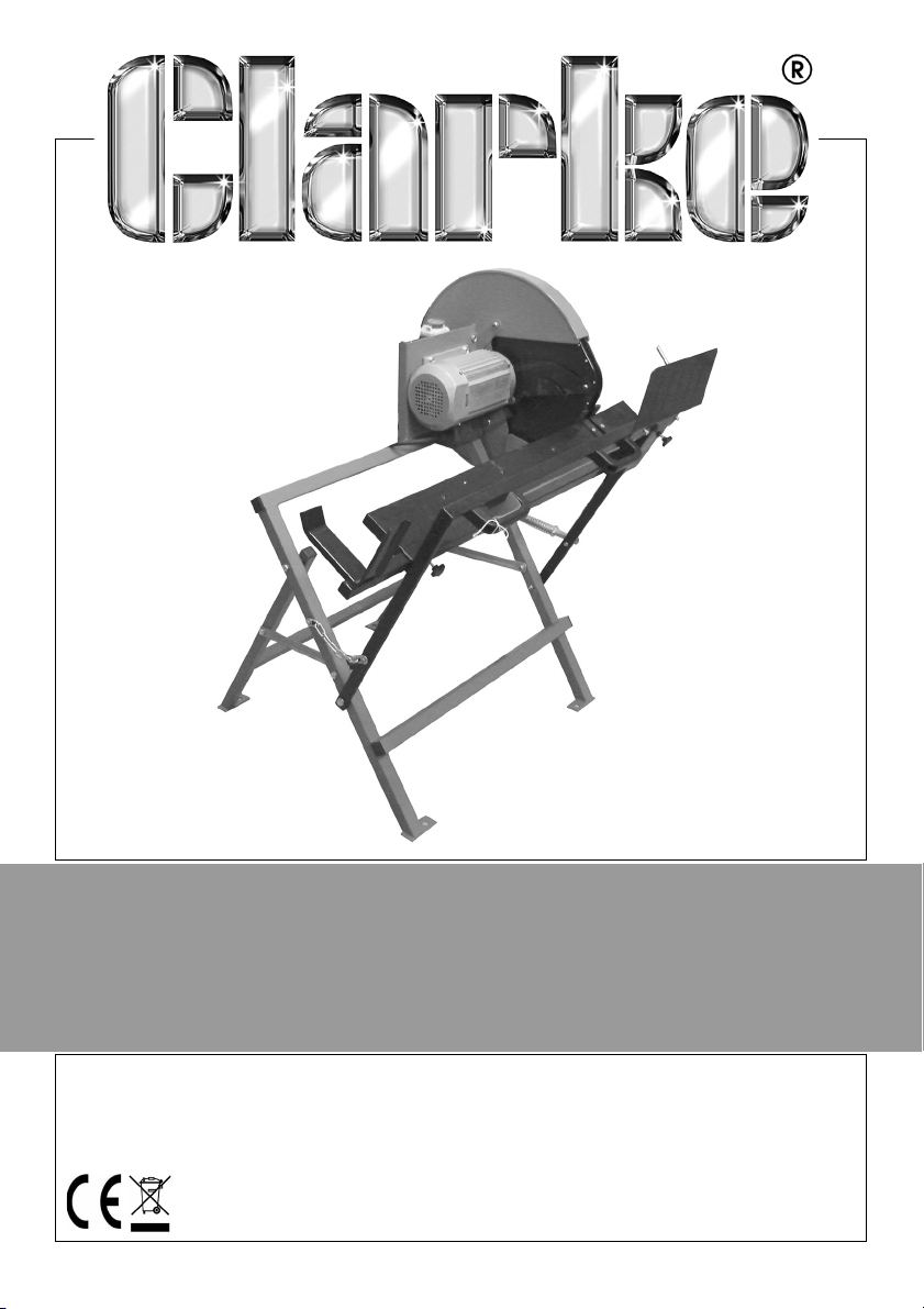
400MM LOGSAW
MODEL NO: CLS400
PART NO: 3401995
ASSEMBLY &
OPERATING INSTRUCTIONS
GC0216
Page 2
INTRODUCTION
Thank you for purchasing this CLARKE Log Saw.
The CLARKE CLS400 is a single speed circular saw directly driven by the motor.
It is equipped with a log cradle which holds the log steady while working and
has a hinged guard which retracts as the log is pushed against the saw.
Before attempting to use this product, please read this manual thoroughly and
follow the instructions carefully. In doing so you will ensure the safety of yourself
and that of others around you, and you can look forward to your purchase
giving you long and satisfactory service.
GUARANTEE
This product is guaranteed against faulty manufacture for a period of 12
months from the date of purchase. Please keep your receipt which will be
required as proof of purchase.
This guarantee is invalid if the product is found to have been abused or
tampered with in any way, or not used for the purpose for which it was
intended.
Faulty goods should be returned to their place of purchase, no product can
be returned to us without prior permission.
This guarantee does not effect your statutory rights.
ENVIRONMENTAL RECYCLING POLICY
Through purchase of this product, the customer is taking on the
obligation to deal with the WEEE in accordance with the WEEE
regulations in relation to the treatment, recycling & recovery and
environmentally sound disposal of the WEEE.
In effect, this means that this product must not be disposed of with general
household waste. It must be disposed of according to the laws governing
Waste Electrical and Electronic Equipment (WEEE) at a recognised disposal
facility.
If disposing of this product or any damaged components, do not dispose of
with general waste. This product contains valuable raw materials. Metal
products should be taken to your local civic amenity site for recycling of metal
products.
2
Parts & Service: 020 8988 7400 / E-mail: [email protected] or [email protected]
Page 3
SPECIFICATIONS
Model Number CLS400
Product Dimensions: (L x W x H) 961 x 885 x 1020 mm
Weight 36.5 kg
Max Cutting Length 1500 mm
Cutting Capacity (min/max dia) 30-135 mm
Operating Voltage 230V / 50Hz
Fuse Rating 13A
Motor Power 2000 W
Product Insulation Class I
IP Rating IP54
No load blade Speed 2800 rpm
Duty Cycle S6 (40%)
Blade Diameter 405 mm
Internal Bore Dia 30 mm
Teeth Thickness 3.2 mm
No of Saw Teeth 32
Sound Pressure Level 98 dB LpA
Sound Power Level 108 dB LWA
Guaranteed Sound Power Level 104 dB LWA
SAFETY WARNINGS
WORK AREA
1. Keep the work area clean and well lit. Cluttered and dark areas invite
accidents.
2. Do not operate power tools in explosive atmospheres such as in the
presence of flammable liquids, gasses or dust. Power tools create sparks
which may ignite dust or fumes.
3. Keep children and bystanders away while operating any power tool.
Distractions can cause you to lose control.
3
Parts & Service: 020 8988 7400 / E-mail: [email protected] or [email protected]
Page 4

ELECTRICAL SAFETY
1. Power tools must match the power outlet. Never modify the plug in any
way. Do not use adaptor plugs with earthed (grounded) power tools.
Correct plugs and outlets will reduce the risk of electric shock.
2. Do not expose power tools to rain or wet conditions. Any water entering
power tools will increase the risk of electric shock.
3. Do not abuse the electrical cable. Never use the cable for pulling or
unplugging the power tool. Keep the cable away from sources of heat, oil,
sharp edges or moving parts. Damaged or tangled cables increase the risk
of electric shock.
4. Use outdoor extension leads. If working outdoors, always use an approved
cable extension suitable for the power rating of this tool (see
specifications), the conductor size should also be at least the same size as
that on the machine, or larger.
5. When using a cable reel, always unwind the cable completely. We strongly
recommend that this machine is connected to the mains supply via a
Residual Current Device (RCD).
PERSONAL SAFETY
1. Stay alert, watch what you are doing and use common sense when you
are operating a power tool. Do not operate a power tool when you are
tired, ill or under the influence of alcohol, drugs or medication. A moment
of inattention may result in personal injury.
2. Wear personal protective equipment including eye protection. Safety
equipment such as a dust mask, non-skid shoes or hearing protection used
for appropriate conditions will reduce personal injuries. Use a face or dust
mask if operation is particularly dusty. Wear ear protectors/defenders as
the noise level of this machine can exceed 85dB (A).
3. Do not over-reach. Keep your proper footing and balance at all times. This
enables better control of the power tool in unexpected situations.
4. Concentrate on the job in hand, no matter how trivial it may seem. Be
aware that accidents are caused by carelessness due to familiarity.
5. Avoid accidental starting of the machine. Ensure the switch is in the off
position before plugging the machine in to the power supply. Plugging in
power tools that are switched on invites accidents.
6. Dress properly. Do not wear loose clothing or jewelry which may get
caught in moving parts. Wear protective hair covering to contain long hair.
For best footing, wear rubber soled footwear. Keep floor clear of oil, scrap
wood, etc.
4
Parts & Service: 020 8988 7400 / E-mail: [email protected] or [email protected]
Page 5

7. Wear gloves while handling saw blades and always store them in the
protective packing provided. A dust mask should be warn to reduce the
inhalation of harmful dust.
8. Always remove and stack cut timber in a suitable place, away from the
operator.
9. Switch the machine OFF immediately after the task is completed.
POWER TOOL USE AND CARE
1. Do not force the machine. Use the correct tool for your application. It will
do a better and safer job at the rate for which it was designed.
2. Do not use the power tool if the switch does not turn it on and off. Any
power tool that cannot be controlled with the switch is dangerous and
must be repaired.
3. Disconnect the power tool from the power supply before making any
adjustments or storing the tool. These measures will reduce the risk of the
power tool starting accidentally.
4. Store power tools out of the reach of children and do not allow persons
unfamiliar with these instructions to operate this product. Power tools are
potentially dangerous in the hands of untrained users.
5. Maintain power tools in top condition. Keep machines clean for the best
and safest performance. Check for misalignment or binding of moving
parts, broken parts, or any condition that may affect the machine’s
operation. If damaged, have the machine repaired before use. Many
accidents are caused by poorly maintained power tools.
6. Machine cleanliness. Do not allow the ventilation slots in the motor to
become blocked with dust.
7. Check the power tool for damage before use. Any damaged part should
be inspected to ensure that it will operate properly and perform its
intended function. Any damage should be properly repaired or the part
replaced. If in doubt, DO NOT use the machine. Consult your local dealer
SERVICING
1. When necessary, have your power tools serviced or repaired by a qualified
person using identical replacement parts. This will ensure that the safety of
the power tool is maintained.
Please keep these instructions in a safe place for future reference.
5
Parts & Service: 020 8988 7400 / E-mail: [email protected] or [email protected]
Page 6

PRECAUTIONS SPECIFIC TO CIRCULAR SAWS
1. ALWAYS wear ear protectors/defenders during continuous use as the noise
level of this machine can exceed 85dB (A).
2. ALWAYS keep the mains cable well away from the saw and ensure an
adequate electrical supply is close at hand so that the operation is not
restricted by the length of the cable.
3. ALWAYS use only the correct blade for this saw and ensure the blade is fully
tightened before use. The blade must always be rated to operate at a
rotational speed equal to, or greater than that of the machine.
4. Beware of foreign objects. When cutting pre-used wood, ensure all nails
have been removed beforehand. Nails will damage the saw blade.
5. When switching off, remember that the blade will continue to rotate for a
short time after the stop button has been pressed to stop the saw.
6. NEVER operate the saw when the moving blade guard is not working
properly. The guard should be checked for correct operation before each
use. It must move freely and readily return to the starting position.
7. NEVER operate the saw without the removable blade guard being
installed correctly.
8. NEVER start the saw when the blade is in contact with the work.
9. DO NOT use the saw if the power cable, plug or motor is in poor condition.
10. ALWAYS ensure the workpiece is held securely when cutting by placing
securely in the log cradle to avoid loss of control.
11. ALWAYS hold the cradle handles with both hands to keep hands well away
from the saw blade.
12. Do not attempt to saw very small logs including those which cannot be
properly secured. Logs sizes are stated in the Specification on page 24.
CHANGING BLADES
1. Unplug the saw from the power supply before changing blades, and take
care to prevent entrapment of the fingers between the blade and the
inner guard. Ensure the blade is secure before use.
2. Use the appropriate saw blade for this saw. Correct blades are available
from your Clarke dealer as listed on page 18.
3. Only use saw blades in good working condition. Discard and replace
cracked or bent saw blades.
4. Always secure the blade using the wrenches supplied.
6
Parts & Service: 020 8988 7400 / E-mail: [email protected] or [email protected]
Page 7
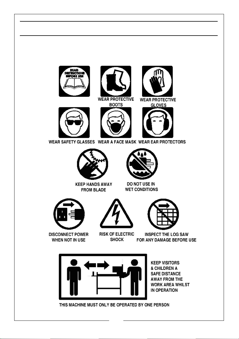
SAFETY SYMBOLS & PICTOGRAMS
Please read all of the safety and operating instructions carefully before using
this product. The following safety symbols may be found on the product.
7
Parts & Service: 020 8988 7400 / E-mail: [email protected] or [email protected]
Page 8
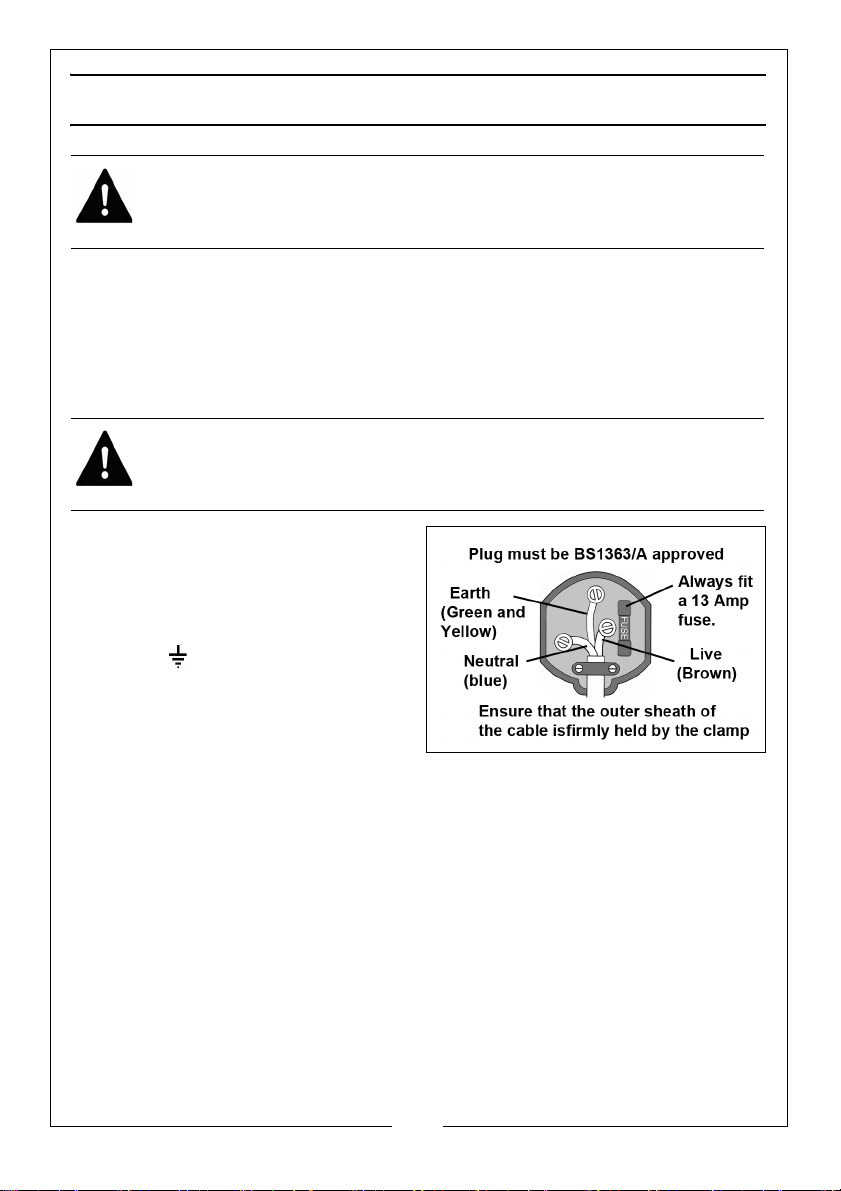
ELECTRICAL CONNECTIONS
WARNING: READ THESE ELECTRICAL SAFETY INSTRUCTIONS
THOROUGHLY BEFORE CONNECTING THE PRODUCT TO THE MAINS
SUPPLY.
Connect the mains lead to a standard, 230 Volt (50Hz) electrical supply
through an approved 13 amp BS1363 plug, or a suitably fused isolator switch.
If the plug has to be changed because it is not suitable for your socket or
because of damage, it must be removed and a replacement fitted, following
the wiring instructions shown below. The old plug must be discarded safely as
insertion into a power socket could cause an electrical hazard.
WARNING: THE WIRES IN THE POWER CABLE OF THIS PRODUCT ARE
COLOURED IN ACCORDANCE WITH THE FOLLOWING CODE:
BLUE = NEUTRAL BROWN = LIVE YELLOW AND GREEN = EARTH.
The wires in the mains lead should be
wired up in accordance with the
following colour code:
• Connect the GREEN & YELLOW
coloured wire to the plug
terminal marked with a letter E
or or coloured GREEN or
GREEN & YELLOW.
• Connect the BROWN coloured
wire to the plug terminal
marked a letter “L” or coloured RED
• Connect the BLUE coloured wire to the plug terminal marked a letter
“N” or coloured BLACK.
We strongly recommend that this machine is connected to the mains supply
via a Residual Current Device (RCD). If you are not sure, consult a qualified
electrician.
DO NOT try to carry out any repairs yourself.
8
Parts & Service: 020 8988 7400 / E-mail: [email protected] or [email protected]
Page 9
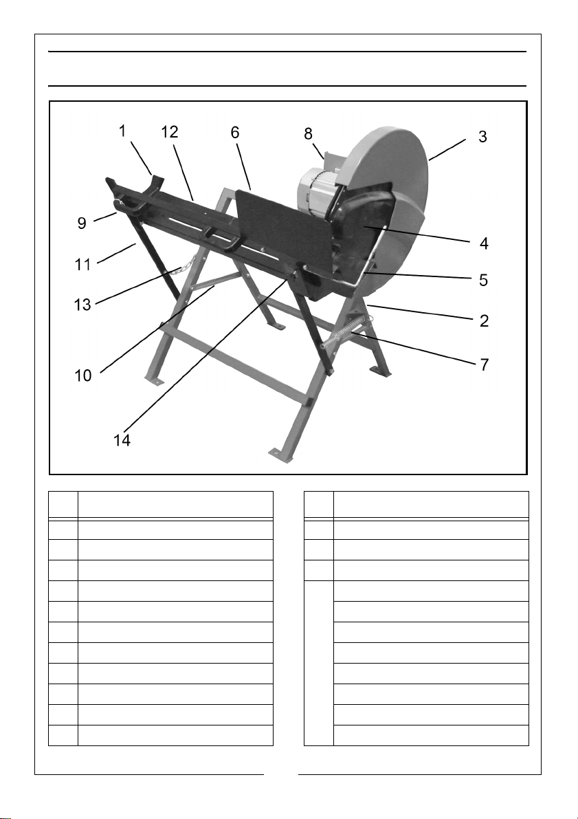
OVERVIEW
NO Description NO Description
1 Log Support Yoke 12 Log Cradle
2 Support Stand 13 Connecting Chain
3 Fixed Guard 14 Securing Knob
4 Moving Guard Other items supplied Loose
5 Log Stop Bar Guard Support Bracket
6 Protective Plate Saw Blade
7 Return Spring Assembly Blade Securing Discs (x2)
8 Motor Stand c/w motor Open Wrench
9 Handle (x2) Blade Locking Wrench
10 Connecting Plate On/Off Switch c/w Cable
11 Cradle Support Arm
9
Parts & Service: 020 8988 7400 / E-mail: [email protected] or [email protected]
Page 10
ASSEMBLY
When unpacking, check for damage or shortages etc. Any found should be
reported to your CLARKE dealer where the product was originally purchased.
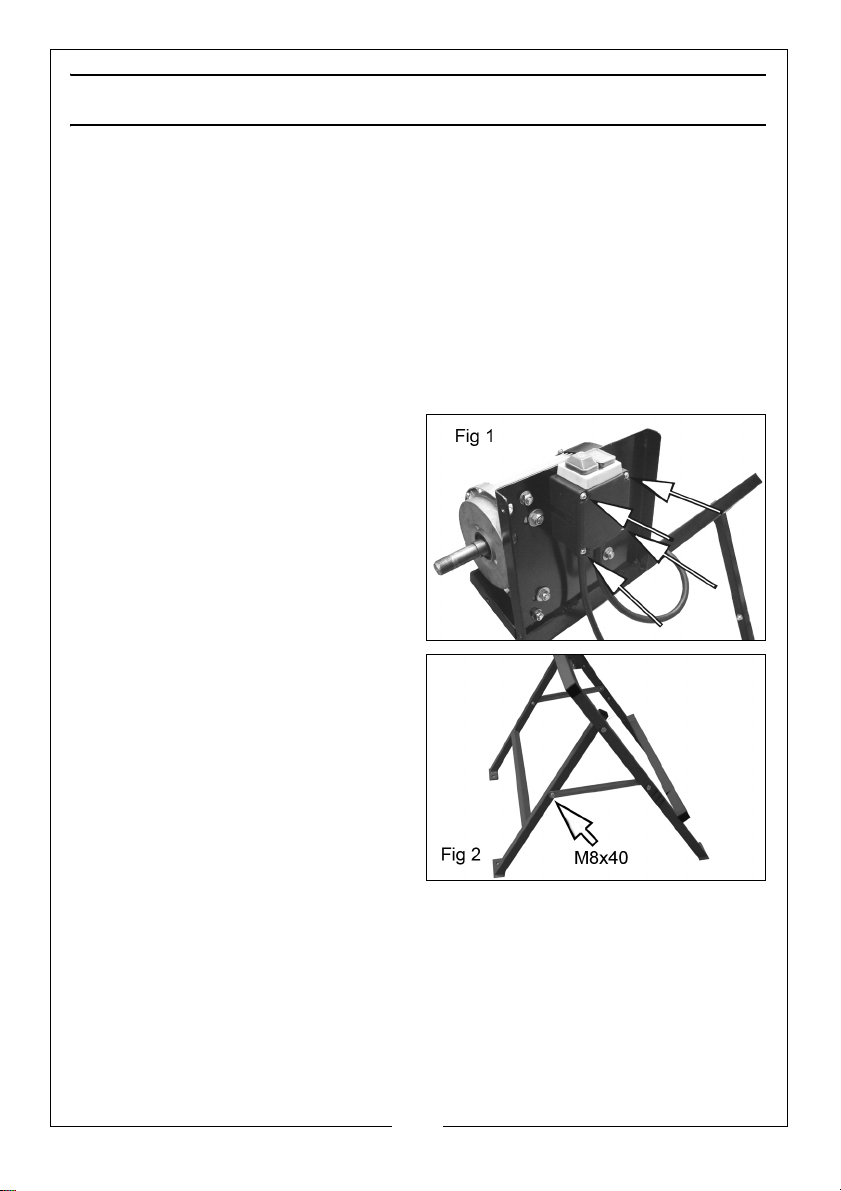
ASSEMBLING THE SWITCH & STANDS
PARTS REQUIRED:
• ON/OFF Switch:- 4 x M4 x 55 mm screws & 4 x M4 washers
• Motor Stand/Support Stand: 4 x M6 x 40 bolts, nuts & washers, nuts &
washers, 2 x M8 x 60 bolts, nuts & washers
• Connecting Plates:-2 x M8 x 40 bolts, locknuts and washers
Refer to the ‘Overview’ illustration
and to Figs 1 & 2.
1. Fit the ON/OFF switch to the Motor
Stand using the 4 x M4 x 55 mm
screws as shown in Fig 1.
2. The Motor Stand and Support
Stand are joined together using
as shown in Fig 2. Fit the
Connecting Plates to the Motor
Stand and Support Stand, using
the M8 x 40 bolts, flat washers and
M8 locknuts.
10
Parts & Service: 020 8988 7400 / E-mail: [email protected] or [email protected]
Page 11
INSTALLING THE FIXED GUARD
PARTS REQUIRED:
• Fixed Guard:- 4 x 8mm washers & locknuts
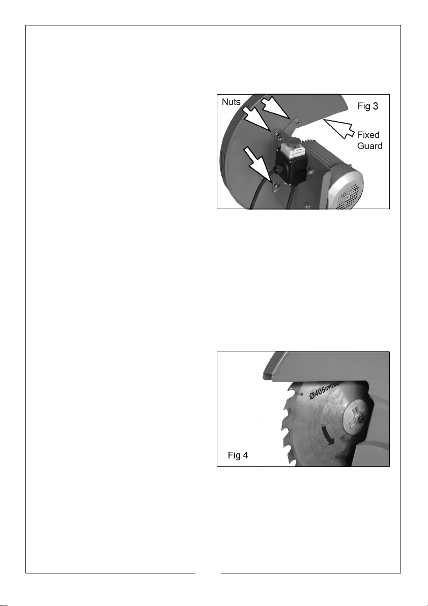
3. Secure the Fixed Guard to the
Motor Stand and fixed Guard
Support Bracket with the four flat
washers and locknuts as in Fig 3.
NOTE: One fixing passes through
the support stand.
INSTALLING THE SAW BLADE
PARTS REQUIRED:
• 1 x M20 Bolt
• 1 x M20 Flat Washer
• 1 x Saw Blade
• Inner/Outer Retaining Discs
•Lower Guard
• 2 x M6 machine screws/washers
1. Slide the Inner Retaining Disc onto
the motor shaft, followed by the
Saw Blade and the Outer
Retaining Disc.
• Install the blade in the
orientation shown in fig 4,
noting the direction of the
arrows on the blade and
ensuring the teeth point in the
direction of rotation shown.
• Do not use a blade with no markings, but if they have become worn
away during previous use, inspect the blade and note the direction of
the teeth. Only use Clarke supplied replacement blades.
• Never use cracked, blunt or otherwise damaged blades.
• Ensure that the blade used is rated at least equal to the speed/
performance of the machine.
11
Parts & Service: 020 8988 7400 / E-mail: [email protected] or [email protected]
Page 12
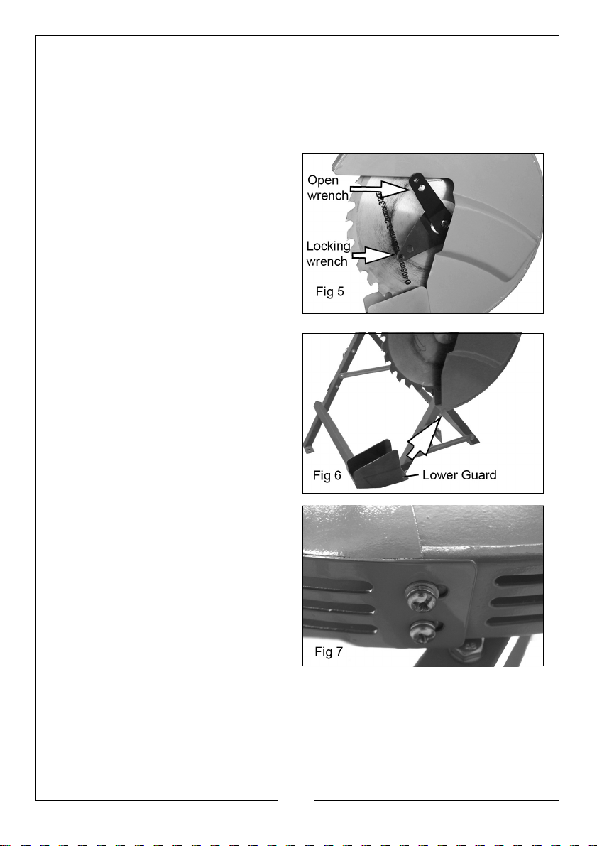
• The blade is designed to sit on a machined shoulder on the drive shaft
and must be in this position before the securing bolt is tightened.
• The outer retaining disc has a flat on one side of the central hole to align
with a flat on the motor shaft.
2. Secure the discs and blade with the flat washer and M20 bolt.
3. Use the Locking Wrench to stop
the blade from turning while
tightening the nut with the Open
Wrench provided as shown in Fig
5.
4. Attach the Lower Guard to the
fixed guard using the M6 machine
screws and washers as shown in
Figs 6 & 7.
12
Parts & Service: 020 8988 7400 / E-mail: [email protected] or [email protected]
Page 13
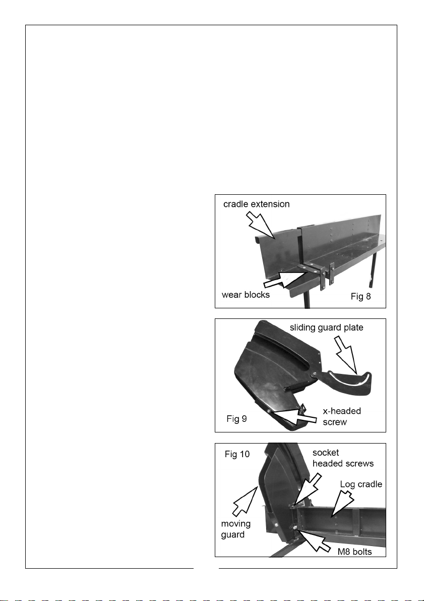
ASSEMBLING THE LOG CRADLE & MOVING GUARD (PARTS REQUIRED:)
• Return Spring Mounting Bracket:- 1 x 40mm bolt, locknut, 2 x washers.
• Return Spring Rod:- 1 x M6 x 40 bolt, locknut, 2 x 6 mm washers, 1 x R-Clip
& 1 x spring.
• Connecting Chain:- 2 x M6 x 40mm bolts, 2 M6 nuts & 4 x washers
• Cradle Support Arms:- 2 x M8 x 60mm bolts, 2 x M8 locknuts & washers.
• Sliding Guard Plate:-1 x locating nut
• Plastic Wear Blocks:-4 x cross-headed grubscrews.
• Moving guard (2 sections):-4 x socket headed screws, 2 x M8 bolts &
washers, 1 x X-headed screw & washers.
1. Connect the log cradle extension
piece to the log cradle using the 4
x socket-headed grubscrews also
used to retain the plastic wear
blocks.
2. Ensure that both halves of the
moving guard are bolted
together with a single X-headed
screw and washers.
3. Ensure that the sliding guard plate
is secured to the moving guard
with a single nut and spacing
washers between the guard plate
and moving guard.
4. Fix the guard asssembly to the log
cradle using the 4 x socket
headed screws and assemble
loosely.
5. Add the 2 x M8 bolts & washers
before tightening all the fixings.
13
Parts & Service: 020 8988 7400 / E-mail: [email protected] or [email protected]
Page 14
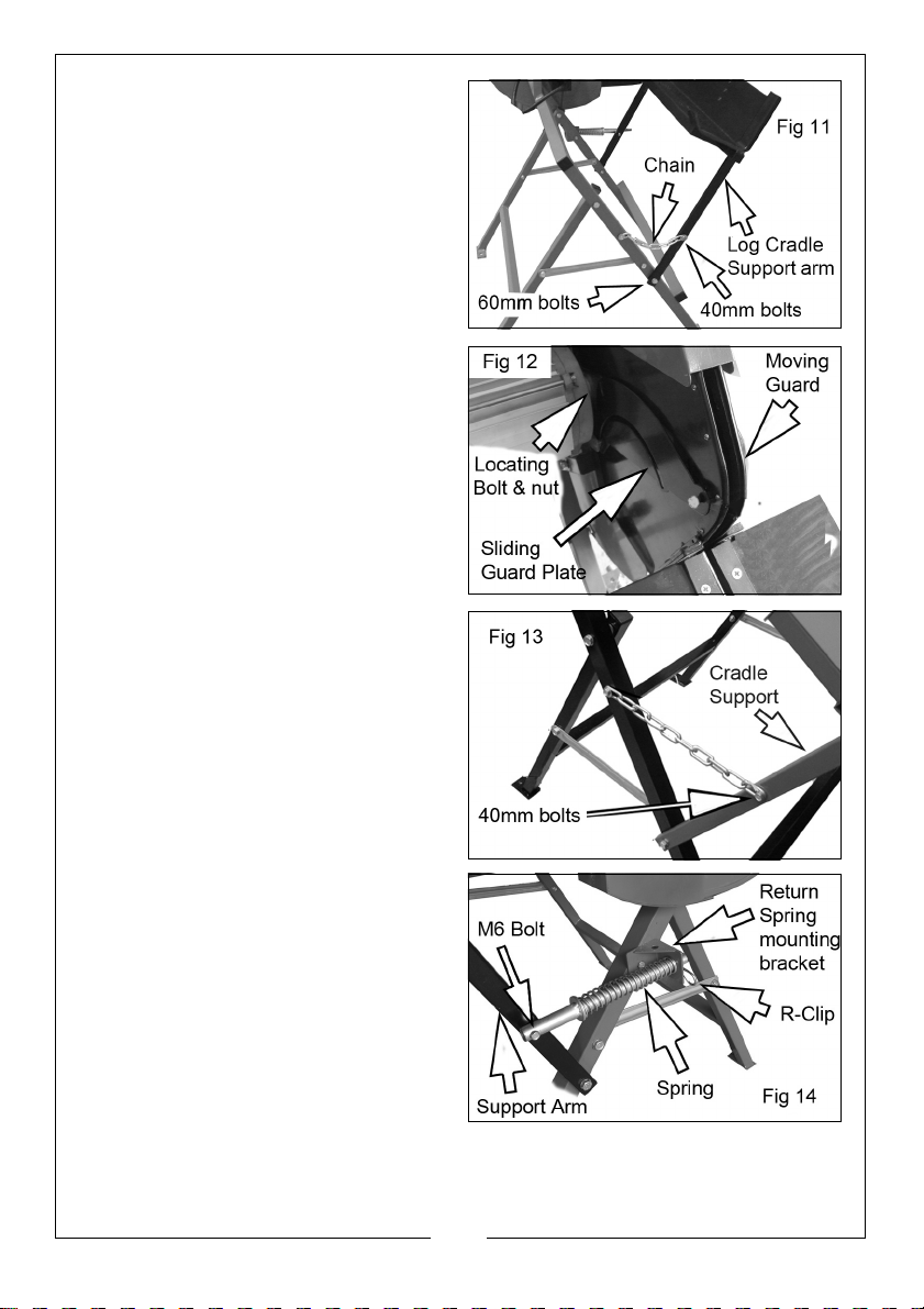
6. Bolt the Log Cradle support arms
to the Support Frame using 60mm
bolts, nuts & washers.
7. Taking the weight of the cradle
assembly, manouvre the sliding
guard plate to engage with the
locating bolt on the fixed guard.
• The sliding guard plate will then
support the weight of the log
cradle assembly.
8. Secure the Connecting Chain
between the cradle support and
support stand using the 40mm
bolts, washers & nuts.
9. Fit the Return Spring Assembly to
the cradle support arm using a
the 40mm bolt, at the same time,
feeding the spring onto the rod
before passing the rod through
the return spring mounting
bracket. Secure the spring
assembly with the R-Clip.
10. Lift the cradle and turn the blade
gently by hand and check it is
passing cleanly through the gap
in the cradle without touching the sides.
14
Parts & Service: 020 8988 7400 / E-mail: [email protected] or [email protected]
Page 15
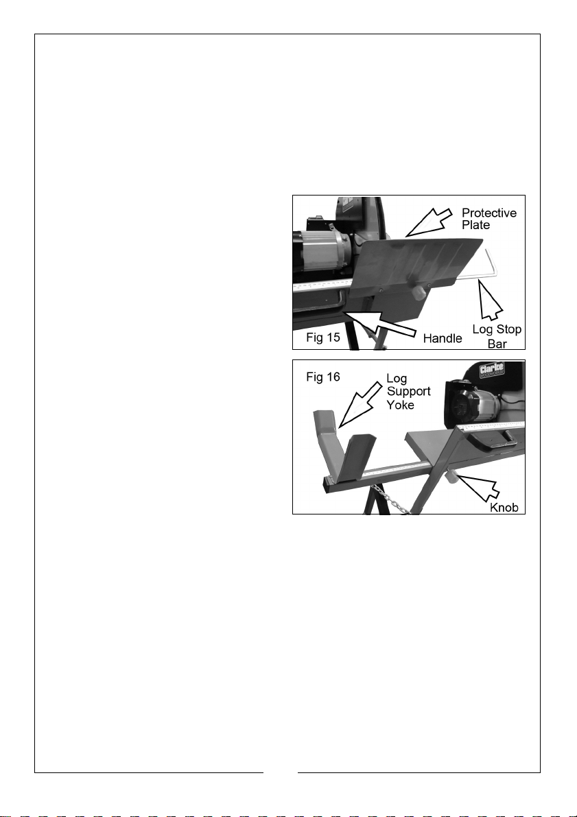
INSTALLING THE HANDLES, PROTECTIVE PLATE & LOG SUPPORT YOKE
PARTS REQUIRED:
• Handles:- 4 x M6 x10 hex headed screws.
• Protective Plate:-2 x M6 x 6 machine screws
• Log Support Yoke
• Log Stop Bar
1. Secure both the handles to the
log cradle with M6 x 10 hex
headed screws.
2. Attach the Protective Plate using
2 x M6 machine screws.
3. Insert the Log Support Yoke into
the cradle and lock in position as
required with the securing knob.
4. Slide in the Log Stop Bar into the
other end of the cradle and set it
in po sition as required by screwing
in the securing knob.
MOUNTING THE SAW TO THE FLOOR
The foot of each leg is provided with a bolt hole for fixing the log saw to a
suitably level floor or platform.
Choose a suitable position close to a convenient power supply and bolt or
screw the stand securely in position. (fixings not supplied)
15
Parts & Service: 020 8988 7400 / E-mail: [email protected] or [email protected]
Page 16
OPERATION
BEFORE STARTING WORK
WARNING: DO NOT PLUG IN TO THE MAINS, UNLESS YOU HAVE ENSURED
THE SAW IS SWITCHED OFF AND THE REMOVABLE BLADE GUARD IS IN
PLACE.
1. Check that all parts are secure. If the log saw is not fixed to the floor, ensure
that it is placed in a steady position on firm ground.
2. Ensure the power cable is well away from the saw and the workpiece
before plugging into the mains supply.
3. Always check that the saw guard and cradle move freely and spring back
when released.
4. Make sure that any timber being sawn does not contain any nails or other
metal objects which would damage the saw blade.
NOTE: The maximum log diameter that can be cut is 135mm.
USING THE SAW
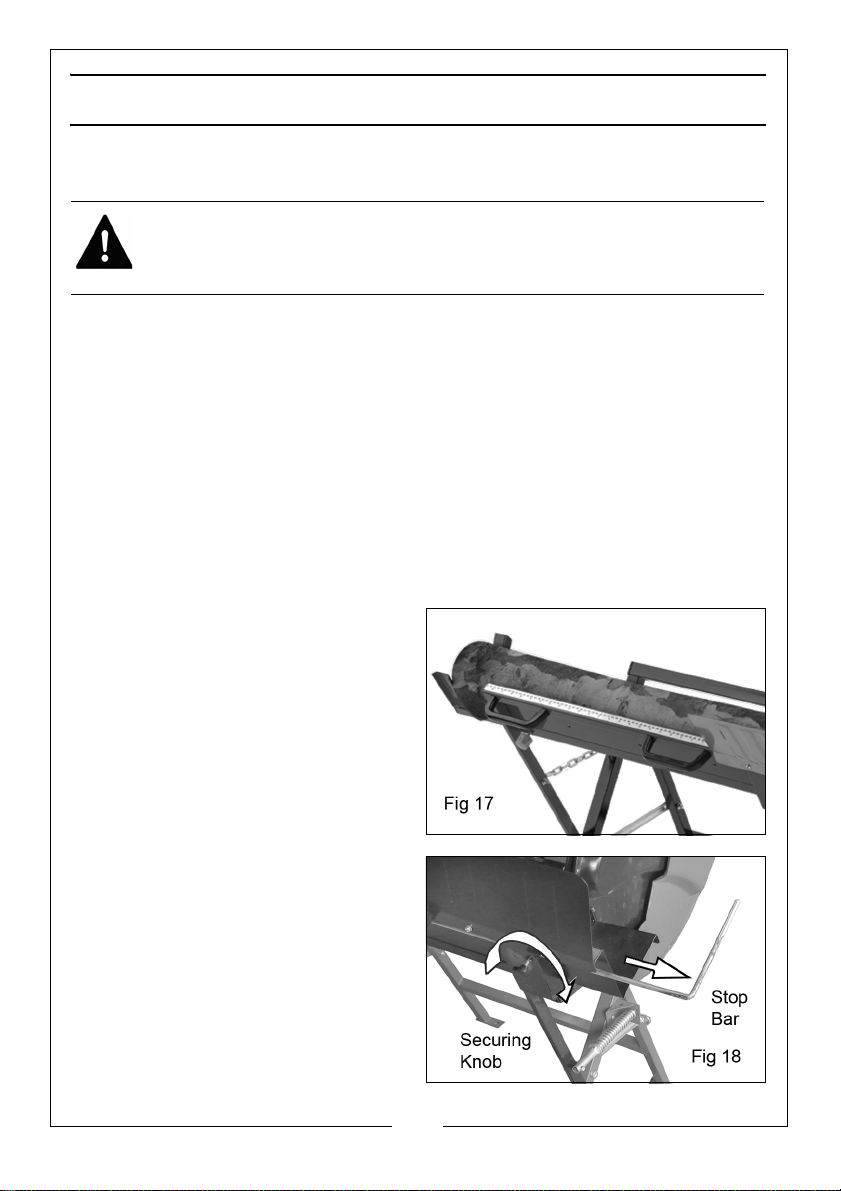
1. Position the workpiece in the
cradle so that it will not move
while cutting.
2. If the length of the log is greater
than the length of the cradle,
extend the log support yoke and
set it’s position to suit with the
securing knob.
3. If logs of equal length are
required, set the log stop bar to
the required distance and lock in
position with the securing knob.
16
Parts & Service: 020 8988 7400 / E-mail: [email protected] or [email protected]
Page 17
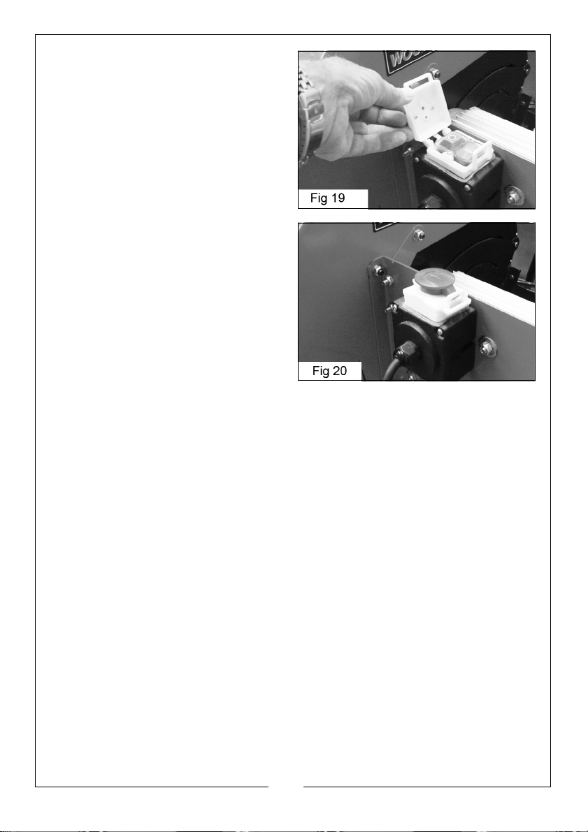
4. Lift the top cover of the On/Off
switch in order to press the green
On button and switch the saw on.
• The top cover should be
opened by pushing the top
forward then lifting.
5. Close the top cover section as
soon as the saw is running but do
not latch it shut. To stop the saw,
press or strike the red top cover
section.
• The saw will stop and the brake
will be applied to the saw
automatically.
6. Hold both handles at all times to
push the workpiece steadily
against the saw blade. Wait for the motor to reach full speed before
cutting. Take care not to let the log bounce against the saw blade. Always
remove the sawn wood before attempting to cut the next piece.
7. Only one piece of wood should be placed on the log cradle for cutting at
any one time.
• Always control the cradle keeping both hands on the handles provided.
When pushing the wood into the saw, take care that the motor speed
does not drop.
• To stop the saw press the OFF switch. Always switch off before
unplugging and never leave the saw running unattended.
8. Avoid putting unnecessary pressure on the blade. Let the blade work
naturally.
• Never try to re-start the saw if the blade becomes jammed in the
workpiece. Switch off and release the jammed log first.
17
Parts & Service: 020 8988 7400 / E-mail: [email protected] or [email protected]
Page 18
CHANGING THE SAW BLADE
CAUTION: ONLY USE SAW BLADES WITH THE CORRECT FITTING AS
SUPPLIED. ALWAYS ENSURE THE SAW IS DISCONNECTED FROM THE
POWER SUPPLY BEFORE INSTALLING/REMOVING THE BLADE.
1. Ensure the saw is disconnected from the power supply. Take care that the
saw blade has cooled down before touching if it has just been in use.
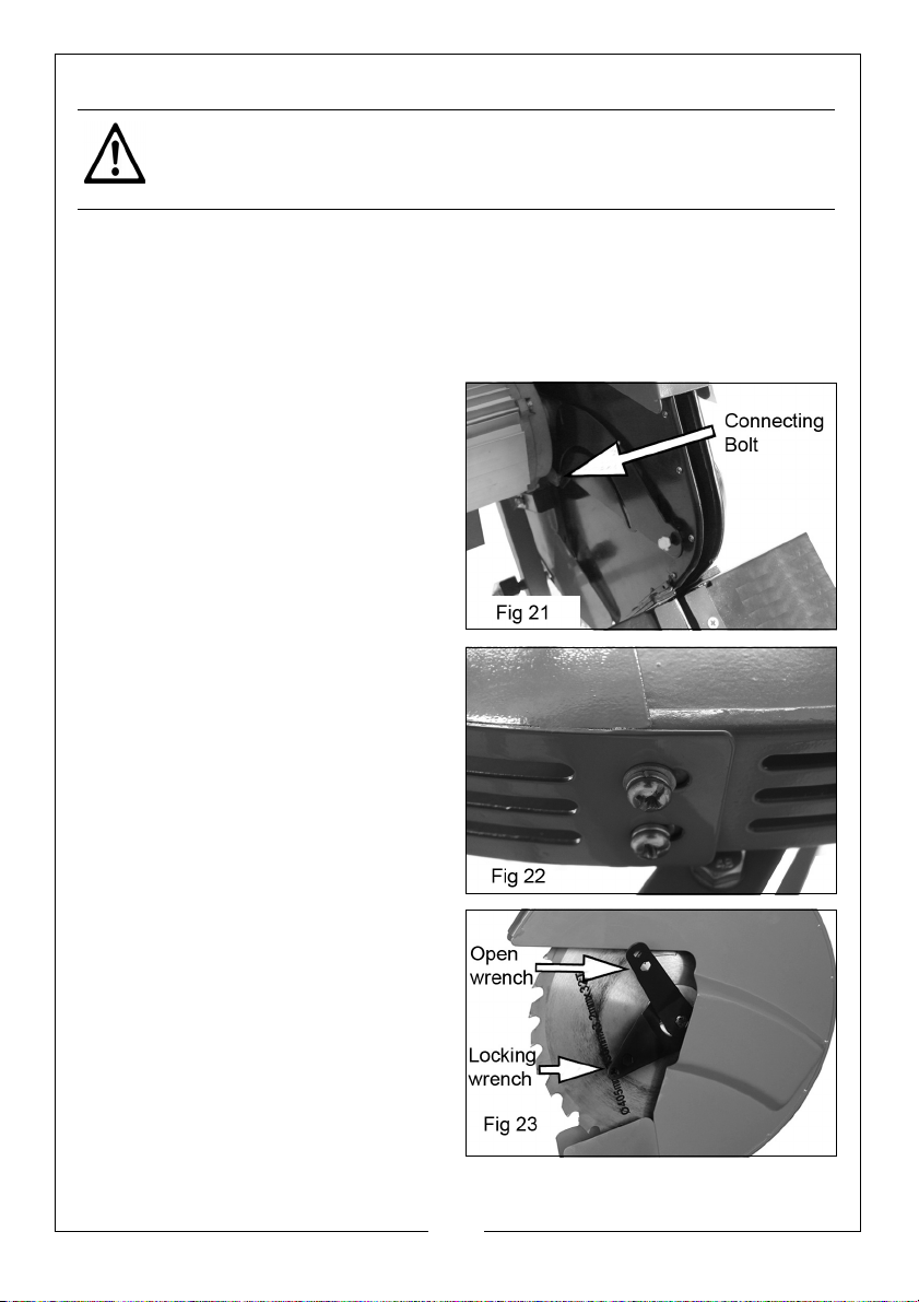
2. Remove the R-Clip from the log carriage return spring shown in Fig 14 and
remove the securing bolt from the safety chain shown in Fig 13.
3. Swing the log cradle away and down to the ground.
4. Detach the sliding guard plate
from the connecting bolt nearest
the motor.
5. To provide enough clearance for
blade removal/replacement, it is
also necessary to remove the
lower guard cover by undoing the
two retaining screws, together
with their locking and plain
washers.
6. Use the blade locking wrench to
prevent the blade from turning
and remove the blade retaining
bolt using the open wrench
provided.
7. Remove the outer retaining disc
and lift away the blade.
8. Brush away any dust or debris
from the spindle before fitting the
new blade.
18
Parts & Service: 020 8988 7400 / E-mail: [email protected] or [email protected]
Page 19

9. Replace in reverse order, ensuring the blade is fitted the right way round
(check the markings and direction of teeth), and that the retaining bolt is
secure. Use the blade locking wrench to stop the blade from turning while
tightening the bolt with the open wrench.
CAUTION: INSTALLING THE BLADE THE WRONG WAY ROUND WILL RESULT
IN DAMAGE TO THE BLADE.
NOTE: Replacement blades are available from your CLARKE dealer as
Part No 3401993.
MAINTENANCE
Always inspect the saw before use and ensure it is in top condition.
Ensure that the guard can spring freely back to its closed position and clean
out any debris lodged behind it.
Check the power cable to ensure it is sound and free from cracks, bare wires
etc.
After use, clean all dust and wood chippings from the saw and its hinged parts
and guards.
Ensure motor air vents are clear of debris, (use compressed air to clean the
machine if possible).
For any problems requiring the dismantling and overhaul of the saw, contact
your CLARKE International Service Department on 020-8988-7400.
STORAGE
Store in a clean, dry environment protected from the weather and away from
children and untrained users.
19
Parts & Service: 020 8988 7400 / E-mail: [email protected] or [email protected]
Page 20
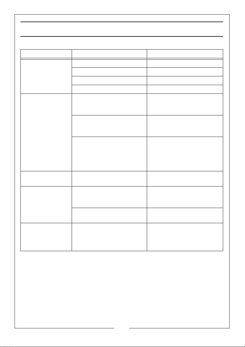
FAULT FI NDI NG
Problem Cause Solution
Machine will not
operate.
Motor becomes
hot.
Heavy internal
sparking.
Excessive vibration Blade not mounted
Burns showing on
the cut timber.
No power supply. Check supply and rectify.
Switch is faulty. Consult your Clark dealer.
Fuse in plug has blown. Check and replace.
Motor is faulty. Consult your Clark dealer.
Unduly heavy use. Reduce the force applied to
the saw. Let the machine do
the work.
Air vents have become
blocked.
Low supply voltage. Ensure supply voltage is
Motor fault such as worn
brushes.
correctly.
Saw motor bearings worn. Return to your Clark dealer
Incorrect or blunt saw
blade.
Clean out air vents using
compressed air or clean
with a dry cloth.
correct. If an extension
cable is used, ensure it is of
the correct rating and is fully
unwound.
Return to your Clark dealer
for repair.
Check seating of blade and
securing discs, and tightness
of retaining nut.
for repair.
Replace blade with the
correct Clarke replacement.
Check and tighten blade as
necessary.
20
Parts & Service: 020 8988 7400 / E-mail: [email protected] or [email protected]
Page 21
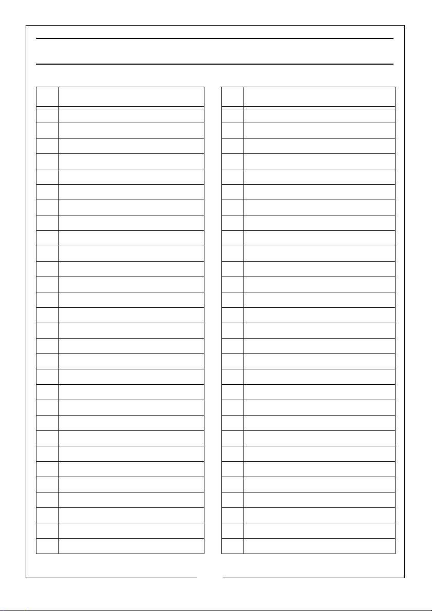
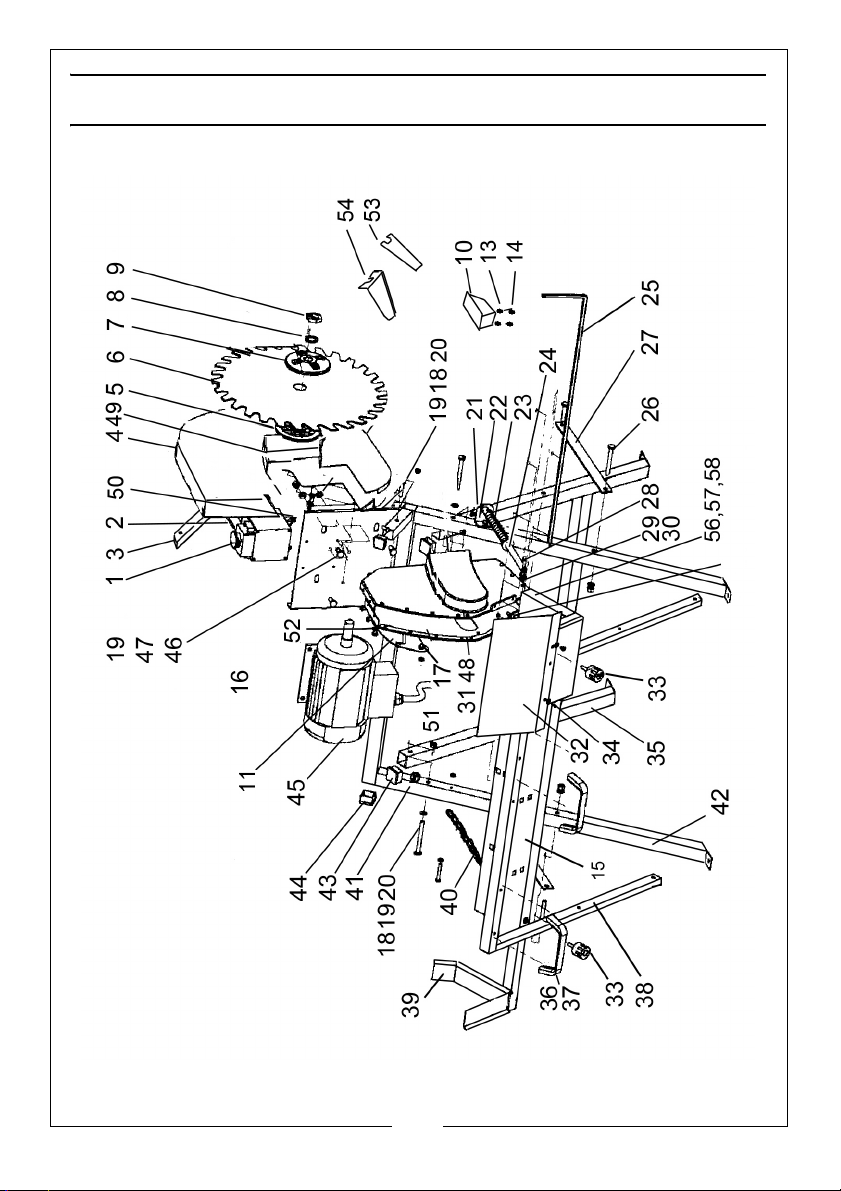
PARTS L IST
NO Description NO Description
1 On/off Switch 30 Washer
2 Screw M4 x 55mm 31 Plastic Guard Wear Strips
3 Fixed Guard Support Bracket 32 Protective Plate
4 Fixed Blade Guard 33 Screw Locking Knob
5 Inner Retaining Disc 34 X-head m/c screw
6 Saw Blade 35 Support Stand
7 Outer Retaining Disc 36 Handle
8 Flat Washer 37 Machine Screw
9 Blade Retaining Bolt 38 Cradle Support Arm
10 Lower Guard 39 Log Support Yoke
11 Sliding Guide Plate 40 Connecting Chain
12 M8 Locknut 41 Spacer
13 Washer 42 Motor Stand Assembly
14 Screw 43 End Cap 20mm
15 Log Cradle 44 End Cap 25mm
16 Moving Guard 45 Motor
17 Spacer 46 M8 Bolt
18 55mm Bolt 47 M8 Washer
19 Washer 48 X-head screw
20 Nut 49 Fibre Pad
21 R-Clip 50 Power Cable
22 Return Spring Bracket 51 Motor Cable
23 Spring 52 Bolt/Locknut (sliding guideplate)
24 Return Spring Rod 53 Open Wrench
25 Log Stop Bar 54 Blade Locking Wrench
26 Bolt 55mm 55 Plastic Wear Strip
27 Connecting Plate 56 Auxilliary Cradle
28 40mm bolt 57 x-headed screw
29 Nut 58 Socket headed screw
21
Parts & Service: 020 8988 7400 / E-mail: [email protected] or [email protected]
Page 22
Page 23
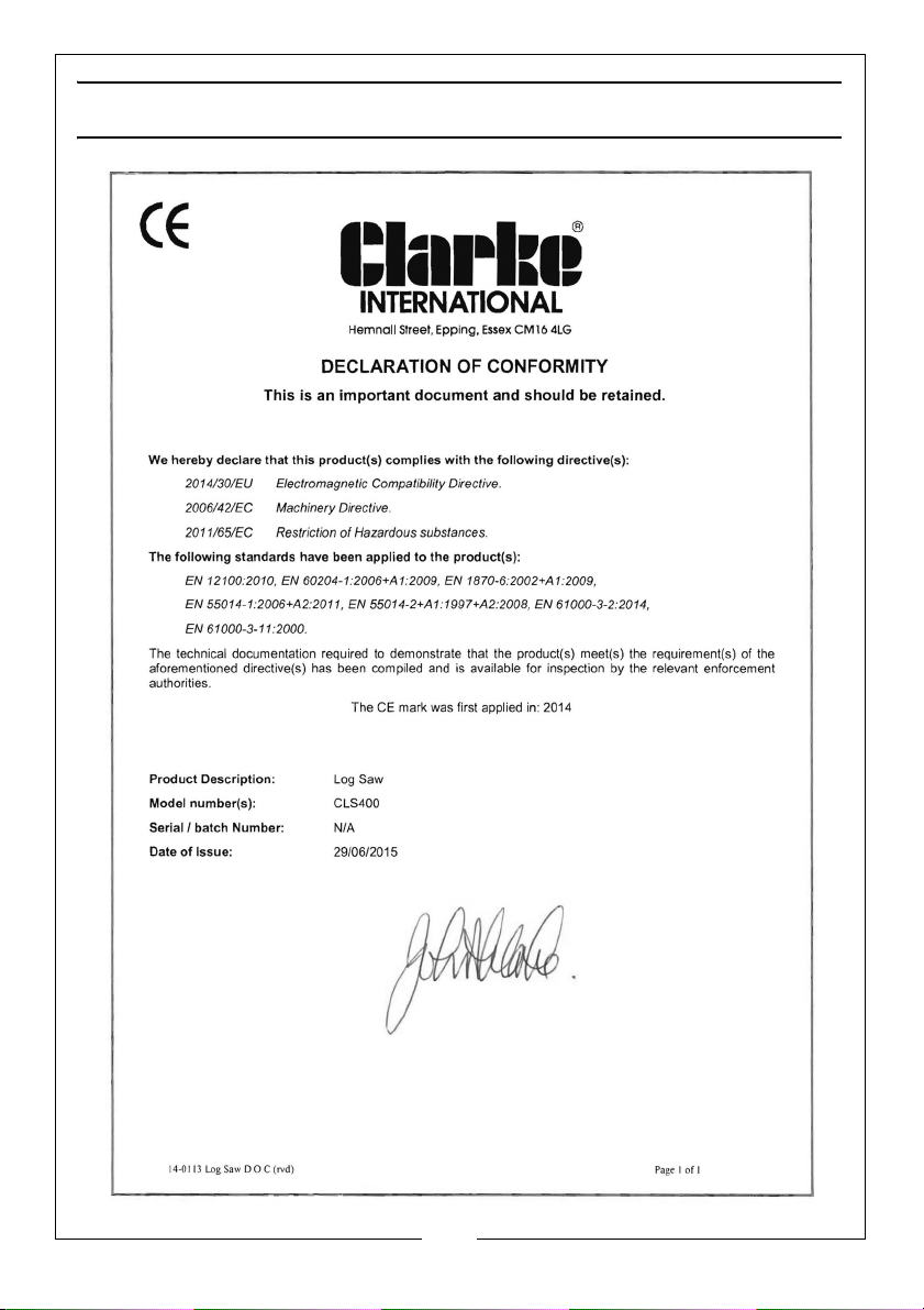
DECLARATION OF CONFORMITY
23
Parts & Service: 020 8988 7400 / E-mail: [email protected] or [email protected]
Page 24

 Loading...