

Page 1
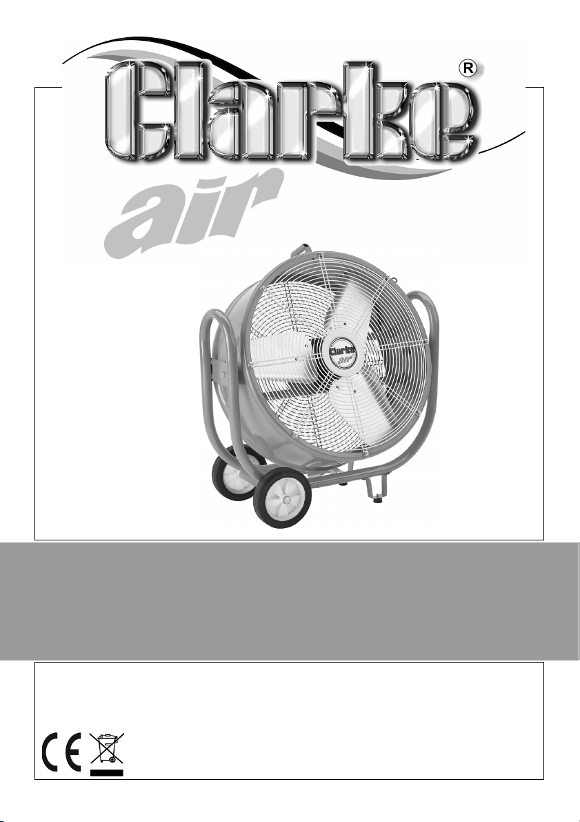
30 INCH DRUM FAN
MODEL NO: CAM110
PART NO: 3231590
OPERATION & MAINTENANCE
INSTRUCTIONS
GC1118 - ISS 3
Page 2
INTRODUCTION
Thank you for purchasing this CLARKE 30” (110V) Drum Fan.
Before attempting to use this product, please read this manual thoroughly and
follow the instructions carefully. In doing so you will ensure the safety of yourself
and that of others around you, and you can look forward to your purchase
giving you long and satisfactory service.
GUARANTEE
This product is guaranteed against faulty manufacture for a period of 12
months from the date of purchase. Please keep your receipt which will be
required as proof of purchase.
This guarantee is invalid if the product is found to have been abused or
tampered with in any way, or not used for the purpose for which it was
intended.
Faulty goods should be returned to their place of purchase, no product can
be returned to us without prior permission. This guarantee does not effect your
statutory rights.
SPECIFICATIONS
MODEL CAM110
Voltage: 110 VAC (50Hz)
Input Wattage: 350 W
Fan Speeds Setting 1 700 rpm
Setting 2 800 rpm
Setting 3 900 rpm
Tilt Range
Max Air Flow
Dimensions (L x W x H): 900 x 330 x 990 mm
Weight: 28.5 kg
Sound Power Measured 75 dB(A) L
2
Parts & Service: 020 8988 7400 / E-mail: [email protected] or [email protected]
O
300
200 m
3
/min
Wa
Page 3
SAFETY PRECAUTIONS
1. Always read the manual before use.
2. Avoid using in dusty environments.
3. Suitable for indoor use only.
4. Do not use in environments containing chemical fumes etc.
5. Do not use as an extractor fan.
6. Do not use in areas of high humidity/water vapour, i.e. bathrooms etc.
7. Do not connect the fan to duct system.
8. Do not cover the fan with clothing or any material that will restrict free
airflow through the fan.
9. Never touch the blades with your hand or any loose object.
10. Always unplug the fan before moving it or performing maintenance. Don’t
touch the fan when your hands are wet.
11. Those who are not qualified electricians should not disassemble, repair or
rebuild the fan.
12. Always unplug the fan when it is not in use.
13. Never unplug the fan by holding the cable. Unplug by holding the plug.
14. Never use the fan if the cable or plug are damaged.
15. Never use the fan close to fires.
16. Do not use this fan with any solid-state speed control device to reduce the
risk of fire or electric shock.
ENVIRONMENTAL RECYCLING POLICY
Through purchase of this product, the customer is taking on the
obligation to deal with the WEEE in accordance with the WEEE
regulations in relation to the treatment, recycling & recovery and
environmentally sound disposal of the WEEE.
In effect, this means that this product must not be disposed of with general
household waste. It must be disposed of according to the laws governing
Waste Electrical and Electronic Equipment (WEEE) at a recognised disposal
facility.
3
Parts & Service: 020 8988 7400 / E-mail: [email protected] or [email protected]
Page 4
ELECTRICAL CONNECTIONS
WARNING! READ THESE ELECTRICAL SAFETY INSTRUCTIONS
THOROUGHLY BEFORE CONNECTING THE PRODUCT TO A
POWER SUPPLY.
This product can be connected to one of the following power supplies:
• 110V Generator
• 110V Isolating Transformer
• 110V Site supply
• 230V Generator via a 110V transformer.
Connecting it to any other power source may cause damage.
This product includes a fitted industrial plug to BS-EN
60309, and a cable for use with a 110 volt supply. On
no account must a 230V, 13amp (BS1363) plug be
used.
If using a portable 110V transformer make sure it has a
rated capacity sufficient to take the load of the fan.
Should the plug need changing at any time, ensure
that a plug of identical specification is used and
proceed as follows:
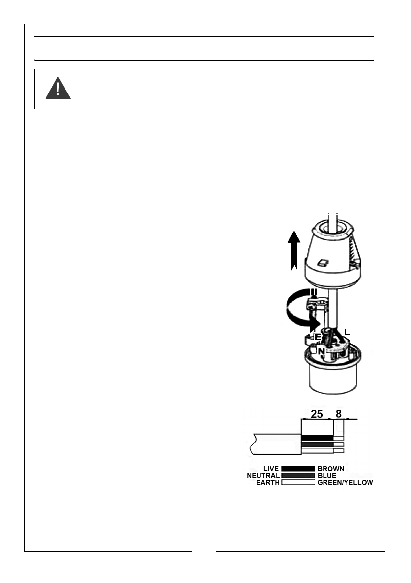
1. Undo the socket screws & remove the rear section.
2. Rotate the cable clamp clear of the terminals.
3. Feed the cable through the rear gland in the plug.
4. Remove the cable sheath to the required lengths
as shown in the diagram.
5. Terminate the correct wires in the
correct terminal blocks as shown.
6. Remove the cable clamp screws. Clip
the cable clamp back into position and
place the clamp around the outer
sheath of the cable. Replace the screws
and tighten until the cable is securely
held.
7. Replace the rear cover and tighten the cover screws.
If in any doubt, consult a qualified electrician. DO NOT attempt any repairs
yourself.
4
Parts & Service: 020 8988 7400 / E-mail: [email protected] or [email protected]
Page 5
CONTENTS
Ensure the fan suffered no damage during transit and that all components are
present. Should any loss or damage be apparent, please contact your CLARKE
dealer immediately. The following components are supplied:
• 1 x Fan Assembly
• 2 x Rubber Feet with Mounting Brackets
• 2 x Moulded Wheels
• 1 x Handle
• Set of Fixing Bolts
ASSEMBLY
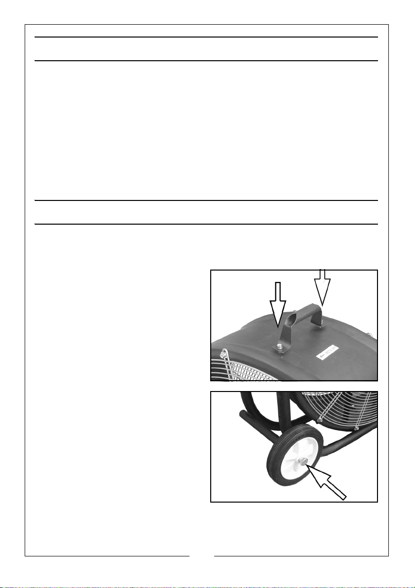
Some assembly is required before using the fan.
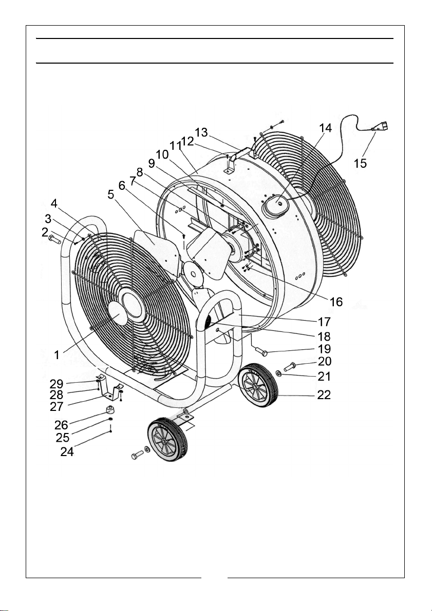
The following part numbers can be found on the parts list on page 9.
1. Fit the handle (item 13) to the fan
housing (item 11) using the screws
(item 12).
2. Fit the wheels (item 22) to the
frame using the bolts (item 20)
and washers (item 21).
5
Parts & Service: 020 8988 7400 / E-mail: [email protected] or [email protected]
Page 6
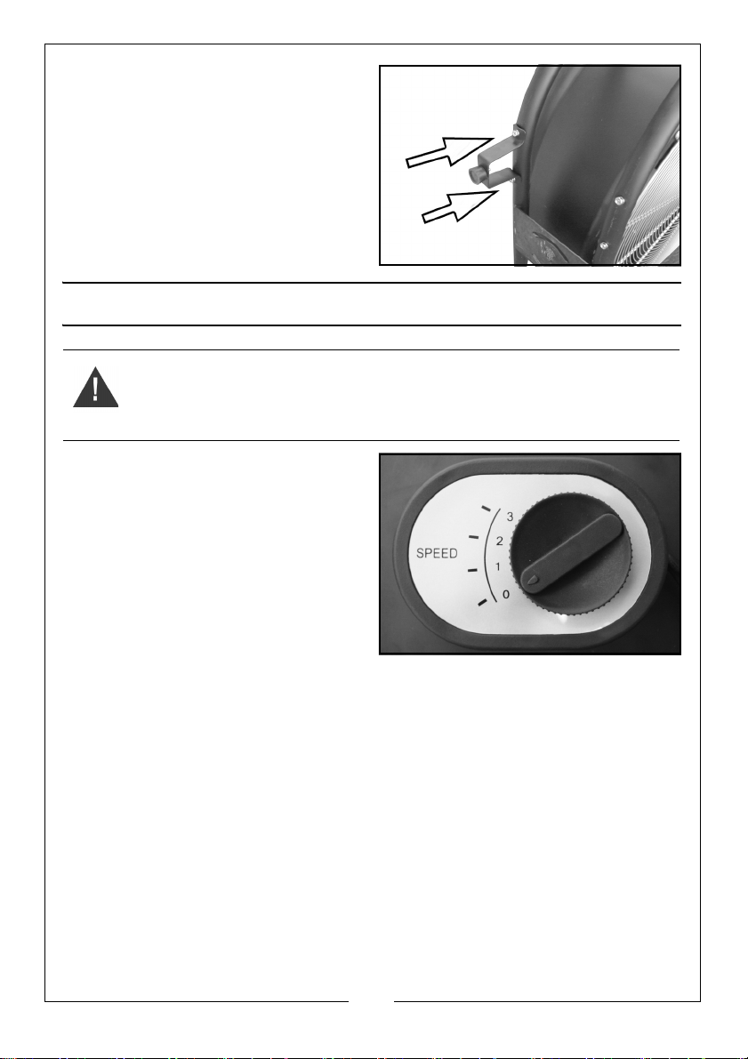
3. Fit the foot brackets (item 27)
using the screws (item 28) and
washers (item 29).
OPERATION
WARNING: NEVER OPERATE THE FAN WITH THE FRONT GRILL
REMOVED.
Plug in to the power supply with the
speed control set to 0, before
adjusting the fan speed as below
Turn the switch on the speed control
to select the fan speed required.
• Position 0 - Off
• Position 1 - 700 rpm
• Position 2 - 800 rpm
• Position 3 - 900 rpm
.
6
Parts & Service: 020 8988 7400 / E-mail: [email protected] or [email protected]
Page 7
MAINTENANCE
WARNING: ALWAYS DISCONNECT THE POWER CABLE FROM THE POWER
SUPPLY BEFORE PERFORMING MAINTENANCE WORK
• The motor bearings are permanently sealed for life and do not
require any additional lubrication.
• Have any repairs carried out by a suitably qualified person.
CLEANING
If the fan has been operating for long periods in a very dusty environment, the
blades and motor assembly may eventually require cleaning.
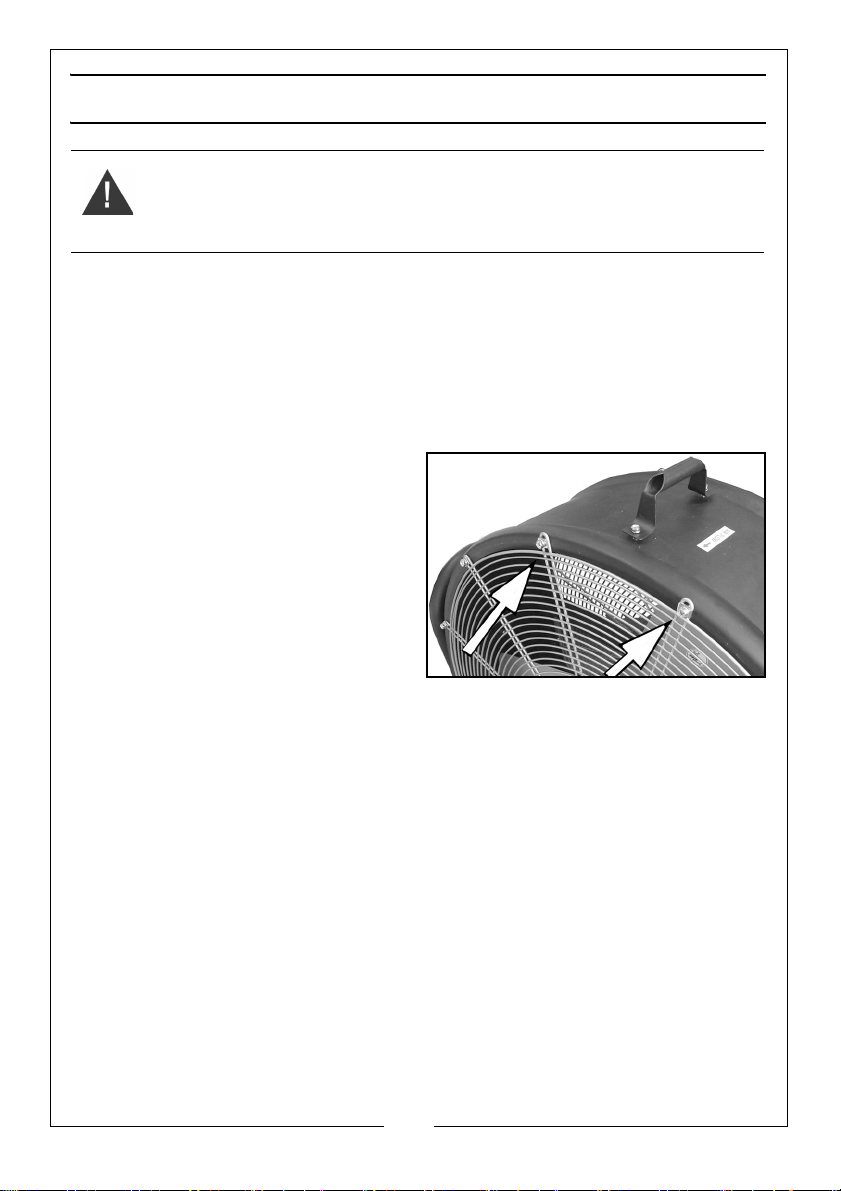
1. Unscrew the front grill and lift it
away carefully.
2. Wipe the fan blades with dry cloth
and remove any dust from the
motor assembly with a soft
paintbrush, vacuum cleaner or jet
of compressed air.
• Never use polish or any
corrosive liquid that will
damage the surface finish.
3. Replace the grill securely before use.
7
Parts & Service: 020 8988 7400 / E-mail: [email protected] or [email protected]
Page 8
Page 9
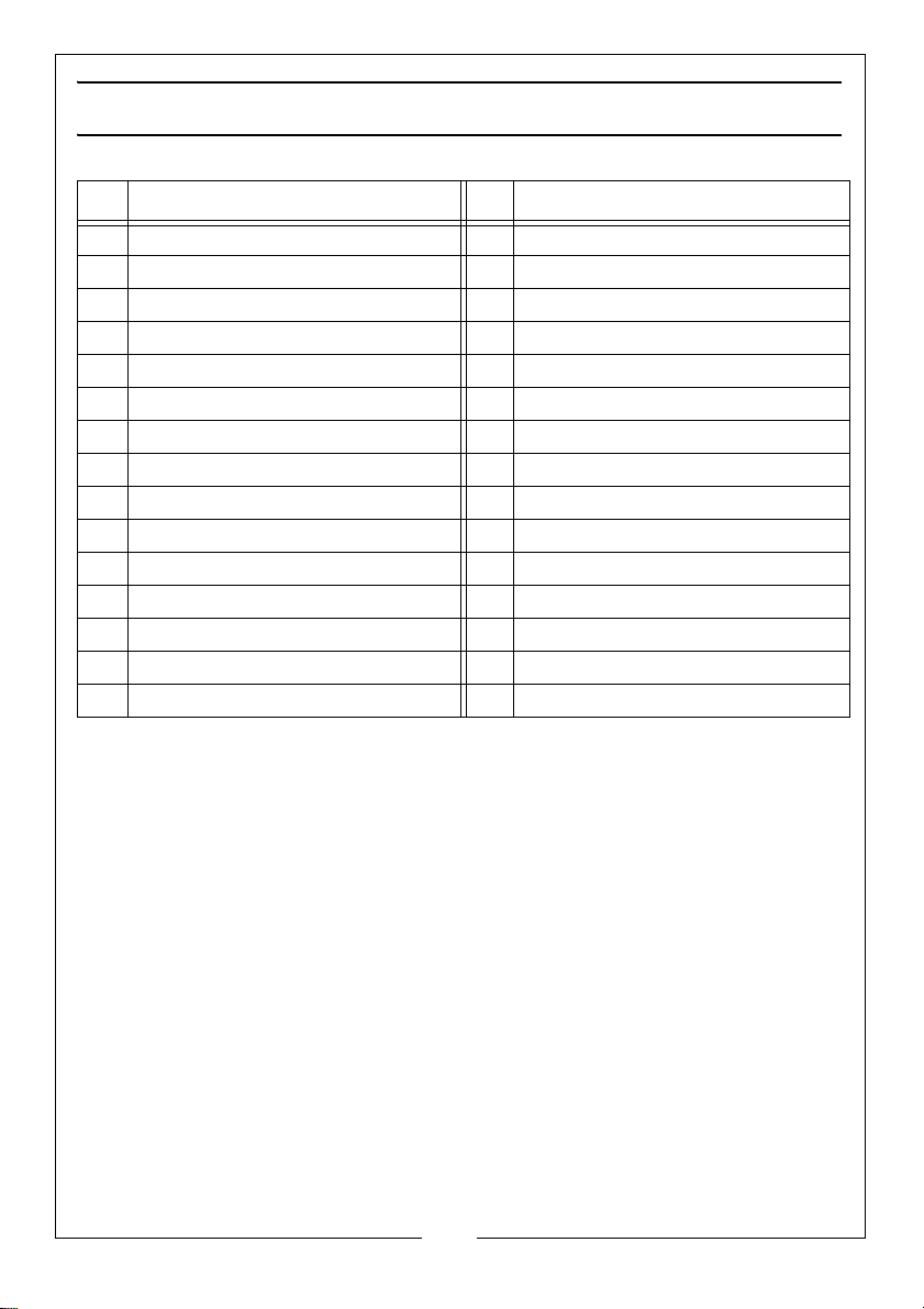
COMPONENT PARTS
NO DESCRIPTION NO DESCRIPTION
1 Brand Name Plate 16 Screw st4 x 12
2 Bolt M16 x 12 17 Steel Pipe
3 Washer 6mm 18 Shock Absorber
4. Front/Rear Grill 19 Bolt M12 x 36
5 Fan Blade 20 Bolt M12 x 70
6 Screw M10 x 13 21 Washer 12mm
7 Motor 22 Wheel
8 Screw M6 x 12 23 n/a
9 Nut M6 24 Screw M5 x 10
10 Nut M6 25 Washer 5mm
11 Drum Fan Housing 26 Foot
12 Screw M6 x 12 27 Foot Bracket
13 Handle 28 Screw M6 x 12
14 Switch Box 29 Washer 6mm
15 Power Cable
9
Parts & Service: 020 8988 7400 / E-mail: [email protected] or [email protected]
Page 10
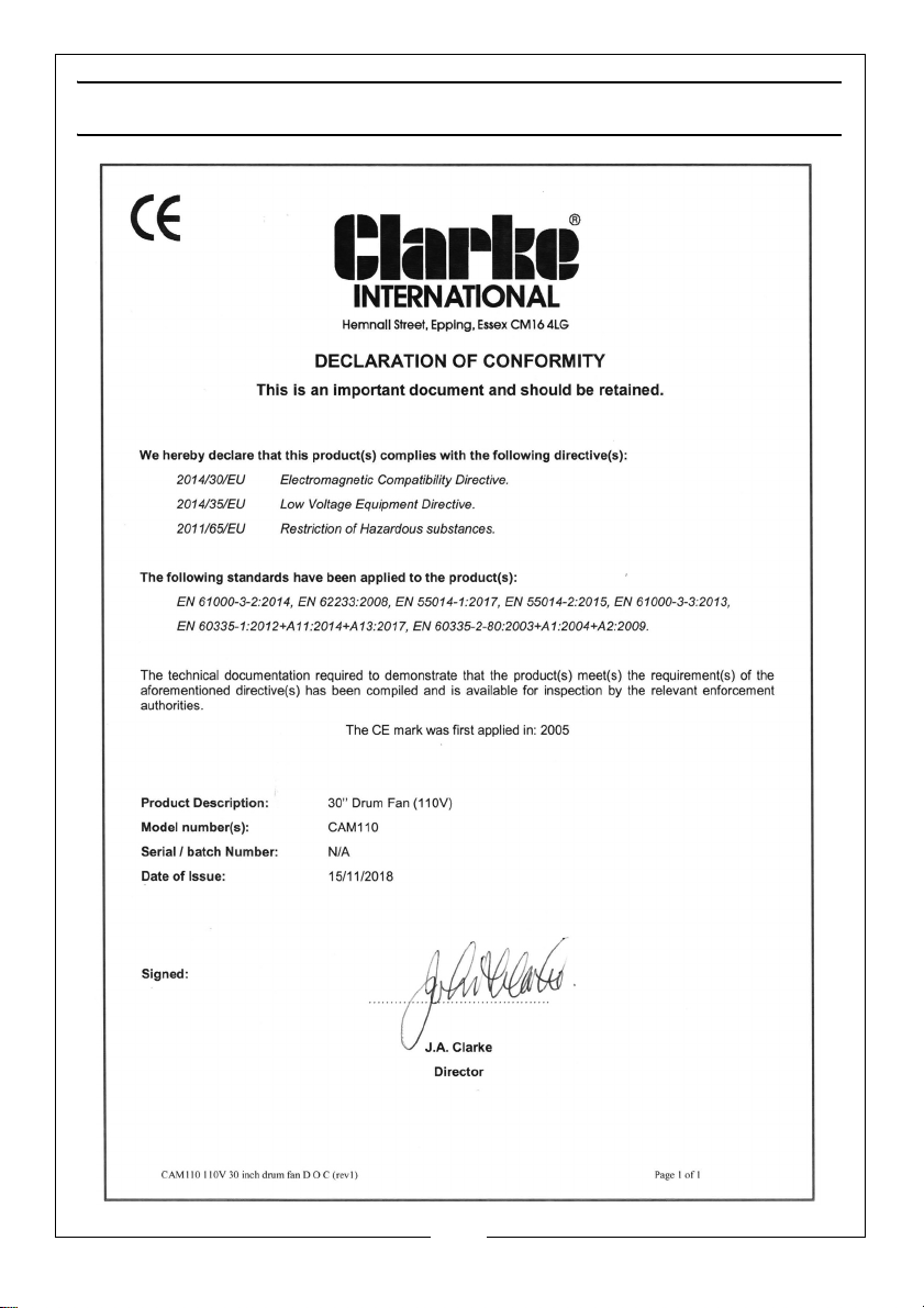
DECLARATION OF CONFORMITY
10
Parts & Service: 020 8988 7400 / E-mail: [email protected] or [email protected]
Page 11
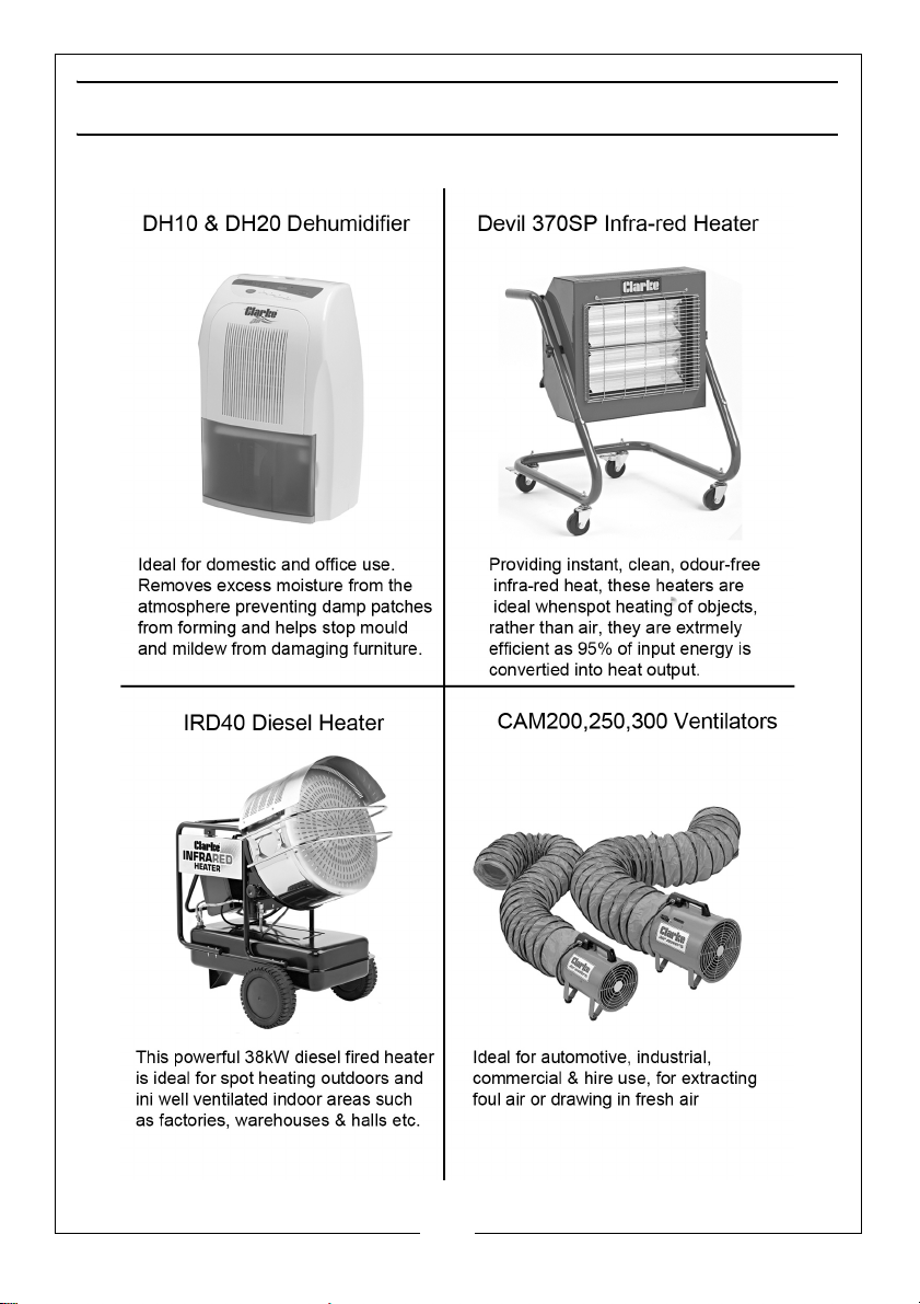
RELATED CLARKE PRODUCTS
11
Parts & Service: 020 8988 7400 / E-mail: [email protected] or [email protected]
Page 12

___________________________________________________________________________
 Loading...