

Page 1
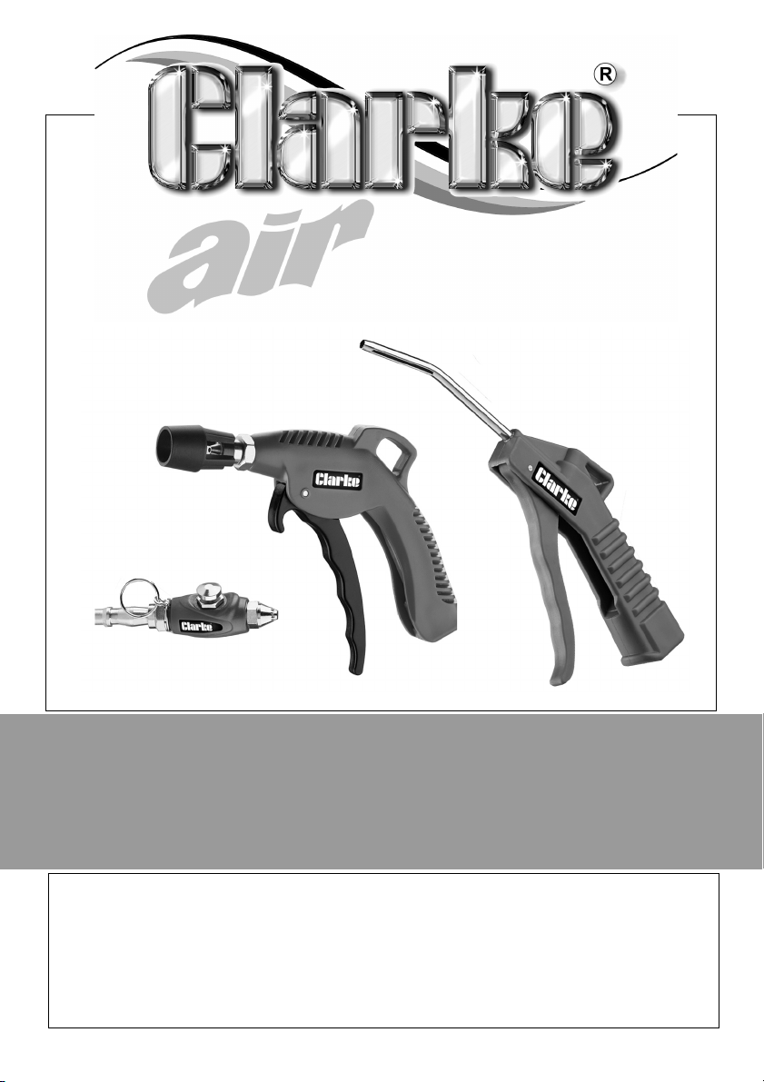
3PC AIR BLOW GUN KIT
MODEL NO: CAT211
PART NO: 3120528
OPERATING & MAINTENANCE
INSTRUCTIONS
ORIGINAL INSTRUCTIONS GC1019 - ISS 1
Page 2
INTRODUCTION
Thank you for purchasing this CLARKE Blow Gun kit.
Before attempting to use this product, please read this manual thoroughly and
follow the instructions carefully. In doing so you will ensure the safety of yourself
and that of others around you, and you can look forward to your purchase
giving you long and satisfactory service.
Please keep these instructions in a safe place for future reference.
SPECIFICATION
Max Operating Pressure 90 psi (6.2 bar)
Air Inlet Size 1/4“BSP Female
Air Consumption 9.5 cfm (max @90psi)
Dimensions Pocket Blow Gun - 97 x 20 x 29mm (0.057kg)
Short nozzle Blow Gun - 130 x 140 x 21mm (0.13kg)
Long nozzle Blow Gun - 240 x 17 x 87mm (0.085kg)
COMPRESSED AIR REQUIREMENTS
WARNING: COMPRESSED AIR CAN BE DANGEROUS. ENSURE THAT YOU
ARE FAMILIAR WITH ALL PRECAUTIONS RELATING TO THE USE OF
COMPRESSORS AND COMPRESSED AIR SUPPLY.
Use only clean, dry, regulated compressed air as a power source.
A build-up of moisture or oil in the air compressor will accelerate wear and
corrosion in the tool. Ensure any moisture is drained from the compressor daily
and the inlet filter is kept clean.
If an unusually long air hose is required, (over 8 metres), the line pressure or the
hose inside diameter may need to be increased.
The hose must be rated at 150% of the max operating pressure of the tool.
If an automatic in-line filter/regulator is used, it will keep the tool in good
condition, but should be regularly checked.
Never exceed the maximum operating pressure for the air tool. It is
recommended that air pressure to this tool does not exceed 90 psi. Higher
pressures and dirty air will shorten the life of the tool due to faster wear and is a
possible safety hazard
2
Parts & Service: 020 8988 7400 / E-mail: [email protected] or [email protected]
Page 3
GENERAL SAFETY RULES
CAUTION: FAILURE TO FOLLOW THESE PRECAUTIONS COULD RESULT IN
PERSONAL INJURY AND/OR DAMAGE TO PROPERTY.
THE WORK ENVIRONMENT
1. Keep the work area clean and tidy.
2. Dress appropriately - Do not wear loose clothing or jewellery. Tie long hair
out of the way.
3. Keep children and visitors away - Do not let children handle the tool.
USE OF AIR POWERED TOOLS
1. Stay alert and use common sense - do not operate this air tool when you
are tired or under the influence of alcohol, drugs or medication.
2. Always wear eye protectors when using the air tool. Eye protectors must
provide protection from flying particles from the front and the side.
3. DO NOT use the blow gun when other persons or animals are nearby or
may be hit by flying debris caused by the blow gun.
4. DO NOT overreach - Keep proper footing and balance at all times.
5. Never use oxygen, CO
a source of power for this blow gun.
6. DO NOT connect the air supply hose with your finger on the trigger.
7. DO NOT exceed the maximum pressure for the air tool of 90 psi / 6.2 bar.
8. Keep the air supply hose away from heat, oil and sharp edges.
9. DO NOT fit the blow gun to a stand/clamping device that may damage it.
10. Check air hoses for leaks or worn condition before use and ensure that all
connections are secure.
11. Do not use the blow gun for any purpose than that described here.
12. DO NOT carry out any alterations or modifications to the blow gun.
13. Always disconnect from the air supply when performing any maintenance.
14. DO NOT use the blow gun if it is defective or operating abnormally.
15. Always maintain your blow gun with care.
16. DO NOT discharge this blow gun at any persons or animals.
2
, combustible gasses or any type of bottled gas as
3
Parts & Service: 020 8988 7400 / E-mail: [email protected] or [email protected]
Page 4
17. DO NOT insert into any part of yours or anyone else’s body.
18. DO NOT point directly at a person’s skin or at a fire.
19. DO NOT carry the blow gun by the hose or with your finger on the trigger.
20. When not in use the blow gun must be disconnected from the air supply
and stored in a dry place out of the reach of children.
21. DO NOT store the blow gun where the temperature is below 0
o
C.
CONNECTING /DISCONNECTING THE AIR SUPPLY
1. Connect a suitable hose to the air inlet.
2. Connect the other end of the air hose to the air compressor.
3. Turn on the air supply and check for air leaks. Rectify any found before
proceeding.
• PTFE tape may be useful for sealing threaded connections.
4. Your blow gun is now ready for use.
5. Set the compressed air pressure to suit at the compressed airline regulator.
6. DO NOT disconnect the air supply hose until the compressed air has been
isolated at a shut off valve. Once the pressure has been released,
disconnect the air supply hose.
MAINTENANCE
WARNING: MAKE SURE THAT THE BLOW GUN IS DISCONNECTED FROM THE
AIR SUPPLY BEFORE STARTING ANY CLEANING OR MAINTENANCE
PROCEDURES.
1. Before use, drain any condensate from the airline filter and compressor.
2. Clean thoroughly after use with a suitable solvent.
Please note that outside factors may affect the blow gun operation and
efficiency. These include reduced compressor output, excessive drain on the
airline, moisture or restrictions in the air-line, or the use of connectors of
improper size or poor condition which will reduce air supply.
Your CLARKE blow gun has been designed to give long and trouble free
service. If, however, having followed the instructions in this booklet carefully,
you encounter problems, take the product to your local CLARKE dealer.
4
Parts & Service: 020 8988 7400 / E-mail: [email protected] or [email protected]
Page 5
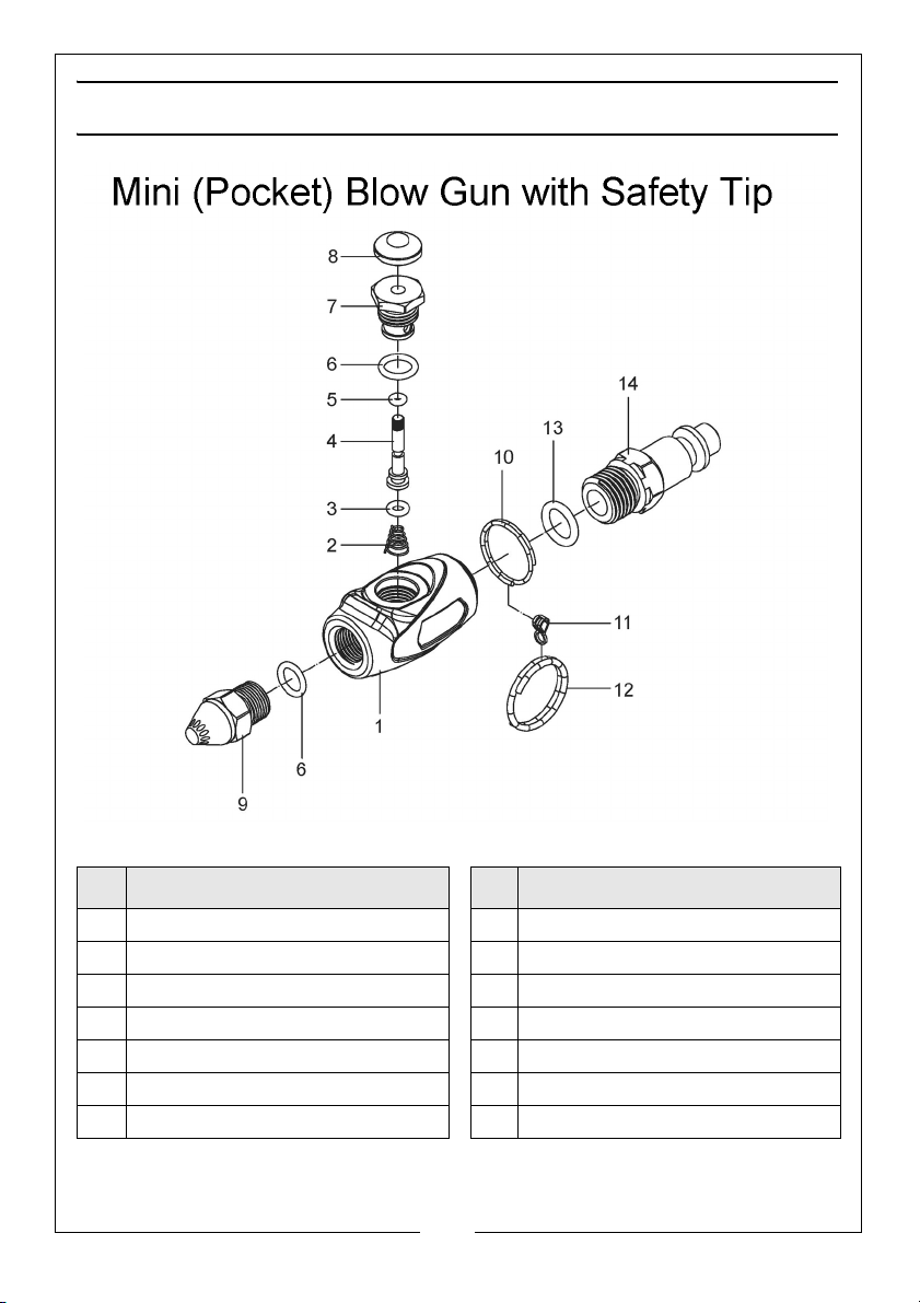
COMPONENT PARTS
No Description No Description
1 Main Housing 8 Button
2 Spring 9 Nozzle
3O-ring 10Large ring
4 Valve stem 11 Small ring
5O-ring 12Large ring
6 O-ring 13 O-ring
7 Valve seat 14 Air inlet
5
Parts & Service: 020 8988 7400 / E-mail: [email protected] or [email protected]
Page 6
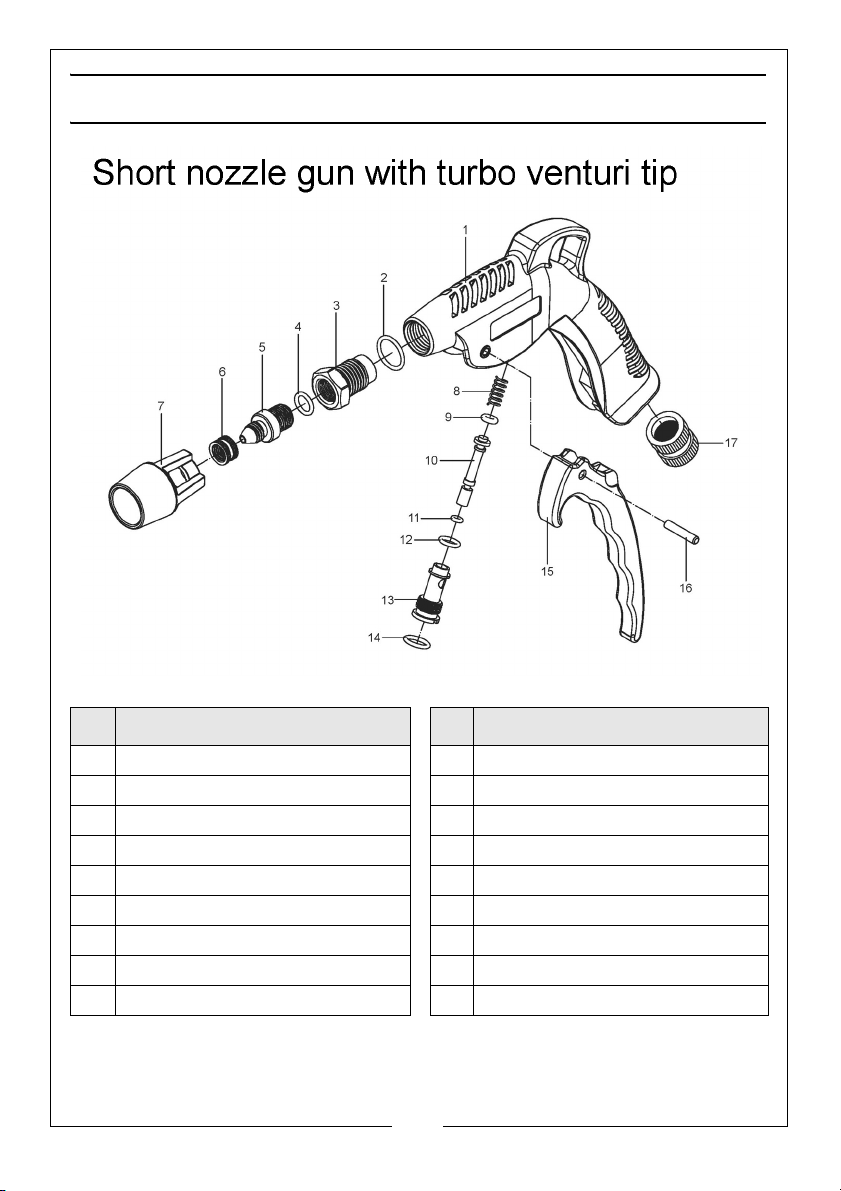
COMPONENT PARTS
No Description No Description
1 Main Housing 10 Valve stem
2 O-ring 11 O-ring
3 Connector 12 O-ring
4 O-ring 13 Small ring
5 Nozzle 14 Large ring
6 Nozzle sleeve 15 Trigger
7 Venturi tip 16 Pin
8 Spring 17 Air inlet
9 O-ring
6
Parts & Service: 020 8988 7400 / E-mail: [email protected] or [email protected]
Page 7
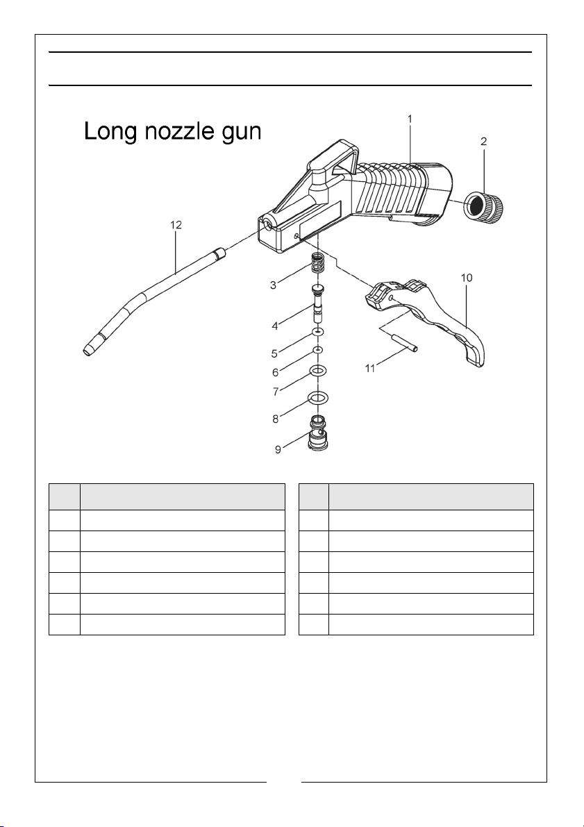
COMPONENT PARTS
No Description No Description
1 Main Housing 7 O-ring
2 Air inlet 8 O-ring
3 Spring 9 Valve seat
4 Valve stem 10 Trigger
5 O-ring 11 Pin
6 O-ring 12 Air nozzle
7
Parts & Service: 020 8988 7400 / E-mail: [email protected] or [email protected]
Page 8
 Loading...