

Page 1
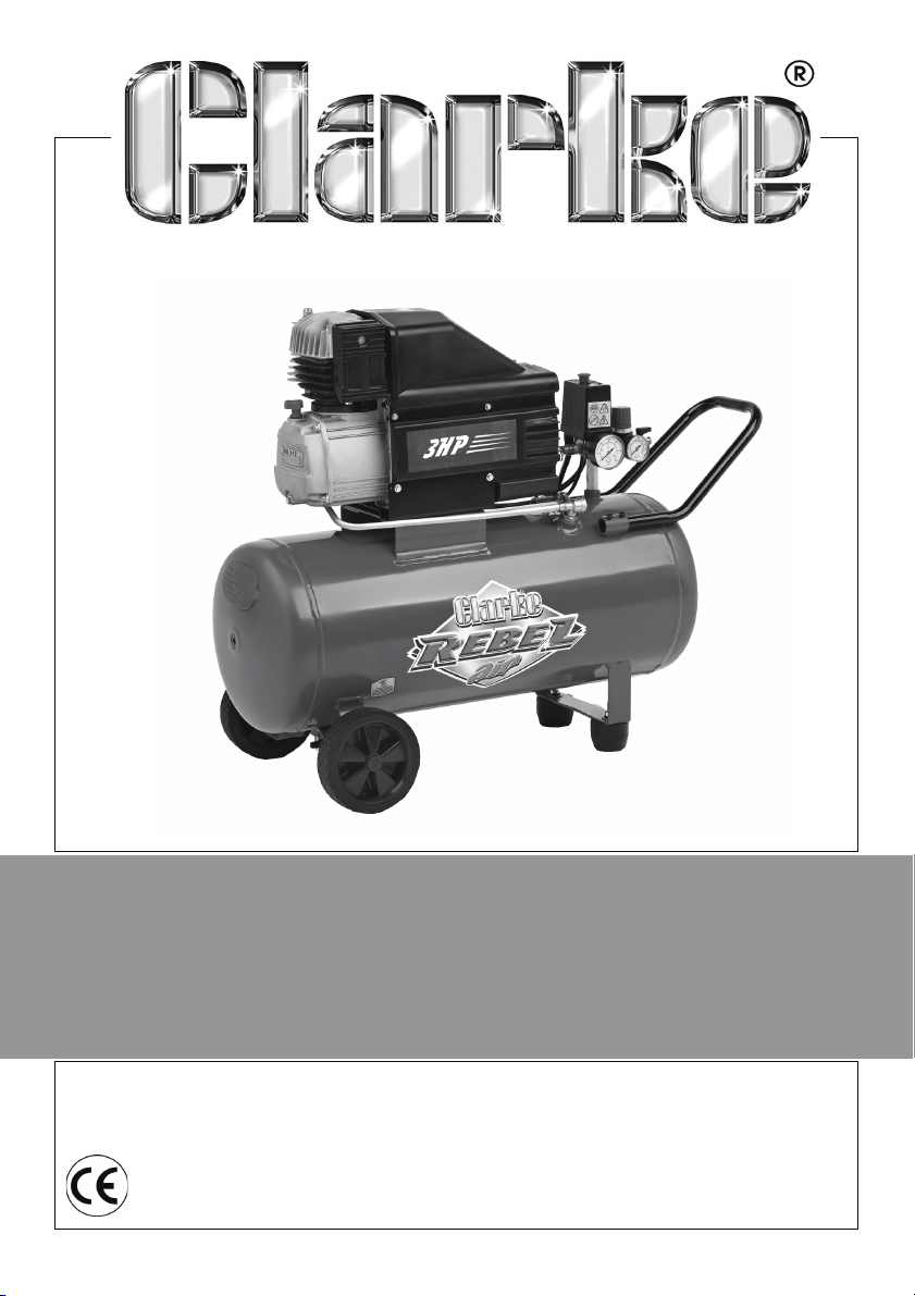
COMPRESSOR
MODEL NO: REBEL 55
PART NO: 2323005
OPERATION & MAINTENANCE
INSTRUCTIONS
LS0512
Page 2
INTRODUCTION
For Parts & Servicing, please contact your nearest dealer, or
CLARKE International, on one of the following numbers.
PARTS & SERVICE TEL: 020 8988 7400
PARTS & SERVICE FAX: 020 8558 3622
or e-mail as follows:
PARTS: [email protected]
SERVICE: [email protected]
Thank you for purchasing this CLARKE Compressor.
Before attempting to use this product, please read this manual thoroughly and
follow the instructions carefully. In doing so you will ensure the safety of yourself
and that of others around you, and you can look forward to your purchase
giving you long and satisfactory service.
GUARANTEE
This product is guaranteed against faulty manufacture for a period of 12
months from the date of purchase. Please keep your receipt which will be
required as proof of purchase.
This guarantee is invalid if the product is found to have been abused or
tampered with in any way, or not used for the purpose for which it was
intended.
Faulty goods should be returned to their place of purchase, no product can
be returned to us without prior permission.
This guarantee does not effect your statutory rights.
PARTS AND SERVICING
Parts & Service: 020 8988 7400 / E-mail: [email protected] or [email protected]
2
Page 3

SAFETY PRECAUTIONS
Before using your compressor it is in your own interest to read and pay attention
to the following safety rules
1. Compressed air is dangerous. NEVER direct a jet of air at people or animals, and
NEVER discharge compressed air against the skin.
2. DO NOT operate your compressor with any guards removed.
3. Electrical or mechanical repairs should only be carried out by a qualified engineer. If
problems occur, contact your Clarke dealer.
4. Before carrying out any maintenance, ensure the pressure is expelled from the air
receiver, and the machine is disconnected from the electrical supply.
5. DO NOT leave pressure in the receiver overnight, or when transporting.
6. DO NOT adjust, or tamper with the safety valves. The maximum pressure is factory
set, and clearly marked on the machine.
7. DO NOT operate in wet or damp conditions. Keep the machine dry at all times.
Similarly, a clean atmosphere will ensure efficient operation. Do not use in dusty or
otherwise dirty locations.
8. Some of the metal parts can become quite hot during operation. Take care not to
touch these until the machine has cooled down.
9. Always set the pressure regulator to the recommended setting for the tool.
10. When spraying flammable materials e.g. cellulose paint, ensure that there is
adequate ventilation and keep clear of any possible source of ignition.
11. Before spraying any material, always consult paint manufacturers instructions for
safety and usage.
12. Protect yourself. Goggles will protect your eyes from flying particles. Face masks will
protect you against paint spray and/or fumes.
13. Do not exert any strain on electrical cables and ensure that air hoses are not kinked
or wrapped around machinery etc.
14. When disconnecting air hoses or other equipment from your compressor ensure that
the air supply is turned off at the machine outlet and vent all pressurised air from
within the machine and other equipment attached to it.
15. Make sure that children and animals are kept well away from the compressor and
any equipment attached to it.
16. Always ensure that all individuals using the compressor have had the necessary
training and have read and fully understand these operating instructions.
17. Ensure that any equipment or tool used in conjunction with your compressor, has a
safe working pressure exceeding that of the compressor.
18. Exercise caution when transporting the compressor to avoid tipping it over.
19. Permanently installed systems should be installed by a competent engineer.
20. These compressors produce noise levels in excess of 70dB(A). Persons working in the
vicinity of the compressor must be provided with suitable ear protection.
3
Parts & Service: 020 8988 7400 / E-mail: [email protected] or [email protected]
Page 4
ELECTRICAL CONNECTIONS
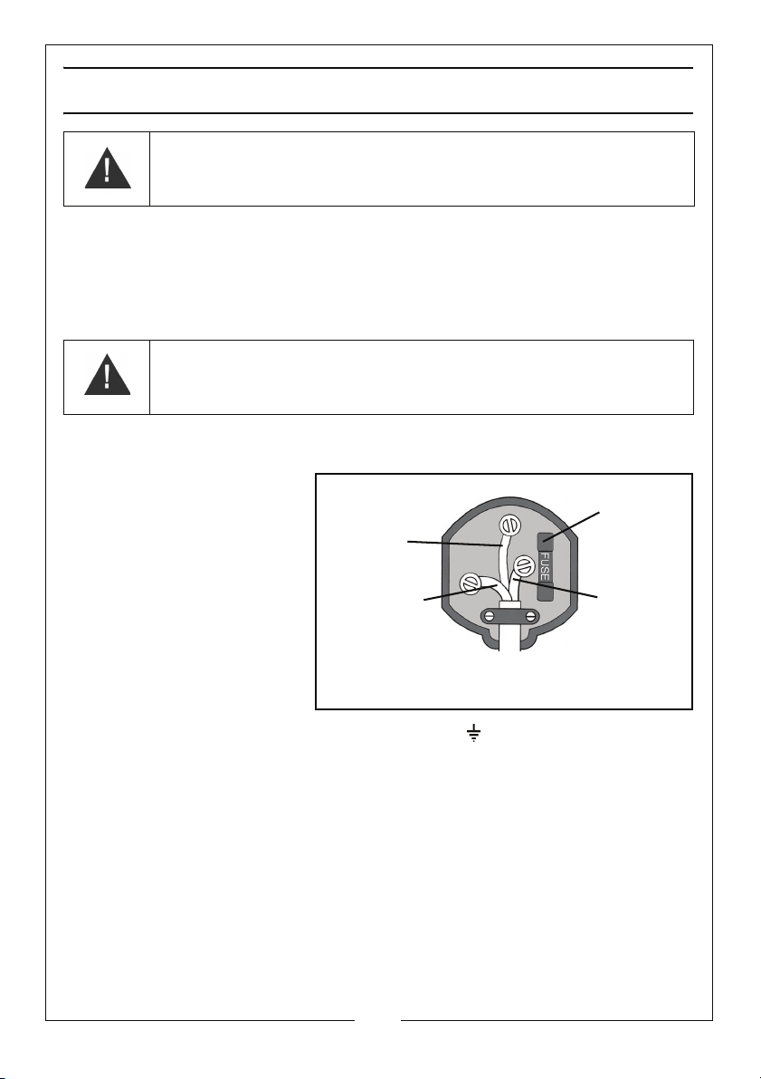
Plug must be BS1363/A approved.
Always fit
Ensure that the outer sheath of
Neutral
(Blue)
Live
(Brown)
Earth
(Green and
a 13 Amp
the cable is firmly held by the clamp
fuse.
Yel low)
WARNING! Read these electrical safety instructions thoroughly
before connecting the product to the mains supply.
Connect the mains lead to a standard, 230 Volt (50Hz) electrical supply through an
approved 13 amp BS 1363 plug, or a suitably fused isolator switch.
If the plug has to be changed because it is not suitable for your socket, or due to
damage, it should be cut off and a replacement fitted, following the wiring instructions
shown below. The old plug must be disposed of safely, as insertion into a mains socket
could cause an electrical hazard.
WARNING! The wires in the power cable of this product are
coloured in accordance with the following code:
Blue = Neutral Brown = Live Yellow and Green = Earth
If the colours of the wires in the power cable of this product do not correspond with the
markings on the terminals of your plug, proceed as follows.
• The wire which is
coloured Blue must be
connected to the
terminal which is marked
N or coloured Black.
• The wire which is
coloured Brown must be
connected to the
terminal which is marked
L or coloured Red.
• The wire which is
coloured Yellow and
Green must be
connected to the terminal which is marked E or or coloured Green.
We strongly recommend that this machine is connected to the mains supply via a
Residual Current Device (RCD)
If in any doubt, consult a qualified electrician. DO NOT attempt any repairs yourself
Parts & Service: 020 8988 7400 / E-mail: [email protected] or [email protected]
4
Page 5
ASSEMBLY
CAUTION: THE COMPRESSOR IS HEAVY, GET ASSISTANCE WHEN LIFTING
OR MOVING THIS COMPRESSOR TO AVOID PERSONAL INJURY.
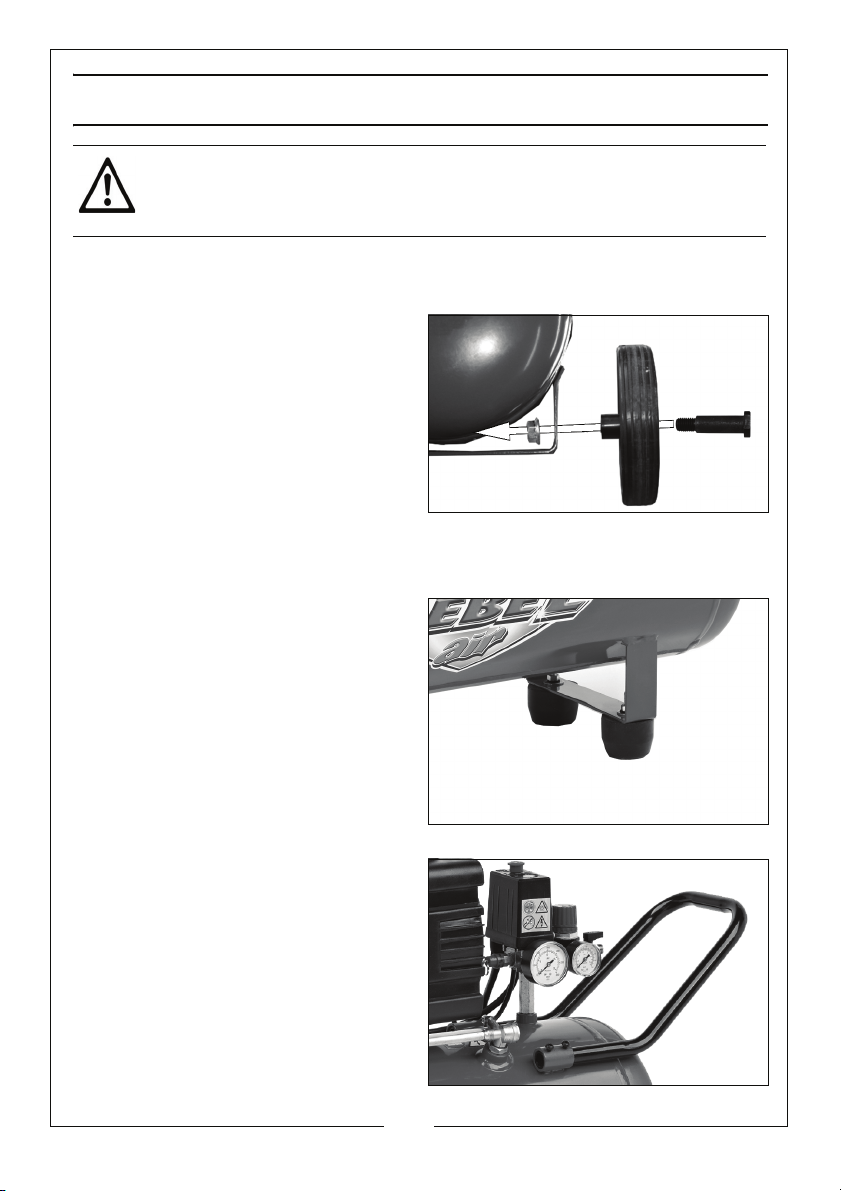
FITTING THE WHEELS
Using the axle and nut, secure the
wheels as shown.
Make sure the wheels are secure
before use.
FITTING THE SUPPORT FEET
Fix the support feet into place as
shown using the fixings supplied.
FITTING THE HANDLE
Slide the handle into the position
shown and secure in place using the
fixings supplied.
5
Parts & Service: 020 8988 7400 / E-mail: [email protected] or [email protected]
Page 6
MOVING THE AIR COMPRESSOR
Before moving the compressor, switch off and disconnect it from the mains
power supply.
• Always use the handle.
• Only move the compressor when it is switched off.
• Do not lift by (or put strain on) fittings, valves or hoses.
• Take care when moving the compressor to avoid damaging the
valves or fittings
BEFORE USE
Before connecting your compressor to the mains supply, check the following:-
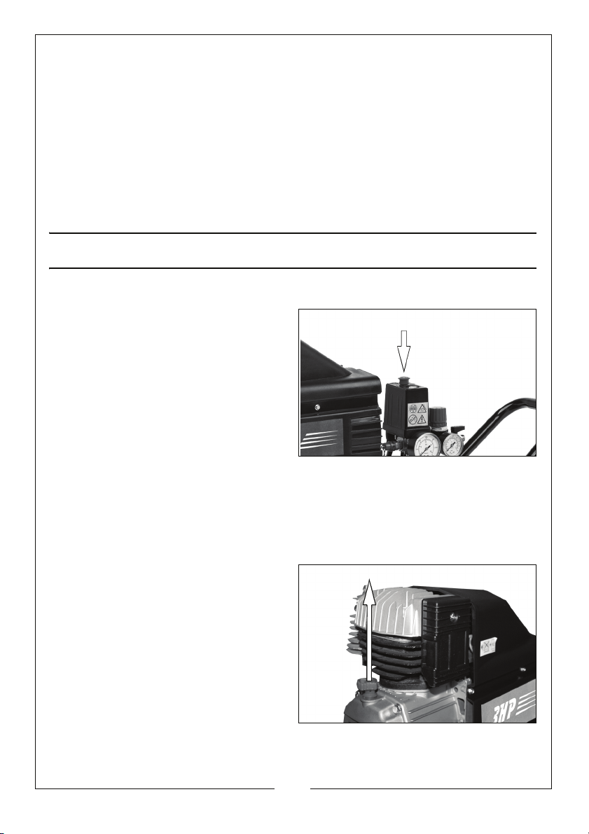
• Make sure that the ON/OFF
switch is in the OFF (pressed
down) position.
• Make sure the compressor is on
level ground.
• Check that the mains voltage is
the same as that shown on the
data label on the compressor.
CHECK THE OIL LEVEL
NOTE: The compressor is supplied without any oil inside, there will also be
a transit plug inserted into the oil reservoir, which must be
removed and the dipstick supplied inserted in its place.
Remove the dipstick from the oil
1.
reservoir.
6
Parts & Service: 020 8988 7400 / E-mail: [email protected] or [email protected]
Page 7
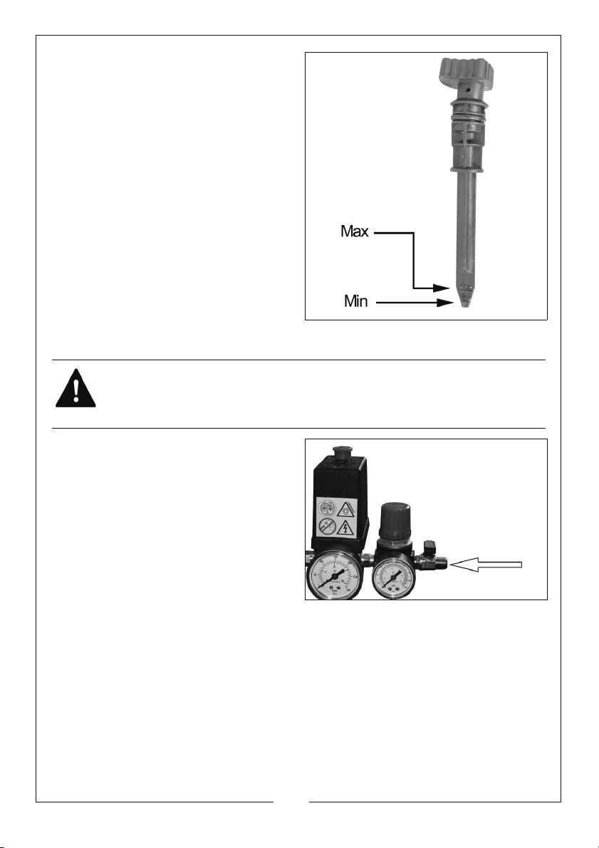
2. Add oil until the oil level is between
the min and max marks on the
ick.
dipst
• Only use SAE40 compressor oil,
available from your Clarke
dealer.
ATTACHING AIR TOOLS
WARNING: BEFORE CONNECTING ANY AIR TOOLS, MAKE SURE YOU
HAVE READ ANY INSTRUCTIONS SUPPLIED WITH THE TOOL, ALSO ENSURE
THAT THE TOOL IS COMPATIBLE WITH THE COMPRESSOR AND HOSE
SPECIFICATIONS.
1. Attach the air hose to the
regulator.
2. Fit the tool to the end of the air
hose.
7
Parts & Service: 020 8988 7400 / E-mail: [email protected] or [email protected]
Page 8
OPERATION
If the compressor has not been used for 24 hours or more, open the drain valve
in the tank to drain any condensate which may have accumulated. See
page 10.
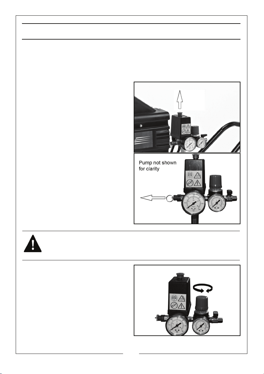
1. Insert the plug into the power so
2.
Lift the On/Off button.
• The compressor will run until the
tank is fully pressurised. It will
then switch off.
• The compressor will start up
again when the pressure in the
tank decreases during use.
3. Make sure the safety valve is
working correctly by pulling on the
ring attached
• Air should be released when the
ring is
released.
• If the valve does not operate as
expected, it must be replaced
by qualified service personnel
before the compressor is used.
.
pulled and stop when
cket and switch on the power.
WARNING: DO NOT REMOVE OR ATTEMPT TO ADJUST THE SAFETY VALVE.
Set the operating pressure you
4.
need using the pressure regulator.
• Clockwise to increase the
pressure.
• Anticlockwise to decrease the
pressure.
8
Parts & Service: 020 8988 7400 / E-mail: [email protected] or [email protected]
Page 9
REMOVING TOOLS FROM THE AIR HOSE
WARNING: ALWAYS SET THE PRESSURE REGULATOR TO ZERO BEFORE
ATTEMPTING TO REMOVE OR REPLACE A TOOL.
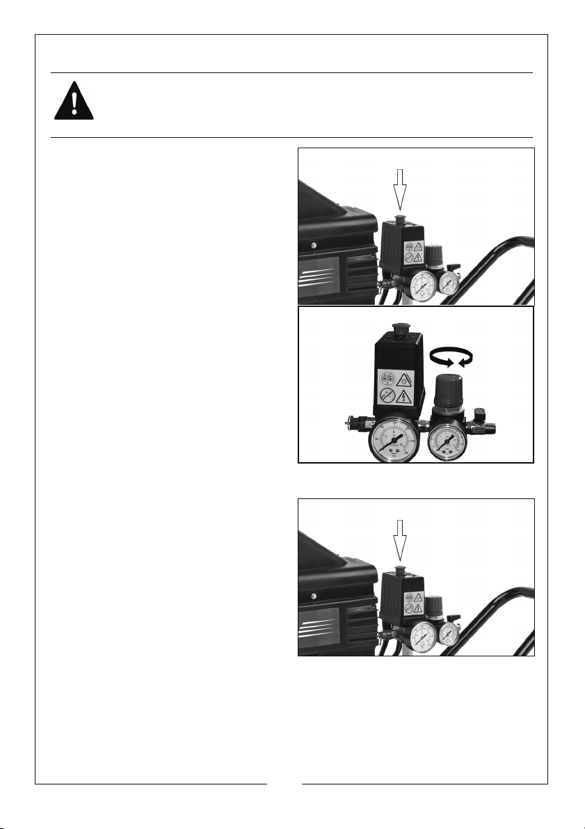
1. Push down on the On/Off button
to stop the compressor.
2. Set the pressure regulator to the
lowest setting (fully anticlockwise).
3. Activate the tool (spray gun etc)
to depr
4. The tool can then be
disconn
essurise the air hose.
ected from the hose.
SHUTTING DOWN THE COMPRESSOR
1. Follow steps 1-3 in “Removing Tools
From The Air Hose” above.
2. Disconnect the compressor from
the mains
• Never leave the compressor
unattended while the tank is
pressurised.
• Always release the pressure
from the tank when not in use or
prior to storage, as described in
the following section.
Parts & Service: 020 8988 7400 / E-mail: [email protected] or [email protected]
supply.
9
Page 10
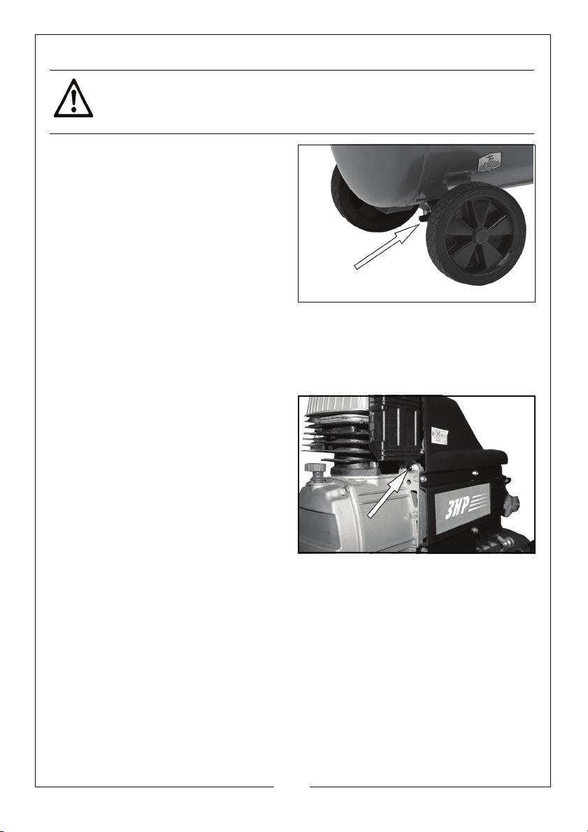
DRAINING THE TANK
CAUTION: YOU MUST DRAIN THE TANK AFTER EACH DAYS USE AND
BEFORE YOU STORE YOUR COMPRESSOR.
1. Turn the compressor off and
disconnect from the power
sup
ply.
• Put a container beneath the
dra
in valve to catch any
condensation.
2. Open the drain valve slowly.
• You will hear a hissing sound as
the tank depr
• Any condensation will drain from the tank.
3. Close the drain valve when the tank has fully drained.
essurises.
RESET BUTTON
This compressor has a thermal
overload device which protects the
motor.
If the motor overheats the thermal
overload device cuts the power, thus
preventing damage to the motor.
If the thermal overload device
activates, wait 5 minutes for the motor
to cool and press the reset button.
If you restart the compressor and the
overload cutout activates again,
• Switch off the compressor.
• Disconnect the compressor from the mains supply.
• Have your compressor checked by a qualified service agent.
10
Parts & Service: 020 8988 7400 / E-mail: [email protected] or [email protected]
Page 11
MAINTENANCE
CHECKING THE OIL LEVEL (DAILY)
Make sure that there is sufficient oil in the oil reservoir (between the min and
max marks on the dipstick, See page 6) and top-up if necessary.
• Only use SAE40 compressor oil, available from your Clarke dealer.
DRAIN THE TANK (DAILY)
When you have finished using the compressor for the day, always open the
drain valve to ensure that any condensate is drained off.
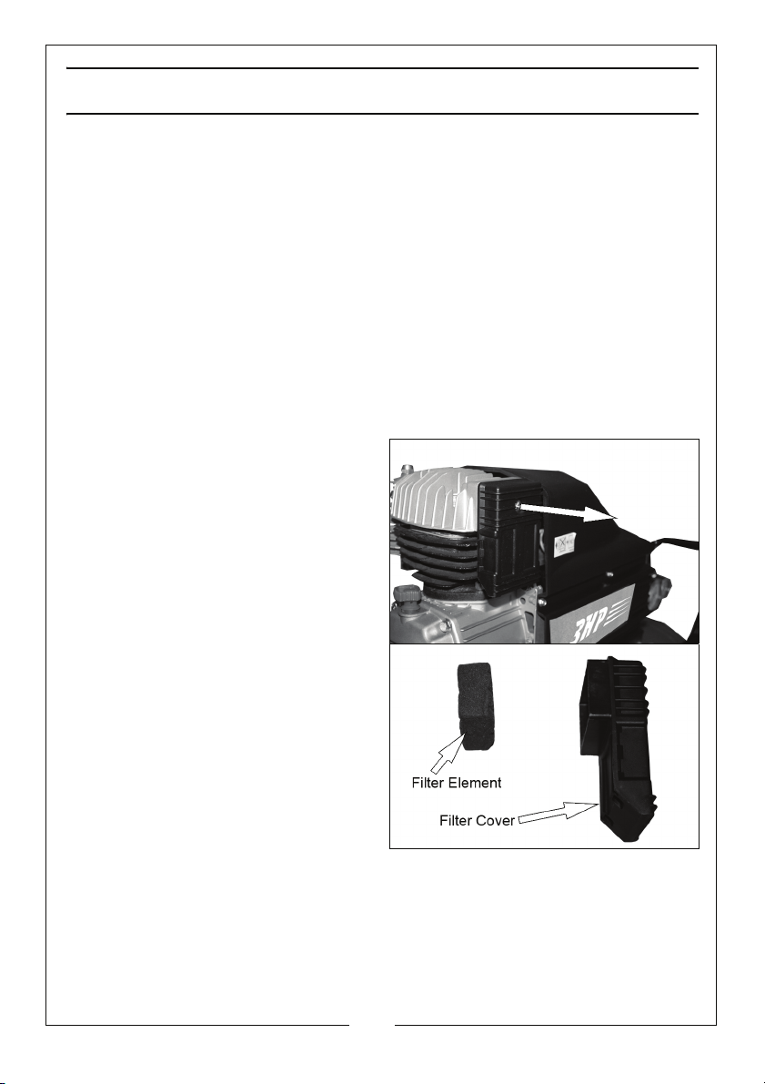
CLEANING THE AIR INTAKE FILTER (MONTHLY)
The air intake filter should be inspected on a monthly basis, and more often in
dusty conditions,
1. Remove the securing screw from
the air filter cover.
2. Remove the air filter cover from
the compr
essor.
3.
Remove the filter element from
the filter cover.
4. Clean the filter element and the
filter cover using a
• If necessary, the sponge filter
may be gently washed in warm
soapy water.
• Rinse and allow the filter to dry
thoroughly before refitting.
5. Ensure that the filter element and filter c
position.
• If the filter is damaged, you should obtain a replacement.
6. Replace the securing screw.
Parts & Service: 020 8988 7400 / E-mail: [email protected] or [email protected]
soft brush.
over are replaced in their original
11
Page 12
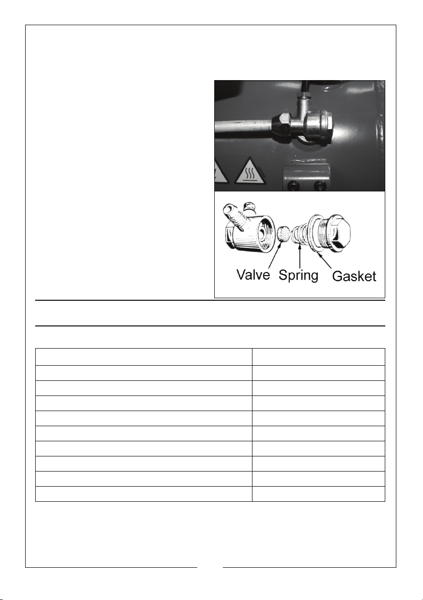
CHECK THE NON RETURN VALVE (EVERY 6 MONTHS)
If the tank pressure decreases for no apparent reason, it is possible that the
non-return valve is leaking. To check the valve:
1. Make sure the tank is not under
pressure and the machine
itched OFF.
sw
2. Examine the non-return valve,
a
nd replace the gasket and valve
if necessary.
SPECIFICATIONS
Rebel 55
Max.Pressure 10 Bar
Vo lt ag e 230V @ 50HZ
Air Displacement 10 CFM
Receiver Capacity 50 L
Fuse Rating 13 A
Dimensions (L x W x H) mm 870 x 350 x 700
Guaranteed Sound Power Level 97 dB(A)
Weight 37 kg
Compressor Oil SAE 30
Please note that the details and specifications co
going to print. We reserve the right to change specifications at any time without prior
notice.
Parts & Service: 020 8988 7400 / E-mail: [email protected] or [email protected]
ntained herein, are correct at the time of
12
Page 13
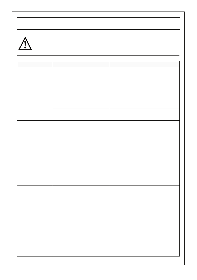
TROUBLESHOOTING
CAUTION: DO NOT ATTEMPT ANY REPAIR OR ADJUSTMENT IF YOU ARE
UNCERTAIN AS TO HOW IT SHOULD BE DONE. IF YOU HAVE ANY QUERIES,
CONTACT YOUR CLARKE DEALER.
PROBLEM PROBABLE CAUSE REMEDY
The compressor
has stopped and
does not start
The compressor
s not reach
doe
the set pressure
and overheats
easily.
Compressor does
start.
not
Air leaking from
e pressure
th
switch valve
when the
compressor is not
running.
Air pressure from
egulator will
the r
not adjust.
The compressor is
very noisy and
makes a metallic
knocking sound.
Bad electrical connections. 1. Check electrical connections.
.
Overload cutout switch has
d.
trippe
Motor windings burnt out. 1. Contact your Clarke dealer for
Compressor head gasket
own or valve broken.
bl
The tank has already fully
pressurised.
Faulty non-return valve. 1. Drain receiver completely of
The diaphragm within the
regulator body is broken.
Compressor damaged and
eds overhaul.
ne
2. Clean and tighten as
ne
1. Switch off and wait approx 5
minutes.
2. Press the reset button and
sw
a replacement
1. Wait for the compressor to
cool down,
2. Remove the cylinder head.
3. Replace any broken
co
4. Carefully clean all sealing
sur
If in doubt contact your Clarke
dealer
1. Open drain valve to expel air.
Compressor should start again
when pressure reduces.
air
2. Remove the valve end plug,
3. Carefully clean the valve seat
and
4. Reassemble.
1. Replace regulator
1. Return the machine to your
nearest service agent.
cessary.
itch on again.
motor.
mponents.
faces before reassembling.
.
.
the gasket
13
Parts & Service: 020 8988 7400 / E-mail: [email protected] or [email protected]
Page 14
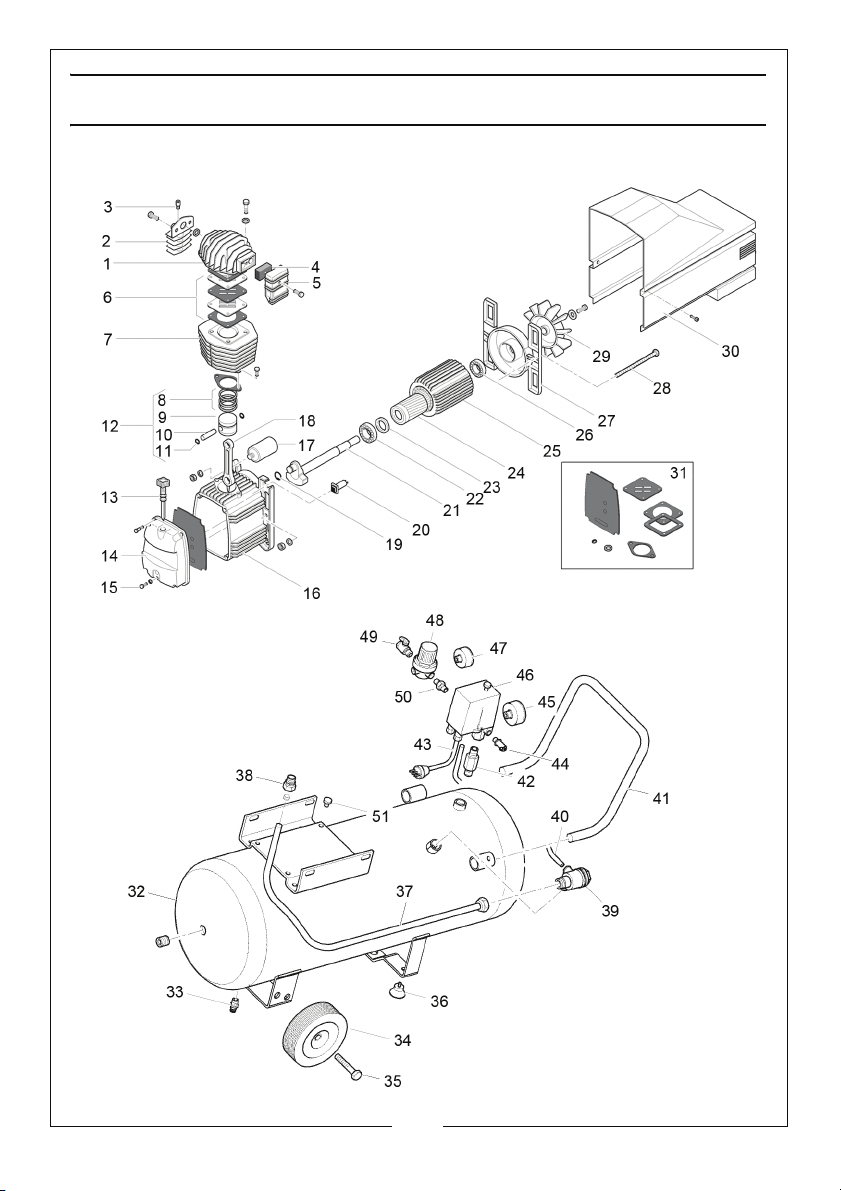
Page 15
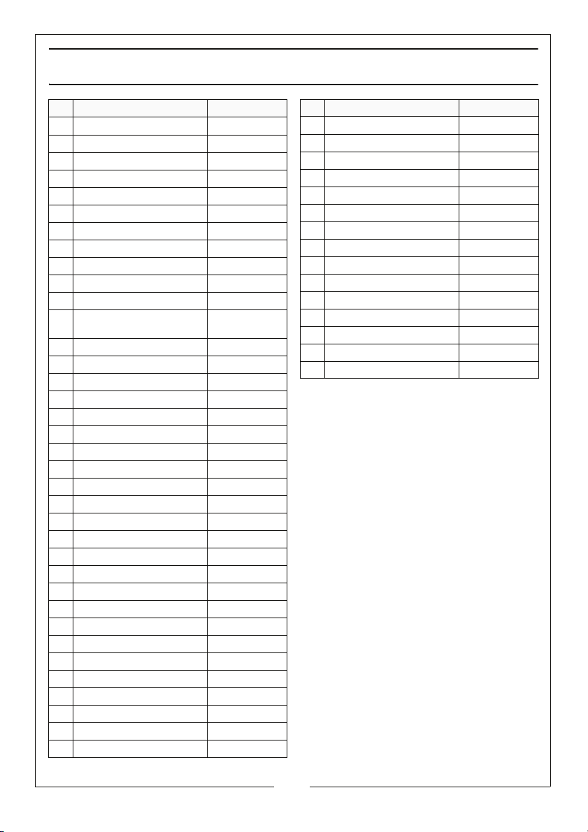
PARTS LIST
NO DESCRIPTION PAR T N O
1 HEAD FN116091003
2 COOLING FINS FN116091024
3 DISCHARGE VALVE FN011158000
4 FILTER ELEMENT FN116091018
5 FILTER BODY FN116091009
6 VA LVE P L ATE SE T FN116091040
7 CYLINDER FN116002003
8 PISTON RINGS FN213115002
9 PISTON FN113115026
10 PISTON PIN FN113115025
11 CIRCLIP FN015002000
12 COMPLETE PISTON
SSEMBLY
A
13 OIL DIPSTICK FN012043000
14 FRONT COVER FN016091002
15 SCREW FN014013024
16 CRANCKCASE FN116091001
17 CAPACITOR FN116002004
18 CON. ROD FN009200026
19 CIRCLIP FN015005000
20 OVERLOAD CUT-OUT FN008399000
21 CRANKSHAFT FN116091010
22 BEARING FN033027000
23 SEAL FN010029000
24 ROTOR FN034110000
25 STATOR FN416107605
26 BEARING FN033118000
27 BACK COVER FN116011002
28 SCREW M6X150 FN116042020
29 FAN FN116091005
30 SHROUD FN116091007
31 GASKETS KIT FN216AG0001
32 TANK 50L FN9413303053
33 DRAIN VALVE FN9047051
34 WHEEL FN9042045
35 WHEEL AXLE FN9416613
36 RUBBER FOOT FN9038197
FN413115026
NO DESCRIPTION PA RT NO
37 CONNECTING PIPE FN9043285
38 connector FN9050508
39 NON RETURN VALVE FN9048025
40 RILSAN PIPE FN9270006
41 HANDLE FN9083711
42 CONNECTOR FN9050547
43 POWER CABLE FN9065683
44 SAFETY VALVE FN9049019
GAUGE FN9052013
45
46 PRESSUSRE SWITCH FN9063084
47 GAUGE FN9052092
48 PRESSURE REGULATOR FN9051116
49 CONNECTION TAP FN9047077
50 CONNECTOR FN9050373
51 VIBRATION DAMPER
FN9038450
15
Parts & Service: 020 8988 7400 / E-mail: [email protected] or [email protected]
Page 16
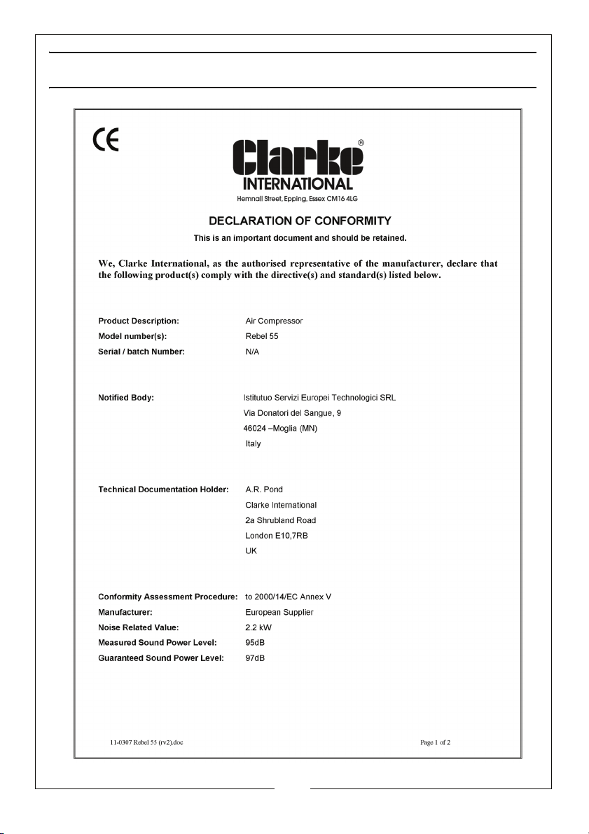
DECLARATION OF CONFORMITY
16
Parts & Service: 020 8988 7400 / E-mail: [email protected] or [email protected]
Page 17
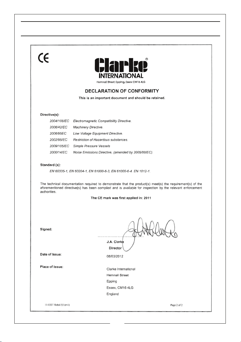
DECLARATION OF CONFORMITY
17
Parts & Service: 020 8988 7400 / E-mail: [email protected] or [email protected]
Page 18
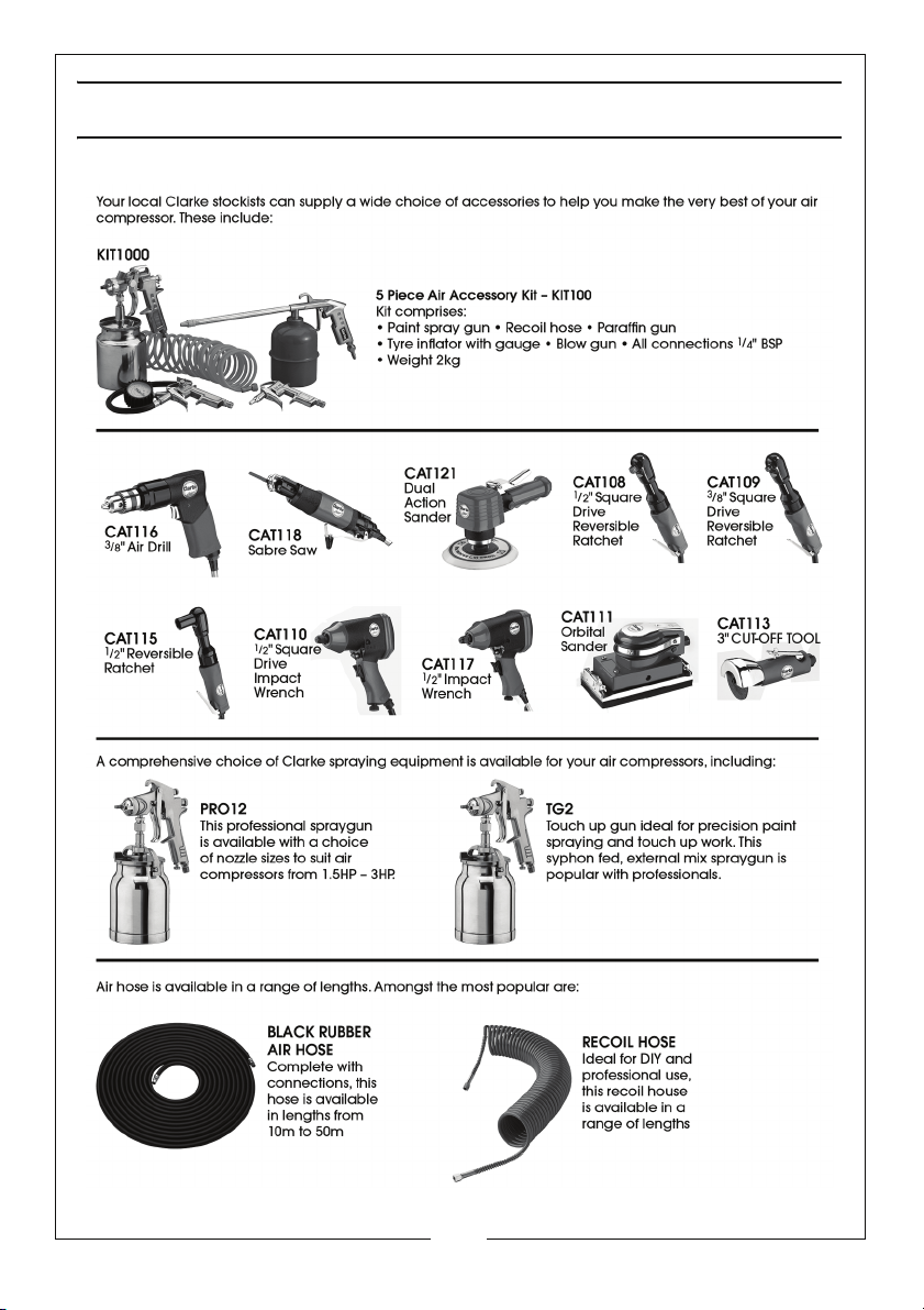
POPULAR ACCESSORIES
18
Parts & Service: 020 8988 7400 / E-mail: [email protected] or [email protected]
Page 19

Page 20
 Loading...