

Page 1
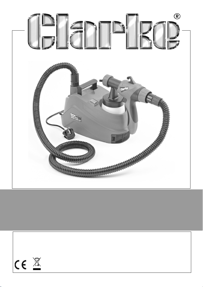
HVLP ELECTRIC SPRAY STATION
MODEL NO: APK900
PART NO: 2310060
OPERATION & MAINTENANCE
INSTRUCTIONS
ORIGINAL INSTRUCTIONS GC1120 - ISS 4
Page 2
INTRODUCTION
Thank you for purchasing this CLARKE HVLP (high velocity/low pressure)
Electric Spray Station. Before attempting to use this product, please read this
manual thoroughly and follow the instructions carefully. In doing so you will
ensure the safety of yourself and that of others around you, and you can look
forward to your purchase giving you long and satisfactory service.
IMPORTANT
Please read all of the safety and operating instructions carefully before using
this product. Please pay particular attention to all sections of these instructions
that display warning symbols and notices.
WARNING: THIS SYMBOL IS USED THROUGHOUT THE INSTRUCTIONS
WHENEVER THERE IS A RISK OF PERSONAL INJURY. ENSURE THAT
THESE WARNINGS ARE READ AND UNDERSTOOD AT ALL TIMES.
GUARANTEE
This product is guaranteed against faulty manufacture for a period of 12
months from the date of purchase. Please keep your receipt which will be
required as proof of purchase.
This guarantee is invalid if the product is found to have been abused or
tampered with in any way, or not used for the purpose for which it was
intended.
Faulty goods should be returned to their place of purchase, no product can
be returned to us without prior permission.
This guarantee does not effect your statutory rights.
2
Parts & Service: 020 8988 7400 / E-mail: [email protected] or [email protected]
Page 3

GENERAL SAFETY RULES
WARNING: WHEN USING ELECTRIC TOOLS, BASIC SAFETY PRECAUTIONS
SHOULD ALWAYS BE FOLLOWED TO REDUCE THE RISK OF FIRE, ELECTRIC
SHOCK AND PERSONAL INJURY INCLUDING THE FOLLOWING. READ ALL
THESE INSTRUCTIONS BEFORE ATTEMPTING TO OPERATE THIS PRODUCT
AND SAVE THESE INSTRUCTIONS FOR FUTURE REFERENCE.
GENERAL SAFETY IN THE WORKPLACE
1. Always ensure that air can circulate around the machine and that the air
vents are unobstructed.
2. Always keep work area clean & tidy. Cluttered work areas and benches
invite accidents.
3. Never over-reach. Keep proper footing and balance at all times.
4. Never store equipment in a wet/damp environment or expose to rain.
5. Keep other persons away. Do not let persons, especially children, not
involved in the work, touch the tool or extension cable and keep them
away from the work area.
6. Never operate a machine when under the influence of alcohol, drugs or
medication.
7. Always ensure the workplace is well lit. Ensure that lighting is placed so that
you will not be working in your own shadow.
8. Do not use tools in the presence of flammable liquids or gasses.
9. Stay alert, watch what you are doing, use common sense and do not
operate the tool when you are tired.
CARE OF POWER TOOLS
1. Read this manual carefully. Learn the machines applications and
limitations, as well as the specific potential hazards peculiar to it.
2. Always keep guards in place and in working order. A guard or other part
that is damaged should be properly repaired or replaced by an authorised
service centre, unless otherwise indicated in this instruction manual.
3. Remove any adjusting keys or wrenches before starting. Form the habit of
checking to ensure that keys, wrenches and tools are removed from the
machine.
4. Always disconnect the machine from the power supply before carrying out
any servicing or changing of accessories.
3
Parts & Service: 020 8988 7400 / E-mail: [email protected] or [email protected]
Page 4

5. Before further use of the tool, it should be carefully checked to determine
that it will operate properly and perform its intended function. Check for
alignment of moving parts, binding of moving parts, breakage of parts,
mounting or other condition that may affect its operation.
6. Have defective switches repaired by an authorised service centre. Do not
use a tool if the switch does not turn it on and off.
7. Always check for any damage or any condition that could affect the
operation of the machine. Damaged parts should be properly repaired.
8. Never remove the cover panel unless the machine is disconnected from
the power supply, and never use the machine with cover panels removed.
9. Have your tool repaired by a qualified person. This tool complies with the
relevant safety rules. Repairs should only be carried out by qualified
persons using original spare parts, otherwise this may result in considerable
danger to the user.
10. Never use this product for any other purpose than that described in this
booklet.
11. Never abuse the power cable by yanking the cable to disconnect it from
the socket. Keep the cable away from heat, oil or sharp edges.
12. Guard against electric shock. Avoid body contact with earthed or
grounded surfaces.
13. If the tool should be used outdoors, use only extension cables intended for
outdoor use and marked accordingly.
14. Avoid accidental starting by making sure the power switch is off before
plugging in the power cable.
4
Parts & Service: 020 8988 7400 / E-mail: [email protected] or [email protected]
Page 5
ELECTRICAL CONNECTIONS
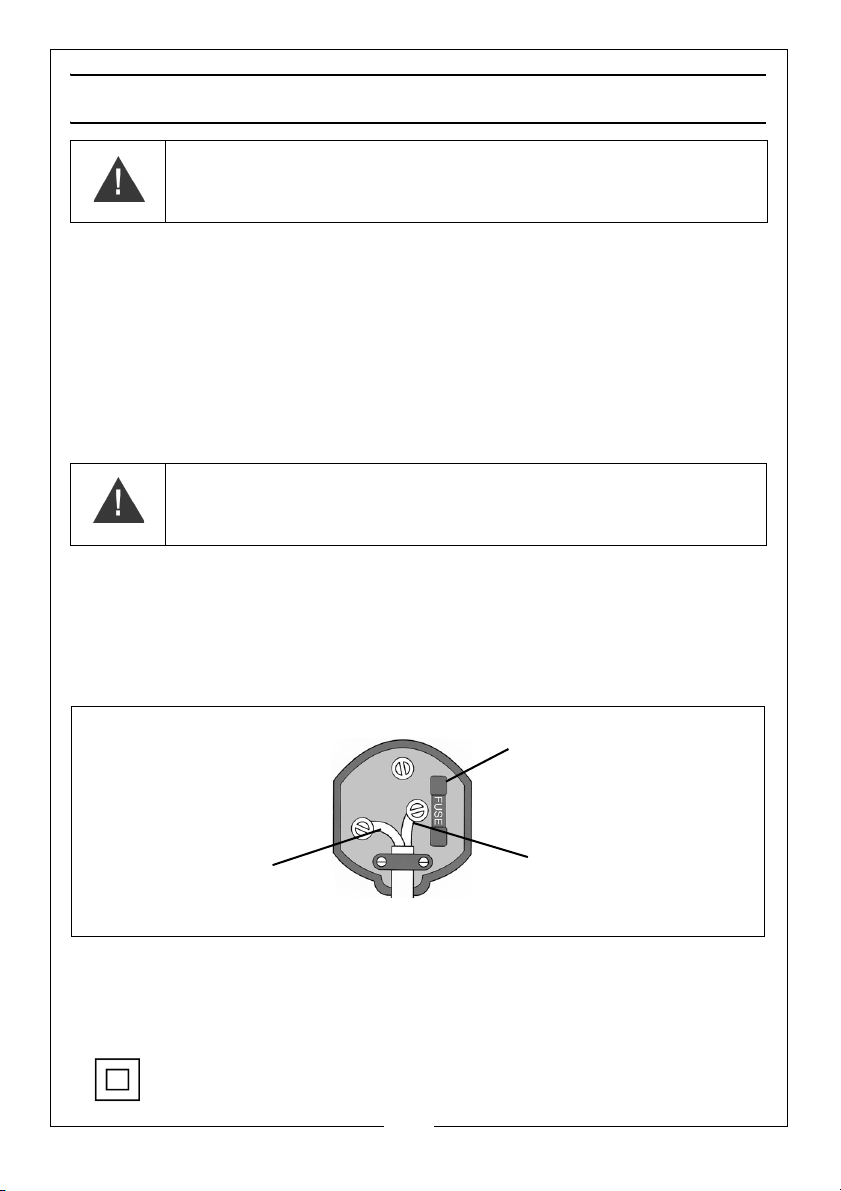
Plug must be BS1363/A approved.
Always fit a 5 Amp fuse.
Ensure that the outer sheath of the cable is firmly held by the clamp
Neutral
(Blue)
Live
(Brown)
WARNING: READ THESE ELECTRICAL SAFETY INSTRUCTIONS
THOROUGHLY BEFORE CONNECTING THE PRODUCT TO THE MAINS
SUPPLY.
Before switching the product on, make sure that the voltage of your electricity supply is
the same as that indicated on the rating plate. This product is designed to operate on
230VAC 50Hz. Connecting it to any other power source may cause damage.
This product may be fitted with a non-rewireable plug. If it is necessary to change the
fuse in the plug, the fuse cover must be refitted. If the fuse cover becomes lost or
damaged, the plug must not be used until a suitable replacement is obtained.
If the plug has to be changed because it is not suitable for your socket, or due to
damage, it should be cut off and a replacement fitted, following the wiring instructions
shown below. The old plug must be disposed of safely, as insertion into a mains socket
could cause an electrical hazard.
WARNING: THE WIRES IN THE POWER CABLE OF THIS PRODUCT ARE
COLOURED IN ACCORDANCE WITH THE FOLLOWING CODE:
BLUE = NEUTRAL BROWN = LIVE
If the colours of the wires in the power cable of this product do not correspond
with the markings on the terminals of your plug, proceed as follows.
• The wire which is coloured Blue must be connected to the terminal
which is marked N or coloured Black.
• The wire which is coloured Brown must be connected to the terminal
which is marked L or coloured Red.
We strongly recommend that this machine is connected to the mains supply
via a Residual Current Device (RCD)
If in any doubt, consult a qualified electrician. DO NOT attempt any repairs
yourself.
This symbol indicates that this is a Class II product and does not
require an earth connection.
Parts & Service: 020 8988 7400 / E-mail: [email protected] or [email protected]
5
Page 6
OVERVIEW
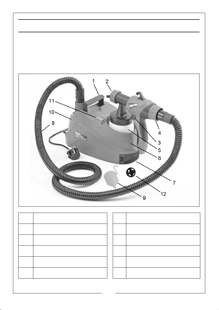
The High Volume/Low Pressure (HVLP) spray gun reduces the spray mist associated with compressed air spraying and therefore both reduces paint loss and
masking requirements. The gun may be used with various spray mediums, including varnishes, wood preservatives, masonry paints, enamel paints, and oil and
water based paints.
.
1 Carrying Handle 7 Air Filter Cover
2 Spray Nozzle Assembly 8 Connecting Hose
3 Trigger 9 Viscosity Cup
4 Trigger Stop Regulator 10 Base Unit
5 Paint Container 11 On/Off Switch
6 Spray Gun Holder 12 Spare Spray Nozzle (2.6 mm)
6
Parts & Service: 020 8988 7400 / E-mail: [email protected] or [email protected]
Page 7
OPERATION
GENERAL PREPARATION
Do not use textured wall paints or coatings as they are likely to block the
nozzle. To obtain the best results, it is important that you prepare the surface to
be sprayed and thin the paint to the correct viscosity before you operate your
spray gun. Always ensure that the surfaces to be sprayed are free from dust,
dirt and grease. Make sure that you have masked the areas that should not
be sprayed, using a good quality masking tape.
Paint to be sprayed should be thoroughly mixed and free from lumps or other
particles. Many substances can be sprayed with this spray gun, but always
check the manufacturers recommendations before purchasing your paint.
PAINT PREPARATION
CAUTION: ALWAYS REMEMBER TO DISCONNECT FROM THE MAINS
SUPPLY BEFORE FILLING THE PAINT CONTAINER WITH SPRAYABLE
MATERIALS
Most paints are supplied ready for brush application and will need to be
thinned before they are suitable to be sprayed. Follow the manufacturers
advice on thinning the paint when used with a spray gun. Using the viscosity
cup will help you to determine the correct viscosity of paint to be used.
To do this, fill the cup to the brim with the paint and measure the amount of
time it takes for the cup to empty back into the can. The table below shows
recommended times for different materials.
Material Runout Time
Emulsion paint 18 - 22 seconds
Thinner-soluble primers 25 - 40 seconds
Thinner-soluble varnishes 15 - 40 seconds
Water-soluble primers 25 - 40 seconds
Water-soluble varnishes 20 - 35 seconds
Automotive spray paint 20 - 35 seconds
Wood preservatives No thinning required
Wood stains No thinning required
7
Parts & Service: 020 8988 7400 / E-mail: [email protected] or [email protected]
Page 8
If the paint takes longer than the recommended time to empty, further
thinning is required. Mix in a small quantity of the appropriate thinner and
repeat the viscosity test until the correct thickness is achieved. Some
sprayable materials contain particles and lumps which should be strained
before filling the paint container.
START-UP
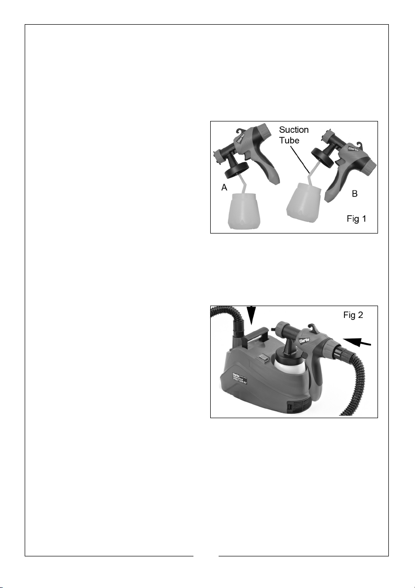
1. Unscrew the container from the
spray gun and align the suction
tube to suit the angle of spraying.
• When spraying horizontal
surfaces or pointing the gun
downwards, turn the suction
tube forward (A). If spraying
objects at high level, turn the
suction tube back towards you
(B) as shown in Fig 1.
2. Fill the container with prepared paint and screw the container onto the
spray gun. Place the spray gun in the holder of the machine base until
ready to start spraying.
• Always place the spray gun base assembly on a clean surface to
avoid sucking in dust etc through the air filter.
3. Connect the air hose to both the
base and the spray gun as shown
in Fig 2.
4. Connect the spray gun to the
mains supply.
ADJUSTMENTS
SPRAY PATTERN
Adjust the spray gun by rotating the
nozzle and setting the tabs on the air
cap as shown. Three different spray settings can be chosen, depending on
the application and target object.
A) Flat, narrow jet (for horizontal surfaces)
B) Tall, narrow jet (for vertical surfaces)
C) Circular jet (for corners, edges and hard to reach areas
8
Parts & Service: 020 8988 7400 / E-mail: [email protected] or [email protected]
Page 9
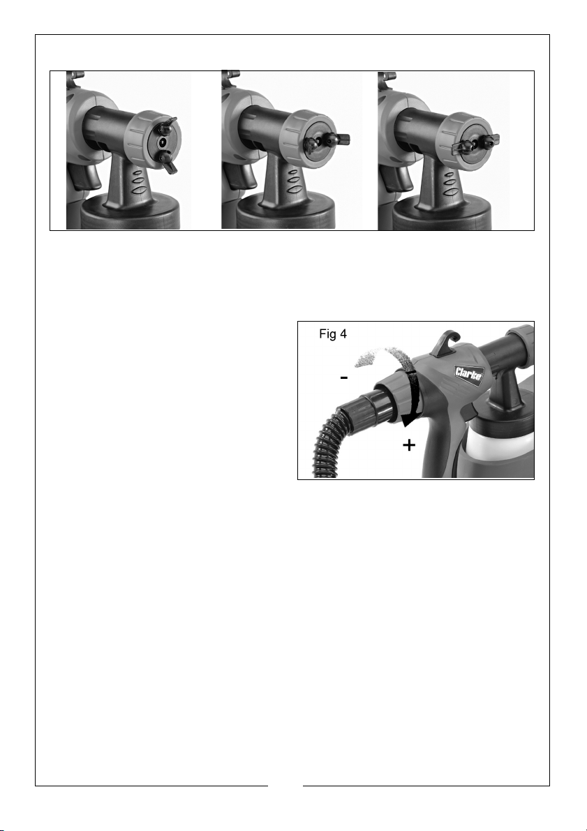
A) horizontal flat jet B) Vertical Jet C) Tabs back Fig 3
• Note that both tabs must be adjusted as a pair.
SPRAY VOLUME
1. In order to achieve consistent and
repeatable spray output, adjust
the spray volume by turning the
trigger stop regulator on the rear
of the spray gun as shown in Fig 4.
• Turn as shown; + to increase the
volume of material and - to
reduce.
• Adjustment of the regulator will
also affect the pattern. A poor
spray pattern will concentrate the paint in the centre of the spray
and give a blotchy finish. A good spray pattern will give even
distribution of paint across the pattern.
2. Aim the spray gun at a piece of scrap material and operate the trigger
until paint is spraying. Adjust the regulator until the required volume of paint
is spraying.
SPRAYING TECHNIQUE
The quality of the finished work depends on the smoothness and cleanliness of
the surface to be sprayed. Therefore the surface should be carefully prepared
and kept free from dust. Carefully mask all areas not to be painted and cover
all surrounding areas.
It is advisable to test the spray gun on cardboard or a similar surface to find
the correct setting. Start spraying outside the actual target area and pass
smoothly across the target without stoppages.
9
Parts & Service: 020 8988 7400 / E-mail: [email protected] or [email protected]
Page 10
Control the speed of movement of the spray gun evenly. A fast speed of
movement over the surface will give a thin coat and a slow speed will give a
heavy coat.
Apply one coat at a time. If a further coat is required, make sure you observe
the manufacturer’s drying time recommendations before applying a second
coat. When spraying small areas, keep the regulator on a low setting. This will
avoid using too much paint and prevent overspray.
Where possible, avoid stopping and starting when spraying an object. This can
lead to too much, or not enough paint being applied to local areas. Do not tilt
the spray gun at more than 45 deg.
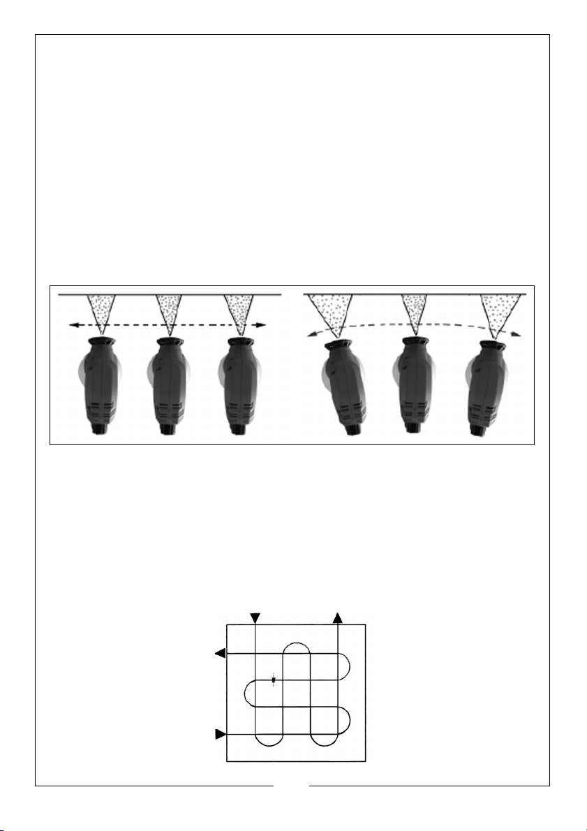
Hold the spray gun at an even distance from the target as shown in Fig 5 and
avoid an uneven movement.
RIGHT WRONG Fig 5
To obtain the best results, keep your spray gun level and parallel to the surface
at all times. Keep the nozzle 25 - 30 cm from the surface and spray evenly from
side to side or up and down. Do not spray at an angle as this will lead to paint
runs on the surface. Use smooth and even strokes. When spraying large areas,
using a cris-cross pattern as shown in Fig 6.
10
Parts & Service: 020 8988 7400 / E-mail: [email protected] or [email protected]
Page 11
CLEANING AND MAINTENANCE
CLEANING
Continuous satisfactory operation depends upon proper care and regular
cleaning. It is essential that the spray gun is cleaned thoroughly after every
use. Failure to clean it will almost certainly result in blockages and it may not
operate correctly when you next come to use it. The following action must be
taken after every use.
1. Allow the remaining paint to flow back into the paint container. Empty any
remaining material from the container.
2. Clean the paint container and suction tube thoroughly with a brush.
3. Pour some thinners or water (as applicable) into the container and screw
back on. Turn the spray gun back on and spray into a container or cloth.
Repeat until only clean thinners is coming out of the nozzle.
4. Turn the spray gun off and empty the paint container completely of any
remaining thinners. Always ensure the container sealing disc is free of paint
residue and check for any damage.
5. Clean the outside of the spray gun and container with a cloth soaked in
thinners or water (as applicable).
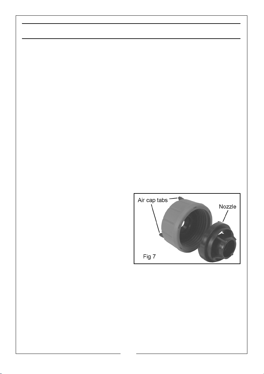
6. Unscrew the union nut and
remove the air cap and nozzle.
Clean the air cap and nozzle with
a brush and thinners or water.
• Never clean the nozzle or air
holes with sharp metal objects.
11
Parts & Service: 020 8988 7400 / E-mail: [email protected] or [email protected]
Page 12
MAINTENANCE
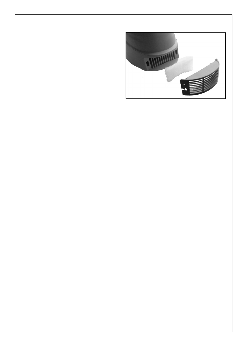
1. Release the cover from the base
unit by pinching the side clips
together and lifting the cover off.
2. Inspect the condition of the air
filter.
3. The filter can be washed in soapy
water or it should be replaced if
badly fouled.
4. Replace the filter and the cover.
IMPORTANT: Never operate without the air filter;- dirt could be sucked in
and interfere with the function of the spray gun.
Check the power cable to ensure it is sound and free from cracks, bare wires
etc.
The nozzle parts may wear with long term use, depending on the abrasiveness
of the materials being sprayed. More abrasive materials, such as emulsions, will
cause faster wear.
A worn nozzle may eventually develop a larger hole and scratches on the
surface, which will cause a poor spray pattern. Replacements are available
from your dealer or the Clarke International Parts Department.
STORAGE
For long term storage, always store in a well ventilated area and keep the
product dry and dust free.
ENVIRONMENTAL PROTECTION
If disposing of this product or any damaged components, do not dispose of
with general waste. This product contain valuable raw materials and must be
disposed of according to the laws governing Waste Electrical and Electronic
equipment and should be taken to your local civic amenity site for recycling.
Through purchase of this product, the customer is taking on the obligation to
deal with the WEEE in accordance with the WEEE regulations in relation to the
treatment, recycling & recovery and environmentally sound disposal of the
WEEE.
In effect, this means that this product must not be disposed of with general
household waste. It must be disposed of according to the laws governing
Waste Electrical and Electronic Equipment (WEEE) at a recognised disposal
facility.
12
Parts & Service: 020 8988 7400 / E-mail: [email protected] or [email protected]
Page 13
TROUBLESHOOTING
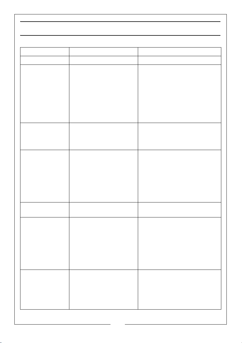
PROBLEM PROBABLE CAUSE SOLUTION
No spray or sound No power. Check power supply.
Motor hums but
does not spray or
spray is irregular
Atomisation is
poor.
Overpainting Gun not clean, resulting in
Motor louder than
normal.
Operating sound
not normal.
Orange peel or
excessive fogging
Pick up pipe in the wrong
position.
Blocked pick-up pipe.
Blocked nozzle.
Blocked air filter.
Paint volume needs
adjustment.
Paint volume adjustment
incorrect.
Paint too thick.
valve sticking.
Too much paint.
.
Viscosity too low.
Gun not clean. Dismantle spray gun and clean
Poor output adjustment
Not enough paint in container resulting in air being
sucked in.
Paint not correctly diluted
or not passing pickup
pipe completely.
Incorrect solvent used.
Spray gun too far from
surface.
Paint too thick.
Adjust pick-u p pipe.
Clean with thinners.
Clean nozzle.
Wash out, dry and re-fit.
Adjust regulator.
Adjust regulator.
Check viscosity of paint.
Dismantle spray gun and clean
out with thinners.
Adjust the volume regulator to
reduce spraying. Apply two thin
coats of paint.
Check viscosity using the
viscosity cup.
with thinnners.
Adjust regulator.
Re-fill container with paint.
Check pick-up pipe and paint
viscosity.
Use different solvent.
Hold spray gun closer to the target.
Thin the paint. Test velocity
using the viscosity cup.
13
Parts & Service: 020 8988 7400 / E-mail: [email protected] or [email protected]
Page 14
SPECIFICATION
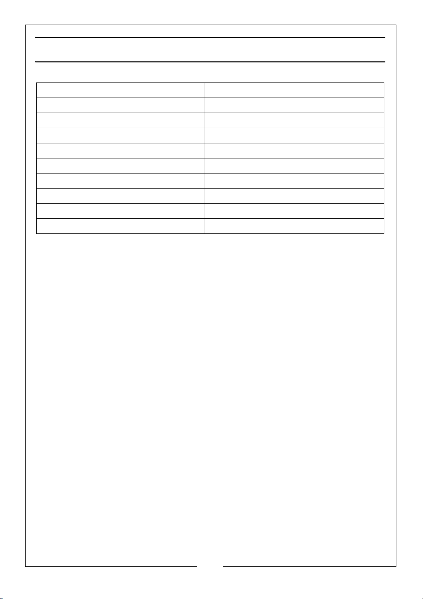
Dimensions (L x W x H) 340 x 170 x 200 mm
Product Weight 3.2 kg
Container Capacity 700 ml
Hose Length 1.9 m
Maximum Nozzle Flow Rate 900 ml/min
Rated Input Power 900 W
Voltage 220-240 V/50 Hz
Insulation Class Class II
Sound Pressure Level 83 dB LpA
Sound Power Level 96 dB LwA
Please note that details and specifications contained herein, are correct at
the time of going to print. However, CLARKE International reserve the right to
change specifications at any time without prior notice.
14
Parts & Service: 020 8988 7400 / E-mail: [email protected] or [email protected]
Page 15
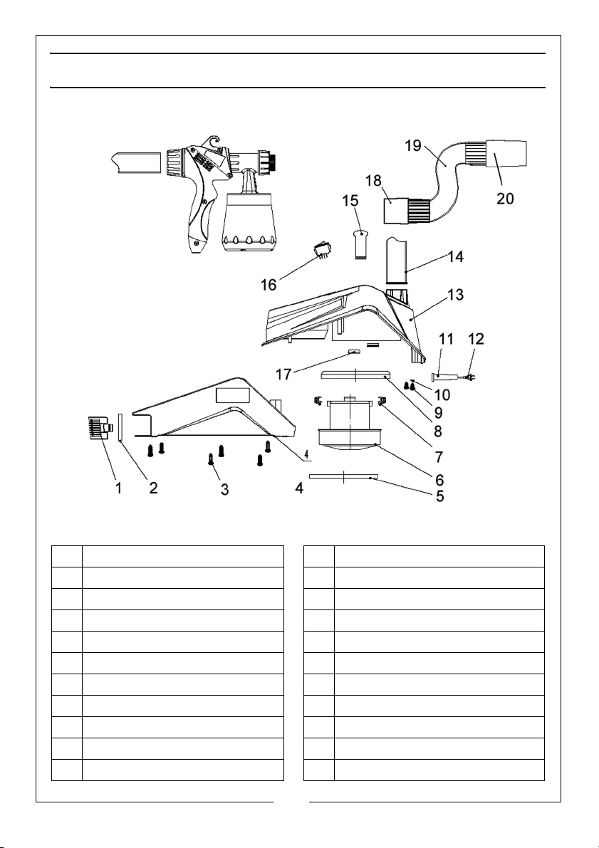
COMPONENT PARTS - BASE ASSEMBLY
No Description No Description
1 Air Filter Cover 11 Cable Sleeve
2 Air Filter 12 Power Cable
3 Self-tapping Screw 13 Upper Housing
4 Base Housing 14 Connecting Hose
5 Heat Insulation Ring 15 Handle
6 Motor 16 On/Off Switch
7 Connector 17 Rubber Sealing Ring
8 Motor Sealing Ring 18 Short Tube Connector
9 Self-tapping Screw 2.9 x 9.5 19 Bellows
10 Cable Clip 20 Long Tube Connector
15
Parts & Service: 020 8988 7400 / E-mail: [email protected] or [email protected]
Page 16
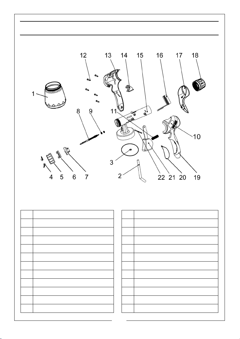
COMPONENT PARTS - SPRAY GUN
No Description No Description
1 Paint Container 12 Self-tapping Screw 4 x 16
2 Suction Tube 13 Housing (R/H)
3 Container Sealing Disc 14 Hook
4 Adjusting Tab 15 Gun Body
5 Union Nut 16 Trigger Stopper
6 Adjsutable Air Cap 17 Rear Cover
7 Fixed Nozzle (2.6 mm) 18 Regulator Knob
8 Valve Stem 19 Housing (L/H)
9 O-Ring 20 Front Cover Pad
10 Nameplate Sticker 21 Trigger
11 Valve Stem Spring 22 Dowel Rod
16
Parts & Service: 020 8988 7400 / E-mail: [email protected] or [email protected]
Page 17
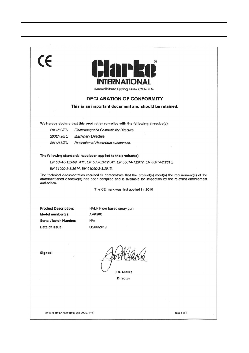
DECLARATION OF CONFORMITY
17
Parts & Service: 020 8988 7400 / E-mail: [email protected] or [email protected]
Page 18

NOTES
_____________________________________________________________________________
_____________________________________________________________________________
_____________________________________________________________________________
_____________________________________________________________________________
_____________________________________________________________________________
_____________________________________________________________________________
_____________________________________________________________________________
_____________________________________________________________________________
_____________________________________________________________________________
_____________________________________________________________________________
_____________________________________________________________________________
_____________________________________________________________________________
_____________________________________________________________________________
_____________________________________________________________________________
18
Parts & Service: 020 8988 7400 / E-mail: [email protected] or [email protected]
Page 19

NOTES
_____________________________________________________________________________
_____________________________________________________________________________
_____________________________________________________________________________
_____________________________________________________________________________
_____________________________________________________________________________
_____________________________________________________________________________
_____________________________________________________________________________
_____________________________________________________________________________
_____________________________________________________________________________
_____________________________________________________________________________
_____________________________________________________________________________
_____________________________________________________________________________
_____________________________________________________________________________
_____________________________________________________________________________
19
Parts & Service: 020 8988 7400 / E-mail: [email protected] or [email protected]
Page 20

 Loading...