

Page 1
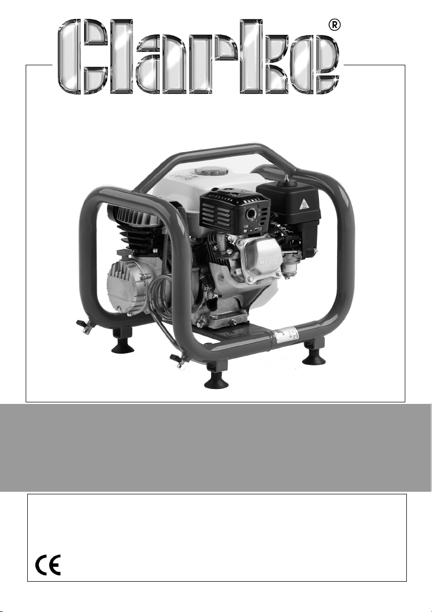
AIR COMPRESSOR
MODEL NO: CFP11F
PART NO: 2090908
OPERATING & MAINTENANCE
INSTRUCTIONS
ORIGINAL INSTRUCTIONS GC0621 rev 2
Page 2
INTRODUCTION
Thank you for purchasing this CLARKE Engine Driven Compressor.
Before attempting to use this product, please read this manual thoroughly and
follow the instructions carefully. In doing so you will ensure the safety of yourself
and that of others around you, and you can look forward to your purchase
giving you long and satisfactory service.
IMPORTANT
WARNING: THIS SYMBOL IS USED THROUGHOUT THE USER GUIDE WHEN
THERE IS A RISK OF PERSONNAL INJURY. MAKE SURE THAT THESE
WARNINGS ARE READ AND UNDERSTOOD AT ALL TIMES.
CAUTION: THIS SYMBOL IS USED THROUGHOUT THE USER GUIDE WHEN
THERE IS A RISK OF DAMAGE TO THE PRODUCT. MAKE SURE THAT THESE
CAUTIONS ARE READ AND UNDERSTOOD AT ALL TIMES.
GUARANTEE
This product is guaranteed against faulty manufacture for a period of 12
months from the date of purchase. Please keep your receipt which will be
required as proof of purchase.
This guarantee is invalid if the product is found to have been abused or
tampered with in any way, or not used for the purpose for which it was
intended.
Faulty goods should be returned to their place of purchase, no product can
be returned to us without prior permission.
This guarantee does not effect your statutory rights.
2
Parts & Service: 020 8988 7400 / E-mail: [email protected] or [email protected]
Page 3

GENERAL SAFETY PRECAUTIONS
Before using your compressor, read and pay attention to the following safety
guidelines.
1. Make sure that all persons using the compressor have read and fully
understand these operating instructions and had any necessary training
2. Compressed air is dangerous. DO NOT point a jet of air at persons or
animals or discharge compressed air against the skin.
3. Repairs must only be carried out by a qualified engineer. If problems occur,
contact your CLARKE dealer.
4. Before carrying out any maintenance, make sure that the pressure is
released from the air receiver.
5. DO NOT leave pressure in the air receiver overnight or when transporting.
6. DO NOT adjust or tamper with the safety valve. The maximum pressure is
set at the factory.
7. DO NOT operate in wet or damp conditions. Keep the compressor dry at all
times. Similarly, clean air will allow the compressor to work efficiently. Do
not use in dusty or otherwise dirty locations.
8. Some metal parts can become hot during operation. DO NOT touch these
until the compressor has cooled down.
9. ALWAYS set the pressure regulator to the recommended setting for the air
tool being used.
10. When spraying flammable materials e.g. cellulose paint, ensure that there
is sufficient ventilation and keep clear of any source of ignition.
11. DO NOT use this compressor in explosive atmospheres.
12. DO NOT operate this compressor in a confined space unless additional
ventilation is provided.
13. Before spraying any material always consult paint manufacturers
instructions for safety and usage.
14. Wear PPE such as goggles to protect your eyes from flying particles. Face
masks will protect you against paint spray and fumes.
15. This compressor will produce noise levels in excess of 70dB(A). Persons
working near the compressor must be equipped with ear protection.
16. Make sure that air hoses are not kinked or wrapped around the compressor
and not subjected to strain.
3
Parts & Service: 020 8988 7400 / E-mail: [email protected] or [email protected]
Page 4
17. When disconnecting air hoses from your compressor, make sure that the air
supply is turned off at the outlet and vent all pressurised air from within the
air receiver.
18. Make sure that children and animals are kept well away from the
compressor and any airline equipment attached to it.
19. Make sure that any equipment or air tool used in conjunction with your
compressor has a safe working pressure exceeding that of the compressor.
20. Take care when transporting the compressor to prevent tipping over with
resultant spillage of fluids.
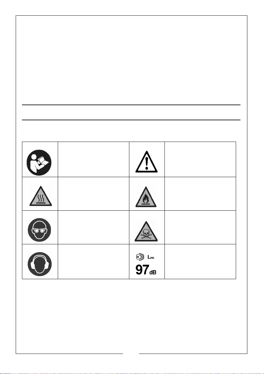
SAFETY SYMBOLS
The following safety symbols are found on the product.
Refer to instruction
manual/booklet.
Hot surface-Do not
touch
Wear eye protection Toxic fumes may be
Wear ear protection This compressor
Warning or Caution
Hazard of flammable
materials
emitted
produces high noise
level during operation.
4
Parts & Service: 020 8988 7400 / E-mail: [email protected] or [email protected]
Page 5
BEFORE USE
POSITIONING THE AIR COMPRESSOR IN THE WORKPLACE
1. ALWAYS carry the compressor using the handle.
2. DO NOT lift by (or put strain on) valves or hoses.
3. Before starting, ensure the compressor is standing on a firm level surface
which does not exceed 10
4. Ensure the environment is dry and dust free.
5. Ensure there is adequate ventilation for:
• Air intake to the compressor pump and engine.
• Cooling for the compressor pump and engine.
• Engine exhaust gases.
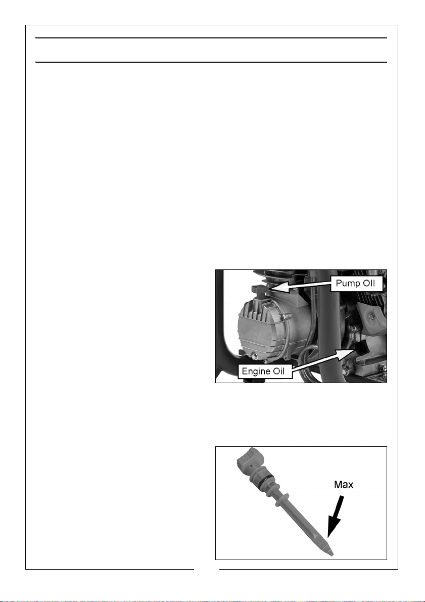
FILING WITH OIL
The engine and compressor are
supplied without oil inside.
A 1 litre bottle of dual purpose oil is
provided in the box and must be
added before use (approx 0.6 L to
the engine and 0.4 L to the
compressor).
For future use, suitable oils are
available from your CLARKE dealer:
1 litre of SAE30 Engine oil - Part No.
3050852
1 litre of SAE30 Air Compressor oil - Part No. 3050796
o
incline, either transversely or longitudinally.
AIR COMPRESSOR (PUMP)
Remove the compressor dipstick and
add 0.4 L of compressor oil to the
compressor. Check the oil level on
the dipstick
5
Parts & Service: 020 8988 7400 / E-mail: [email protected] or [email protected]
Page 6
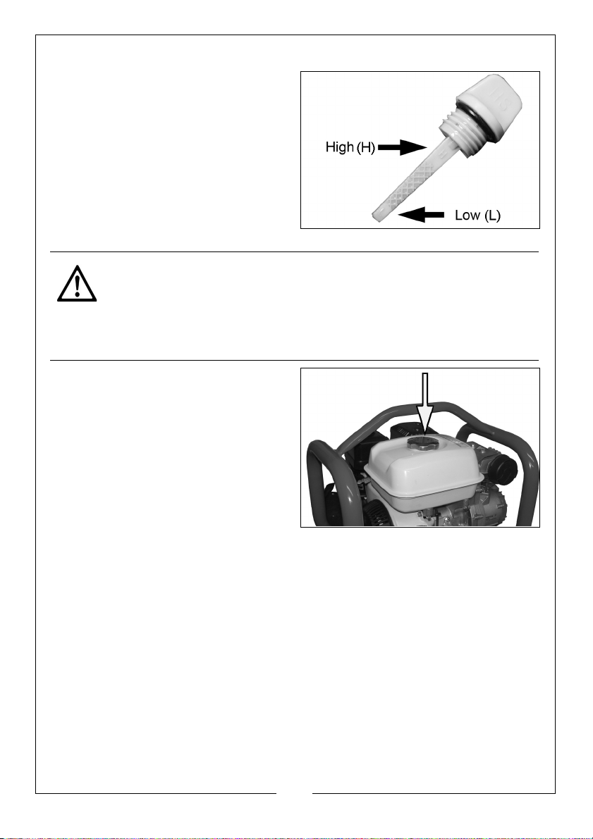
ENGINE
Remove the engine dipstick and add
0.6 L of engine oil to the engine.
Check that the oil level on the
dipstick is within the hatched area
when the dipstick is removed from
the engine.
Ensure the oil level is visible between
the high (H) and low (L) marks on the
engine dipstick.
ADDING FUEL
CAUTION: DO NOT SMOKE
CAUTION: LET A HOT ENGINE COOL BEFORE REFULING
CAUTION: KEEP FUEL OUT OF REACH OF CHILDREN
CAUTION: ENSURE GOOD VENTILATION AWAY FROM SOURCES OF
IGNITION
Remove the filler cap and fill the tank
with unleaded fuel. (Max capacity
1.8 L)
• Use a funnel to avoid
accidental spillage of fuel.
• If fuel is spilled it must be
cleaned from the unit and
surrounding area before
attempting to start the engine.
• Do not overfill.
6
Parts & Service: 020 8988 7400 / E-mail: [email protected] or [email protected]
Page 7
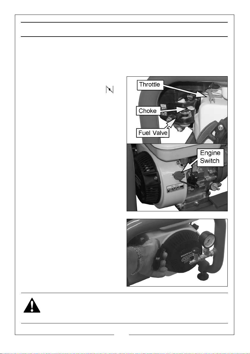
STARTING AND USING THE COMPRESSOR
STARTING THE ENGINE FOR THE FIRST TIME
NOTE: For first time operation, do not connect the air hose or any tools
and proceed as follows:
1. Turn fuel valve to the ON position.
2. Set the choke lever to the
(starting) position.
3. Set the engine switch to the “I”
(ON) position.
4. Hold the starting handle firmly and
pull lightly until you start to feel
resistance, then pull sharply to
start the engine.
NOTE: You may have to do this
more than once.
WARNING: ONCE THE ENGINE HAS STARTED, ALLOW THE STARTING
HANDLE TO RECOIL SLOWLY TO AVOID INJURY/DAMAGE AS IT WHIPS
BACK.
7
Parts & Service: 020 8988 7400 / E-mail: [email protected] or [email protected]
Page 8
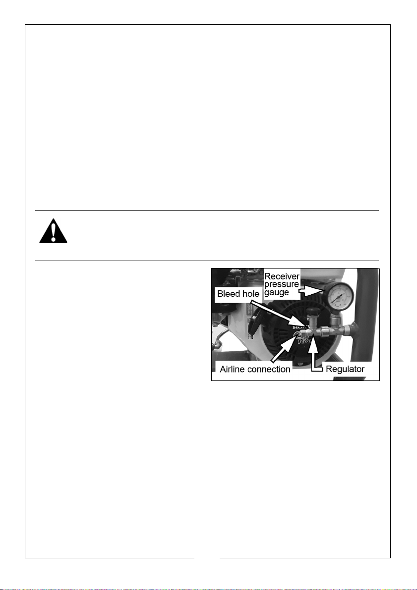
5. When the engine is running steadily, gradually return the choke lever to the
normal running position (to the right).
6. When the engine is running steadily, turn off and attach an air hose to the
compressed air outlet and to the air driven tool.
OIL ALERT SYSTEM
An oil alert system is fitted to prevent engine damage caused by insufficient oil
in the crankcase. Before the oil can fall below a safe limit the oil alert system
will automatically stop the engine although the throttle lever remains in a
running position.
If the engine stops and will not re-start, check the engine oil level before
troubleshooting other areas.
ATTACHING AIR TOOLS
WARNING: BEFORE CONNECTING AIR TOOLS, MAKE SURE THAT YOU
READ THE INSTRUCTIONS SUPPLIED WITH THE TOOL. ENSURE THAT THE AIR
TOOL IS SUITABLE FOR USE WITH THIS COMPRESSOR AND HOSE
SPECIFICATIONS.
1. Attach the air hose to the air
outlet using an appropriate
connector.
2. Attach the air tool to the other
end of the air hose.
• If using snap couplings, use a
whip end, available from your
CLARKE dealer.
3. Restart the engine and allow
pressure to build up in the
receiver.
• The gauge will show the available pressure in the receiver.
4. Check the system for air leaks. If any are apparent, stop the engine and
operate the air tool until the air pressure is at zero before rectifying leaks.
NOTE: A self-relieving regulator is fitted which will vent excess air pressure
from the bleed hole when the pressure reaches the maximum.
operating pressure for the compressor.
5. Turn the pressure regulator (clockwise to increase pressure) and proceed
to use your air tool in accordance with its own product instructions.
8
Parts & Service: 020 8988 7400 / E-mail: [email protected] or [email protected]
Page 9
SUBSEQUENT STARTING
1. Connect the air hose to the air outlet and tool and set the pressure
regulator to zero pressure (turned fully anticlockwise).
2. Start the engine and allow pressure to build up.
3. When the pressure in the receiver has built up and air is expelled at the
vent hole, turn the outlet pressure regulator clockwise so that the desired
pressure is shown on the pressure gauge.
4. Check for air leaks at the air tool and connectors before proceeding.
STOPPING THE COMPRESSOR
1. At the end of the day, stop the engine by turning the engine switch to OFF
and closing the fuel valve.
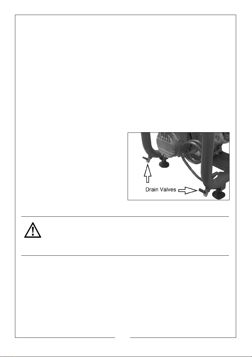
2. Put a container below the drain valve to collect the condensate.
3. Open the drain valves slowly.
• Condensation will drain from
the air receiver.
4. Close the drain valve when the air
receiver has fully drained.
5. Turn the air regulator fully
anticlockwise to close off the air
supply.
6. Operate the air tool to discharge
any pressure in the air line before disconnecting the airline and the air tool.
CAUTION: TAKE CARE NOT TO TOUCH THE ENGINE OR COMPRESSOR AS
THEY REMAIN HOT FOR SOME TIME AFTER USE.
CAUTION: DO NOT UNDER ANY CIRCUMSTANCES ATTEMPT TO REMOVE
THE AIR TOOL OR DISCONNECT THE AIR HOSE UNTIL YOU ARE SATISFIED
THAT THE PRESSURE HAS BEEN RELEASED.
9
Parts & Service: 020 8988 7400 / E-mail: [email protected] or [email protected]
Page 10
COMPRESSED AIR REQUIREMENTS
WARNING: COMPRESSED AIR CAN BE DANGEROUS. ENSURE THAT YOU
ARE FAMILIAR WITH ALL PRECAUTIONS RELATING TO THE USE OF A
COMPRESSED AIR SUPPLY.
• If an unusually long air hose is required, (over 8 metres), the line
pressure or the hose inside diameter may need to be increased.
• The air hose must be rated at least 150% of the maximum operating
pressure of the tool.
• If an automatic in-line lubricator/ filter is used it will keep the air tool
in good condition but should be regularly checked & topped up
with oil. CLARKE air-line oil should be used and the lubricator
adjusted to approx 2 drops per minute.
• Never exceed the maximum operating pressure for the air tool.
Higher pressures and contaminated air will shorten the life of the tool
due to faster wear and is a possible safety hazard.
MAINTENANCE
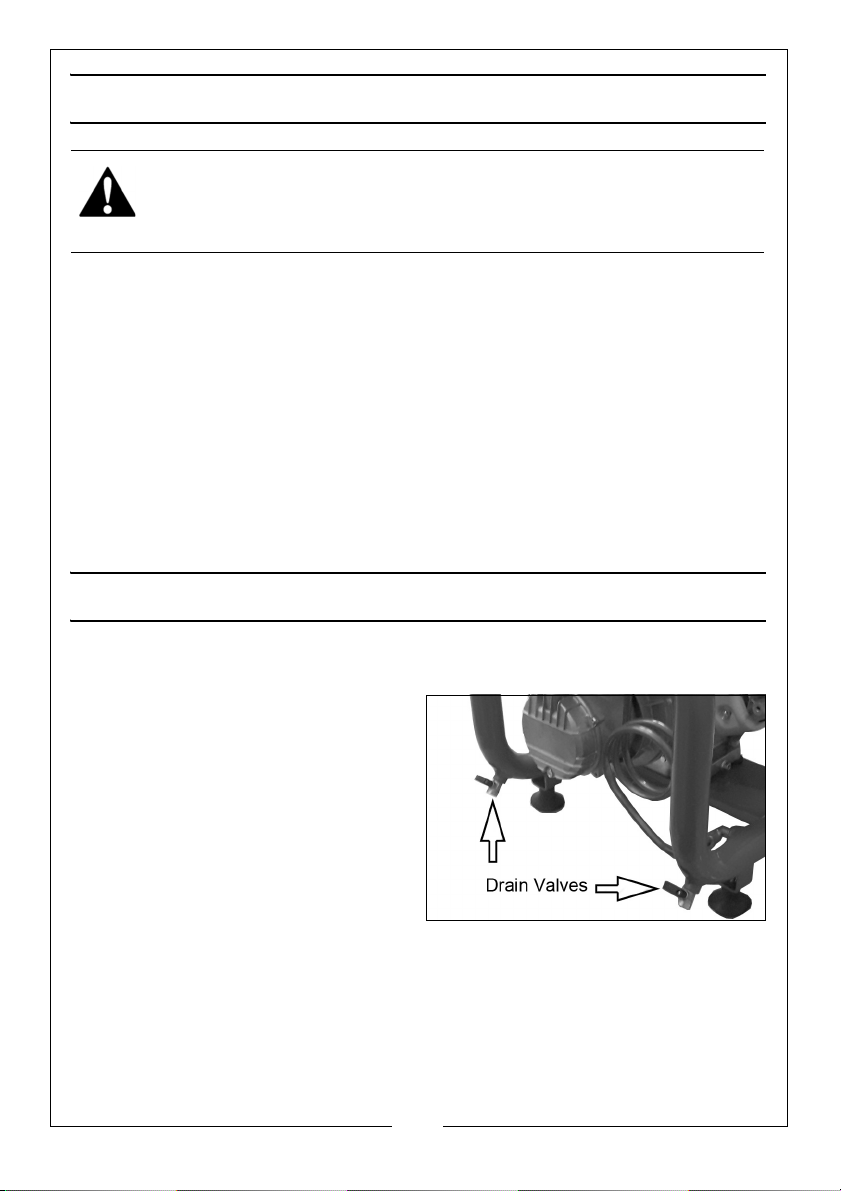
DRAIN THE AIR RECEIVER (DAILY/BEFORE USE)
After use, always open the drain
valve(s) to make sure that any
condensate is drained off.
CHECK OIL (DAILY)
1. Check the engine oil level is
between the Low and High marks
on the dipstick and top-up if
necessary.
2. Check the compressor oil level in
the same way.
3. Remove each dipstick and wipe it clean. Insert the dipstick into the hole as
far as it will go, then remove it to check the oil level. Do not overfill. Refit the
dipstick. Top up if necessary as described on pages 5 & 6.
10
Parts & Service: 020 8988 7400 / E-mail: [email protected] or [email protected]
Page 11
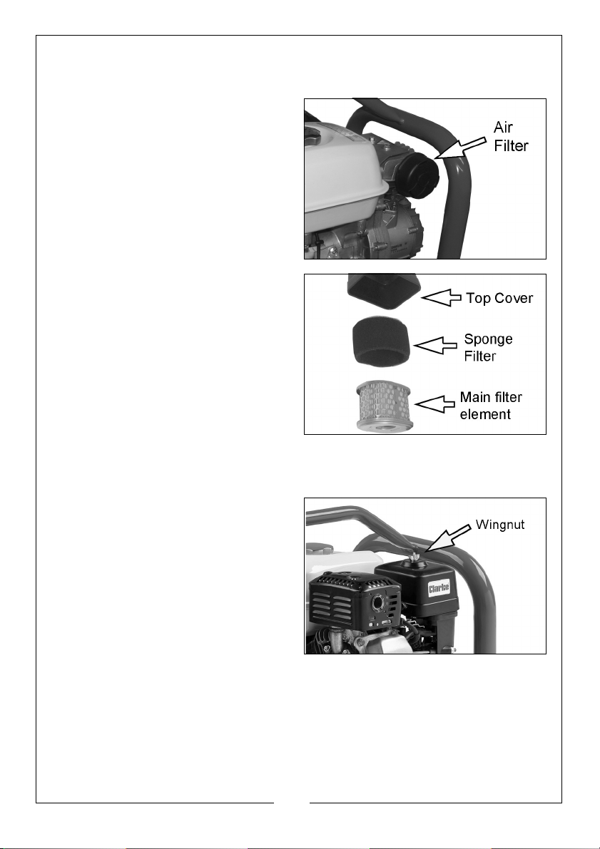
CLEAN THE COMPRESSOR AIR FILTER (MONTHLY)
The air filter must be examined monthly or more often in dusty conditions.
1. Remove the securing wingnut.
2. Lift off the top cover to expose the
filter element.
3. Undo the second wingnut holding
the filter in place and remove the
filter.
4. If necessary, the outer sponge
filter can be carefully cleaned in
warm soapy water.
5. Rinse and let the sponge filter dry
completely before refitting.
6. Clean the main filter element
using a soft brush or a vacuum
cleaner.
• If the main filter element is
damaged it must be replaced.
7. Refit the filters and replace the
cover, securing with the wingnuts
as above.
CHECK THE ENGINE INTAKE FILTER (3 MONTHLY/25 HOURS)
1. Unscrew the engine air intake filter
assembly and prize off the outer
cover by releasing the three small
tabs around the perimeter to
check the filter for cleanliness.
2. Tap the filter against a hard
surface to dislodge loose dirt or
blow through with compressed air.
Take care when using
compressed air and use PPE if
appropriate.
11
Parts & Service: 020 8988 7400 / E-mail: [email protected] or [email protected]
Page 12
3. Do not brush off dirt as it will be
forced into the filter fibres.
4. If necessary, the filter can be
carefully cleaned in warm soapy
water.
5. Rinse and let the filter dry
completely before refitting.
• If the compressor has been
used in a dusty environment,
the filter may need cleaning.
CHANGING THE OIL (6 MONTHLY/50 HOURS)
After the first 100 hours use, replace
the oil using CLARKE compressor oil
and CLARKE SAE30 engine oil.
Thereafter, replace the oil after every
50 hours of operation or every 6
months.
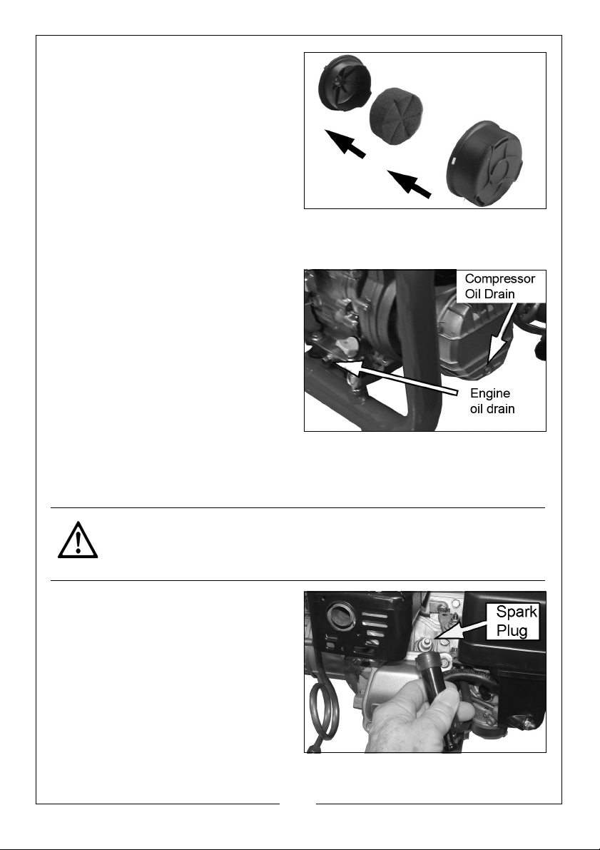
To empty the oil from the either the
compressor or engine remove the oil
drain plug shown and drain into a
suitable container.
Drain the oil when the engine is warm when it will drain quickly and
completely. A new washer should be used when replacing the drain plug.
CHECKING THE SPARK PLUG (YEARLY/EVERY 100 HOURS OF USE)
CAUTION: ALLOW THE ENGINE TO COOL BEFORE REMOVING THE SPARK
PLUG.
1. Pull the spark plug cap and lead
from the spark plug.
2. Use a spark plug spanner to
remove the spark plug.
3. Check for discolouration and use
abrasive to remove any build up
of carbon.
4. Check the condition of the spark
plug and replace if damaged.
12
Parts & Service: 020 8988 7400 / E-mail: [email protected] or [email protected]
Page 13
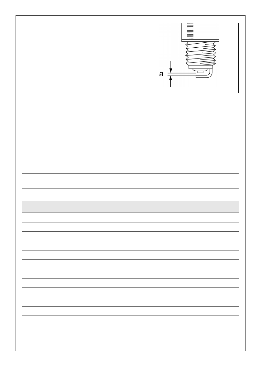
5. Check the spark plug gap (a) with
a feeler gauge. It should be
between 0.6 and 0.7 mm.
• Adjust if necessary by carefully
bending the electrode.
NOTE: Spark plugs are available
from your CLARKE dealer.
6. Re-fit the spark plug taking care
not to cross thread it and tighten
half a turn after the spark plug
seats to compress the washer.
7. Refit the spark plug cap/lead.
EVERY 2 YEARS/250 HOURS
1. Carry out the oil changes.
2. Replace the spark plug and air filter.
3. Request your CLARKE dealer to replace fuel lines.
MISCELLANEOUS SPARE COMPONENTS
No Description Part No
1 Pump Assembly MK238 Complete 1370005
2 Honda Engine (type GP160HQX3) 5HP 8000002
3 Drain Cock 2000221
4 Pressure Gauge 2000171
5 Safety Valve 2000191
6 Manifold 4-way FN011276000
7 Rubber Foot FN116011006
8 Regulator FN347026000
9Spark Plug NGK BPR6ES
10 Engine Air Filter Set HS17210ZE1505
11 Recoil Starter Assembly HS28400ZDK003
12 Starter Pull-cord HS28462ZDK003
13
Parts & Service: 020 8988 7400 / E-mail: [email protected] or [email protected]
Page 14
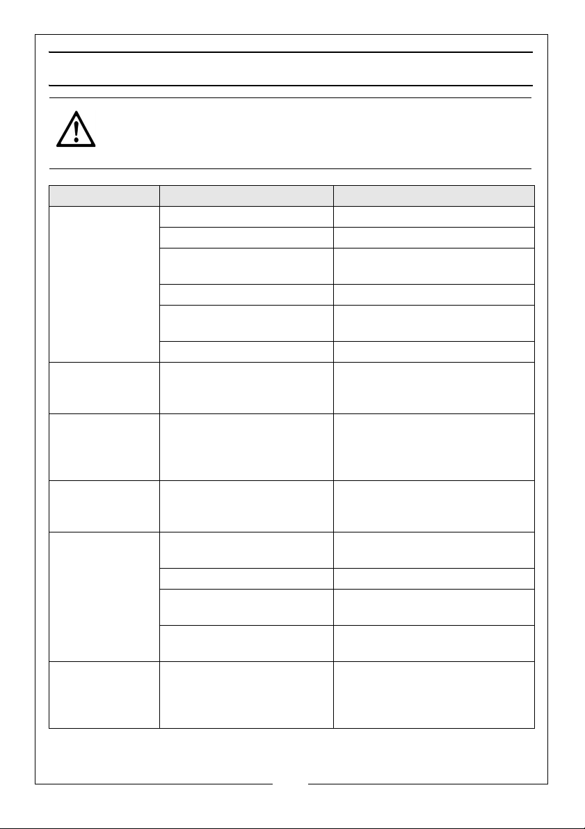
TROUBLESHOOTING
CAUTION: DO NOT TRY TO REPAIR ITEMS IF YOU ARE UNCERTAIN. IF YOU
HAVE ANY QUERIES, CONTACT YOUR CLARKE DEALER.
PROBLEM PROBABLE CAUSE REMEDY
The compressor
fails to start
Engine difficult
to start
Compressor is
constantly ‘on
load’
Compressor has
stopped and
does not start.
Compressor runs
on/off load
more frequently
that usual.
Unusual noise
from compresso
Engine switch is off. Set the engine switch to ‘on’.
No fuel. Add more fuel.
Spark plug damaged or
fouled.
Fuel valve is closed. Open fuel valve
Choke not being used
when starting from cold.
Insufficient starting pull. Pull starter harder.
Regulator blocked/not
working placing
compressor on load.
Defective regulator.
Regulator set to a higher
pressure than the safety
valve’s operating pressure
Faulty or contaminated
carburetor.
Improper or contaminated
fuel.
Dirt in fuel tank. Clean out tank.
Excess condensation in air
receiver.
Leaks in system. Locate any leak using soapy
Unit installed on an
r
unsuitable base.
Compressor damaged
and needs overhaul.
Clean or change the spark
plug.
Set choke to the starting
position shown on page 6.
Drain receiver. Clean or replace
regulator.
Service or replace regulator.
Contact CLARKE service Dept.
Contact your service
department.
Check fuel or replace.
Drain off condensation regularly before use.
water and repair.
Move unit to a more solid base.
Return the machine to your
nearest service agent.
14
Parts & Service: 020 8988 7400 / E-mail: [email protected] or [email protected]
Page 15
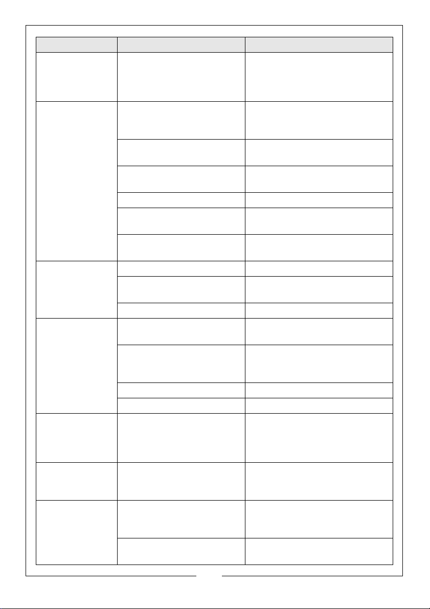
PROBLEM PROBABLE CAUSE REMEDY
Compressor runs
‘on load’ when
Leaks in the system. Locate leaks by means of
soapy water and repair.
no air is being
used.
Compressor is
constantly ‘on
load’ and does
not reach the
set pressure.
Inlet filter blocked. Dismantle and clean or return
the machine to your service
agent.
Leaks from air receiver
fittings.
Locate and tighten any loose
connections.
Valves blocked by dirt. Contact your CLARKE service
department.
Pressure gauge defective. Replace pressure gauge.
Air leaks from cover or
drain plugs.
Machine too small in
Empty air receiver and change
any leaking seals.
Obtain larger compressor.
relation to air consumption.
Oil in the air
delivered
Sump is over full. Reduce to correct level.
Cylinder parts badly worn. Contact your service
department.
Intake air filter blocked. Clean/change air filter.
Compressor’s oil
consumption
increasing
Too much oil in compressor.
Leaks around crankcase.
Working temperature of
compressor too high due
to insufficient cooling.
Check oil level 2 or 3 minutes
after stopping.
Contact service department.
Increase ventilation to air
compressor.
Cylinder worn. Contact service department.
Intake air filter blocked. Clean or replace.
Oil level rises in
compressor
though none
Condensation in
compressor pump.
Drain oil completely to remove
condensate and contami-
nated oil.
has been added
Condensation
at air outlet
Compressor taking in air
which is too warm.
Obtain better fresh air supply to
compressor.
points
Engine cuts out
and will not restart.
Lack of oil has caused the
‘low oil cut-out’ to trip and
stop the engine.
Top up engine oil as shown on
page 5.
Check for low fuel level. Ensure engine has cooled and
is safe to re-fuel.
15
Parts & Service: 020 8988 7400 / E-mail: [email protected] or [email protected]
Page 16
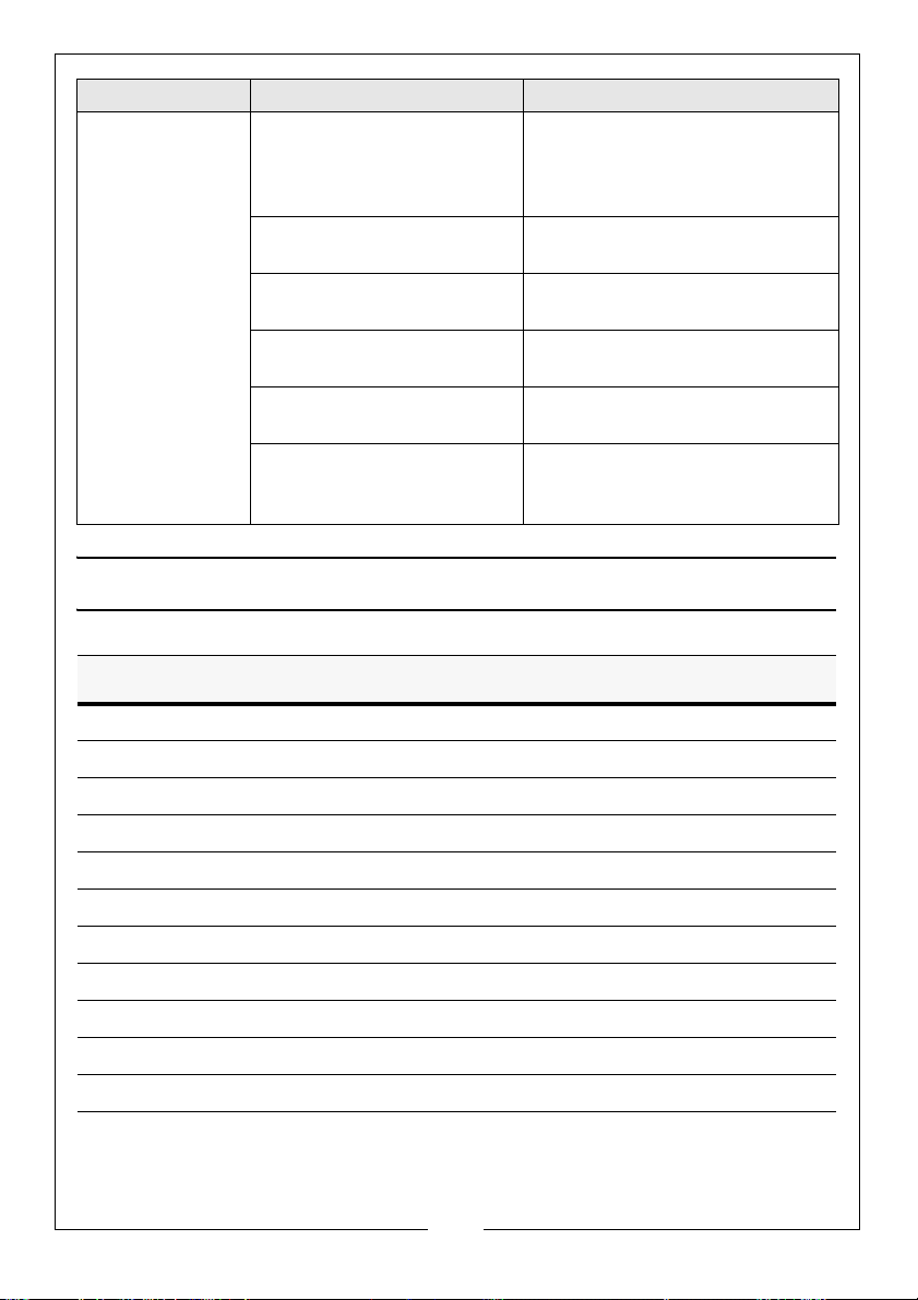
PROBLEM PROBABLE CAUSE REMEDY
Compressor
becomes too
hot.
Insufficient ventilation. See that sufficient air is supplied
to flywheel or fan of compressor
and that hot air is properly
vented.
Oil level too low (check
after stopping).
Blown head gasket. Contact CLARKE service
Dirt on cooling fins or inlet
filter.
Unit working at too high a
pressure.
Compressor being overworked and running
continuously.
Top up oil.
department.
Clean cooling fins and inlet filter
Contact CLARKE service
department.
Connect to a supplementary
compressor or install a larger
mode.
SPECIFICATIONS
MODEL CFP11F
Engine type Honda GP160
Pump type MK238
Air Receiver size 3.1 litres
Max Output Pressure 100 psi
Air Output volume 7.77 cfm
Outlet connector 1/4” BSP Male
Dimensions (L x W x H) 380 x 490 x 470 mm
Guaranteed Sound Power Level 97 dB(A)
Weight 26.4 kg
Engine Oil capacity 0.6 L
Fuel tank capacity 1.8 L
16
Parts & Service: 020 8988 7400 / E-mail: [email protected] or [email protected]
Page 17
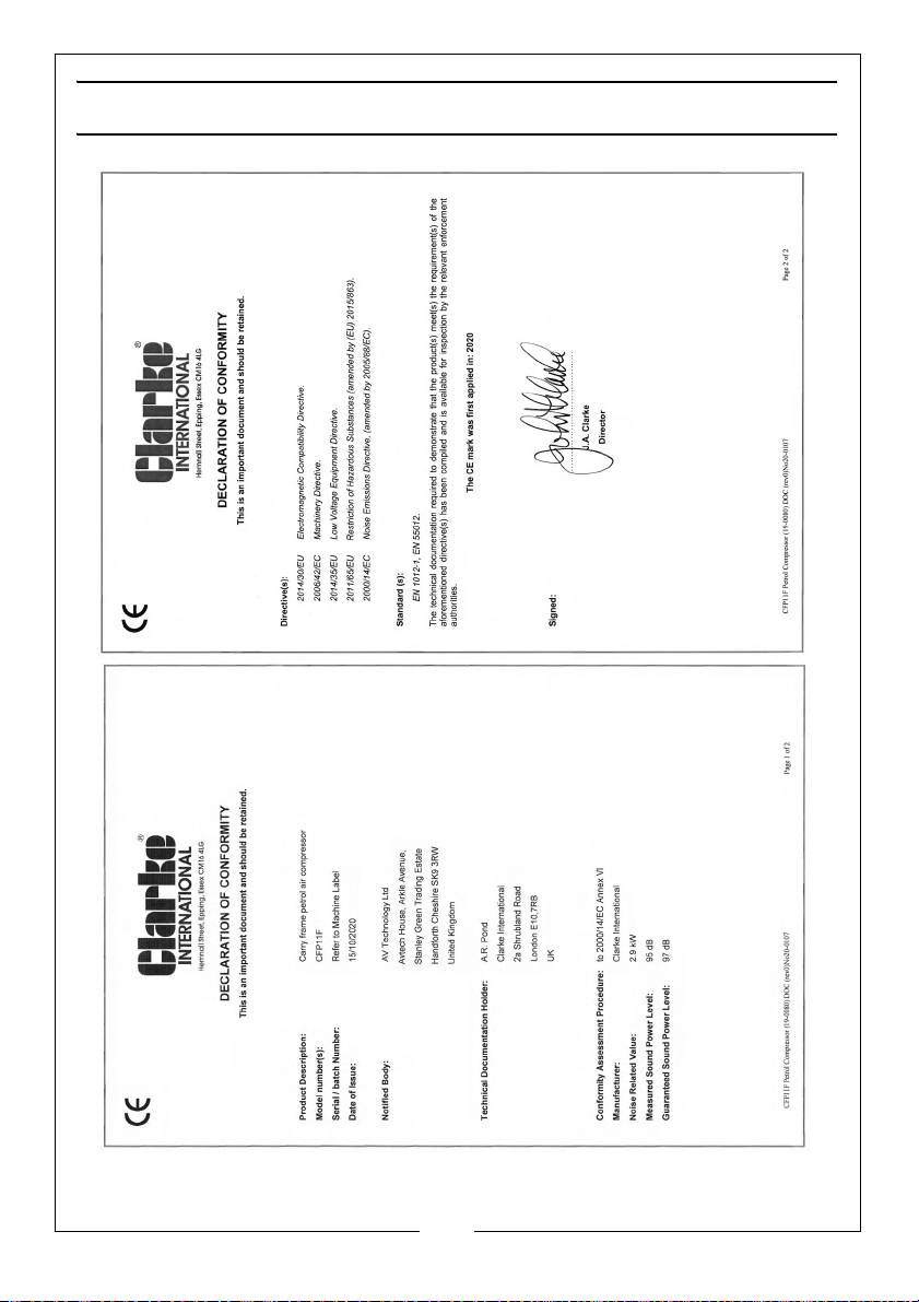
DECLARATION OF CONFORMITY
17
Parts & Service: 020 8988 7400 / E-mail: [email protected] or [email protected]
Page 18
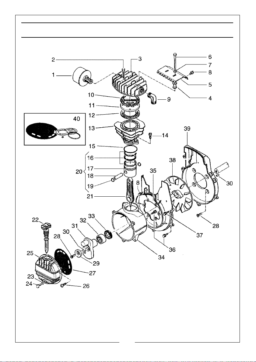
COMPRESSOR COMPONENTS
18
Parts & Service: 020 8988 7400 / E-mail: [email protected] or [email protected]
Page 19
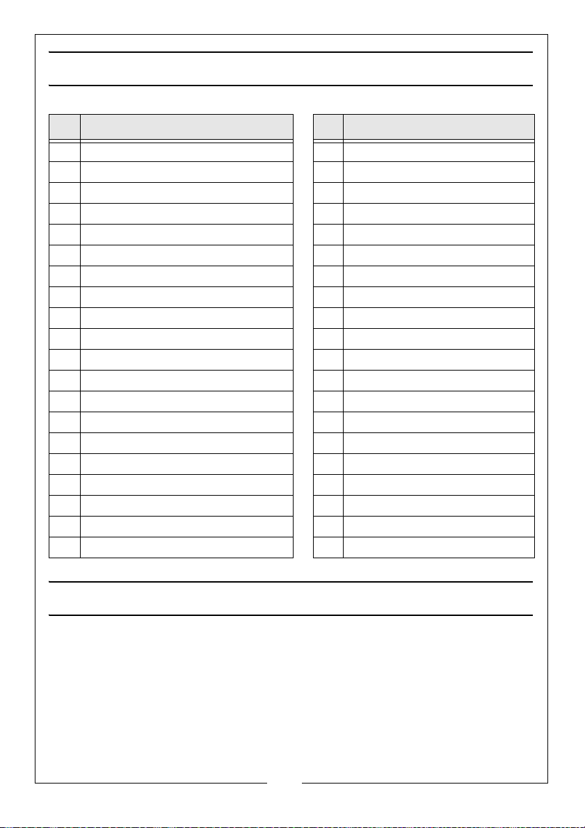
COMPRESSOR COMPONENTS
No Description No Description
1 Air Filter Assembly 21 Connecting Rod
2 Head Bolt M6 x 45 22 Dipstick
3 Cylinder Head 23 Washer
4 Spacer 24 Screw M6 x 10
5 Heat Shield 25 End Casing
6 Screw M6 x 70 26 Screw
7 Washer 6.5 x 18 27 Gasket
8 Screw M5 x 18 28 Screw
9 Elbow 29 Eccentric Lobe
10 Gasket 30 Key
11 Valve Plate 31 Crankshaft
12 Gasket 32 Bearing
13 Cylinder 33 Seal
14 Screw M8 x 20 34 Crankcase
15 O-Ring 35 End Casing
16 Piston Ring Set 36 Screw M5 x 20
17 Piston 37 Screw M5 x 25
18 Gudgeon Pin 38 Fan
19 Circlip 39 End Casing
20 Piston Assembly 40 Gasket Kit
ENVIRONMENTAL PROTECTION
DISPOSAL OF UNWANTED MATERIALS
One of the most damaging sources of environmental pollution is oil products.
Never throw away used oil with domestic refuse or flush it down a sink or drain.
Collect any oil in a leak proof container and take it to your local waste
disposal site. Should any components become completely unserviceable and
require disposal plastic and metal should be disposed of according to local
regulations.
19
Parts & Service: 020 8988 7400 / E-mail: [email protected] or [email protected]
Page 20
 Loading...