

Page 1

Owner’s & Installation Manual
XC7420
4/3/2 Channel Full-Range Class D
System Amplifi er with DSP
Page 2

2
ENGLISH
THANK YOU
Congratulations on your purchase of a Clarion XC7 Series amplifi er. This series of ultra
high speed digital switching amplifi ers was designed in the United States to offer sound
quality that exceeds that of many conventional Class AB designs while offering excellent
effi ciency. When installed and confi gured properly, XC7 amplifi ers will bring a new level
of realism and impact to your mobile entertainment system. To get the best performance
from your amplifi er, Clarion recommends that you have this amplifi er installed and
confi gured by an experienced professional.
XC-TUNE SOFTWARE AND DSP SETUP
The XC7420 amplifi er is designed to provide the highest possible performance from your
mobile entertainment system. In order to maximize the amplifi er’s ability to produce a
stable and accurate soundstage, all controls for the amplifi er have been integrated into the
Digital Signal Processor (DSP) circuitry of the amplifi er. There are NO analog controls on
this amplifi er.
A personal computer (laptop, netbook or tablet) running a Windows operating system
(Version 7, 8 or 10) with a USB 2.0 port is required to set up the XC7420 amplifi er using
the XC-Tune software application. The use of an Apple computer running Windows in
any kind of emulator mode (BootCamp, etc) is not supported. Computers connected
to the XC7420 should ideally be battery powered. The potential for ground loops from
12V Inverters or external power sources can lead to damage. If you aren’t 100% sure,
please operate the computer from battery power alone. Damage caused by improper
communication with any XC7 amplifi er is not covered under the manufacturer’s warranty.
The XC-Tune Operators Manual can be found at: www.clarion.com/ca/
ABOUT THE MANUAL AND WARRANTY
This manual describes the basic requirements to install the Clarion XC7420 amplifi er. The
installation and confi guration of this amplifi er can be quite complex. If you do not possess
the necessary knowledge, experience and/or tools to perform this installation, please
contact your local authorized Clarion dealer to arrange for professional installation. Keep
all instructions and your sales receipt for future reference and warranty purposes.
XC7420 AMPLIFIER FEATURES
The Clarion XC7 Series of amplifi ers are designed with performance and convenience in
mind. Through the use of state-of-the art Digital Signal Processing and high speed output
devices, these amplifi ers offer a level of sound quality that has been unheard of in a high
speed switching amplifi er. The XC7420 amplifi er includes the following features:
• Ultra High Speed output devices for dynamic performance
• Pulse Width Modulated MOSFET Power Supply for effi cient power delivery
• Remote Turn-On with muting for silent start-up
• 6 Channel RCA Input
• 2 Channel RCA Output with DSP Processing
• 2 Ohm Stereo, 4 Ohm Mono Stable
• XC-Tune DSP (Input Mixing, Sensitivity, Crossovers, EQ and Time Alignment)
• DSP Confi gurable BC2 Remote Level control Included
• Speaker level input RCA adapters included
• TRI-ON Auto-Sense turn-on detection for OEM integration
• Corrosion resistant power, speaker and RCA connections
• Circuit Boards with a conformal coating to resist moisture damage
• Low Profi le design with corrosion resistant high effi ciency aluminum heat sink
Page 3
3
ENGLISH
WARNING
Clarion products are capable of producing high sound pressure levels that can damage
your hearing and make it diffi cult for the driver of the vehicle to hear other cars or
emergency vehicles. Clarion wants you as a customer for life - please be responsible at all
times while enjoying your audio system. Clarion takes no responsibility for any personal
injury, loss, damage or loss of income associated with the use, or misuse of this product.
Please refer to the included warranty statement for details.
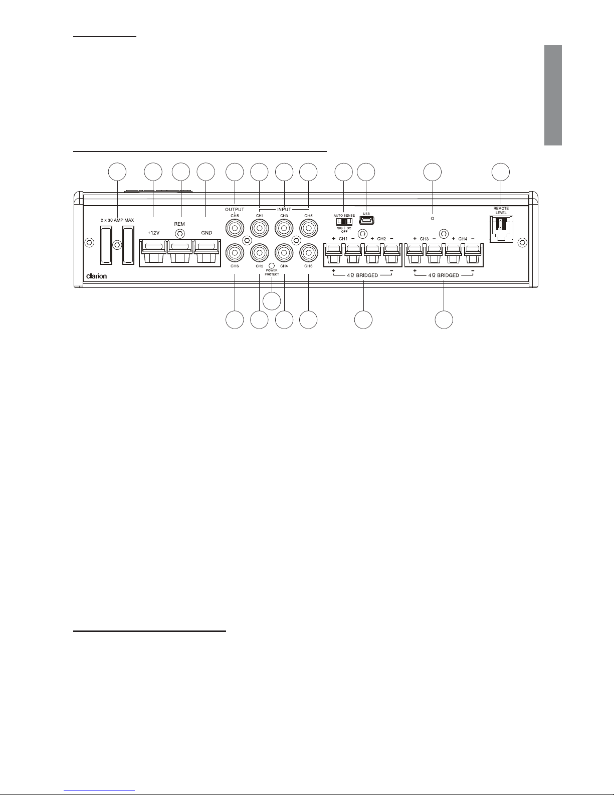
XC7420 CONNECTIONS AND CONTROLS
1. Two 30A ATO Fuses
2. +12V Constant Power Source
3. Remote Turn-On Connection
4. Ground Connection
5. Channel 5 Output RCA Connection
6. Channel 1 Input RCA Connection
7. Channel 3 Input RCA Connection
8. Channel 5 Input RCA Connection
9. TRI-ON Channel 1 Auto Sensing Control Switch
10. USB Connection Port
11. XC-Tune Bootloader Activation Switch
12. BC2 Remote Level Control Connection Jack
13. Channel 6 Output RCA Connection
14. Channel 2 Input RCA Connection
15. Power/Protect LED
16. Channel 4 Input RCA Connection
17. Channel 6 Input RCA Connection
18. Channel 1&2 Speaker Output Terminals
19. Channel 3&4 Speaker Output Terminals
MARINE READY DESIGN
All Clarion XC7 amplifi ers are Marine Ready. This means that the components used to
construct the amplifi er are, as much as possible, designed to withstand exposure to the
high humidity conditions commonly associated with marine applications. The Marine
Ready features include aluminum heat sinks, stainless steel hardware and a conformal
coating on the circuit boards.
The Marine Ready designation does not in any way imply that Clarion XC7 amplifi ers are
waterproof or water resistant. These amplifi ers must be installed in a location that will
remain dry at all times.
1 2 3 4
6 875 9
15
18 191614 17
1110
13
12
Page 4
4
ENGLISH
GENERAL FUNCTION EXPLANATION
Setting Mixer/Gain Settings in XC-Tune
This adjustment is provided for each channel in order to adjust the amplifi er sensitivity
so that it will produce maximum power given a variety of different input signal voltages.
Setting this control correctly will ensure that you get maximum performance from your
amplifi er and is critical to ensuring that minimal noise and distortion is produced.
Clarion recommends the use of an Oscilloscope or distortion detecting device such as the
SMD DD-1 or DD-1+ Distortion Detector to properly set amplifi er sensitivity. A headroom
setting of approximately 10dB will help to ensure that music that is recorded at low levels
can still be reproduced at high volume levels. With this setting, it is the responsibility of the
operator to use the amplifi er in a manner that will not produce audible distortion.
Procedure (Oscilloscope) Method:
1. Obtain a test disc with a selection of Sine Waves recorded at -5dB and -10dB.
2. Turn the gain all the way down on the amplifi er (to the left).
3. Connect the ground terminal of the scope lead to the shield of the RCA cable
coming from the source unit. Do no connect the scope lead to the speaker output
terminals.
4. Connect the scope probe to a speaker terminal on the channel you want to adjust.
5. Select a Sine wave frequency that is well away from the chosen crossover frequency.
For midrange speakers use 1kHz at -5dB, use 40Hz at -10dB for subwoofers.
6. Turn the source unit up as high as possible without distortion.
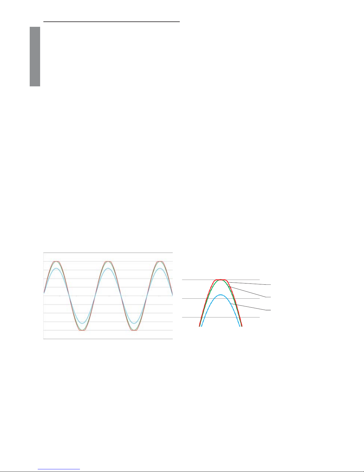
7. Monitor the output waveform of the amp on the scope.
8. Increase the sensitivity of the amplifi er until the scope waveform shows a small fl at
spot on the top or bottom of the waveform. See Figure 2 for an example of what to
look for.
SMD DD-1 Method:
1. Following the instructions provided with the DD-1, use the 0dB track to confi rm the
output of the audio signal source is unclipped.
2. Connect the DD-1 to the output of the amplifi er and use an appropriate -5dB or -10dB
track. Increase the gain on the amplifi er until the Distortion LED illuminates
You should be able to turn the volume up to almost full (or wherever your source unit clips/
distorts) without hearing distortion. If you can’t turn the volume up most of the way without
distortion, the sensitivity control is not adjusted properly.
Sine wave unclipped
Clipped Sine wave
Sine wave well bellow clipping
Fig 1 - Sine Wave at different Levels Fig 2 - Close-Up of waveforms
Page 5
5
ENGLISH
GENERAL FUNCTION EXPLANATION - CON’T
TRI-ON Auto Sensing Turn-ON Control Switch
All XC7 amplifi ers feature an automatic turn-on circuit called TRI-ON that will activate the
amplifi er without the need for a connection to the REM terminal. The switch has three
positions - SIG, OFF and DC.
SIG - Signal Detect Mode
In this setting, the amplifi er will monitor Channel 1 input for the presence of an audio
signal. The signal needs to be moderately loud in order for the amplifi er to activate.
NOTE: in some applications,if a speaker is still connected to the wires on this input, the
voltage produced from speakers moving when a door is closed may be adequate to trick
the amp to turn on. This is the least desirable setting.
OFF - Remote Turn-On Connection Mode
In this mode, the amplifi er turns on when a 12V signal is connected to the REM terminal.
This is the preferred method of turning on the amplifi er.
DC - DC Voltage Detection Mode
In this mode, the amplifi er will monitor Channel 1 input for the DC offset voltage produced
by a BTL type amplifi er. To check for the presence of BTL, you can monitor the DC
voltage on the speaker wires of the signal source. When you turn on the source, you
should see 5-6 Volts DC (or more) on the wires. The presence of this DC voltage will
activate the amplifi er.
Remote Turn-On Connection
When +12V is applied to this terminal, the amplifi er will turn on. When installing the
amplifi er with an after market source unit, this wire is typically Blue with a White stripe.
Some OEM source units have a wire that behaves similarly.
Speaker Connections
The XC7420 amplifi er is capable of driving reactive loads with a minimum nominal
impedance of 2 Ohms per channel and 4 Ohms when bridged. When wiring speakers
in stereo, the positive and negative leads from the speakers should connected to the
respective channels positive and negative connections on the amplifi er. When bridging the
amplifi er to drive a mono load, only the outside terminals should be used.
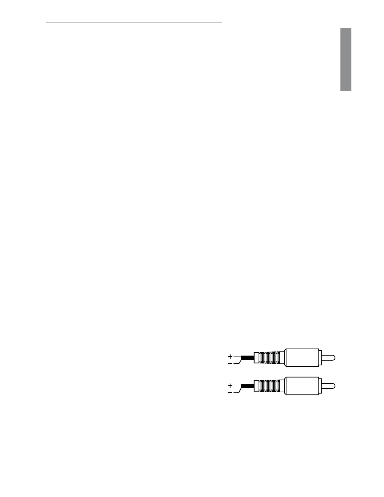
Input RCA Connections
The RCA Input connections should be connected
to the RCA Pre-amp outputs of an after market
head unit. If you are using a head unit or factory
amplifi er that only has speaker level outputs,
please use the high-level input adapters that
are included with each amp. Please wire them
according to the adjacent image. Note, there are components in these connectors used
to attenuate the signal. Do not substitute conventional RCA terminals for these adapters
or damage will occur. Damage from over-driving the input stage of the amplifi er is not
covered under the manufacturer’s warranty.
NOTE: When connecting to the output of a factory amplifi er, you may need to install
load resistors on the amplifi er outputs to compensate for the output fi ltering circuit of the
amplifi er. A 50 Ohm, 5 Watt resistor usually works well.
Red
White
Red
Black
White
Blue
Page 6

6
ENGLISH
GENERAL FUNCTION EXPLANATION - CON’T
USB Connection Port
When connecting your Windows (7, 8 or 10) Laptop or Tablet computer to the amplifi er for
tuning, please connect the included 6’ USB cable to this port. It is recommended to power
the computer from a battery source to completely eliminate the chance of a ground loop
on this connection. If you require more cable length, purchase a longer cable. Do not use
an extension. You will need a Type A to Type Mini-B USB cable. Use as short a cable as
possible for maximum reliability.
XC-Tune Bootloader Activation Switch
This microswitch is used to put the amp into Bootloader mode. The latest version of the
XC-Tune software will automatically put the amplifi er into Bootloader mode to perform
software updates. It is unlikely that this switch will need to be used.
BC2 Remote Level Control Installation
Clarion includes a remote level control called the BC2 with the XC7420. The function of
the BC2 is programmable in the XC-Tune software. You can adjust the operating range of
the control and which channels the control adjust. Please refer to the XC-Tune section of
this manual for details.
The BC2 can be easily disassembled for custom installations. Please ensure that the
contacts on the circuit board never come in contact with any metal surfaces in the vehicle.
INSTALLATION PLANNING AND CONSIDERATIONS
Clarion XC7 amplifi ers are designed for installation in vehicles with 12V electrical systems
and a chassis ground confi guration. While Clarion strongly recommends professional
installation of our products to maximize the performance of the product, installing the
amplifi er yourself can certainly produce impressive results. Please take into consideration
the following when planning your installation.
• Take care in choosing a mounting location for the amplifi er. Clarion does not
recommend mounting an amplifi er to a subwoofer enclosure. Vibration could damage
internal components of the amplifi er.
• Ensure that the screws used to mount the amplifi er will not damage anything
underneath or behind the mounting location such as interconnects, speaker wires,
factory wiring harnesses, computer modules, factory fl uid lines, fuel tanks and more.
Mounting hardware should be suffi cient to ensure that the amp will not come loose in
the event of a vehicle accident.
• All wiring running to and from the amplifi er should be planned so that it’s route does
not bring it in proximity of any high-current devices or computer modules. This will
help to prevent noise from being induced in the audio system.
• XC7 Amplifi ers incorporate balanced differential inputs. As such, Clarion recommends
the use of twisted pair interconnects to ensure that the signal on the center pin and
shield of the interconnect allow this circuitry to perform to the best of its ability in
terms of rejecting unwanted noise.
Page 7

7
ENGLISH
INSTALLATION PLANNING AND CONSIDERATIONS CON’T
• Although the XC7 amplifi ers are suitable for marine installations, they are in no way
water resistant. XC7 amplifi ers should be mounted in a dry, well-ventilated location.
The marine features of the amp are designed to handle humid conditions commonly
associated with installations in boats.
• Amplifi ers dramatically increase the load on the vehicles electrical system. Please
confi rm that the vehicle battery and alternator are in good condition. Clarion
recommends the use of a heavy duty AGM style battery to increase current delivery
and play time. The use of a high quality, low ESR stiffening capacitor will provide
increased instantaneous current to the amplifi er.
• Supplying adequate current to your amplifi er may require that some of the factory
electrical connections under the hood of your vehicle be upgraded. The industry
refers to these upgrades as ‘The Big 3’. Performing these upgrades are optional, but
highly recommend. Additional current delivery capability will increase the performance
and longevity of any electrical component you add to your vehicle. These upgrades
include:
- A new ground wire from the engine in your vehicle to the battery ground terminal.
- A new ground wire from the ground terminal of your battery to the chassis of the
vehicle.
- A new power wire from the output of your alternator to the positive terminal of your
battery.
Some vehicles use aluminum or adhesive-bonded connections between body panels
and will not allow adequate current to pass. Clarion recommends that a parallel
ground wire be installed to decrease resistance in the return path.
INSTALLATION
1. Once a safe and suitable location has been chosen for your amplifi er, remove both
top trim pieces from the amplifi er using a 2mm hex driver. Store the four screws and
trim pieces in a safe location.
2. Locate the amplifi er and mark the mounting hole locations.
3. Remove the amp and pre-drill the mounting holes.
4. Replace the amplifi er and secure with adequate hardware.
5. Replace the upper trim panel and secure.
6. Make all the power, signal and speaker connections to the amp.
7. Complete the remainder of the system installation and fi nish tuning the amplifi er and
system
8. Install the lower trim panel and secure.
Page 8

8
ENGLISH
Power Connections
Your XC7-Series amplifi er can only produce power if it is fed power effi ciently. Clarion
recommends the use of minimum of 4 AWG copper wire for all power and ground
connections. The use of undersized power wiring may result in damage to your amplifi er.
Clarion also recommends performing “The Big Three” upgrade to your electrical system
when any high power amplifi er is being installed. This includes upgrading the power wire
between your battery and the alternator for both positive and ground connections, as
well as the ground connection between the battery and the chassis and/or rear ground
location.
The amplifi er ground connection is the most important connection in terms of reliable and
effi cient operation of your amplifi er. This connection should be made to a solid and secure
point on the vehicle chassis, or directly to the battery. Do not use a seat or seatbelt bolt
as a ground location. All of the sound deadening, paint and primer must be removed from
the chosen ground location. The ground ring terminal(s) should be secured with a bolt and
locking fastener.
NOTE: Many new vehicles are assembled with extensive aluminum materials, composites
and high strength adhesives. Clarion recommends running a ground wire of the same size
as the power wire from the negative terminal of your battery to the ground location of your
amplifi er. This is known as a parallel ground.
Wiring Precautions
Read all of the wiring precautions prior to making any connections. If you are unsure and/
or don’t have the necessary installation hardware, contact your local Clarion dealer to
perform the installation.
1. Before you begin the installation, make sure the vehicle is not running and is in the
OFF position.
2. Disconnect the negative (-) lead of the battery (or batteries) before making any power
connections.
3. When making connections, be sure that each connection is clean and secure.
4. Insulate connections with split loom or heat shrink tubing where possible.
5. A fuse holder and fuse must be installed on the lead coming from the positive (+)
terminal of the battery. This fuse should located as close a possible to the battery
terminal for maximum protection. Clarion does not recommend the use of a circuit
breaker as a protection device.
6. The battery fuse rating should equal the total current consumption at full output of the
amplifi er(s) connected to that wire. Do not install the fuse until the entire installation
has been completed.
+12V
GND
REM
Battery
+-
Fuse
Blue/White
Parallel Ground
Battery
Ground
Chassis
Ground
Page 9

9
ENGLISH
7. When replacing the amplifi er or power wire fuse, always use a fuse with the same
amperage rating. Substituting a higher rating fuse or a slow-blow type can result in
serious damage to the amplifi er or vehicle.
8. When creating passage holes for power wire, interconnect cables and speaker wires,
use grommets and wire loom to eliminate any sharp edges created during drilling.
This will protect the wire from being damaged and help to prevent a short circuit.
TROUBLESHOOTING
Problem Solution
Amplifi er will not turn
on - Power LED off
- Using a digital multi-meter, check for 12V at the +12V
and REM Connections when referenced to the amp ground
connection.
- If the Auto Sensing circuit is being used, try reversing the +
and - connections to the High Level RCA Adapters
Audio stops playing - Thermal protection circuit has shut down amp to protect
the circuitry. Ensure there is adequate ventilation around the
amplifi er.
- Fuse at the battery or amplifi er is blown. Inspect and replace
as required.
- Amplifi er is loaded below the rated impedance limit. Check
wiring and reconfi gure as required.
Amp shuts off at high
volumes
- Amplifi er may not be getting enough power from your vehicle
electrical system. Ensure that during operation, the voltage at
the amplifi er does not drop below 10.6V. Clarion recommends
at least 4 AWG Pure Copper power wire for both +12V and
GND connections.
Distorted Audio - Input gain is not set properly. Adjust as per instructions.
- Source signal is distorting. Reduce source output level.
- Speaker is damaged. Replace as necessary.
Fuse Blows - Amplifi er output may be shorted. Check all wiring.
- Amplifi er may be damaged. Remove all speaker wires
and check functionality. If the fuse blows with no speaker
connection, contact the Clarion Service Department.
Whining or ticking
noise
- The amplifi er may be picking up electrical noise that is
traveling on the ground shield of the interconnect.
1. Check for solid ground connections at the source unit and
amplifi er.
2. Run a ground wire from the amplifi er to the source unit.
3. Re-route the interconnect cables away from sources
of electrical noise. Ensure you are using good quality
shielded interconnects.
- A speaker wire or a passive crossover network may be
picking up electrical noise. Reroute wiring as needed.
Page 10

10
ENGLISH
TROUBLESHOOTING - ERROR CODES
Clarion XC7 amplifi ers use a microcontroller to manage the operation of the amplifi er.
Included in the fi rmware is the ability to detect errors in the functionality of the amplifi er.
The following error code chart can be used to look up the cause of a fault.
The following codes are shown by a red fl ashing pattern of the Power/Protect LED.
Code 1 - Indicates that the power connection voltage is too low. Check all your power
connections. This is most commonly caused by a poor ground connection.
Code 2 - There is an over-current condition on Channel 1-4. This could be caused by a
shorted speaker, a grounded speaker wire or an internal fault. Disconnect all speaker
wires and test again.
Code 3 - The amplifi er has detected the occurrence of short circuits on the last three
power-up attempts. Correct this condition, remove power from the amplifi er for 15 minutes
and try again.
Code 4 - Indicates that the battery connection voltage is too high. Check the functionality
of the vehicle charging system.
Code 5 - This error indicates that there is a DC voltage present on one of the speaker
leads. The amplifi er will need to be serviced.
Code 6 - There is an over-current condition on Channel 5 of the XC7520. This could be
caused by a shorted speaker, a grounded speaker wire or an internal fault. Disconnect all
speaker wires and test again.
Heatsink Over Temperature - This error indicates that the chassis of the amplifi er has
exceeded the recommended operating voltage. Review your choice of installation location,
ensuring that there is adequate airfl ow around the amplifi er. Also check your wiring to
make sure the amplifi er is getting enough voltage and has a good ground connection.
Power Supply Over-Temperature - This error indicates that the power supply of the
amplifi er has exceeded the recommended operating voltage. Ensure that the amplifi er is
getting adequate voltage.
Code 3 - Repeated Short Circuit
Code 4 - Power Supply Over Voltage
Code 1 - Power Supply Under Voltage
Code 2 - Channel 1-4 Short Circuit
Over Temperature - Heatsink
Over Temperature - Power Supply
Code 5 - DC Voltage Speaker Protection
Code 6 - Channel 5 Short Circuit
Turn-On Process
Turn-On Process (after reset)
Page 11
11
ENGLISH
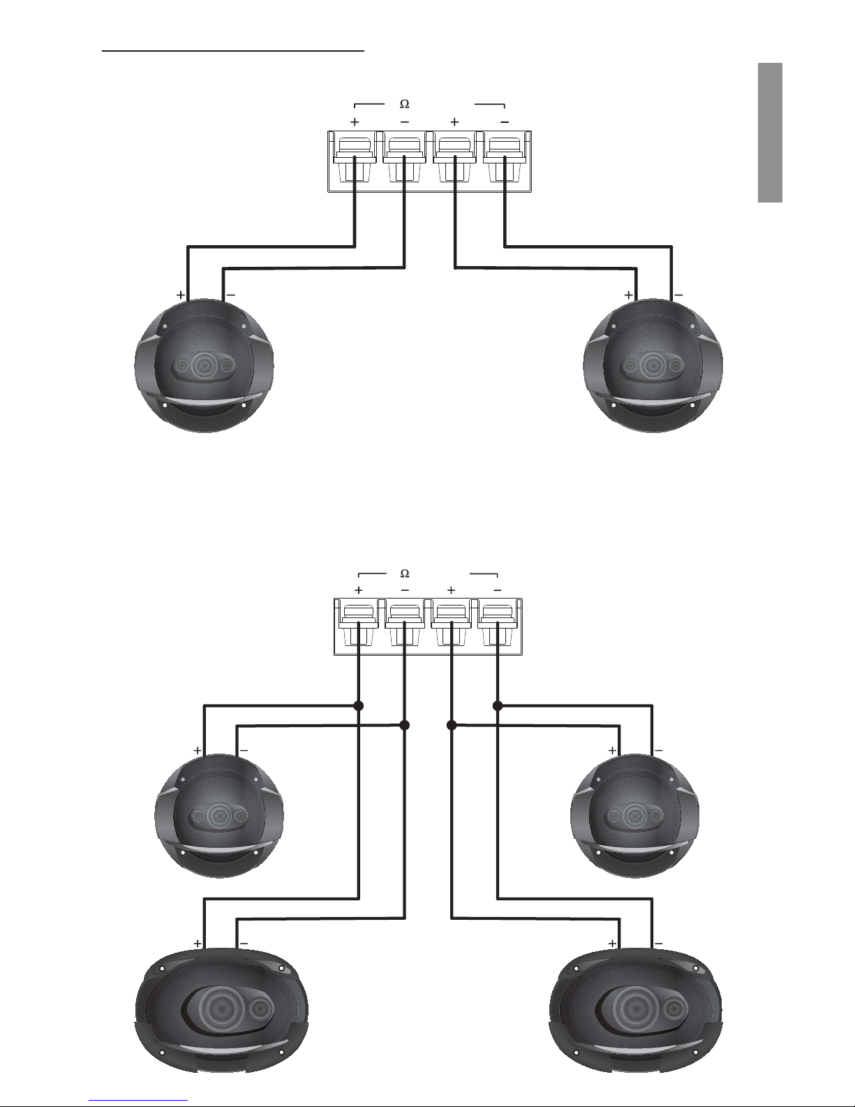
SPEAKER WIRING DIAGRAMS
XC7420 - Two 4 Ohm Speakers - 4 Ohm Stereo
XC7420 - Four 4 Ohm Speakers - 2 Ohm Stereo
BRIDGED
4
CH2
CH1
BRIDGED
4
CH2
CH1
Page 12

12
ENGLISH
SPEAKER WIRING DIAGRAMS
XC7420 - Single 4 Ohm Speaker Bridged
BRIDGED
4
CH2
CH1
Page 13

13
ENGLISH
Specifi cations
XC7420
Frequency Response: <10Hz to 22.4kHz
4 Ohm Stereo Power Output (CEA-2006A) 120W x 4 @ 1.0% THD
2 Ohm Stereo Power Output (CEA-2006A) 180W x 4 @ 1.0% THD
4 Ohm Bridged Power Output (CEA-2006A) 380W x 2 @ 1.0% THD
Signal to Noise Ratio (CEA-2006A) @ 1W/4 Ohms > -77.2 dBA
Effi ciency at Full Power (4 Ohms) 79.70%
Input Sensitivity 200mV to 4V
Page 14

14
ENGLISH
LIMITED WARRANTY
This Clarion product, when purchased from AND installed by an authorized Clarion dealer
in good standing, is warranted against defects in materials and workmanship for a two (2)
year period from the date of original purchase.
All Clarion cables, wires and other accessories, if purchased from an authorized Clarion
dealer are warranted against defects in materials and workmanship for ninety (90) days
from the date of original purchase.
ALL PURCHASES OF CLARION PRODUCTS FROM NON-AUTHORIZED CLARION
DEALERS ARE SUBJECT TO FURTHER WARRANTY RESTRICTIONS AS DESCRIBED
BELOW.
The conditions of this Limited Warranty and the extent of responsibility of Clarion
Corporation of America (“Clarion”) under this Limited Warranty are as follows:
1. IN THE CASE OF THE TWO (2) YEAR LIMITED WARRANTY FOR CLARION
PRODUCTS, PROOF OF DATE OF PURCHASE AND PROOF OF INSTALLATION
BY AN AUTHORIZED CLARION DEALER IS REQUIRED.
2. This Limited Warranty will become void if service performed by anyone other than an
approved Clarion Warranty Service Center results in damage to the products.
3. This Limited Warranty does not apply to any product which has been subject to
misuse, neglect or accident, or which has had the serial number altered, defaced or
removed, or which has been connected, installed, adjusted, operated or repaired,
other than in accordance with the instructions furnished by Clarion.
4. This Limited Warranty does not cover static, noise or other electrical interferences or
labor costs for the removal or re-installation of the unit for repair.
5. The sole responsibility of Clarion under this Limited Warranty shall be limited to the
repair of the products or replacement of the product, at the sole discretion of Clarion.
6. Product must be shipped in its original carton or equivalent carton, fully insured, with
shipping charges prepaid. Clarion will not assume any responsibility for any loss or
damage incurred in shipping.
7. CLARION PRODUCTS PURCHASED FROM A SOURCE OTHER THAN AN
AUTHORIZED CLARION DEALER, INCLUDING ANY AND ALL PURCHASES VIA
THE INTERNET FROM A NON INTERNET AUTHORIZED CLARION DEALER,
SHALL NOT BE COVERED BY ANY CLARION LIMITED WARRANTY TO THE
EXTENT ALLOWED BY APPLICABLE LAW. IN THE EVENT AND TO THE EXTENT
APPLICABLE LAW PROHIBITS ELIMINATION OF WARRANTIES UNDER THESE
CIRCUMSTANCES, THE APPLICABLE LIMITED WARRANTY PERIOD SHALL
BE DEEMED TO BE FIFTEEN (15) DAYS FROM THE DATE OF ORIGINAL
PURCHASE.
8. ALL IMPLIED WARRANTIES EXCEPT TO THE EXTENT PROHIBITED BY
APPLICABLE LAW SHALL HAVE NO GREATER DURATION THAN THE
WARRANTY PERIOD SET FORTH ABOVE. UNDER NO CIRCUMSTANCES
SHALL CLARION BE LIABLE FOR ANY LOSS OR DAMAGE, DIRECT OR
CONSEQUENTIAL, ARISING OUT OF THE USE OR INABILITY TO USE THE
PRODUCT. BECAUSE SOME STATES DO NOT ALLOW LIMITATIONS ON HOW
LONG AN IMPLIED WARRANTY LASTS OR EXCLUSIONS OR LIMITATIONS OF
INCIDENTAL OR CONSEQUENTIAL DAMAGES, THE ABOVE LIMITATIONS OR
EXCLUSIONS MAY NOT APPLY TO YOU.
Page 15

15
ENGLISH
LIMITED WARRANTY CON’T
9. THIS LIMITED WARRANTY GIVES YOU SPECIFIC LEGAL RIGHTS, AND YOU MAY
ALSO HAVE OTHER RIGHTS WHICH VARY FROM STATE TO STATE.
10. The laws of the State of California shall govern and control this limited warranty, its
interpretation and enforcement.
11. Should you have any diffi culties with the performance of this product during the
warranty period, please Contact the dealer you purchased the product from.
Page 16

Clarion Canada Inc.
3800A Laird Road, Unit 6
Mississauga, ON
L5L 0B2
All Rights Reserved. Copyright 2017 Clarion Canada Inc.
Printed in China
 Loading...