

Page 1
Owner’s Manual / Installation Manual
Manuel de l’utilisateur / Manuel d’installation
Bedienungs- & Installationsanleitung
Manuale del proprietario e manuale di installazione
Gebruiks- & Installatiehandleiding
Manual del propietario / Manual de Instalación
Bruks- och installationsanvisning
Manual do Proprietário e Manual de Instalação
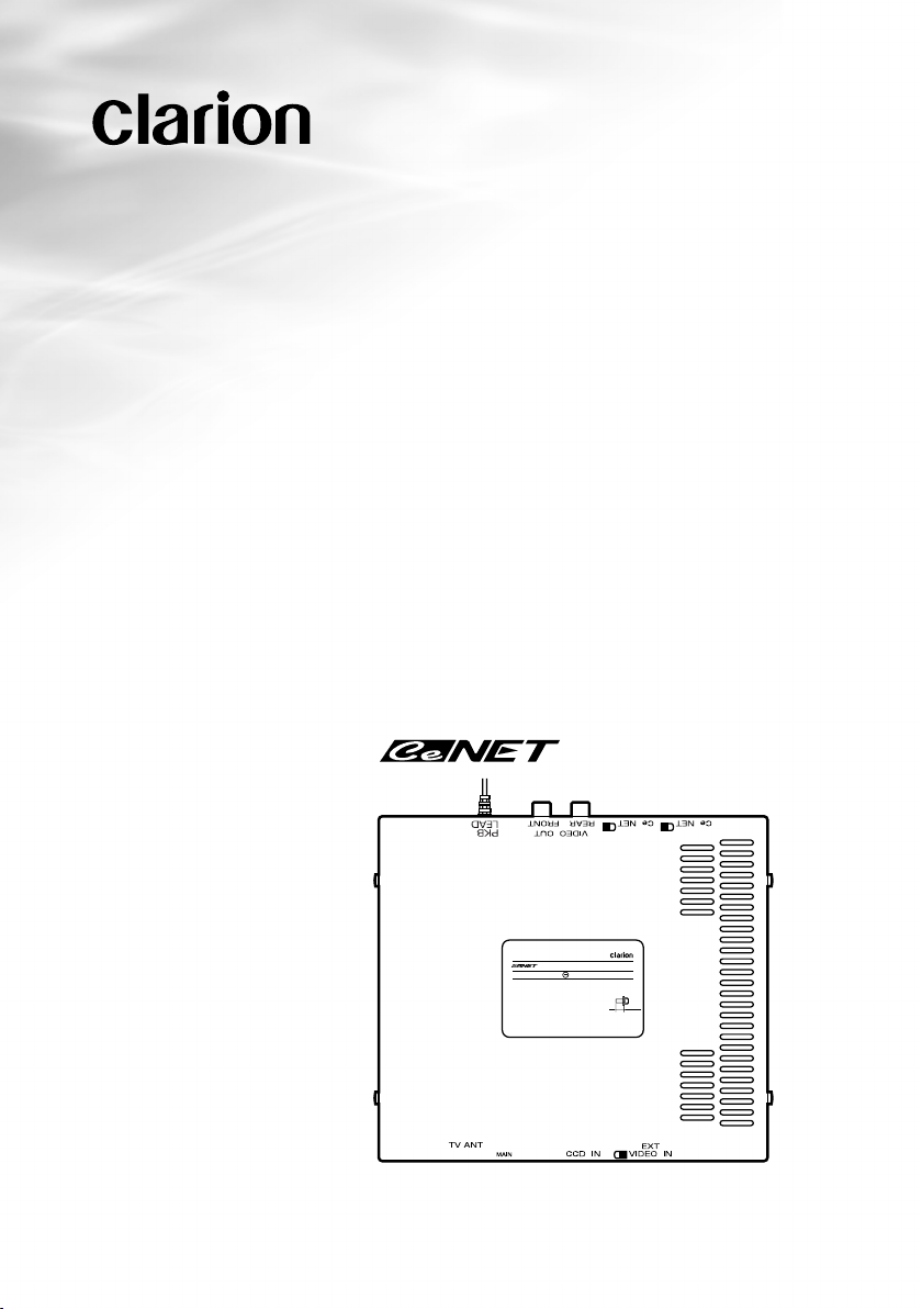
TTX7503z
CeNET TV TUNER (PAL/SECAM)
TUNER TV CeNET (PAL/SECAM)
CeNET-TV-TUNER (PAL/SECAM)
SINTONIZZATORE TV CeNET (PAL/SECAM)
NET TV-TUNER MET CeNET AANSLUITING (PAL/SECAM)
SINTONIZADOR DE TV CeNET (PAL/SECAM)
CeNET TV-TUNER (PAL/SECAM)
TUNER TV CeNET (PAL/SECAM)
MODEL
TT X7503z
VHF 45.75MHz-224.25MHz
UHF 471.25MHz-855.25MHz
Expand TV Tuner
12V GROUND
ISO
8mmMAX
Page 2

English
Thank you for purchasing this Clarion product.
• Please read this Owner’s manual & Installation manual in its entirety before proceeding
with wire connection and installation.
• After reading this manual, be sure to keep it in
a handy place (e.g., glove compartment).
If you sell the motor vehicle, please leave the
manual in it so that the new owner can use it.
• Read the contents of the enclosed warranty
card and keep it with this manual.
■
Contents
1. PRECAUTIONS ........................................4
2. PACKAGE CONTENTS ............................4
3. SET COUNTRIES LIST ............................5
4. SPECIFICATIONS .................................... 6
5. TROUBLESHOOTING..............................7
6. INSTALLATION.........................................8
7. CAUTIONS ON WIRING ...........................8
8. WIRING CONNECTIONS .........................9
Deutsch
Wir danken Ihnen für den Kauf dieses Clarion-
Produkts.
• Vor Einbau und Anschluß des Geräts
unbedingt die Einbau- und Betriebsanleitung
vollständig durchlesen.
• Bewahren Sie diese Betriebsanleitung nach
dem Durchlesen griffbereit an einem
geeigneten Ort (z.B. im Handschuhfach) auf.
Lassen Sie bitte diese Betriebsanleitung bei
einem Verkauf des Fahrzeugs für den
Nachbesitzer im Wagen.
• Lesen Sie die beiliegende Garantiekarte genau
durch und bewahren Sie sie zusammen mit
dem Handbuch auf.
■
Inhalt
1. ORSICHTSMASSNAHMEN ................. 17
V
2. LIEFERUMFANG ....................................17
3.
VORPROGRAMMIERTE LÄNDER-SENDERLISTE ....
4. TECHNISCHE DATEN ............................ 18
5. FEHLERSUCHE ..................................... 19
6. EINBAU ...................................................20
7.
VORSICHTSMASSNAHMEN BEIM ANSCHLIESSEN ..
8. KABELVERBINDUNGEN .......................22
17
21
Français
Nous vous remercions d’avoir acheté ce produit
Clarion.
• Veuillez lire entièrement le mode d’emploi et
le manuel d’installation avant de procéder aux
connexions et à l’installation.
• Après avoir lu ce mode d’emploi, prenez soin
de le conserver dans un endroit pratique (par
ex: la boîte à gants).
Si vous vendez votre véhicule à moteur,
laissez-y le manuel de façon que le nouveau
propriétaire puisse l’utiliser.
• Lisez le contenu de la carte de garantie comprise et conservez-la avec ce manuel.
■
Table des matières
1. PRECAUTIONS ......................................10
2. CONTENU DE L’EMBALLAGE ..............10
3. LISTE DES PAYS SÉLECTIONNÉS ......11
4. SPECIFICATIONS .................................. 12
5. RECHERCHE DE PANNES....................13
6. INSTALLATION.......................................14
7. PRECAUTIONS POUR L’INSTALLATION
DES CABLES .........................................15
8. CONNEXION DE CABLAGE..................16
2 TTX7503z
Italiano
Grazie per avere acquistato questo prodotto
Clarion.
• Si raccomanda di leggere completamente il
presente Manuale d'Istruzioni e Installazione
prima di procedere con i collegamenti e
l'installazione dell'apparecchio.
• Una volta letto, il presente manuale dev'essere
tenuto a portata di mano (per esempio nel
cassetto portaoggetti).
Se vendete la vostra vettura, consegnate
anche il manuale affinché il nuovo proprietario
lo possa utilizzare.
• Leggere il contenuto della scheda di garanzia
allegata, e conservarla sempre insieme al
manuale.
■
Indice
1. PRECAUZIONI........................................23
2. CONTENUTO DELLA CONFEZIONE.... 23
3. ELENCO DEI PAESI DA IMPOSTARE .. 24
4. SPECIFICHE ........................................... 25
5. RICERCA GUASTI ................................. 26
6. INSTALLAZIONE .................................... 27
7.
PRECAUZIONI RELATIVE AI CABLAGGI ...
8. COLLEGAMENTI....................................28
27
Page 3

English
1. PRECAUTIONS
• This equipment uses DC 12 V only. Do not
use this equipment on 24 V vehicles such
as large trucks.
• When driving, keep the TV tuner volume
down to a level where you can hear sounds
from outside the vehicle.
• If a problem occurs such as entry of a
foreign object, water gets into the tuner, or
it produces smoke or strange smells, stop
using the tuner immediately, and consult
your dealer.
■ Tuner Handling
• Disconnecting the cables while the system is
operating may cause a system breakdown.
Always turn off the power (ACC-OFF) before
you disconnect the cables.
• If the power supply to the system is stopped
due to battery replacement, etc., the details
you have entered into the microcomputer
memory may be erased and the settings may
return to the default settings. If this occurs,
enter your settings again.
INFORMATION FOR USERS:
CHANGES OR MODIFICATIONS TO THIS PRODUCT NOT APPROVED BY THE MANUFACTURER
WILL VOID THE WARRANTY.
■ Reception
• If your vehicle is outside the broadcast
transmission range, the radio waves will
become weak and reception will deteriorate.
UHF stations and regional broadcast stations
output a comparatively weak radio
transmission, so the reception conditions may
get worse while driving over a distance of only
a few kilometers.
• The screen image may be disturbed and output
noise due to train lines, high voltage power
lines and traffic signal lights.
• This equipment does not have a display
function, so the screen will be black during
driving.
2. PACKAGE CONTENTS
1. TV tuner unit (TTX7503z)
2. User’s Manual / Installation Manual .................................................................................................. 1
3. CeNET cable (2.5 m) ......................................................................................................................... 1
4. RCA video cable (2.5 m) ................................................................................................................... 1
5. Accessories Bag ................................................................................................................................ 1
6. PKB connection cable ....................................................................................................................... 1
4 TTX7503z
Page 4

English
3. SET COUNTRIES LIST
The TV area function can be used to set the following country areas.
No. Set Countries Display Title
ALBANIA
0
AUSTRIA
1
BELGIUM
2
BOSNIA I H
3
CZECH
4
DENMARK
5
FINLAND
6
FRANCE
7
GERMANY
8
GREECE
9
HUNGARY
10
ICELAND
11
IRELAND
12
ITALY
13
MOROCCO
14
NETHERLNDS
15
NORWAY
16
PORTUGAL
17
RUMANIA
18
RUSSIA
19
SLOVAKIA
20
SLOVENIA
21
SPAIN
22
SWEDEN
23
SWITZERLND
24
TURKEY
25
UK
26
Note:
When the TV receiving country is set to France.
If the TV receiving country has been set to France, the receivable channels range from L5 to L12, 21 to 69
TTX7503z 5
Page 5

English
4. SPECIFICATIONS
Reception channels: VHF CCIR 2 to 12 ch[CCIR “L” L5 to L12 ch (when receiving country has been
UHF CCIR 21 to 69 ch
Antenna input: 75 Ω unbalanced
voltage: 14.4 V
Grounding: Negative terminal grounding
Power consumption: 0.8 A or less
External dimensions: 178 mm (Width) ✕ 25 mm (Height) ✕ 160 mm (Depth)
Weight: 0.7 kg
6.4mm
* The specifications and design may be subject to change without prior notice due to improvements.
set to France.) ]
160mm
178mm
25mm
6 TTX7503z
Page 6

English
5. TROUBLESHOOTING
The following symptoms may not be the result of a breakdown, so perform the remedy suggested
below before contacting your Dealer for repairs.
Symptom Cause Remedy
No power
No image
Unclear image from
rear seat monitor
Image is unclear
Double or triple image
Image is spotty or
striped
Wiring is incomplete.
Parking brake is not engaged.
Image output for front and
rear is connected in reverse.
Poor reception
Poor reception
Electrical interference
Check the wiring method in the manual again,
then connect the wiring properly.
Check that the parking brake is engaged
completely.
Check the connection method in the manual
again, then connect the wiring properly.
The transmission may not be reaching you
properly because you are in a valley or the
shadow of a building. Check again at a location
where the transmission can reach you properly.
The image may be affected by transmission
reflected from
mountains or buildings. Change your location or
the reception
direction.
Reception may be affected by radio interference
from another
vehicle, a train, high voltage or neon signs.
Check your
reception again at another location.
TTX7503z 7
Page 7

English
6. INSTALLATION
CAUTION
• Disconnect the battery negative cable before connecting the wiring.
• If you are making holes in the vehicle body in order to install the unit, first confirm the
position of pipes, tanks and electrical wiring to avoid contact and interference.
• When installing the wiring for connection cords on a vehicle equipped with airbags, do
not install the wiring where it may affect the airbag system.
• Do not cover the ventilation holes and heat-radiating parts of the tuner.
■ Installation Using Screws
1. When using the installation holes at the sides
of the unit, use M4 ✕ 8 screws. Using screws
■ Installation Using Velcro Tape
1. Apply Velcro tape to the bottom surface of the
unit.
other than the specified screws may cause a
malfunction.
2. Attach the unit to the floor carpet beneath the
seat.
2. If you are going to drill holes in the dashboard,
make sure beforehand that there are no
harnesses behind the dashboard at that
position or nearby.
X
A
M
m
m
8
O
IS
z
H
5M
.2
5
5
z
-8
H
z
M
H
5
M
.2
5
4
2
.
2
1
-2
7
z
4
H
M
5
F
.7
H
U
D
45
N
F
U
H
V
O
GR
V
12
Expand TV Tuner
TTX7503z
L
E
D
O
M
Chassis
Max. 8 mm
7. CAUTIONS ON WIRING
Pay particular attention to the following points when laying out the cords.
• Keep the unit’s cables as far away as possible from the vehicle’s wiring bundles.
• Keep the unit’s RCA pin cord and the power cord separated as far as possible.
CAUTION
• When you have finished connecting the cords, secure them with clamps and insulating
tape for protection.
• Make sure that the connection cables will not get caught on burrs and edges of the metal
parts under the seat. It could damage the cables and cause noise from the unit.
• To assist safe driving, connect the parking brake connection terminal to the lead wire on
the lamp side of the parking brake lamp switch.
8 TTX7503z
Page 8

English
8. WIRING CONNECTIONS
Connect the unit as follows.
Notes:
*1 Connect the cable to the terminal of equipment (center unit) that is connected by connection cables
(CeNET cable) with the L-shaped terminals.
*2 Connection requires a CCA-389 conversion cord (RCA3P → mini DIN8P) which is sold separately.
*3 If you are connecting an antenna other than a 4 system diversity antenna, connect it to the MAIN
terminal on the far right.
*4 Connect the terminal to the lead wire on the lamp side of the parking brake lamp switch. After
connection, apply the parking brake, then check that the TV displays an image.
• If the PKB cable is not connected to the side brake, some units may not operate.
For connection of the monitor (such as the Clarion VRX633R, sold separately).
For connection of the rear seat monitor (sold separately).
To parking brake
Supplied PKB cable
Terminal (∗ 4) for connection
to parking brake.
For connection of the Clarion CD changer (sold separately) for CeNET use.
This unit (TTX7503z)
Antenna main (MAIN) terminal
For connection (∗ 3) of a Clarion
antenna such as ZCP-104 (sold
separately).
NAVI/CCD terminal.
Supplied CeNET cable (∗ 1)
For connection of a video appliance (∗ 2)
such as a handy camera (sold separately).
For connection of a Clarion CCD camera (sold separately).
*
For connection of VRX633R, connect the CCD camera to the
NAVI/CCD terminal of VRX633R.
Main unit (such as the Clarion VRX633R)
Supplied RCA video cable (∗ 1)
TTX7503z 9
Page 9

Clarion Co., Ltd.
2005/2 (D•K)
All Rights Reserved. Copyright in © 2005:Clarion Co., Ltd.
Printed in Japan / Imprimé au Japon / Gedruckt in Japan / Stampato in Giappone
Gedrukt in Japan / Impreso en Japón / Tryckt i Japan / Impresso no Japão
280-8225-00
ZT-4651E
 Loading...