


TTX7501z
Expanded TV T uner
English
Français
Español
English
English
Français
Español
CAUTION
• When you have finished connecting the cords, secure them with clamps and
insulating tape for protection.
• Make sure that the connection cables will not get caught on burrs and edges of the
metal parts under the seat. It could damage the cables and cause noise from the
unit.
• To assist safe driving, connect the parking brake connection terminal to the lead wire
on the lamp side of the parking brake lamp switch.
;;;
;
;;
;
;;
;;;
280-7099-10
Syntoniseur TV étend
Sintonizador de TV ampliado
TTX7501z
Owner’s Manual / Installation Manual
Manuel de l’utilisateur / Manuel d’installation
Manual del propietario / Manual de Instalación
PA CKAGE CONTENTS
2
1. TV tuner unit (TTX7501z)
2. User’s Manual / Installation Manual..................................................................... 1
3. CeNET cable (for connection to DRX8575z, 2.5 m)............................................ 1
4. Picture RCA cable (for connection to VMA8582, 2.5 m) ..................................... 1
5. Velcro tape........................................................................................................... 2
6. PKG connection cable......................................................................................... 1
FEATURES
3
INSTALLATION
6
CAUTION
• Disconnect the battery negative cable before connecting the wiring.
• If you are making holes in the vehicle body in order to install the unit, first confirm
the position of pipes, tanks and electrical wiring to avoid contact and interference.
• When installing the wiring for connection cords on a vehicle equipped with airbags,
do not install the wiring where it may affect the airbag system.
• Do not cover the ventilation holes and heat-radiating parts of the tuner.
■ Installation Using Velcro Tape
1. Apply Velcro tape to the bottom surface of the unit.
2. Attach the unit to the floor carpet beneath the seat.
M
O
D
E
L
T
T
X
7
5
0
E
1z
x
pa
n
d
T
V
T
u
n
er
1
2V
VHF
G
ROUN
54-
2
16M
D
UHF 4
T
Hz (2-
hi
s d
ev
70-
ice
13
foll
8
co
ch
06M
o
mp
wing
)
lie
Hz (14-
s
tw
in
wi
ter
th P
o
fer
co
69ch)
art
e
n
nd
c
1
in
e
5 o
it
c
,a
i
lud
o
f
nd
ns
th
in
(2
e F
g
: (1)
i
) T
n
C
terf
C
h
R
er
is
T
u
e
h
l
e
d
nc
is
s.
ev
e
Op
i
devic
t
c
h
e
at
er
m
at
m
u
e
i
ay
o
s
n i
t
m
ca
a
s
ay
c
u
s
ce
se
ub
not
p
un
je
t a
ct t
ca
de
n
o th
sir
y
in
u
e
se
e
d o
ter
har
p
fer
e
rat
e
m
n
ion
ce
f
u
l
.
re
IS
c
O
e
i
v
e
d
,
S
E
R
I
A
L
N
o
.
Z
T
4
6
2
0
B
8m
mM
A
X
C
la
ri
o
n
C
o.
M
,L
A
td
D
E
.
IN
J
A
P
A
N
2
8
6
9
2
1
4
-0
0
MODEL
TTX7501z
Expand TV Tuner
12V GROUND
VHF 54-216MHz (2-13ch)
UHF 470-806MHz (14-69ch)
This device complies with Part 15 of the FCC Rules. Operation is subject to the
following two conditions : (1) This device may not cause harmful
interference,and (2) This device must accept any interference received,
including interference that may cause undesired operation.
ISO
8mmMAX
Clarion Co.,Ltd.
SERIAL No.
ZT-4620B
MADE IN JAPAN
286-9214-00
• Please read this Owner’s manual & Installation man ual in its entirety before proceeding with wire connection
and installation.
• After reading this manual, be sure to keep it in a handy place (e.g., glove compartment).
If you sell the motor vehicle, please leave the manual in it so that the new owner can use it.
• Read the contents of the enclosed warranty card and keep it with this manual.
• Veuillez lire entièrement le mode d’emploi et le manuel d’installation avant de procéder aux conne xions et à
l’installation.
• Après avoir lu ce mode d’emploi, prenez soin de le conserver dans un endroit pratique (par ex: la boîte à
gants).
Si vous vendez votre véhicule à moteur, laissez-y le manuel de façon que le nouveau propriétaire puisse
l’utiliser.
• Lisez le contenu de la carte de garantie comprise et conservez-la avec ce manuel.
• Antes de pasar a la conexión de los cables y a la instalación, lea detenidamente este manual del usuario y de
instalación.
• Después de haber leído este manual, guárdelo a mano (p. ej., en la guantera).
Cuando venda su automóvil, deje en él el manual de instrucciones a fin de que pueda utilizarlo el nuevo
usuario.
• Lea el contenido de la tarjeta de garantía adjunta, y guárdela con este manual.
PRECAUTIONS
1
• This equipment uses DC 12 V only. Do not use this equipment on 24 V vehicles such as
large trucks.
• When driving, keep the TV tuner volume down to a level where you can hear sounds from
outside the vehicle.
• If a problem occurs such as entry of a foreign object, water gets into the tuner , or it pr oduces
smoke or strange smells, stop using the tuner immediately, and consult your dealer.
■ Tuner Handling
• Disconnecting the cables while the system is operating may cause a system breakdown. Always
turn off the power (ACC-OFF) before you disconnect the cables.
• If the power supply to the system is stopped due to battery replacement, etc., the details you have
entered into the microcomputer memory may be erased and the settings may return to the default
settings. If this occurs, enter your settings again.
■ Reception
• If your vehicle is outside the broadcast transmission range, the radio waves will become weak
and reception will deteriorate. UHF stations and regional broadcast stations output a compar atively
weak radio transmission, so the reception conditions may get w orse while driving over a distance
of only a few kilometers.
• The screen image may be disturbed and output noise due to train lines, high v oltage pow er lines
and traffic signal lights.
• This equipment does not have a display function, so the screen will be black during driving.
This equipment has been tested and found to comply with the limits for a Class B digital device ,
pursuant to Part 15 of the FCC Rules.
These limits are designed to provide reasonable protection a gainst harmful interference in a residential
installation.
This equipment generates, uses, and can radiate radio frequency energy and, if not installed and
used in accordance with the instructions, ma y cause harmful interf erence to radio communications.
However, there is no guarantee that interference will not occur in a particular installation.
If this equipment does cause harmful interference to radio or television reception, which can be
determined by turning the equipment off and on, the user is encouraged to consult the dealer or an
experienced radio/TV technician for help.
MODEL
TTX7501z
Expand TV Tuner
12V GROUND
VHF 54-216MHz (2-13ch)
UHF 470-806MHz (14-69ch)
This device complies with Part 15 of the FCC Rules. Operation is subject to the
following two conditions : (1) This device may not cause harmful
interference,and (2) This device must accept any interference received,
ISO
8mmMAX
Clarion Co.,Ltd.
SERIAL No.
ZT-4620B
INFORMATION FOR USERS:.
CHANGES OR MODIFICATIONS TO THIS PRODUCT NOT APPROVED BY THE MANUFACTURER WILL
VOID THE WARRANTY AND WILL VIOLATE FCC APPROVAL.
MADE IN JAPAN
286-9214-00
MODEL
T TX7501z
Expand TV Tuner
12V GROUND
VHF 54-216MHz (2-13ch)
This device complies with Part 15 of the FCC Rules. Operation is subject to the
following two conditions : (1) This device may not cause harmful
interference,and (2) This device must accept any interference received,
including interference that may cause undesired operation.
SERIAL No.
ZT-4620B
UHF 470-806MHz (14-69ch)
ISO
8mmMAX
Clarion Co.,Ltd.
MADE IN JAPAN
286-9214-00
• Compact size
The unit’s compact size of 7" (width) × 1" (height) × 3.9" (depth) permits flexibility in selecting the
installation location.
• CeNET connection
The center unit provides comprehensive control of the CeNET system.
• Rapid tuning in to your desired TV station
You can easily tune in to your favorite TV stations when travelling using preset tuning (6 stations
each for band TV1 and TV2) or manual tuning.
• Title and Memory Functions
You can enter into the memory up to 12 of your favorite broadcasting stations (a maximum of 10
characters for each name) such as TV stations. (6 stations each for band TV1 and TV2)
• Equipped with ima ge and audio input terminals, and a security camera connection terminal
You can connect your unit to an external video camera (∗) or Clarion security camera.
∗ Connection requires a Clarion conversion cord CCA-389 (RCA3P → mini DIN 8P) which is sold
separately.
• Equipped with RCA gold-plated image output terminal
The image output terminal is a non-magnetic gold-plated terminal to prevent signal deterioration
and aged deterioration.
SPECIFICATIONS
4
Reception channels: VHF 54 - 216 MHz (2 -13 channels)
UHF 470 - 806 MHz (14 - 69 channels)
Antenna input: 75 Ω unbalanced
voltage: 14.4 V
Grounding: Negative terminal grounding
Power consumption: 0.4 A or less
External dimensions: 7" (Width) × 1" (Height) × 3.9" (Depth)
[178 mm (Width) × 25 mm (Height) × 100 mm(Depth)]
Weight: 1.1 lb. (0.5 kg)
3.9" (100mm)
7" (178mm)
0.26" (6.6mm)
1" (25mm)
∗ The specifications and design ma y be subject to change without prior notice due to improvements.
TROUBLESHOO TING
5
The following symptoms ma y not be the result of a breakdown, so perform the remedy suggested
below before contacting your Dealer for repairs.
Symptom
No power
No image
Unclear image from
rear seat monitor
Image is unclear
Double or triple image
Image is spotty or
striped
Cause
Wiring is incomplete.
Parking brake is not engaged.
Image output for front and rear
is connected in reverse.
Poor reception
Poor reception
Electrical interference
Remedy
Check the wiring method in the manual again,
then connect the wiring properly.
Check that the parking brake is engaged
completely.
Check the connection method in the manual
again, then connect the wiring properly.
The transmission may not be reaching you
properly because you are in a valley or the
shadow of a building. Check again at a location
where the transmission can reach you properly.
The image may be affected by transmission
reflected from mountains or buildings. Change
your location or the reception direction.
Reception may be affected by radio interference
from another vehicle, a train, high voltage or
neon signs. Check your reception again at
another location.
■ Installation Using Screws
1. When using the installation holes at the sides of the
unit, use M4 × 8 screws. Using screws other than the
specified screws may cause a malfunction.
2. If you are going to dr ill holes in the dashboard, make
sure beforehand that there are no harnesses behind
the dashboard at that position or nearby.
CAUTIONS ON WIRING
7
Pay particular attention to the following points when laying out the cords.
• Keep the unit's cables as far away as possible from the vehicle's wiring bundles.
• Keep the unit's RCA pin cord and the power cord separated as far as possible.
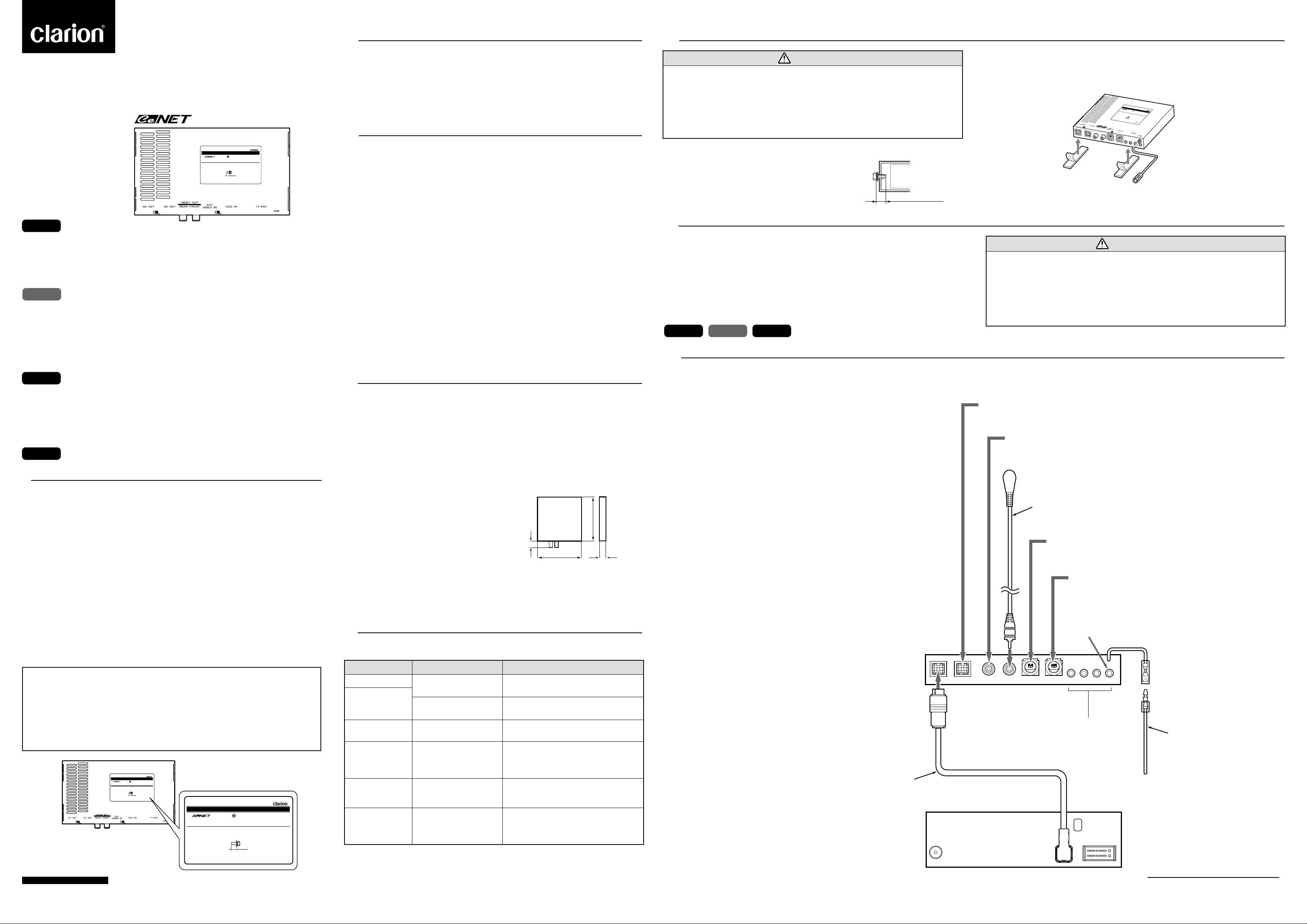
WIRING CONNECTIONS / CONNEXION DE CABLA GE / CONEXIÓN DEL CABLEADO
8
Connect the unit as follows.
Raccordez l’unité de la manière suivante.
Conecte la unidad en la forma siguiente:
Notes:
∗1 Connect the cable to the terminal of equipment (center unit, monitor) that is
connected by connection cables (CeNET cable, RCA cable) with the L-shaped
terminals.
∗2 Connection requires a CCA-389 conversion cord (RCA3P → mini DIN8P) which
is sold separately.
∗3 If you are connecting an antenna other than a 4 system diversity antenna, connect
it to the MAIN terminal on the far right.
∗4 Connect the terminal to the lead wire on the lamp side of the parking brake lamp
switch. After connection, apply the parking brake, then chec k that the TV displa ys
an image.
• If the PKG cable is not connected to the side brake, some units may not operate.
Notes:
∗1 Raccordez le câble à la borne de l’équipement (unité centrale, moniteur), laquelle
est reliée par les câbles de connexion (câble CeNET, câble RCA) aux bornes en
forme de “L”.
∗2 La connexion nécessite un câble de con version CCA-389 (RCA3P → mini DIN8P)
vendu séparément.
∗3 Si vous utilisez une antenne autre qu’une antenne de diversité pour 4 systèmes ,
raccordez l’antenne à la borne MAIN située à l’extrémité droite.
∗4 Raccordez la borne au câble conducteur situé côté ampoule du contacteur de
témoin de frein de stationnement. Après le branchement, appliquez le frein de
stationnement, puis assurez-vous qu’une image apparaît à l’écran du téléviseur .
• If the PKG cable is not connected to the side brake, some units may not operate.
Notas:
∗1 Conecte el cable al terminal del equipo (unidad central, monitor) que
está conectado mediante los cables de conexión correspondientes
(cable CeNET, cable RCA) con los terminales en forma de L.
∗2 Para conectar se necesita un cable CCA-389 de conversión (RCA →
mini DIN8P), que es vendido separadamente.
∗3 Si está conectando una antena diferente de la antena de diversidad de
sistema 4, conéctela al terminal PRINCIPAL (MAIN), situado en el
extremo derecho.
∗4 Conecte el terminal al cable principal en el lado de la lámpara del
interruptor del indicador luminoso de freno de estacionamiento. Después
de haber efectuado la conexión, aplique el freno de estacionamiento
(aparcamiento), y enseguida compruebe que la TV muestra
efectivamente una imagen.
• Si el cable PKG no está conectado -en la forma indicada- con el
terminal del freno de estacionamiento, es posible que algunas
unidades no funcionen.
Supplied CeNET cable (∗ 1)
Câble CeNET fourni avec l'équipement (∗ 1)
Cable CeNET (∗ 1), suministrado.
Chassis
Max. 5/16" (8mm)
For connection of the Clarion CD changer (sold separately) for CeNET use.
Pour la connexion du changeur de CD Clarion (vendu séparément) pour l'utilisation de CeNET.
Para la conexión del cambiador Clarion de CD (vendido separadamente) para la utilización CeNET.
For connection of the rear seat monitor (sold separately).
Pour la connexion du moniteur de siège arrière (vendu séparément).
Para la conexión del monitor (pantalla) del asiento trasero (vendido separadamente).
For connection of the monitor (such as the Clarion VMA8582, sold separately).
Pour la connexion du moniteur (tel que le VMA8582 Clarion, vendu séparément).
Para la conexión del monitor (tal como el modelo Clarion VMA8582, vendido separadamente).
Supplied image RCA cable (
Câble RCA image (
Cable RCA de imagen, suministrado. (
For connection of a video appliance (∗ 2) such as a handy camera (sold separately).
Pour la connexion d'un appareil vidéo (∗ 2) tel qu'une caméra vidéo (vendue séparément).
Para la conexión de un aparato de vídeo (∗ 2), como una cámara manual (vendida separadamente).
For connection of a Clarion security camera (sold separately).
Pour la connexion d'une caméra de sécurité Clarion (vendue séparément).
Para conectar una cámara Clarion de seguridad (vendida separadamente).
Antenna MAIN terminal
Borne d'antenne MAIN
Terminal PRINCIPAL (MAIN) de antena.
SOURCE UNIT(TTX7501z)
UNITE SOURCE (TTX7501z)
UNIDAD FUENTE (TTX7501z)
For connection (∗ 3) of a Clarion antenna such as ZCB-303 (sold separately).
Pour la connexion (
éparément).
Para la conexión (
(vendida separadamente).
∗
3) d'une antenne Clarion telle que ZCB-303 (vendue s
∗
3) de una antena Clarion, como el modelo ZCB-303
CENTER UNIT(DRX8575z)
UNITE CENTRALE (DRX8575z)
UNIDAD CENTRAL (DRX8575z)
∗
1)
∗
1) fourni avec l'équipement
∗
1)
To parking brake
Vers le frein de stationnement
Al freno de aparcamiento.
Terminal (∗ 4) for connection to parking brake.
Borne (∗ 4) pour la connexion au frein de stationnement.
Terminal (∗ 4) para conectar el freno de estacionamiento
(aparcamiento).
Supplied PKG cable
Câble PKG fourni avec l'équipement
Cable PKG, suministrado.
Clarion Co,. Ltd.
All Rights Reserved. Copyright © 1999: Clarion Co., Ltd.
Printed in Japan 1999/3 (T.K) ZT-4620B
 Loading...