

Page 1
'n
l,j
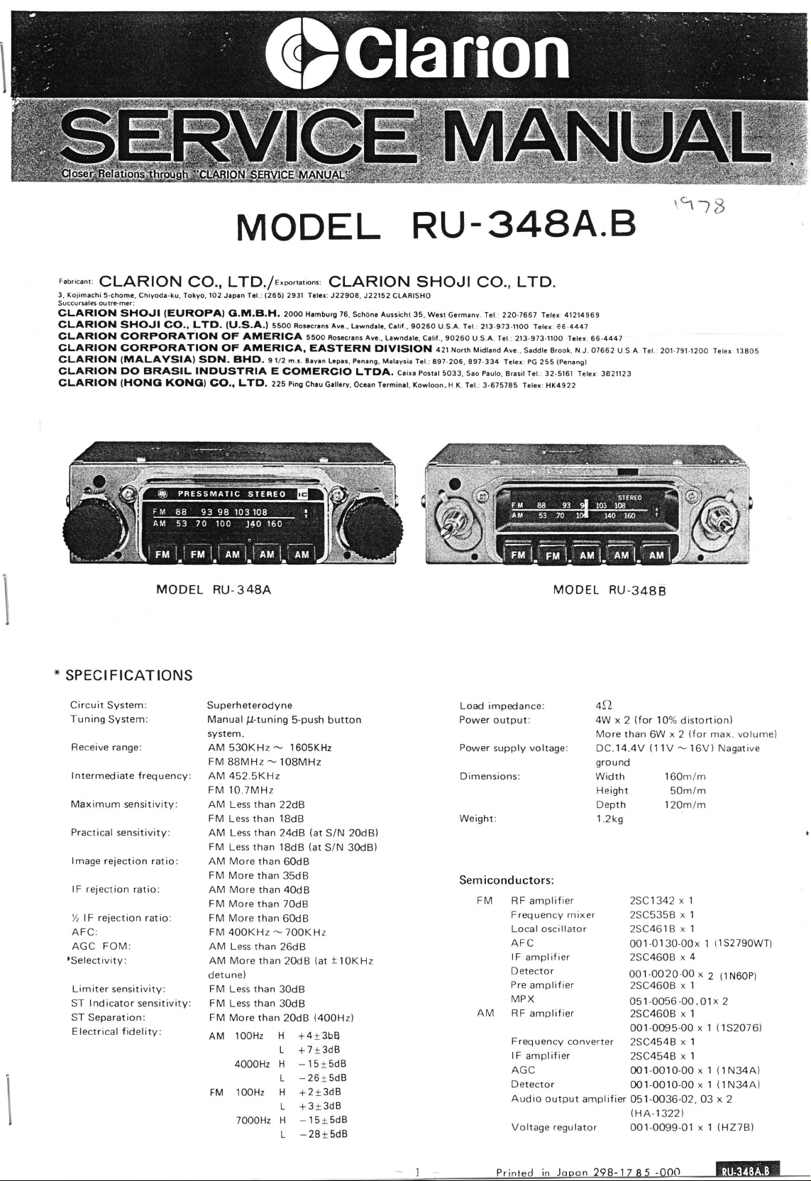
MODEL
r"o,i."nr,
Ql_;{RION
3, Koiimachi
Succursl6 outru-mer:
GLARION SHOJI
5-chome. Chiyoda-ku, Tokyo.102 J.p.n l.l.:
CLARION SHOJI
CLARION CORPORATION OF AilIERIGA 55oo
CLARION CORPORATION OF AMERICA. EASTERN
CLARION
CLARION
CLARION
(MALAYSIAI
DC) BRASIL INDUSTRIA E
(HONG
CO., LTD./e,m,r"tion., CLARION SHOJI
(EURCIPAI
CO.,
KONGI
MODEL
G.M.B.H.
LTO.
{U.S.A.I
SON. BHO. 9l/2 m.s.
LTD. 225 Ping
CO,,
RU.3484
2931 TGl.x:
{2651
2OOO H.mbu.g 76.
55oO Ro!.cr.os
B.y.n
COMERCIO
Chru
J22908. J22152 CLAnISHO
Sch6n. Aussicht 35.
Avc.. Lrwnd.t..
nosacrlns Avc..
t.pts, P.n.ng. Mrlaysia Tcr.:697-206.897-334
LTOA. c.ira Postlt
G.tt.ry, Occ.n T..min.t.
RU-348A.E}
LTD.
CO.,
Wort Gcrmenv. r.t
C.tif.. 90260 U.S.A. Tct.:
L.wndste.
DIVISION
c.tit..
421
5033. sao
Kowtoon. H
213-973-fiOO
90260
U.s.A. TGt :
Norrh M.dtand ave..
pauto.
j
Tct.
K
3-675785 Tolex: HK492
reter 41214969
2zo.r66t
T.tex
2t3-973rloo
saddte Brook. N J. 07662
Tctex: PG 255
B.asit r.t.:
32-sl6l reter: 3821123
€6.4447
T6tex
66-4447
(Pcnans)
2
MODEL
u s A r.t
RU.348B
2ol-7el.12oo rct€x 138os
SPECIFICATIONS
Circuit SVstem:
Tuning
System:
Receive range:
I ntermediate
Maximum
Practical
lmage
lF rejection
lF
%
AFC:
AGC
rSelectivity:
Limiter sensitivity:
ST I ndicator
ST
Separation:
Electrical
frequency:
sensitivity:
sensitivity:
rejection ratio:
ratio:
rejection
ratio:
FOM:
sensitivity:
fidelity:
Superheterodyne
p-tuning
Manual
system.
AM
53OKHz
FM
88MHz
AM 452.5KH2
s-push button
1605KHz
-
108MHz
-
FM 10.7MHz
AM Less than
FM
Lessthan
AM Less
FM
Less than
AM More than
FM More
AM More than
FM More than 70dB
FM
More than
FM 4O0KHz
AM Less than
More
AM
detune)
FM Less than
FM
Less than
FM More than
100H2
AM
22dB
18dB
than
24dB
'l8dB
60dB
than
35dB
4OdB
60dB
700KHz
-
26dB
than 2OdB
30dB
30dB
20dB
H
L
4000H2
H
L
FM
100H2
H
L +3+3dB
7000H2
H
L
(at
S/N 2OdB)
(at
S/N 30dB)
(at
t
{400H2)
+4r3bB
+7+3dB
-15+sdB
-26t5dB
+2+3dB
-15tsdB
-28tsdB
IOKHz
impedance:
Load
Power
output:
Power
Dimensions:
Weight:
supply
voltage
Semiconductors:
FM
RF amplifier
Frequency mixer
Local oscillator
AFC
I F
amplif ier
etector
D
Pre
amplif
MPX
AM
RF amplifier
Frequency
lF
amplif
AGC
Detector
Audio output
Voltage
ier
converter
ier
amplifier
regu lator
4f2,
(for
4W x
More
DC.14.4V
gro
u nd
width
H eight
Depth
1.2k9
2
than
6W
{11V
2SC1342
2SC535B
2SC461B
.0130-00x
oo1
2SC46OB
1-O020'00x
00
2SC460B
10%
x
160m/m
50m/m
120m/m
051-0O56-00.01x 2
2SC460B
O01-O095-O0
2SC454B
2SC454B
0O1-00'10-00
0O1-OOIO-OO
051-0036-02. O3
(HA-r
322)
OO1-O099-Ol x 1 {H278)
distortion)
(f
or max. volume)
2
16V) Nagative
-
x
1
x
1
x 1
(152790wT)
1
4
x
(tN6OP)
2
x
1
x 1
(152O76)
x 1
x
1
x 1
(1N34A)
x
1
(1N34A)
x
1
x
2
l P,int"d
.
in Jooon 298-17 Rs
-oott
lilllllll'I
Page 2
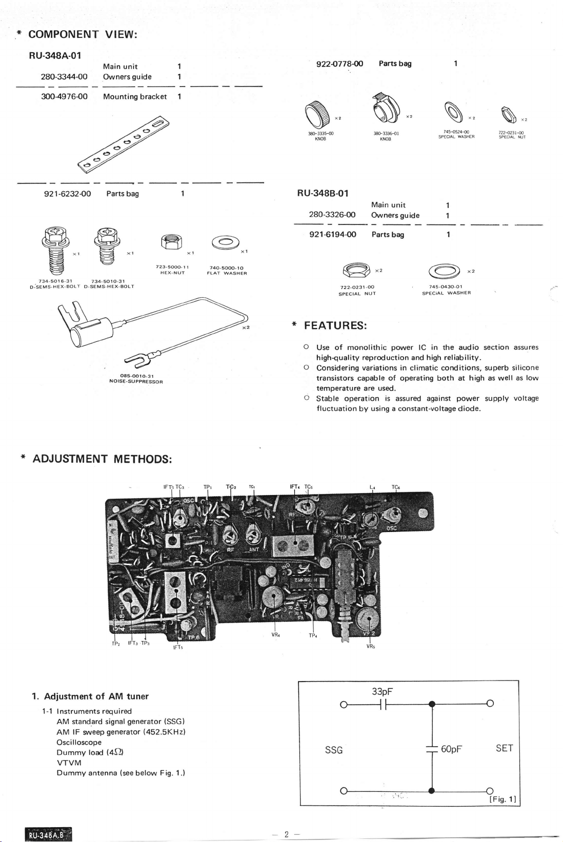
*
COMPONENT
VIEW:
RU-348A-01
Main unit
280-334400
Owners
guide
3004976{)0 Mounting bracket 1
Parts
921-6232-00
,A
fLal]l
@@€]€)",
734-5016,3t
jseus,sex-eour
o
E[
ev
El
\J
,'
734-50tO-3t
D-sEMs-HEX-BoLT
bag
(_<in
xi
vl
v
oa5-@ro-3t
NOISE.SUPPAESSOR
1
1
723,so@-tl
HEX_NUT
x,
74o-so@_lo
FLAT
WASBEF
922-O778fi
@
*333m
KNOE
RU-3488-01
280-3326-00
921€194{P
722-0231-OO
SPECIAL
*
FEATURES:
o
o
of monolithic
Use
highquality
Considering
transistors capable of operating both at
temperature are used.
o
operation
Stable
fluctuation
Partsbag
*33Hl
KNOB
Main
unit
Ownersguide
Parts
bag
NUT
power
reproduction
variations in climatic conditions, superb silicone
using
by
and
is
assured
a constant-voltage diode.
N
74ffi.{
sP€OAL
@-,
745-0430-Ot
WASHER
SPECiAL
in
lC
the audio section
high reliability.
against
WASER
high as
power
well
supply
assures
low
as
voltage
*
ADJUSTMENT
1.
Adjustment of AM
1-1 lnstruments required
stand€rd signal
AM
lF
AM
Oscilloscope
Dummy
VTVM
Dummy
siveep
load
antenna
METHODS:
tuner
generator
(see
(452.5KH2)
below
generator
(4Ql
(SSG)
F ig.
o---l
1 .l
-2-
Fig. 1l
Page 3
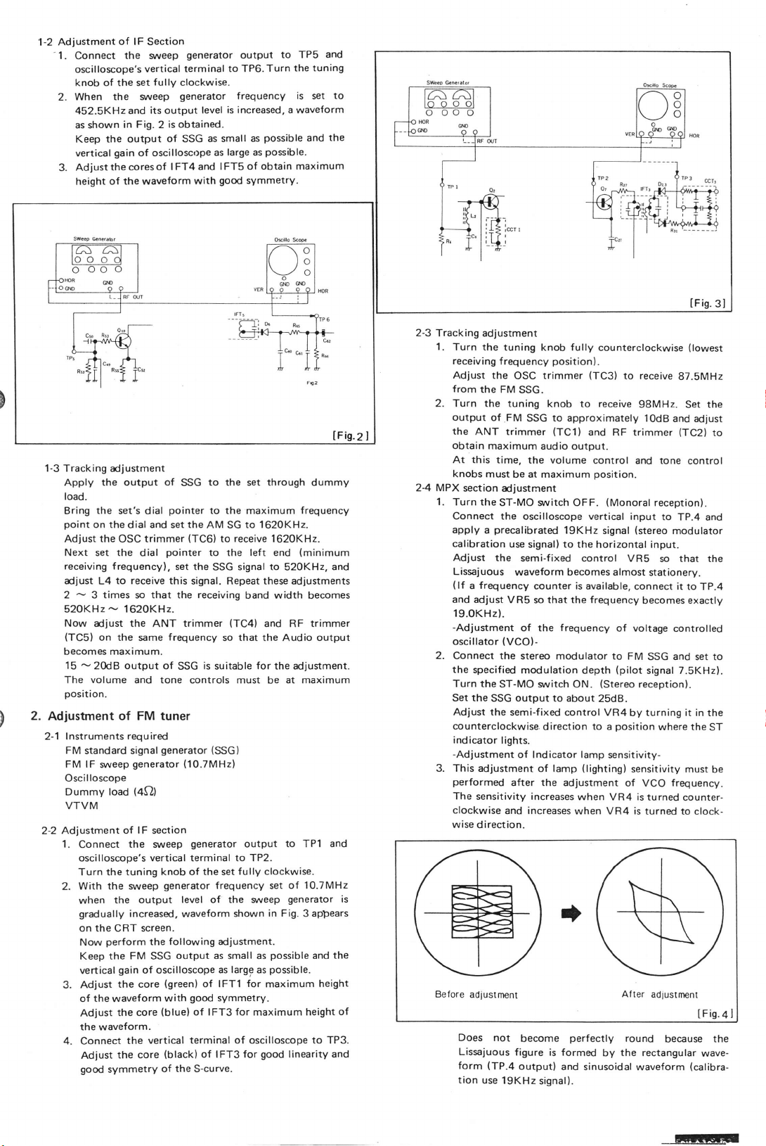
Adjustment
1-2
-1.
Connect
oscilloscope's
knob of the set
When the sweep
2.
452.5KH2
as shown
Keep the
gain
vertical
the
Adiust
3.
1-3 Tracking
of the waveform
height
adjustment
Apply the output of
load-
the
Bring
point
on the
Adiust the OSC trimmer
Next set the
receiving frequencyl,
adjust
L4
2
3 times
-
52OKHz
Now adjust the
(TC5)
becomes maximum.
15
The
position.
2.
Adjustment of FM
2-1 lnstruments
FM
FM
Oscilloscope
Dummy load
VTVM
Adjustment
2-2
1.
2.
-
on the same
20dB output of
-
volume
standard signal
lF
sreep
Connect
oscilloscope's vertical terminal to TP2.
Turn the tuning
With the sweep
the output
when
gradually
on the CRT screen.
perform
Now
Keep the FM SSG
vertical
3. Adjust
the
of
waveform
Adjust
the waveform.
4.
Connect
Adiust
good
symmetry
of lF
Section
the sweep
vertical
generator
terminal to TP6.
fully
clockwise.
generator
is increased, a waveform
and its output
in Fig-
2
output
oscillosc()pe
of
of I FT4 and
cores
set's dial
dial and set
dial
to receive this
that the receiving
so
1620KH2.
ANT
level
is obtained.
of
as small
SSG
SSG
pointer
pointer
set the
trimmer
frequency
SSG
large
as
lFT5 of obtain
good
with
to the set through dummy
the
to
the
AM SG
(TC6l
to
receive
to the left end
SSG
signal. Repeat these adiustments
(TC4)
so that the
is
suitable
and tone controls must
tuner
required
generator
generator
(4Sr)
of lF
section
the
sweep
knob of the set
generator
increased,
following
the
gain
of oscilloscope
the core
(green)
with
(blue)
core
the
vertical terminal of oscilloscope
the
the core
(black)
of the s-curve.
(SSG)
(10.7MH2)
generator
level
of
waveform
output as
of lFTl
good
of lFT3 for
of lFT3 for
frequency set
the sareep
shown
adjustment.
small as
large
as
symmetry.
output
f requency
as
symmetry.
maximum
Turn
possible
possible.
as
the tuning
is
set
and
maximum
frequency
TPS and
to
to 1620KH2.
162OKHz-
(minimum
signal to
520KHz,
band width
becomes
and RF trimmer
output
Audio
for
adiustment.
the
at maximum
be
output to TPI and
fully clockwise.
of 10.7MHz
generator
in Fig.
as
for
maximum
maximum
possible
possible.
appears
3
and the
height
height
to
good
linearity and
to
the
and
TP3.
2-3
Tracking adjustment
1.
Turn the
receiving
Adjust the
from
2. furn the
output
the
obtain
At this time,
knobs
2-4 MPX
1.
Turn the
Connect the
apply
calibration
Adiust
Lissajuous
(
lf
and adiust
19.OKHz).
-Adiustment
oscillator
2. Connect the
the
Turn the
Set the
Adjust the
counterclockwise.
indicator
-Adjustment
3. This
performed
The
clockwise
wise direction.
is
tuning knob fully
f requency
OSC trimmer
the FM
SSG.
tuning knob
of FM
SSG
ANT trimmer
maximum
audio output.
the volume
must be at maximum
section adjustrnent
ST-MO witch OFF.
oscilloscope vertical input
precalibrated
a
use
signal)
the
semi-f
waveform becomes almost
frequency
a
counter is available,
VR5 so that the frequency
of the
(vco)-
specified
adjustment of lamp
sensitivity increases
stereo modulator to
modulation
ST-MO sryitch ON.
SSG output to about
semi-fixed control VR4
lights.
of lndicator lamp
after the adjustment
and increases
position).
ro
(TC1)
counterclockwise
(TC3)
receive
to
approximately lOdB
and RF trimmer
control and tone
position.
(Monoral
19KHz
signal
to
the horizontal input.
ixed
control VR5
frequency
depth
(Stereo
25d8.
direction to a
sensitivity-
(lighting)
when
VR4 is turned
when VR4 is turned
receive
to
98MHz.
(stereo
connect it to
becomes
of voltage controlled
FM
(pilot
receptionl.
by turning it in the
position
sensitivity must
of VCO frequency.
(lowest
87.5MHz
the
Set
and adjust
(TC2)
control
reception).
to
TP.4 and
modulator
so that the
stationery.
TP.4
exactly
and
SSG
signal 7.5KHz).
set to
where the
counter-
to clock-
ST
to
be
t
Betore
adjustrnent
of
Does not
Lissajuous
(TP.4
form
tion
use
19KHz
become
figure
outputl and
perfectly
is formed
signal).
Alter
adiustrnent
round
the
by
sinusoidal waveform
because
rectangular
lFis.ql
the
wave-
(calibra-
ffi
Page 4
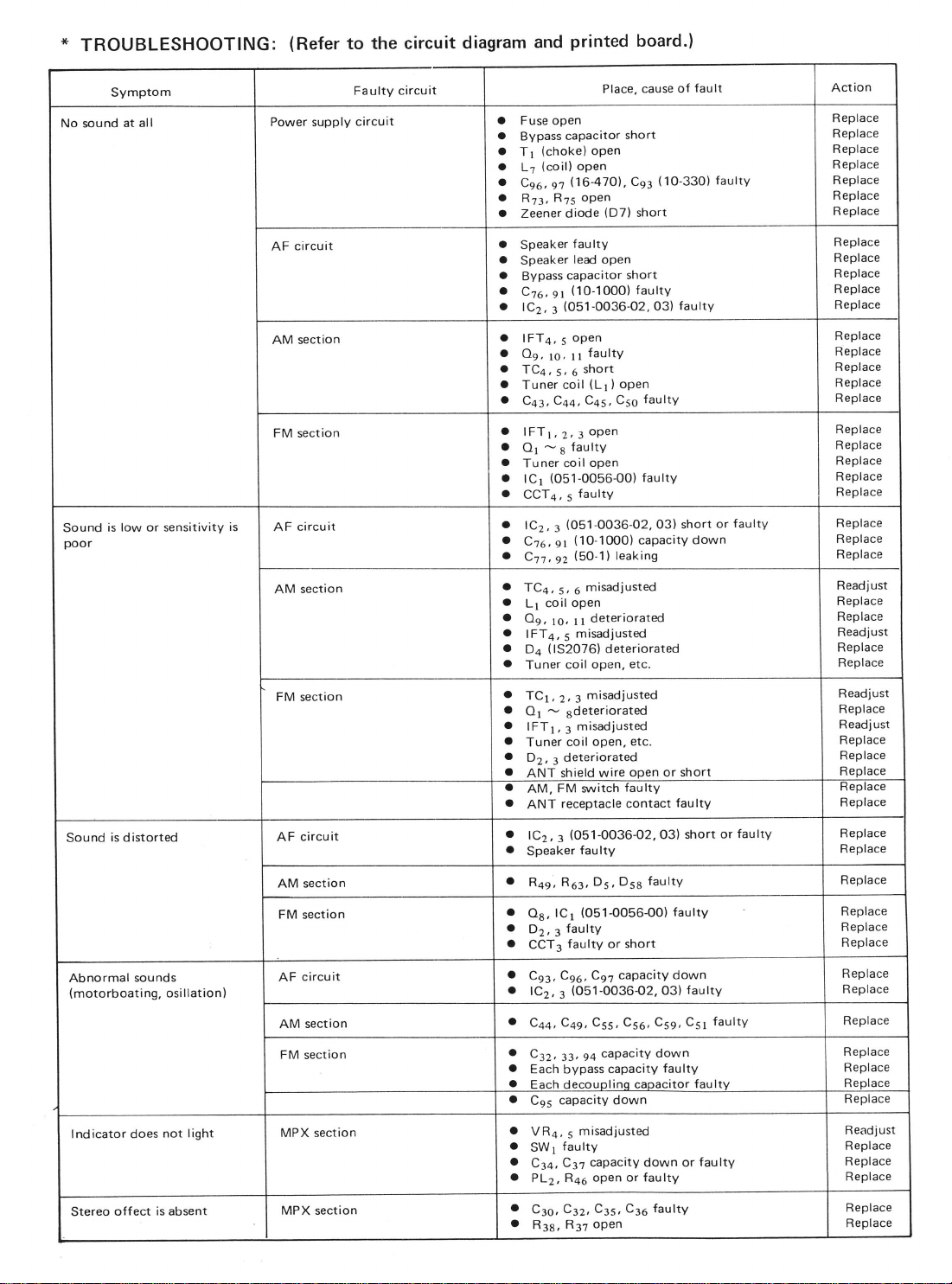
*
TROUBLESHOOTING:
(Refer
to the circuit
diagram
and
printed
board.)
Symptom
No sound
Sound
poor
Sound
Abnormal
(motorboating,
at all
is low or sensitivity
is
distorted
sounds
osillation)
is
Power
supply
circuit
AF
AM section
FM section
circuit
AF
AM section
FM section
AF circuit
section
AM
FM
section
circuit
AF
AM section
FM section
Faulty
circuit
circuit
cause of
Place,
a
Fuse open
a
o
a
o
O
ta
a
o
o
o
o
o
o
o
o
o
O
a
o
o
a
I
o
o
3
o
o
o
.
o
I
a
o
o
'
a
o
a
I
a
3
o
o
o
a
a
o
'
a
O
o
capacitor
Bypass
(choke)
T1
(coil)
L.t
Cso,
n6-470l,
n
R75
Rr:.
Zeener diode
Speaker
Speaker
capacitor
Bypass
(10-lOOO)
Ctd,
e1
(051-0036-02,
tC2,
r
lFT4,5
Os,
ro, 1l
TCa,
s,6
coil
Tuner
Ccq, Cqs,
C+r,
lFT1,2,3open
faultY
O1
s
-
Tuner coil
(051-0056-o0)
lcr
CCTa,
5
(051-0036-02,
lCz
3
Cto
el
qz
Ctt
TC+,
5, 6
open
coil
Lr
Oq,
to, ll
lFTq,
5
(1520761
Dq
coil open,
Tuner
TCr,
2,
Ot
Sdeteriorated
-
lFTr,
3
coil open,
Tuner
Dz,
deteriorated
3
ANT shield wire
FM
AM,
receptacle contact
ANT
(O51-0036{2,03)
lCz,3
Speaker
R+e, Rr:,
lCr
Os,
faulty
Dz,
g
faulty or short
CCT:
Cqo, C9?
Cgr,
(051-0036O2,
lC2,
3
C+s, Css, Cso,
Cqq,
Csz,
33,
Each
bypass
Fach clecouolino caoacitor faultv
capacity down
C9s
short
open
open
oPen
(D7)
,
Ce3
short
faulty
lead open
short
faulty
open
faulty
short
(Ll
open
)
C5s
open
faultY
(10-10OO)
(5O-11
misad.iusted
misadjusted
misadjusted
3
misadjusted
s
capacity
leaking
deteriorated
deteriorated
etc.
etc.
ooen
,atch taulty
faulty
Ds, D5s
(051-0056-O0)
capacity down
capacity down
94
capacity
faultY
faulty
faultY
fault
(1O-330)
faultY
O3)
O3) short
down
or short
faulty
short
faultY
faulty
03)
Css, C51
faulty
faultv
or
or
faultY
faulty
faultv
Action
Replace
Replace
Replace
Replace
Replace
Replace
Replace
Replace
Replace
Replace
Replace
Replace
Replace
Replace
Replace
Replace
Replace
Replace
Replace
Replace
Replace
Replace
Replace
Replace
Replace
Read.iust
Replace
Replace
Readjust
Replace
Replace
Readjust
Replace
R eadj usl
Replace
Replace
Replace
Heprace
Replace
Replace
Replace
Replace
Replace
Replace
Replace
Replace
Replace
Replace
Replace
Replace
Renlace
Replace
lndicator does
Stereo offect is absent
not light
MPX section
MPX section
3
VR+,
a
SWr
o
C:+,
I
PLz, R46
o
Cso,
I
Rea,
misadjusted
s
faulty
capacity down or
Ca?
Caz, Crs,
R37
oPen
oPen
or faultY
C36 faulty
faultY
Readj ust
Replace
Replace
Replace
Replace
Replace
Page 5

EXPLODED
*
@Main
section
VIEW:
+/A
"r\,
l"
("'
\,1
\,Q
ae
-\
!*
,o
05
)
d
F
,F
----..
{
f
-a)
4-
t
/
o
N...
JI
\
-\\
@r\')
=@\
/
\.
Page 6

PARTS
*
OMain
REF.NO.
section
3 /O-2994-Ol
1
37()-28O3-Ol
372-2751-OO
2
372-2743-OO
37 1 - 2590-Ot
3
377-O1
4
722-0231-OO
5 745-0250-00
6 330-5341
7 308-086s-OO
374-0693-OO
I
374-069r -OO
I
345-2644-00
to
745-O220-OO
11
745-0430-00
12
375-0530-02
t3
345-2497-00
14 01 7-0308-00
376-O799-OO
16
376-O796-OO
17
347-0523-01
18 092-051 5-00
19
1
3
:286-3gos-ob
20
i286-3897-OO
21
'28G8COa-q)
l2at.sr-oo
22
311-089$00
LIST:
PART NO
53-OO
-O0
0-0860-00
DESCRIPTION
Escutcheon
prate
Diar
plate
Trim
Dial
support RU-34a8
Special
nut 2
Special washer
Pressed
Front
bacK
Rubber
pan
cover 1
prare
part
Special washer
Special washer
Pilotlamp
Rubber
accessory
part
Pilotlamp
pointor
Diat
part
Paper
Antenna
receptacle
Upper case
Setolate
.
setprate
Lower case
EU_3i361
FU-3i34
RU-344A
RU-34AA
RU-34a8
FU:3i33
RU-3484
RU-3z+AB
FU:8181,
P.C.S
1
1
1
a
2
1
1
2
1
1
1
1
1
1
1
1
1
1
1
REF. NO.
285-0656-OO
23
295:0513-90_,
24 335-0580-O0
PART NO
Guide label 1
Molded
25 330-5248-O0 ,Presseb
26 oo9-061 7-OO
27
28s-064s-00
28
o1 2-3484-00
0o4-!59+Ql
29
342-O 1
30
31 01
07-OO
382-O1 06-OO
49-O0
3-31
32 330-5002-00
33
01 7-0306-01
34 070-0927-01
35 335-0635-06
36 05 1
37
-0036-02
1
3
3-0936-00
38 944-0459-00
39 099-4547-00
850- 1 924-OO
40
850- 1 926-OO
4'l
851-2171-00
42 1
43
44 725-01
20-0020-00
850- 1 895-OO
850- 1
925-OO
82-00
45 7 1 4-3006-8
46 73 1
47
48
-
3006-80
01 0- 1
686-00
099-4548-OO
49 099 4549-OO
1
Choke
Guide label 1
Variable resistor
Trimmer
Burton
Switch
Pressed
Pilotlamp
Pilotlamp
Molded
tc
Heat
Filter
PWB
A-read
SP-lead
Fuse
A-read
Plate nut
Machine
Tap tisht
Coil
PWB
PWB
DESCRIPTION
part
part
f,U:li8i
part
socket 1
part
sink 1
assembly 1
ES:8X36,
(2A)
FU:liB6
screw(M3
(M3x6)
x6l
P.C.S
1
I
1
1
2
1
I
1
4
4
22
@Elactrird
t
c{krn
llltm
Page 7

PARTS
*
OEloctrical
LIST:
rcction
REF, NO PART NO
1
1
02-
Q'
Qz
o:
342-00 Transistor
r 02-0535-02
102-0461
-02
DESCRIPTION
Transistor
Transistor
o!.1.9 1 02-0460-02 Transistor
Oro.
lCr
lCz.r
Dr 001
Dz.t
D4
Ds.
D, 001
TCr z004- 1
TC: 004. 1 502-01
TC, 004-1504-00 |
TCs
CCTr.z 050-0030-00
ccr3
ccTl
VRo.i 01 2-3394-00
Tr
Lr 0
102-0454-02
r t
-0056-oo
osl
051.OO36-02
001
o1
o3
-0
r
30-00 Diode
-0020-oo
001-0095-00
001-001 0-00 Diode
u
-0099-01
496-00
Transistor
rc
rc
Diode
Diode
Diode
Trimmer
Trimmer
Trimmer
1 498-00
004-
e
Trimme r 2
Component
050-001 0-00 Component circuil
s
050-005
1
Component circuit
-00
Variable resistor
009-0617-00: Choke
1
0-0930-00
Coil 1
(HA1
(HA1322)
(1S279OWT)
(1N60)
('l
(1N34A)
(HZ7B)
(2SC1342)
(2SC5358)
(2SC46
(2SC4608)
(2SC4548)
1
56)
S2076)
circuil
1 B)
P.
C.S
REF, NO,
Lz 010-1570-01 Coil
1
L:
,|
Lr
6
L:
2
Lr 01 0- 1 686-00
I
tFTr
2
lFT2
1
IFT3 005-0684-00
2
IFT{ 005-01 20-01
'I
IFT5
2
Rrs
1
R," 1 10-4701
2
Rr:
Rsz
Res 1 l0-102'1
Rss 1 10-2221
2
Ros
Ree
Rr
2
2
Rer.;
I
Rzc
so
Rr"
PART NO
010-1 180-00
o1 0- 1 729-OO Coil
o1 0- 1 730-00
DESCRIPTION
Coil
Coil
Coil
oo5-0698-OO lF trans
005-0706-00
lF trans
I F trans
lF trans
oo5-07 1 4-OO I F trans
r 1 0-3301
-42
-42
110-1511-42
1 10-2211
-32
-32
-32
1 10-4721
-32
110-1031-32
1 10-2231
-32
111-4701-22
111-101',1
-22
111-18t1
22
Solid
l:/,w
Solrd
\t'w
Solid
(2.:w
Solid
l%w
Solid
l%w
Solid
(t/1W2.2KA.
Solid
l%w4.7Ka1svol
Solid
l%w
Solid
{%w
Film
(tAW
Film resistor
(%W
Film resistor
(tzw
resistor
33a
5o/")
!
resrslor
47
5o/ol
I
A
resistor
l soor s%)
resistor
+
22oo
5o/")
resistor
lKoi
59/")
resistor
5o/o)
resistor
resistor
lOKa!5o/"1
resistor
22Ka1 svol
resistor
47ai
5o/o)
lOOor5%)
1aoot5%)
P C.S
1
1
1
1
1
1
3
I
ffi
Page 8

REF.NO
RirlliLu
R:s
Rrz
Rzz
l{:r.
sr
1 1
111-33't1-22
1 11
111-4711-22
1 11-5111-22
PART
1-221 1-22
-391
1 -22
nltllrl', 111-1021-22
R?.2^
Rrs,:o
Rz
Rs..z 111-4721-22
Rzr
Rr
Rso.
Rrz.:s.oz
Rr:
R:z 111-2231-22
Rsa
Reg.
Rrs.
Reo
Ri3:ii
R:s t11-1541
Rr:.:o
Rt'
Czo.
Cno
Cos.
466.71
c23,26
'50.61
417.61.
"79
C:1.:
Czt,za
L2
a 3,55
r.l s,l z
nn u"
t 0,I
e:
zz
z:
".
as
r,
r.r o
s.33,3
111-2221-22
111-3321-22
1 1 1-3921-22
1
1
111-8221-22
1 1 1
|11-1531-22
111-1831-22
'I
11-3931-22
111-4731-22
I 1 1-5631-22
111-6831-22
11r-1041
"
11
111-4741-22
141-4723-11
1 41
41
1
141-1523-1
141-1023-1
1 41
1 41-3333-
141
141-1033-12
-5621-22
1
-1031-22
-2241-22
1
-3323-
-2223-1
-3933-
-2233-13
NO
22
22
1 1
1
1
1
1 4
1 4
DESCRIPTION
Film
resistor
(%w
22oai5./ol
Film
resistor
(%w
33oor
resistor
39oa:xsyol
resistor
470r]a:5
resistor
r
Koa 5%)
resistor
resistor
5%)
resistor
1ol<n+5o/ol
resistor
15Ka:L5yot
l8Kois%)
22Ka+A
resistor
39Kr)+5
resistor
47Krlt5
resistor
56Kor5%)
resistor
6aKoi5%)
50Koi5%l
resistor
resistor
capacitor
capacitor
capacitor
2rF)
capacitor
capacitor
1
4F)
capacitor
capacitor
capacitor
capacitor
1rF)
57o)
SYol
Film
ltAw
Film
(tAw
Film
w 510r)+5
l
Film resistor
l%w
Film
l%w2.2Kr)Lsyol
Film
(%w3.3Koa
Film resistor
(%w3.9Koa5%)
Film resistor
(tAw4-7Kal:s
Film resistor
(%w5.6KrllEsy"l
Film resistor
ltawa.2Kais
Film
lt/6w
Film
(%w
Film resistor
(%w
Film resistor
(/8w
Film
(%w
Film
(tAw
Film
(%w
Film
(%w
Film resistor
(%wlooKf,)+5%)
Film resistor
(%wr
Film
(t/sw22OKo.+
Film
(tAw47OKo.+5Vol
Polyester
(5OVO.OO47rF)
Polyester
(5ovo.oo33rF)
Polyester
(5OVO.OO2
Polyester
(5OVO.OO1srF)
Polyester
(5OVO.OO
Polyester
(5OVO.O3grF)
Polyester
(5OVO.O33rF)
Polyester
(5OVO.O22tF\
Polyester
(5OVO.O
t
1
1
l
l
1
l
REF.
P.C,S
Cga r 41
6
Ce:.
Crs
Caz
C:o
2
Cg.:z 144-3312-10
6
Csa 144-1512-10
4
Cso 144-1112-10
2
Csr 144-8202-10
3
Cro I53-1096-13
2
Cr.ro 15t-4096-13
3
Cn 151-5096-13
3
Crr
2
C:.
3
1
1
1
1
2
5
1
2
2
2
1
2
4
4
5
2
rs
Cr.
z
Cz.os.a.
Cea.
Cso
Crz,
429.36
431.62
Czz.az 1 80-3364-22
Cz:.
Cot
C:s.lo.o 042-01
Csr o42-O176-OO
Cs
r.s o.sg
Cs:
491. 9 5
'96.97
Czs.sr
o.
Cs.
at8.32
v7s-90
8
NO.
zt
sr
rr
sa
a2
r:
PART
-8233-
141-4733-13
141-51 13-1 1
144-5612-10
144-51
12-10
151-1006-13
152-1502-13
152-2202-13
1
53-
3902-
r55-1002-13
r53-1512-56
r
53-4097-70
r 80- 1 0s4-62
180-2254-62
180-4764-22
180-
4-22
107
40-00
042-01 99-00
o42-01 50-00
73-00
042-01
042-01 53-00
042-0053-00
043-0020-00
NO
1
5
1
3
DESCRIPTION
Polyester
(5OVO.Oa2rF)
PolVester
(sOvO
Polyester
(sOv5
Mica
(5oV56OpF)
Mica
(5oV5
Mica
(5OV33OpF)
Mica
(5OVr
Mica
(sOVr
Mica
(sov
Ceramic
(1 pFCH)
Ceramic
(4oFCH)
ceramic
(5
Ceramic
(
1
Ceramic
(1
Ceramic
(22pFCH't
Leramic
(39pFCH)
Ceramic
(
1 OOpFCH)
Leramic
(1
Ceramic
(4pFwK)
Electrolytic capacitor
(5OV1
Electrolytic capacitor
150v2.2uF\
Electrolytic
(
r
Electrolytic
11ov47
Electrolytic
(10v100,,F)
Special capacitor
15ovo.224F\
Special capacitor
(r6v1o4F)
Special
l10v22uFl
Special capacitor
(1
Special
11
Special
(10v1000rF)
Special capacitor
(5OVO.OO
Special
('t
0474F)
r opF)
capacitor
capacitor
1
opF)
capacitor
capacitor
5OoF)
capacitor
r
OpF)
capacitor
82pF)
capacitor
capacito.
capacitor
pFCH
)
capacitor
OoFCH
)
capacitor
5pFCH)
capacitor
capacitor
capacitor
capacitor
5OpFUH)
capacitor
rF)
ov33!F)
uFl
capacitor
OV33OrF)
capacitor
6V47 O4F\
capacitor
capacitor
2vo.2uFl
caDactfor
caoacitor
capacitor
capacitor
capacitor
capacitor
l
rFB)
P. C.S
1
2
1
1
1
1
1
1
1
2
1
2
2
J
2
2
4
4
2
2
2
3
I
3
1
4
2
7
4
@
Page 9

PRINTED
*
D
ORF
WIRING
section
BOARD:
:)
Page 10

OAF
section
m
Page 11

PRINTED
*
WIRING
BOARD:
BLACK lo
----___lli
,r"rfr
MS
Page 12

*
CIRCUIT
)
DIAGRAM:
)
q
(
3
1
3
a
.E
-6
.\
,-t
_:
3
=
a
a
3
3
a
\.y;:
I
e +---
.i',--1--
r1--
a
8tm 01'J
a4
g
fl
'o
I
8-
I
T
€E@
0"3
I
I
 Loading...