


 Loading...
Gebrauchsund Montageanleitung
Operating and installation instructions
E-Kleindurchlauferhitzer
M 3..7
E-mini instant water heater
M 3..7
de |
> |
2 |
en |
> |
16 |
fr |
> |
30 |
nl |
> |
44 |
pl |
> |
59 |
cs |
> |
73 |
sk |
> |
87 |
no |
> 101 |
|
sv |
> 115 |
|
bg |
> 129 |
|
fi |
> 143 |
|
pt |
> 157 |
|
es |
> 171 |
|
10.18
|
|
|
|
|
|
|
|
|
|
|
|
|
|
|
|
|
3.2 Einstellen der Wassermenge und Tempe- |
||||
DE |
|
|
|
|
|
|||||
1.1 Technische Daten . . . . . . . . |
. |
.3 |
ratur . . . . . . . . . . . . . . . |
. |
11 |
|||||
|
1.2 |
Empfohlene Niederdruckarmaturen . |
. |
3 |
3.3 |
Wechsel des Filtersiebes . . . . . . |
|
12 |
||
|
|
|||||||||
1.3 |
Abmessungen . . . . . . . . . . |
. |
4 |
3.4 |
Entlüften . . . . . . . . . . . . |
. |
12 |
|||
1.4 |
Lieferumfang . . . . . . . . . . |
. |
.4 |
3.5 |
Reinigung und Pflege . . . . . . . |
|
12 |
|||
|
2. Installation |
|
|
4. Störungsbehebung |
|
|
||||
2.1 |
Installationsbeispiel: Drucklose (offene) |
|
4.1 |
Selbsthilfe bei Problemen . . . . . |
. |
13 |
||||
|
Installation . . . . . . . . . . . . . |
. |
5 |
4.2 |
Ersatzteile . . . . . . . . . . . |
. |
14 |
|||
2.2 |
Montagehinweise . . . . . . . . |
. |
.6 |
4.3 |
Kundendienstadresse . . . . . . . |
|
14 |
|||
2.3 |
Wasseranschluss . . . . . . . . . |
. |
6 |
5. Entsorgung |
|
|
||||
2.4 |
Elektroanschluss . . . . . . . . . |
. |
7 |
|
|
|||||
5.1 |
Demontage . . . . . . . . . . . |
|
15 |
|||||||
2.5 |
Erstinbetriebnahme . . . . . . . . |
.9 |
|
|||||||
5.2 |
Umwelt und Recycling . . . . . . |
. 15 |
||||||||
|
|
|
|
|
|
|||||
|
3. Gebrauch |
|
|
6. Produktdatenblatt nach Vorgabe der EU |
||||||
3.1 |
Typenschild-Blende . . . . . . . . |
10 |
||||||||
Verordnungen - 812/2013 814/2013 |
|
|
||||||||
|
3.1.1 Abnehmen der Blende . . . . . . |
10 |
(Befindet sich am Ende dieses Dokuments) |
|
||||||
Hinweis: Die beiliegenden Sicherheitshinweise sind vor der Installation, der Inbetriebnahme und der Nutzung sorgfältig und vollständig durchzulesen und für das weitere Vorgehen, sowie den Gebrauch zu beachten!
2
CLAGE
Gerätebeschreibung |
|
|
|
|
|
|
|
|
|
|
|
|
|
|
|
|
|
|
|
1. Gerätebeschreibung |
|
|
|
|
|
|
|
|
|
|
|
|
|
|
|
|
DE |
||
Dieser Klein-Durchlauferhitzer ist zur Warmwasserversorgung einer einzelnen Zapfstelle, ins- |
|||||||||
|
|||||||||
besondere Handwaschbecken, vorgesehen und muss an einer Niederdruckarmatur installiert |
|
||||||||
werden. |
|
|
|
|
|
|
|
|
|
Durch Öffnen des Warmwasserventiles der Armatur schaltet der Durchlauferhitzer automatisch |
|
||||||||
ein und erwärmt das Wasser während es durch das Gerät fließt. Nur in dieser Zeit verbraucht |
|
||||||||
das Gerät Strom. Die Temperaturerhöhung ist dabei abhängig von der Durchflussmenge. |
|
||||||||
1.1 Technische Daten |
|
|
|
|
|
|
|
|
|
|
|
|
|
|
|
|
|
||
Typ |
|
M 3 |
|
M 4 |
M 6 |
M 7 |
|
|
|
Energieeffizienzklasse |
|
|
|
|
A *) |
|
|
|
|
Nenninhalt |
Liter |
|
|
|
0,2 |
|
|
|
|
Zulässiger Betriebsüberdruck |
MPa (bar) |
|
|
0 (0); Nur drucklos zu installieren! |
|
|
|||
Heizsystem |
|
|
|
Blankdraht-Heizsystem IES® |
|
|
|||
Mindestwiderstand des Wassers bei 15 °C 1) Ωcm |
|
|
|
1100 |
|
|
|
||
Maximale Zulauftemperatur |
°C |
|
|
|
20 |
|
|
|
|
Nennspannung |
|
|
1~ / N / PE 230 V AC |
2~ / PE 400 V AC |
|
|
|||
Nennleistung |
kW |
3,5 |
|
4,4 |
5,7 |
6,5 |
|
|
|
Nennstrom |
A |
15,2 |
|
19,1 |
24,8 |
16,3 |
|
|
|
Mindestens erforderlicher Kabelquerschnitt mm2 |
1,5 |
|
2,5 |
4,0 |
1,5 |
|
|
||
Warmwasserleistung bei ∆t = 25 K 2) |
l/min |
2,0 |
|
2,5 |
3,3 |
3,7 |
|
|
|
Einschaltwassermenge |
l/min |
1,3 |
|
1,8 |
2,2 |
2,4 |
|
|
|
Ausschaltwassermenge |
l/min |
1,0 |
|
1,4 |
1,7 |
2,0 |
|
|
|
ca. Gewicht mit Wasserfüllung |
kg |
|
|
|
1,5 |
|
|
|
|
Schutzart |
|
|
|
|
IP 25 |
|
|
|
|
Kennzeichnung / Prüfzeichen |
|
|
|
siehe Typenschild |
|
|
|
||
*) Die Angabe entspricht der EU-Verordnung Nr. 812/2013. Das Produktdatenblatt befindet sich am Ende dieses Dokuments.
1)Der spezifische Widerstand des Wassers kann bei Ihrem Wasserversorgungsunternehmen erfragt werden.
2)Temperaturerhöhung von z. B. 15 °C auf 40 °C.
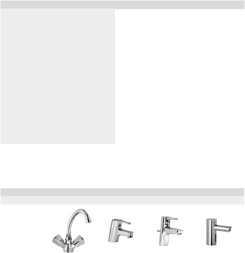
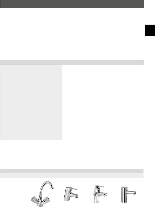
1.2 Empfohlene Niederdruckarmaturen
Armatur-Typ |
SNM |
END |
EWT |
AEN |
Art.-Nr. |
1100-04200 |
1100-04410 |
1100-04420 |
1100-04255 |
|
|
|
|
|
3
|
M 3..7 |
|
Gerätebeschreibung |
DE |
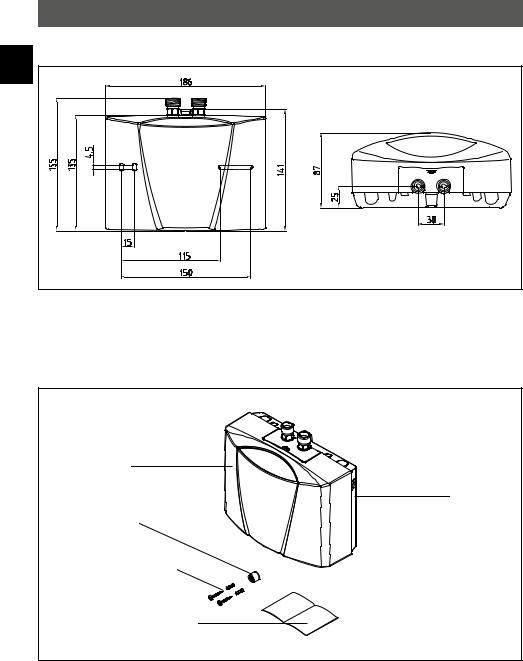
1.3 Abmessungen |
Abb. 1: »Abmessungen« (Maßangaben in mm)
1.4 Lieferumfang
Durchlauferhitzer
Wandhalter
Spezial-Strahlregler
Montageschrauben und Dübel
Gebrauchsund Montageanleitung
Abb. 2: »Lieferumfang«
4
CLAGE
Installation
2. Installation
 Montage, erste Inbetriebnahme und Wartung dieses Gerätes dürfen nur durch einen Fachmann erfolgen, der dabei für die Beachtung der bestehenden Normen und Installationsvorschriften voll verantwortlich ist. Wir übernehmen keine Haftung für Schäden, die durch Nichtbeachtung dieser Anleitung entstehen!
DE
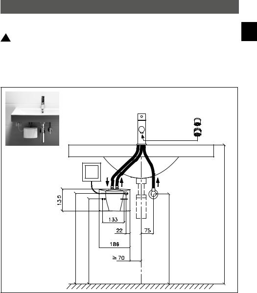
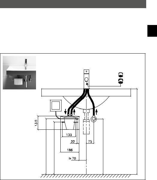
2.1 Installationsbeispiel: Drucklose (offene) Installation
Spezial-Strahlregler einsetzen:
3,5 / 4,4 kW: CSP 3
5,7 / 6,5 kW: CSP 6
Elektroanschluss mit
Netzleitung (ggf. kürzen)
|
|
|
Eckventil Abgang G ⅜" |
Kabeleingang ca. 553 |
Befestigung ca. 520 |
Eckventil ca. 550 |
Waschbeckenoberkante ca. 850 |
Abb. 3: »Drucklose (offene) Installation mit Armatur für drucklose Warmwassergeräte« (Maßangaben in mm)
5
|
|
M 3..7 |
|
|
|
|
|
|
|
Installation |
|
|
|
|
|
|
|
2.2 Montagehinweise |
|
DE |
|||
|
Die Montage erfolgt direkt an die Anschlussleitungen der Sanitärarmatur. Wir garantieren |
||
|
|
eine einwandfreie Funktion des Durchlauferhitzers nur bei Verwendung von CLAGE-Armaturen |
|
|
|
und -Zubehör. Bei der Installation ist Folgendes zu beachten: |
|
|
|
• DIN VDE 0100 und EN 806 sowie die gesetzlichen Vorschriften des jeweiligen Landes und |
|
|
|
die Bestimmungen des örtlichen Elektrizitätsund Wasserversorgungsunternehmens. |
|
|
|
• Technische Daten und Angaben auf dem Typenschild. |
|
|
|
• Für Wartungszwecke muss der Durchlauferhitzer leicht zugänglich sein. Ein separates |
|
|
|
Absperrventil muss installiert sein. |
|
|
|
• Das Gerät darf nur zusammen mit einer Niederdruckarmatur betrieben werden. |
|
|
|
• Es dürfen keine Zubehörteile in der Verpackung zurück gelassen werden. |
|
|
|
• Die Mindestanforderungen an den spezifischen Widerstand des Wassers sind einzuhalten. |
|
|
|
Der spezifische Widerstand des Wassers kann bei Ihrem Wasserversorgungsunternehmen |
|
|
|
erfragt werden. |
|
|
|
• Das Gerät ist nicht für die Warmwasserversorgung einer Dusche geeignet. |
2.3 Wasseranschluss
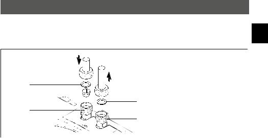
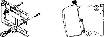
1.Platzieren Sie den Durchlauferhitzer so, dass die Wasseranschlüsse senkrecht nach oben stehen und direkt an die Anschlüsse der Sanitärarmatur angeschlossen werden können.
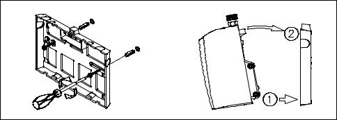
2.Befestigen Sie den Wandhalter mit geeigneten Schrauben und Dübeln an der Wand.
3.Stecken Sie das Gerät von oben auf den Wandhalter und rasten Sie es ein. Das Gerät darf nur betrieben werden, wenn es ordnungsgemäß auf dem Wandhalter eingerastet ist.
Abb. 4: »Montage des Wandhalters«
4. Spülen Sie die Wasserleitungen gründlich durch, bevor Sie diese an das Gerät anschließen.
6
CLAGE
Installation
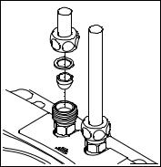
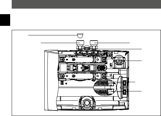
5. Verbinden Sie die Wasseranschlüsse mit den entsprechenden Anschlüssen der Armatur.
Der Wasserzulauf ist auf dem Typenschild, unter der Blende, blau markiert, der Wasser- DE ablauf rot.
a. Dichtung
b. Filtersieb
 . Kaltwasseranschluss (Zulauf) b
d. Warmwasseranschluss (Auslauf)
e. Typenschild-Blende
d
Abb. 5: »Anschluss der Wasserleitungen«
6.Vergewissern Sie sich, dass die Wasserleitungen keine mechanische Kraft auf den Durchlauferhitzer ausüben.
7.Öffnen Sie das Warmwasserventil der Armatur und prüfen Sie alle Verbindungen auf
Dichtheit.
2.4 Elektroanschluss
Vor dem elektrischen Anschluss das Gerät durch mehrfaches Öffnen und Schließen des Warmwasserventiles der Armatur mit Wasser füllen und vollständig entlüften. Sonst ist ein Schaden am Heizelement möglich!
1. Schalten Sie die elektrischen Zuleitungen spannungsfrei.
2.Vergewissern Sie sich, dass der Querschnitt der Zuleitung entsprechend der Angaben in den technischen Daten dieser Anleitung dimensioniert ist.
3.Stellen Sie sicher, dass der Leitungsschutzschalter entsprechend des Querschnittes der Anschlussleitung des Gerätes und des Querschnittes der Zuleitung dimensioniert ist.
4.Durchlauferhitzer mit Schutzkontaktstecker:
a.Überprüfen Sie, dass die Steckdose an den Schutzleiter angeschlossen ist.
b.Stecken Sie die Schutzkontaktstecker in die Steckdose.
Alternativ:
4.Durchlauferhitzer ohne Schutzkontaktstecker:
a. Beachten Sie, dass nach VDE 0700 Installationsseitig eine allpolige Trennung mit einer
7

M 3..7
|
|
|
Installation |
|||
|
|
|
|
|
|
|
|
|
|
Kontaktöffnungsweite von ≥ 3 mm pro Phase vorzusehen ist. |
|||
DE |
||||||
|
|
b. Schließen Sie die Anschlussleitung über eine Geräteanschlussdose nach Schaltplan an. |
||||
|
|
|
||||
|
Alternativ: |
|||||
|
4. Anschluss an eine fest verlegte Leitung: |
|||||
|
|
|
a. Beachten Sie, dass nach VDE 0700 installationsseitig eine allpolige Trennung mit einer |
|||
|
|
|
Kontaktöffnungsweite von ≥ 3 mm pro Phase vorzusehen ist. |
|||
|
|
|
b. Die fest verlegte Leitung muss den Mindestquerschnitt entsprechend der Angabe im |
|||
|
|
|
Kapitel »Technische Daten« erfüllen. Der maximale Querschnitt beträgt 6 mm2. |
|||
|
|
|
c. Öffnen Sie die Haube des Durchlauferhitzers, indem Sie die Typenschild-Blende abneh- |
|||
|
|
|
men, die darunter liegende Gehäuseschraube herausdrehen und die Haube vorsichtig |
|||
|
|
|
abziehen. |
|||
|
|
|
d. Entfernen Sie die vormontierte Anschlussleitung. |
|||
|
|
|
e. Führen Sie die fest verlegten Anschlussleitung durch die Tülle in das Gerät und schließen |
|||
|
|
|
Sie die Adern nach Schaltplan an. Die Tülle muss die Leitung wasserdicht umschließen. |
|||
|
|
|
f. Montieren Sie die Haube wieder auf dem Gerät. |
|||
|
|
|
Der Schutzleiter muss angeschlossen werden! |
|||
|
|
|
||||
|
|
|
||||
|
|
|
|
|
|
|
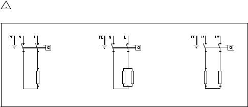
M 3, M 4 (230 V) |
M 6 (230 V) |
M 7 (400 V) |
Abb. 6: »Schaltplan«
8
CLAGE
Installation |
|
|
|
|
|
|
|
2.5 Erstinbetriebnahme |
|
||
DE |
|||
Noch keinen Strom einschalten! |
|||
|
|||
|
|
|
|
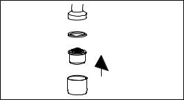
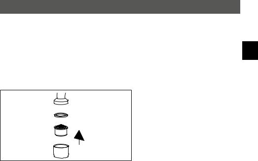
1.Öffnen Sie das Warmwasserventil der Armatur und warten Sie, bis das Wasser blasenfrei heraus strömt, um den Durchlauferhitzer zu entlüften.
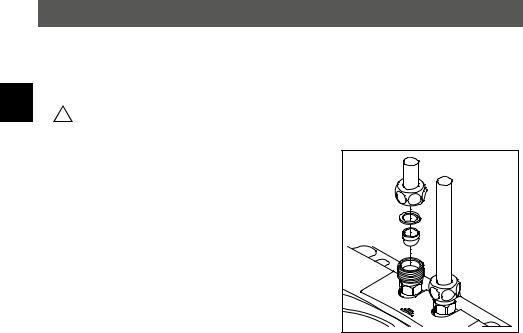
2.Setzen Sie den beigefügten Spezial-Strahlregler in die Hülse (M 22/24) am Auslauf der Armatur, um einen optimalen Wasserstrahl bei sparsamer Durchflussmenge zu erhalten.
Abb. 7: »Spezial-Strahlregler einsetzen«
3.Schalten Sie den Strom ein.
4.Passen Sie gegebenenfalls die Wassermenge an, falls zum Beispiel die Temperatur nicht erreicht wird. Die Vorgehensweise dafür wird im Kapitel »Gebrauch« beschrieben.
5.Erklären Sie dem Benutzer die Funktion und den Gebrauch des Durchlauferhitzers und überreichen Sie ihm diese Anleitung zur Information und Aufbewahrung.
6.Registrieren Sie das Gerät mit der Registrierkarte beim Werkskundendienst oder im Internet unter www.clage.de.
9
|
|
M 3..7 |
|
|
|
|
|
|
|
|
|
|
|
Gebrauch |
|
|
|
|
|
|
|
|
|
|
|
3. Gebrauch |
|
|
|
DE |
|
|
|
||
|
Sobald das Warmwasserventil an der Armatur geöffnet wird, schaltet sich der Durchlauf- |
||||
|
|
erhitzer automatisch ein. Beim Schließen der Armatur schaltet sich das Gerät automatisch |
|||
|
|
wieder aus. |
|
|
|
|
|
3.1 Typenschild-Blende |
|
|
|
|
|
Auf der Unterseite der Blende befinden sich neben der Gerätetypenbezeichnung (1) auch die |
|||
|
|
Geräte-Seriennummer (2) und die Artikelnummer (3). |
|
|
|
|
|
|
|
|
|
|
|
|
1 |
2 |
3 |
|
|
Gerät an Schutzleiter |
AAAA |
|
BBBB |
|
|
anschließen! |
|
|
CCCC |
|
|
Appliance must be earthed! |
|
|
|
|
|
|
|
|
|
Abb. 8: »Typenschild-Blende«
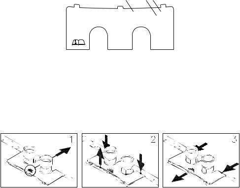
3.1.1 Abnehmen der Blende
Unter dieser Blende befinden sich das Typenschild und die Haubenschraube.
1.Blende an der Riffelung Richtung Wandhalter schieben.
2.An den hinteren Ecken nach unten drücken, bis die Vorderkante hochklappt.
3.Blende nach vorne abziehen.
Abb. 9: »Abnehmen der Blende«
10
CLAGE
Gebrauch |
|
|
|
|
|
|
|
3.2 Einstellen der Wassermenge und Temperatur |
|
||
DE |
|||
Nur durch einen Fachmann auszuführen. |
|||
|
|||
|
|
|
|
Entfernen Sie die Blende, lösen die darunter befindliche Haubenschraube und nehmen die Haube ab.
Die maximal erreichbare Temperatur und die maximale Durchflussmenge sind von den örtlichen Gegebenheiten abhängig.
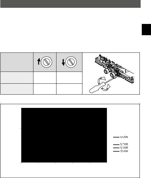
Um bei niedrigen Kaltwassertemperaturen noch eine komfortable Auslauftemperatur bzw. bei hohen Kaltwassertemperaturen eine große Durchflussmenge zu erzielen, kann die Durchflussmenge an der Justierschraube eingestellt werden. Die Drehrichtung ist in der folgenden Abbildung dargestellt:
Drehrichtung |
|
|
Durchflusmenge |
– |
+ |
|
||
Temperatur |
+ |
– |
|
Abb. 10: »Einstellen der Wassermenge und Temperatur«
|
40 |
|
|
|
|
|
|
30 |
|
|
|
|
|
[K] |
25 |
|
|
|
|
|
Temperaturerhöhung |
|
|
|
|
|
|
20 |
|
|
|
|
|
|
10 |
|
|
|
|
|
|
|
|
|
|
|
|
|
|
0 |
|
|
|
|
|
|
0,0 |
1,0 |
2,0 |
3,0 |
4,0 |
5,0 |
|
|
|
|
Warmwasserleistung [l/min] |
|
|
Abb. 11: »Temperaturerhöhung und Warmwasserleistung« |
|
|
||||
11
|
|
M 3..7 |
|
|
|
|
|
|
|
Gebrauch |
|
|
|
|
|
|
|
3.3 Wechsel des Filtersiebes |
|
DE |
|||
|
Der Kaltwasseranschluss des Durchlauferhitzers ist mit einem Filtersieb ausgestattet. Durch |
||
|
|
Verschmutzung dieses Filtersiebes kann die Warmwasserleistung vermindert werden. Eine |
|
|
|
Reinigung, beziehungsweise ein Austausch ist wie folgt vorzunehmen. |
1. Schalten Sie die elektrischen Zuleitungen zum Durchlauferhitzer spannungsfrei.
2.Schließen Sie das Absperrventil in der Zulaufleitung.
3.Lösen Sie die Wasserleitung vom Wasserzulauf. Der Wasserzulauf ist auf dem Typenschild (unter der Blende) blau markiert. Dabei kann Wasser austreten.
4.Hebeln Sie das Filtersieb aus dem Anschlussstück des Durchlauferhitzers heraus und reinigen bzw. ersetzen Sie es.
5.Setzen Sie das saubere Filtersieb wieder in das Anschlussstück ein und verbinden Sie die Wasser leitung mit dem Wasserzulauf des Durchlauferhitzers.
6.Entlüften Sie den Durchlauferhitzer, wie im Kapitel »Entlüften« beschrieben.
7.Schalten Sie die Spannung wieder ein.
Abb. 12: »Wechsel des Filtersiebes« |
3.4 Entlüften
Nach jeder Entleerung (z.B. nach Arbeiten in der Wasserinstallation oder nach Reparaturen am Gerät) muss der Durchlauferhitzer vor der Wiederinbetriebnahme erneut entlüftet werden.
1.Schalten Sie die elektrischen Zuleitungen zum Durchlauferhitzer spannungsfrei.
2.Öffnen Sie das Warmwasserventil der Armatur und warten Sie, bis das Wasser blasenfrei heraus strömt, um den Durchlauferhitzer zu entlüften.
3.Schalten Sie die Spannung wieder ein.
3.5 Reinigung und Pflege
•Kunststoffoberflächen und Sanitärarmaturen nur mit einem feuchten Tuch abwischen. Keine scheuernden, lösungsmitteloder chlorhaltigen Reinigungsmittel verwenden.
•Für eine gute Wasserdarbietung sollten Sie die Entnahmearmaturen (Strahlregler und Handbrausen) regelmäßig abschrauben und reinigen. Lassen Sie alle drei Jahre die elektround wasserseitigen Bauteile durch einen anerkannten Fachhandwerksbetrieb überprüfen, um die einwandfreie Funktion und Betriebssicherheit jederzeit zu gewährleisten.
12

CLAGE
Störungsbehebung
4. Störungsbehebung
DE
4.1 Selbsthilfe bei Problemen
Diese Tabelle hilft dabei, die Ursache einer evtl. Störung zu finden und diese zu beseitigen.
Problem |
Mögliche Ursache |
Abhilfe |
|
|
|
|
|
Es kommt kein Wasser |
Wasserzufuhr versperrt |
Hauptwasserhahn und Eckventil aufdrehen |
|
|
|
|
|
|
Strahlregler fehlt |
Spezial-Strahlregler montieren |
|
|
|
|
|
Es kommt weniger Wasser |
Wasserdruck zu gering |
Fließwasserdruck prüfen |
|
als erwartet |
|
|
|
Verschmutzungen |
Schmutz im Filtersieb, im Eckventil / in der |
||
|
|||
|
Armatur entfernen |
||
|
|
||
|
|
|
|
Das Gerät schaltet sich ein |
Wasserdruck schwankt, |
Verschmutzungen entfernen / Wasserdruck |
|
erhöhen, andere Zapfstellen schließen, |
|||
und aus |
zu geringer Durchfluss |
||
Eckventil weniger drosseln |
|||
|
|
||
|
|
|
|
Obwohl das Gerät hörbar |
Elektroanschluss nicht in Ordnung |
Elektroanschluss prüfen |
|
|
|
||
schaltet, bleibt das Wasser |
Keine Spannung |
Sicherungen in der Hausinstallation überprüfen |
|
kalt |
|
|
|
Heizwendel defekt |
Heizwendel erneuern (Fachmann) |
||
|
|||
|
|
|
|
|
Wasseranschlüsse vertauscht |
Installation überprüfen |
|
|
|
|
|
Das Gerät schaltet nicht |
|
Wassermengeneinstellung prüfen (Fachmann), |
|
Fließwasserdruck zu gering |
Eckventil weniger drosseln, Wasserdruck |
||
hörbar ein und das Wasser |
|||
|
prüfen |
||
bleibt kalt |
|
||
|
|
||
Verschmutzungen |
Verschmutzungen im Zuoder Auslauf besei- |
||
|
|||
|
tigen |
||
|
|
||
|
|
|
|
Die Warmwasser |
Wasserdruck schwankt |
Fließwasserdruck stabilisieren |
|
temperatur schwankt |
Elektrische Spannung schwankt |
Spannung prüfen |
|
|
|
|
|
|
Durchfluss zu hoch oder |
Wassermengeneinstellung anpassen |
|
Die Warmwasser |
Einlauftemperatur zu niedrig |
(Fachmann) |
|
|
|
||
temperatur ist zu niedrig |
Leistungsaufnahme zu niedrig |
Spannungsversorgung prüfen |
|
|
|
|
|
|
M 6: Eine Heizwendel defekt |
Heizwendel erneuern (Fachmann) |
|
|
|
|
Wenn die Netzanschlussleitung des Gerätes beschädigt ist, muss sie durch einen Fachmann ausgetauscht werden, um Gefährdungen zu vermeiden. Die beschädigte Leitung muss durch eine Original-Anschlussleitung ausgetauscht werden (als Ersatzteil erhältlich).
Sollte das Gerät weiterhin nicht einwandfrei funktionieren, wenden Sie sich bitte an den Werkskundendienst.
13
M 3..7
|
Störungsbehebung |
|
DE |
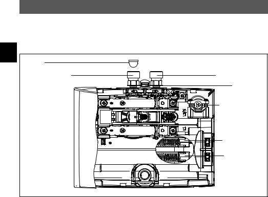
4.2 Ersatzteile |
|
Bei Ersatzteilbestellungen stets Gerätetyp und Seriennummer angeben! |
||
|
Filtersieb |
|
|
Kaltwasseranschluss |
Warmwasseranschluss |
|
|
Wandhalter |
|
|
Netzleitung |
|
|
Zweite |
|
|
Heizwendel |
|
|
(5,7 kW + 6,5 kW) |
|
|
Heizwendel |
|
Abb. 13: »Ersatzteile« |
|
|
4.3 Kundendienstadresse |
|
|
CLAGE GmbH |
|
|
Werkskundendienst |
|
Pirolweg 1 – 5 21337 Lüneburg Deutschland
Fon: |
+49 4131 8901-40 |
Fax: |
+49 4131 8901-41 |
E-Mail: |
service@clage.de |
Falls ein Mangel vorliegt, senden Sie das Gerät bitte mit einem Begleitschreiben und dem Kaufnachweis zur Überprüfung bzw. Reparatur ein.
14
CLAGE
Entsorgung
5. Entsorgung
DE
5.1 Demontage
1. Schalten Sie die elektrischen Zuleitungen zum Durchlauferhitzer spannungsfrei.
2.Schließen Sie das Absperrventil in der Zulaufleitung.
3.Lösen Sie die elektrische Verbindung in der Geräteanschlussdose, beziehungsweise ziehen Sie den Schutzkontaktstecker, sofern das Gerät mit einem Stecker ausgestattet ist.
4.Lösen Sie die Wasserleitungen von den Anschlüssen des Gerätes. Dabei kann Wasser austreten.
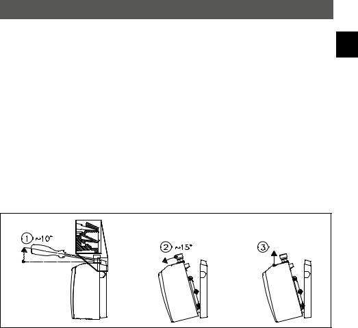
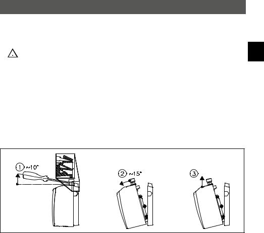
5.Nehmen Sie das Gerät aus dem Wandhalter. Stecken Sie dazu eine breite Schraubendreher spitze bis zum Anschlag in die Verriegelung zwischen den Wasseranschlussstücken und drücken Sie die Verriegelung leicht nach oben. Kippen Sie das Gerät maximal 15° nach vorne und entnehmen Sie es nach oben.
6.Schrauben Sie den Wandhalter von der Wand ab.
Abb. 14: »Abnehmen des Gerätes aus dem Wandhalter«
5.2 Umwelt und Recycling
Ihr Produkt wurde aus hochwertigen, wiederverwendbaren Materialien und Komponenten hergestellt. Beachten Sie bei einer Entsorgung, dass elektrische Geräte am Ende ihrer Lebensdauer vom Hausmüll getrennt entsorgt werden müssen. Bringen Sie dieses Gerät daher zu einer der kommunalen Sammelstellen, die Elektronikschrott entgegennehmen. Diese ordnungsgemäße Entsorgung dient dem Umweltschutz und verhindert mögliche schädliche Auswirkungen auf Mensch und Umwelt, die sich aus einer unsachgemäßen Handhabung der Geräte am Ende ihrer Lebensdauer ergeben könnten. Genauere Informationen zur nächstgelegenen Sammelstelle bzw. Recyclinghof erhalten Sie bei Ihrer Gemeindeverwaltung.
Geschäftskunden: Wenn Sie Geräte entsorgen möchten, treten Sie bitte mit Ihrem Händler oder Lieferanten in Kontakt. Diese halten weitere Informationen für Sie bereit.
15
|
|
|
|
|
|
|
|
|
|
|
|
|
|
3.2 |
Adjusting the water flow and tempera- |
||
|
1.1 |
Technical specifications . . . . . . |
17 |
ture . . . . . . . . . . . . . . . . |
25 |
|||
|
1.2 |
Recommended open-outlet taps . . |
. 17 |
3.3 |
Changing the strainer . . . . . . . |
26 |
||
EN |
||||||||
|
1.3 Dimensions . . . . . . . . . . . |
18 |
3.4 |
Purging . . . . . . . . . . . . . |
26 |
|||
|
1.4 |
Scope of delivery . . . . . . . . . |
18 |
3.5 |
Cleaning and maintenance . . . . |
. 26 |
||
|
|
2. Installation |
|
4. Troubleshooting |
|
|||
|
2.1 |
Typical installation: vented (open) instal- |
4.1 |
Self-help when problems occur . . . |
27 |
|||
|
|
lation . . . . . . . . . . . . . . . |
19 |
4.3 |
Spare parts . . . . . . . . . . . |
. 28 |
||
|
2.2 |
Installation instructions . . . . . . |
20 |
4.2 |
Customer service address . . . . . |
. 28 |
||
|
2.3 |
Water connection . . . . . . . . |
. 20 |
5. Disposal |
|
|||
|
2.4 |
Electrical connection . . . . . . . |
. 21 |
|
||||
|
5.1 |
Disassembly . . . . . . . . . . . |
29 |
|||||
|
2.5 |
Initial start-up . . . . . . . . . . |
23 |
|||||
|
5.2 |
Environment and recycling . . . . . |
29 |
|||||
|
|
|
|
|
||||
|
|
3. Use |
|
6. Product data sheet in accordance with |
||||
|
3.1 |
Rating plate cover . . . . . . . . |
. 24 |
|||||
|
EU regulation 812/2013 814/2013 |
|
||||||
|
|
3.1.1 Removing the cover . . . . . . . |
24 |
(Is attached at the end of this document) |
|
|||
Note: Carefully read the enclosed safety instructions through in full before the appliance is installed, put into service and used and follow them in the further steps and during use!
16
CLAGE
Description of appliance
1. Description of appliance
This instantaneous water heater is intended to provide the economical heating of water suffi- |
|
cient for a single outlet, i.e. handwash basin, and must be connected to a special open-outlet |
EN |
tap to avoid any overpressure. |
When the hot water tap is opened, the instantaneous water heater switches itself on auto matically and heats the water as it passes through the appliance. It is only then that the appliance uses electricity. The temperature increase depends on the flow rate.
1.1 Technical specifications
Type |
|
M 3 |
|
M 4 |
|
M 6 |
|
M 7 |
Energy efficiency class |
|
|
|
|
|
A *) |
|
|
Capacity |
Litre |
|
|
|
0.2 |
|
|
|
Max. operating pressure |
MPa (bar) |
|
|
0 (0); Open outlet only! |
|
|||
Heating system |
|
|
|
Bare wire heating system IES® |
|
|||
Min. water resistance at 15 °C 1) |
Ωcm |
|
|
|
1100 |
|
|
|
Max. water inlet temperature |
°C |
|
|
|
20 |
|
|
|
Rated voltage |
|
|
1~ / N / PE 230 V AC |
|
2~ / PE 400 V AC |
|||
Rated power |
kW |
3.5 |
|
4.4 |
|
5.7 |
|
6.5 |
Rated current |
A |
15.2 |
|
19.1 |
|
24.8 |
|
16.3 |
Required min. cable cross-section |
mm2 |
1.5 |
|
2.5 |
|
4.0 |
|
1.5 |
Hot water output at ∆t = 25 K 2) |
l/min |
2.0 |
|
2.5 |
|
3.3 |
|
3.7 |
Switching on at |
l/min |
1.3 |
|
1.8 |
|
2.2 |
|
2.4 |
Switching off at |
l/min |
1.0 |
|
1.4 |
|
1.7 |
|
2.0 |
Approx. weight when filled with water |
kg |
|
|
|
1.5 |
|
|
|
Protection class |
|
|
|
|
IP 25 |
|
||
Marking / Approvals |
|
|
|
|
see rating plate |
|
||
|
|
|
|
|
|
|
|
|
*) The declaration complies with the EU regulation No 812/2013. The product data sheet is attached at the end of this document.
1)The specific resistance can be asked for at your water distribution company.
2)Temperature increase from e.g. 15 °C to 40 °C.
1.2 Recommended open-outlet taps
Type |
SNM |
END |
EWT |
AEN |
Art. No. |
1100-04200 |
1100-04410 |
1100-04420 |
1100-04255 |
|
|
|
|
|
17

M 3..7
Description of appliance
1.3 Dimensions
EN |
Fig. 1: “Dimensions” (in mm)
1.4 Scope of delivery
Instantaneous water heater
Wall bracket
Special jet regulator
Fixing screws and plugs
Operating and installation instructions
Fig. 2: “Scope of delivery“
18
CLAGE
Installation
2. Installation
 Installation, initial operation and maintenance of this appliance must only be conducted by an authorised professional, who will then be responsible for adherence to EN applicable standards and installation regulations. We assume no liability for any damag-
es caused by failure to observe these instructions!
2.1 Typical installation: vented (open) installation
Insert the special tap aerator:
3,5 / 4,4 kW: CSP 3
5,7 / 6,5 kW: CSP 6
Electrical connection with mains power cable (shorten if necessary)
|
|
Angle valve outlet G ⅜" |
|
Cable inlet approx. 553 |
Fastening approx. 520 |
Angle valve approx. 550 |
Top edge of basin approx. 850 |
Fig. 3: “Vented installation with a special open-outlet tap” (dimensions in mm)
19
|
|
M 3..7 |
||||
|
|
|
|
|
|
|
|
|
|
Installation |
|||
|
|
|
|
|
||
|
|
2.2 Installation instructions |
||||
|
|
The heater is installed directly to the connecting pipes of the tap. We guarantee trouble-free |
||||
|
|
operation of the instantaneous water heater only if CLAGE fittings and accessories are used. |
||||
EN |
||||||
|
Note the following during installation: |
|||||
|
|
• |
Installation must comply with DIN VDE 0100 and EN 806 and with the statutory regulations |
|||
|
||||||
|
|
|
of the country and the provisions of the local electricity and water supply company. |
|||
|
|
• |
Check the technical data and information on the rating plate. |
|||
|
|
• |
Easy access to the instantaneous water heater must be guaranteed at all times for mainte- |
|||
|
|
|
nance purposes. An separate shut-off valve must be installed. |
|||
|
|
• |
Only use the appliance with an open-outlet tap. |
|||
|
|
• |
Ensure that all accessories are removed from the packaging. |
|||
|
|
• |
The minimum requirements for the required water resistance must be complied with. The |
|||
|
|
|
required water resistance of the can be obtained from your water supply company. |
|||
|
|
• |
This appliance is not suitable for warm water supply to showers. |
|||
|
|
2.3 Water connection |
||||
|
1. |
Position the instantaneous water heater with the water connectors vertically upwards for |
||||
|
|
|
direct connection to the tap. |
|||
|
2. |
Secure the wall bracket to the wall with suitable screws and dowels. |
||||
|
3. |
Place the appliance onto the wall bracket and snap it into position. Only use the appliance |
||||
|
|
|
if it is fitted correctly to the wall bracket. |
|||
|
|
|
|
|
|
|
|
|
|
|
|
|
|
|
|
|
|
|
|
|
|
|
|
|
|
|
|
|
|
|
|
|
|
|
|
|
|
|
|
|
|
|
|
|
|
|
|
|
|
|
|
|
|
|
|
|
|
|
|
|
|
|
Fig. 4: “Installing the wall bracket”
4.Rinse the water pipes thoroughly before connecting them to the appliance.
5.Connect the water connectors with the relevant tap connectors. The water inlet is indicated in blue on the rating plate (under the cover) and the water outlet in red.
20
CLAGE
Installation
|
|
a. Seal |
a |
|
b. Filter |
b |
|
c. Cold water connection (inlet) |
|
d. Hot water connection (outlet) |
|
|
a |
|
|
e. Rating plate cover |
|
c |
|
|
|
|
|
e |
d |
|
|
|
EN
Fig. 5: “Connecting the water pipes”
6.Make sure that the water pipes do not apply any kind of mechanical pressure on the instantaneous water heater.
7.Open the hot water valve of the tap and check all connections for leaks.
2.4 Electrical connection
Fill the appliance with water by repeatedly opening and closing the hot water tap before connecting to electrical power and purge completely. The heating element may be damaged if this is not done!
1. Check that the power supply is switched off.
2.Make sure that the cross-section of the supply line corresponds to the details in the technical specifications of these instructions.
3.Ensure that the dimensions of the circuit breaker do correspond with the cross-section of the connecting cable of the appliance and to the cross-section of the supply line.
4.Instantaneous water heater with plug:
a.Check that the socket is connected to the protective earth conductor.
b.Plug the plug into the socket.
Alternatively:
4.Instantaneous water heater without plug:
a.Note that according to VDE 0700, an all-pole disconnecting device with a contact opening width of ≥ 3 mm per phase must be provided at the installation end.
b.Connect the connecting pipe via a junction box to the mains, as shown in the circuit diagram.
21
M 3..7
|
|
|
Installation |
||
|
|
|
|
|
|
|
|
Alternatively: |
|||
|
|
4. Connection to a permanently installed cable: |
|||
|
|
|
a. Note that according to VDE 0700, an all-pole disconnecting device with a contact open- |
||
EN |
|
|
|||
|
|
ing width of ≥ 3 mm per phase should be provided at the installation end. |
|||
|
|
|
|||
|
|
|
b. The cross-section of the cable must meet the requirements of the minimal cross-section, |
||
|
|
|
as mentioned in chapter “Technical specifications“. The maximum applicable cross-sec- |
||
|
|
|
tion is 6 mm2. |
||
|
|
|
c. Open the cover. |
||
|
|
|
d. Dismount the pre-installed connection cable. |
||
|
|
|
e. Route the permanently installed cable through the grommet and connect it as shown in |
||
|
|
|
the circuit diagram. Make sure that the grommet fits tightly around the cable to ensure |
||
|
|
|
optimal protection against water. |
||
|
|
|
f. Refit the cover on the appliance. |
||
|
|
|
The earth conductor must be connected! |
||
|
|
|
|||
|
|
|
|||
|
|
|
|
|
|
M 3, M 4 (230 V) |
M 6 (230 V) |
M 7 (400 V) |
Fig. 6: “Circuit diagram”
22
CLAGE
Installation |
|
|
2.5 Initial start-up |
|
|
Do not switch on the electric power at this time! |
|
|
1. To purge the instantaneous water heater, open the hot water tap and wait until the water |
EN |
|
emerges free of air bubbles. |
||
|
2.In order to obtain an optimum water jet at low flow rates, screw the enclosed special tap aerator into the tap outlet (M 22/24).
Fig. 7: “Fitting the special tap aerator“
3.Switch on the electric power.
4.Adapt the water flow if necessary, if for example the temperature is not reached. The procedure is described in the chapter “Use”.
5.Explain the functions and use of the instantaneous water heater to the user and hand over these operating instructions to the user for information and future reference.
6.Register the appliance with the customer service department using the registration card or online at www.clage.com.
23

M 3..7
Use
3. Use
As soon as the hot water tap is opened, the instantaneous water heater switches on automati- EN cally. Close the tap and the appliance switches off automatically again.
3.1 Rating plate cover
On the inner part of the cover you can find the name of the application type (1), as well as the serial number (2) and the article number (3).
1 |
2 |
3 |
Gerät an Schutzleiter |
AAAA |
BBBB |
anschließen! |
|
CCCC |
Appliance must be earthed! |
|
|
Fig. 8: “Rating plate cover”
3.1.1 Removing the cover
Under this cover, the rating plate and the hood screw are located.
1.Push the cover at the corrugation towards the wall bracket.
2.At the rear corners press the cover down until the front edge lifts.
3.Remove the cover by pulling forward.
Fig. 9: “Removing the cover”
24
CLAGE
Use
3.2 Adjusting the water flow and temperature May only be carried out by a specialist.
Remove the cover, undo the hood screw underneath and remove the hood. |
EN |
|
The maximum temperature and flow depend on the conditions at the installation site.
In case of quite low or high cold water temperatures, you may reduce or increase the flow with the adjustment screw to achieve a comfortable outlet temperature. See figure below for direction of rotation:
Direction of rotation |
|
|
Flow |
– |
+ |
|
||
Temperature |
+ |
– |
|
Fig. 10: “Adjusting the water flow and temperature”
|
40 |
|
|
|
|
|
|
30 |
|
|
|
|
|
[K] |
25 |
|
|
|
|
|
increase |
|
|
|
|
|
|
20 |
|
|
|
|
|
|
|
|
|
|
|
|
|
Temperature |
10 |
|
|
|
|
|
|
|
|
|
|
|
|
|
0 |
|
|
|
|
|
|
0,0 |
1,0 |
2,0 |
3,0 |
4,0 |
5,0 |
|
|
|
|
Hot water output [l/min] |
|
|
Fig. 11: “Temperature increase and hot water output”
25
M 3..7
Use
3.3 Changing the strainer
The cold water connection of the instantaneous water heater is equipped with a strainer. Dirt EN deposited in this strainer can reduce the hot water output. Clean or replace as follows.
1.  Switch off the power supply to the instantaneous water heater.
2.Close the shut-off valve in the inlet pipe.
3.Disconnect the water pipe from the water inlet. The water inlet is indicated in blue on the rating plate (under the cover). This can cause water leakage.
4.Lever the strainer out of the connection piece of the instantaneous water heater and clean or replace it.
5.Insert the clean strainer into the connection piece and connect the water pipe to the water inlet of the instantaneous water heater.
6.Purge the instantaneous water heater as described in the chapter “Purging”.
Fig. 12: “Changing the strainer” |
7.Switch the power supply back on again.
3.4Purging
Each time it is emptied (for example after work on the plumbing system or following repair work on the appliance), the instantaneous water heater must be purged before it is used again.
1.Switch off the power supply to the instantaneous water heater.
2.To purge the instantaneous water heater, open the hot water tap and wait until the water emerges free of air bubbles.
3.Switch the power supply back on again.
3.5 Cleaning and maintenance
•Plastic surfaces and fittings should only be wiped with a damp cloth. Do not use abrasive or chlorine-based cleaning agents or solvents.
•For a good water supply, the outlet fittings (special tap aerators and shower heads) should be unscrewed and cleaned at regular intervals. Every three years, the electrical and plumbing components should be inspected by an authorised professional in order to ensure proper functioning and operational safety at all times.
26

CLAGE
Troubleshooting |
|
|
|
|
|
|
|
|
|
4. Troubleshooting |
|
|
|
|
4.1 Self-help when problems occur |
|
|
|
|
|
|
EN |
||
The following table will help you to determine and rectify the reasons for possible problems. |
||||
|
|
|
|
|
Problem |
Possible cause |
Remedy |
|
|
|
|
|
|
|
No water flows |
Water supply is turned off |
Open the main water valve and angle valve |
|
|
|
|
|
|
|
|
Special tap aerator is not fitted |
Fit the special tap aerator |
|
|
|
|
|
|
|
Water flows more slowly |
Water pressure too low |
Check the water flow pressure |
|
|
than expected |
|
|
|
|
Dirt in the pipes |
Remove any dirt from the filter, angle valve |
|
|
|
|
|
|
||
|
and tap |
|
|
|
|
|
|
|
|
|
|
|
|
|
The appliance switches |
Water pressure fluctuates, |
Remove any dirt / increase the water flow |
|
|
pressure, close other taps, open angle valve |
|
|
||
itself on and off |
flow rate is too low |
|
|
|
further |
|
|
||
|
|
|
|
|
|
|
|
|
|
Water remains cold even |
Electric supply incorrect |
Check the electric supply |
|
|
|
|
|
|
|
No voltage |
Check fuses in the electrical installation |
|
|
|
though the appliance |
|
|
||
|
|
|
|
|
|
Replace heating element (by authorised tech- |
|
|
|
switches on |
Faulty heating element |
|
|
|
|
nician) |
|
|
|
|
|
|
|
|
|
|
|
|
|
|
Water connections mixed up |
Check installation |
|
|
|
|
|
|
|
Appliance does not switch |
|
Check water flow setting (by authorised tech- |
|
|
on and the water remains |
Water flow pressure too low |
nician), open angle valve further, check water |
|
|
cold |
|
pressure |
|
|
|
|
|
|
|
|
Dirt in the pipes |
Remove dirt from the inlet and outlet pipes |
|
|
|
|
|
|
|
Hot water temperature |
Water pressure fluctuates |
Stabilise the water flow pressure |
|
|
varies |
Supply voltage varies |
Check the supply voltage |
|
|
|
|
|
|
|
|
Flow rate is too high or inlet tem- |
Adjust the water flow (by authorised techni- |
|
|
Hot water temperature is |
perature is too low |
cian) |
|
|
|
|
|
|
|
Power supply is too low |
Check the power supply |
|
|
|
too low |
|
|
||
|
|
|
|
|
M 6: A faulty heating element |
Replace heating element (by authorised tech- |
|
|
|
|
|
|
||
|
nician) |
|
|
|
|
|
|
|
|
|
|
|
|
|
If the connection cable is damaged, it must be replaced with an original spare cable from the manufacturer by an authorised technician in order to avoid any hazards.
If you cannot rectify the fault with the aid of the troubleshooting table, please contact the customer service.
27
|
M 3..7 |
|
|
Troubleshooting |
|
|
4.3 Spare parts |
|
|
When ordering spare parts, please always specify the appliance model and serial |
|
EN |
number. |
|
|
Strainer |
|
|
Cold water connection |
Hot water connection |
|
|
Wall bracket |
|
|
Power supply cable |
|
|
Second |
|
|
heating element |
|
|
(5.7 kW + 6.5 kW) |
|
|
Heating element |
|
Fig. 13: “Spare parts” |
|
4.2 Customer service address CLAGE GmbH
After-Sales Service
Pirolweg 1 – 5 21337 Lüneburg Germany
Phone: +49 4131 8901-40 Fax: +49 4131 8901-41 Email: service@clage.de
If there is a fault with the appliance, please send in the heater with details of the problem and a copy of the sales invoice for examination or repair.
28
CLAGE
Disposal
5. Disposal
5.1 Disassembly
1. |
|
Switch off the power supply to the instantaneous water heater. |
EN |
|
|||
|
|
2.Close the shut-off valve in the inlet pipe.
3.Disconnect the electrical connection in the appliance junction box or disconnect the protective earth plug if the appliance is fitted with a plug.
4.Disconnect the water pipes from the connectors of the appliance. This can cause water leakage.
5.Remove the appliance from the wall bracket. To do so, insert the tip of a wide screwdriver as far as it will go into the latch between the water connection pieces and push the latch slightly upwards. Tilt the appliance forward by max. 15° and remove it by lifting it upwards.
6.Unscrew the wall bracket from the wall.
Fig. 14: “Removing the appliance from the wall bracket”
5.2 Environment and recycling
Your product was manufactured from high-quality, reusable materials and components. Please respect in case of discarding that electrical devices should be disposed of separately from household waste at the end of their service life. Therefore, please take this device to a municipal collection point that accepts electronic scrap. Disposing it correctly will support environmental protection and will prevent any potential negative effects on human beings and the environment that could arise from inappropriate handling of these devices at the end of their service life. Please contact your local authority for further details of your nearest designated collection point or recycling site.
Business customers: If you wish to discard equipment, please contact your dealer or supplier for further information.
29

FR
Loading...