

Page 1

Page 2

alphabetic index
1
Page 3

9 Chapter I: Driving 45 Clutch control, auxiliary
65 Chapter II: Main- 13 Coolant level
tenance 38 Dashboard
99 Chapter III: Comfort 42, 52 Dashboard stowage
104-107 Air conditioning 107 Defrosting-demisting
69 Anti-freeze 44, 54 Direction indicators
16 Anti-theft 10 Doors (opening and
42, 52, 109 Ashtrays closing)
69 Battery 91 Electrical terminal, for
10 Bonnet (opening and accessories
closing) 10 Engine dipstick
13 Brake and hydraulic 72 Filters, air and hydraulic
system fluid, level 41, 51 Fuel gauge
33 Brake, hand 92 Fuses
33 Brake operation, check 25 -29 Gear changing
29-34, 75 Brakes 43 ,53 Glove compartment
78 Bulb replacement 7 Guarantee overhaul
103 Carpets, attachment 84 Headlight adjustment
10 Checks before setting off 44, 54 Headlight
46, 56 Clock, electric "flashing"
2
Page 4

104 Heating 100 Seats
59 Height adjustment 96 Scratched paintwork,
(ground clearance) touching up
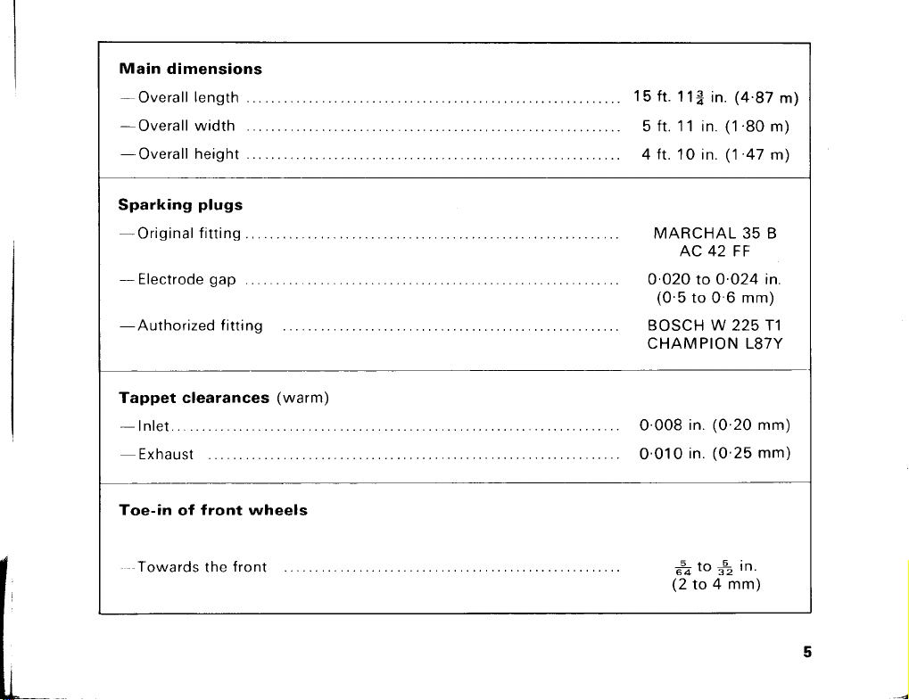
14 Hydraulic circuit, draining 5, 91 Sparking plugs
69 Injection 19 Starting engine
109 Lighting, boot 25, 45 Starting handle
46, 56 Lighting, interior 36 Stopping and starting off
66 Lubrication on a gradient
34 Stopping distances
94 Maintenance of fittings, 109 Sun vizors
mirrors and external 4 Technical data and
embellishments adjustments
36 Parking manoeuvres 93 Towing
70, 71 Radiator 76 Tyres
42, 52 Rear view mirror 107 -108 Ventilation
41, 52 Revolution counter, 44 Warning devices
electronic 44, 48 Warning light dial
6 Running in 61 Wheels, changing
103 Safety belts 43, 75 Windscreen washers
3
Page 5
Page 6
Page 7

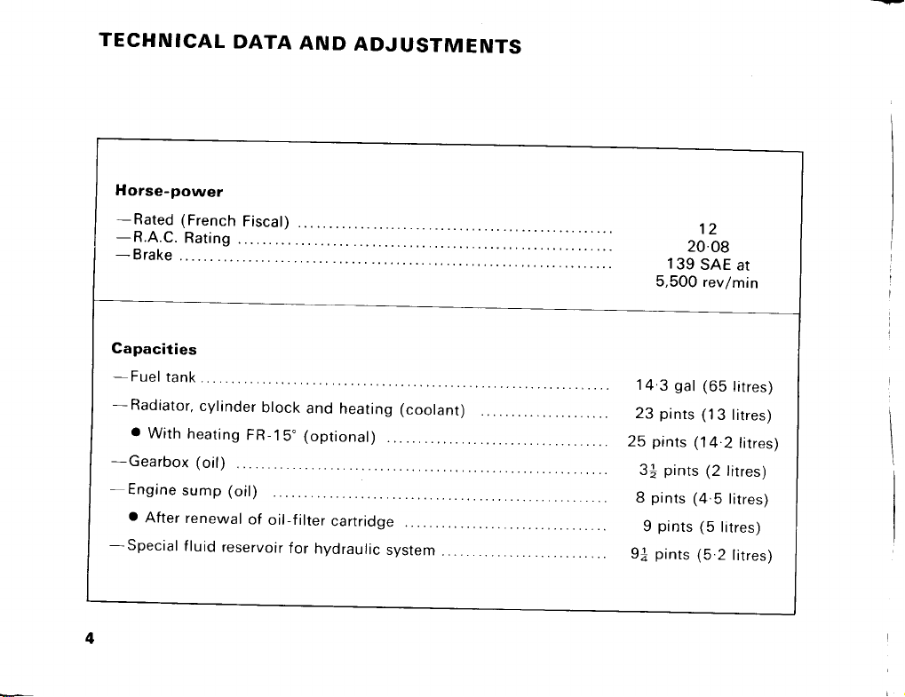
IMPORTANT POINTS
Only the "Premium" (4-star, 97-99 octane) type of fuels can be used with the
DS engine.
If another make of sparking plug is to be used consult a CITROEN Agent
beforehand to ensure that a type of plug is fitted which suits the engine and its
operation.
This car is equipped with an alternator supplying an electrical system at 1 2 Volt
and a 200/40 Ah IEC battery.
• Never disconnect the battery or the alternator with the engine running.
• Never connect a battery charger to the battery terminals unless the two leads
linking the battery and the car circuit are disconnected.
Warning:
• Ensure that when reconnecting the battery the correct polarity is obtained: a
mistake would quickly ruin the electronic injection control.
• Never connect battery chargers or electric supplies with rated voltages in
excess of 1 2 V.
Running in
The following speeds must not be exceeded during the first 600 miles (1,000
kilometres):
15 mph (25 km/h) in bottom gear 44 mph (70 km/h) in third gear
28 mph (45 km/h) in second gear 62 mph (100 km/h) in top gear
Between 600 and 1,200 miles (1,000 and 2,000 kilometres) the car should
still not be loaded to the maximum.
6
Page 8

Over 1,200 miles (2,000 kilometres) there is no restriction so that you can
drive at: 28 mph (45 km/h) in bottom gear
53 mph (85 km/h) in second gear 80 mph (130 km/h) in third gear
These maximum speeds are marked on the speedometer with yellow-orange
lines.
To obtain the most economic running the following points should be borne in
mind:
1 Always select the highest possible gear, both in town and on the open road.
2 Avoid systematically pushing the engine to its maximum power ("foot to the
floorboard").
3 Release the accelerator pedal completely by taking the foot off whenever
you want to slow down.
At the 600 mile (1,000 km) service: Have the engine oil and the oil-filter
cartridge renewed; the gearbox oil too should be renewed.
GUARANTEE OVERHAUL
At the time of delivery your supplier will also hand over a "Maintenance
Log-book" which includes the "Guarantee Card".
When these documents are presented to any Citroen Agent he will carry out an
overhaul after your car has completed 600 miles (1,000 kilometres). The
work involved is free of charge, payment only being required for the new oil in
the engine and gearbox and for the filter cartridge.
On completion of the work the Agent (or Branch) retains the "Overhaul
Certificate" and returns the "Maintenance Log-book" in which he has
signed the "Guarantee Card".
7
Page 9

Keep this Card in a safe place since it will be called for if you make a claim under
Clause VII and VIII of our General Sales Conditions printed on the back of the
Guarantee Card.
The oil level should be checked several times before the first 600 mile (1,000 km)
overhaul becomes due:
• If the level is near the "low" mark top up with new TOTAL Altigrade GT
"Motorway Special" 20 W 40.
• Topping up must be done on level ground after the engine has been stopped for at
least five minutes.
• Check the level two or three times, wiping the dipstick clean before every
insertion.
Subsequently the instructions contained in the "Maintenance Log-book"
should be strictly complied with: conscientious servicing will help to keep your
car in good running order.
8
Page 10

1 DRIVING
9
Page 11

Driving
OPENING AND LOCKING THE DOORS (fig. 1)
To open a door grasp the handle and press the catch A with the thumb, the
catch being moved from front to rear.
To lock a rear door once it is closed press the catch A with the thumb, this time
moving the catch forward.
To unlock depress the button B.
The front doors can be locked with a key. A retractable device holds the doors
open, thus making entering or leaving the car easier.
OPENING THE BONNET (figs 2 4)
First pull the two release rings A on the left and right underneath the dashboard:
this action allows the bonnet to rise slightly.
Facing the car release the safety catch by sliding the hand between the edge of
the bonnet and the front bumper to the right of the number plate in order to lift
the lever B.
To keep the bonnet open engage the end of the stay C in its support D on the
left of the radiator.
CHECKS BEFORE SETTING OFF (figs. 5-6)
Engine oil
The dipstick can be found on the left of the engine beside the inlet manifold.
10
Page 12

Page 13

Page 14

Driving
The oil level must reach the upper "High" notch of the dipstick
without exceeding it.
The distance between the "High" and "Low" notches of the dipstick represents
about 1 3/4 pints (1 litre).
The oil-filler opening is at C.
The holder for the spare oil can is in the centre of the spare wheel (fig. 3).
Coolant
The level should be within 3/4 to 11/4 inches (2 to 3 cm) from the lower rim of
the radiator tank filler opening.
If the level requires topping up on the road be careful when removing the radiator
cap since the system is under slight pressure when the engine is warm.
• First turn the cap a quarter of a turn into its safety notch and wait for the
pressure to fall before taking off the cap altogether.
• If the engine is hot it is advisable to wait until it has cooled down a little.
FLUID FOR THE HYDRAULIC SYSTEM (fig. 7-10)
This fluid (green in colour) is a MINERAL one (similar to the engine oil).
The level of this fluid in the reservoir beside the radiator should lie between the
"High" and "Low" marks on the transparent indicator at A.
This level must be read with the car at its maximum height.
13
Page 15

Page 16

Driving
To achieve this start the engine, accelerating slightly to save time. Set the lever A
(fig. 23 and 24) to position 5 and wait until the car has settled at its maximum
height.
Check now that the level is steady between the "High" and "Low" marks of the
transparent indicator at A.
To top up only use the green fluid "LHM" distributed by the firm "TOTAL".
No other fluid may be used, especially those of a vegetable or synthetic
origin such as CH 12-04, LHS2 or brake fluids: these quickly and completely
ruin the car's hydraulic system.
IN AN EMERGENCY you can use:
• either engine oil TYPE SAE 10 or SAE 20,
• or oil for a hydraulic transmission FLUID A, TYPE A,
ensuring that the reservoir is drained at the earliest opportunity and the
prescribed fluid is substituted.
To drain the reservoir lower the car to its minimum height by moving the lever A
(fig. 23) to position 6, then open the bleed screw on the Pressure Regulator.
Unclip the tube B at C (fig. 9) from the lower clips and bend the tube
downwards.
Remove the blanking plug D (fig. 10) and allow the fluid to drain from the
reservoir.
Reset the lever to NORMAL (position 2) after refilling.
15
Page 17

Driving
ANTI-THEFT LOCK WITH BUILT-IN IGNITION-SWITCH IN THE DS FA (fig. 11)
The anti-theft housing located in the dashboard at 25 (fig. 19) combines the
ignition-switch and the steering column lock.
Starting the engine
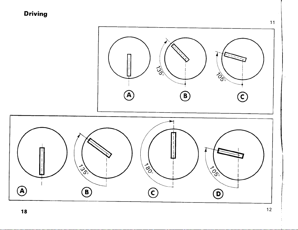
Insert the key into the housing lock (diagram A fig. 11) and turn the key clockwise
until a click is felt: the steering is now unlocked. If difficulty is experienced when
turning the key clockwise turn the steering wheel slightly in both directions while
turning the key. Continue turning the key in the same direction as far as the first
stop (diagram B) at which point ignition contact is made.
Push the gear-selector lever/starter control 7 (fig. 1 3) to the left as far as the stop
for starting the engine.
Switching the engine off and anti-theft device
To switch off turn the key anti-clockwise as far as the first stop, then withdraw
the key slightly and continue turning until the second stop.
The key can now be withdrawn.
Parking
If for some reason the engine is to be stopped without locking the steering, gently
turn the key about 300 anti-clockwise and at the same time pull it towards you
(diagram C).
The key can then be withdrawn without locking the steering column.
16
Page 18

Driving
ANTI-THEFT LOCK WITH BUILT-IN IGNITION-SWITCH AND STARTER
CONTROL IN THE DS FB (fig. 12).
The anti-theft housing located in the dashboard at 25 (fig. 21) provides the
following:
− ignition-switch,
− starting the engine and
− steering column lock.
Starting the engine
Insert the key into the housing lock (diagram A, fig. 1 2) and turn it clockwise until
a click is felt: the steering is now unlocked.
Note: If difficulty is experienced when turning the key clockwise to start slightly
turn the steering wheel in both directions while turning the key. Continue turning
the key in the same direction as far as the first stop (diagram B) at which ignition
contact is made.
Turn further until the second stop, the starter is energized and the engine is
started (diagram C).
Note: A safety device prevents the starter being used with the engine running.
Should the engine stop, therefore, the ignition has to be switched off and on
again before the starter can be used again.
17
Page 19
Page 20

Driving
Switching the engine off and anti-theft device
To switch off turn the key anti-clockwise as far as the first stop, then
withdraw the key slightly and continue turning until the second stop.
Pull out the key.
Parking
If for some reason the engine is to be stopped without locking the steering,
gently turn the key about 300 anti-clockwise and at the same time pull it towards
you (diagram D, fig. 12). The key can then be withdrawn without locking the
steering column.
STARTING THE DS FA (fig. 13)
Check that the gear-selector/starter lever 7 is in neutral (PM).
Switch on (diagram B, fig. 11) whereupon the warning light K of the dial 3
(fig. 20) lights up, also the warning lights C for the oil pressure and H for battery
charging.
When the engine is cold : Depress the accelerator pedal slightly. Push the
gear-selector/starter lever 7 fully towards the left until the engine starts. Do not
persist for more than 1 0 seconds at a time.
If the engine fails to start at the first attempt wait 3 to 4 seconds before
trying again.
19
Page 21

Driving
When started from cold the engine is set to run at a fairly high speed.
If you want to drive off immediately apply the main footbrake before engaging a
gear.
Note: Cars equipped with the optional "FR-15" heating system have a radiator
blind: instructions for its use are contained in a complementary pamphlet supplied
with this manual.
When the engine is warm
Slightly depress the accelerator pedal.
Push the gear-selector/starter lever to the left until the engine starts (do not
persist for longer than 5 seconds at a time).
• If the engine fails to start at the first attempt wait 3 to 4 seconds before trying
again.
• As soon as the engine has started the accelerator pedal can be released to
the slow-running position.
Important points
The starting handle can be used to free the engine or to rotate the engine to start
when the battery is flat. (See page 45, No.27).
After a lengthy period in the garage or after a fault in the fuel system this system
can be primed by switching on the ignition 2 or 3 times before using the starter.
Proceed then as described above.
20
Page 22

Driving
Before setting off allow the engine to run for a while so that the car can
assume its running position.
STARTING THE DS FB (fig. 14)
Ensure that the gear lever 7 is in neutral (PM).
Switch on (diagram B, fig. 1 2): the warning light K in the dial 3 (fig. 20) lights up,
also the warning lights C for the oil pressure and H for battery charging.
When the engine is cold
Operate the starter motor, using key 25 (fig. 21)-diagram C-without touching the
accelerator pedal. The lights K, C and H go out as soon as the engine starts (fig.
20).
• If the engine fails to start at the first attempt wait 3 to 4 seconds before trying
again.
• Never race a cold engine.
Note: Cars equipped with the optional "FR-15" heating system have a radiator
blind: instructions for its use are contained in a complementary pamphlet supplied
with this manual.
When the engine is warm
Depress the accelerator pedal, then operate the starter control.
21
Page 23

Page 24

Page 25
Page 26

Driving
If the engine fails to start at the first attempt keep the pedal depressed, wait
3 to 4 seconds and try again.
• As soon as the engine has started the accelerator pedal can be released to
the slow-running position.
Important points
The engine can also be freed or started with the handle which is stowed under
the spare wheel; it is held in position in the extension. To insert the handle
remove the blanking plug from underneath the bumper and slide the handle in to
engage the hexagon.
After a lengthy period in the garage or after a fault in the fuel system, this system
can be primed by switching the ignition on 2 or 3 times before using the starter.
Proceed then as described above.
Before setting off allow the engine to run for a while so that the car can assume
its running position.
CHANGING GEAR ON THE DS FA (fig 13 and 15)
Since the clutch is automatic the car does not have a clutch pedal.
To change gear merely set the stem of the gear selector/starter lever 7 (fig. 1 3)
opposite one of the marks:
1 − AR
2−3−4 − at the base of the lever.
25
Page 27

Driving
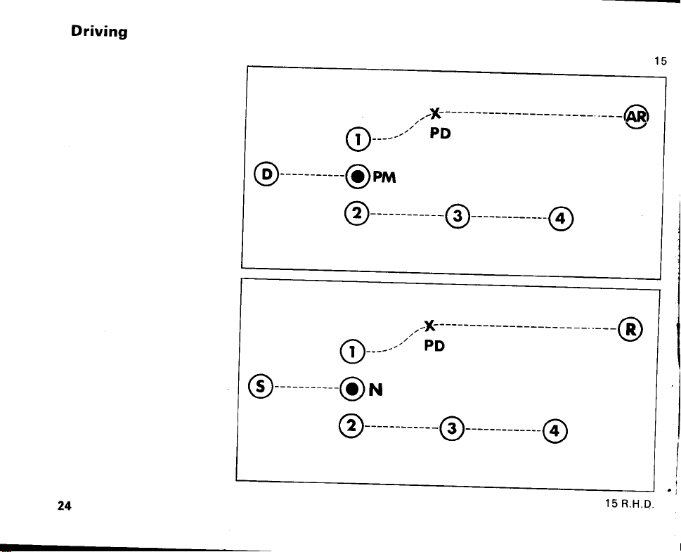
The selector lever can move in several parallel planes in accordance with the
diagram (fig. 15):
The positions corresponding to bottom and reverse gear are in the planes
away from the driver.
The positions corresponding to 2nd, 3rd and top gear are in the planes
closest to the driver.
To change from bottom to reverse gear the selector lever has to be pushed
towards the windscreen in order to overcome the "gate" PD (fig. 1 5) before the
lever can be moved to the extreme right.
In addition to the marks on the dashboard "notching rollers" with a light but
perceptible action enable the driver to feel the various gear positions.
To select a higher gear - release all pressure on the accelerator pedal.
To select a lower gear - release the pressure on the accelerator pedal very
slightly, in fact at the higher engine speeds a lower gear is best selected without
raising the foot.
Gradual pressure on the accelerator pedal gives the car a gentle acceleration; a
sudden movement of the foot down to the floorboards results in vigorous
acceleration. When stationary a gear should not be selected as long as the
engine is running at its "cold start" fast idle, since at this engine speed there
would be violent clutch action. Remember to depress the "mushroom-shaped"
pedal of the main brake beforehand. Under very exceptional circumstances it is
possible for the car not to start off after changing into bottom gear. In such a case
return to neutral (PM in fig. 1 5) between bottom and 2nd gears and set off by
changing into bottom or second.
26
Page 28

Page 29

Driving
CHANGING GEAR ON THE DS FB (fig. 14 and 16)
Push the clutch pedal fully home and gently select the gear with the lever 7 (fig.
4) to the right of the steering wheel.
The gear lever can move in three parallel planes.
In the plane closest to the driver it controls bottom and second gear (pull lever
towards you).
In the intermediate plane it controls third and top gear.
In the plane farthest from the driver it selects reverse gear.
BRAKES ON THE DS FA (fig. 17)
The DS model is equipped with two braking systems actuated by pedals.
I The main brake
The main brake is actuated by the mushroom shaped pedal A near the
driver's right foot. Its movement is very short (a few fractions of an inch). The
effectiveness of the brake is proportional to the pressure exerted by the foot
on the pedal.
The braking system is designed so that it requires only a slight effort on the
part of the driver, even if a sudden stop becomes necessary.
Before setting off in a DS for the first time it is advisable to try the brake in
order to assess its feel, i.e. its sensitivity and efficiency.
29
Page 30

Driving
2 The emergency brake
This brake is actuated by the pedal B used by the left foot.
Contrary to the action of the other controls in the car, which are all
extremely gentle, the emergency brake requires very energetic pressure
by the foot.
The emergency brake is also used to immobilize the car as follows:
• Raise the button C (fig. 17) to the upper position and push the pedal B hard
down: the car is now perfectly immobilized and remains so as long as the
button C is not touched.
• The safety lock D when pushed to the left secures button C in the upper
position (brake applied).
• When stopping on a gradient it is essential that the pedal B be pushed
down very energetically.
• To release the emergency brake unlock it by pushing the button D towards
the right, pull the button C and lower it into the notch E. The button C must
always be at this position when the car is in motion.
When the movement of the emergency brake becomes excessive have it
adjusted by a CITROEN Agent.
BRAKES ON THE DS FB (fig. 18)
The DS Series FB is equipped with two braking systems:
1 The main brake
The main brake is actuated by a mushroom-shaped pedal near the driver’s right
foot. Its movement is very short (a few fractions of an inch).
30
Page 31

Page 32

Driving
The effectiveness of the brake is proportional to the pressure exerted by the
foot on the pedal. The braking system is designed so that it only requires a
slight effort on the part of the driver, even if a sudden stop becomes
necessary. Before setting off for the first time it is advisable to try the footbrake
in order to assess its feel, i.e. its sensitivity and efficiency.
2 The handbrake
The handbrake lever A is located within reach of the driver.
To apply it pull the handle, the ratchet holding it in the selected position. To
release the handbrake pull the handle to free the ratchet, push the free end of
the catch B to clear the ratchet and move the lever fully forward.
A safety device can lock the ratchet catch in position: it is applied by giving the
knurled nut C a quarter of a turn.
When stopping on a gradient the handle A must be pulled with a
considerable effort.
When the movement of the handbrake lever becomes excessive have the
brake adjusted by a CITROEN Agent.
BRAKE MONITOR
If the pressure of the brake hydraulic system controlling the main footbrake
becomes insufficient the red warning light B in the dial 3 (figs. 20 and 22)
lights up, also the STOP warning light K.
33
Page 33

Driving
As soon as the wear of the front brake pads becomes appreciable so that
replacement is necessary the yellow warning light G in the dial 3 comes on.
Should these warnings appear while on the road it is vital that you should have
the braking system inspected by the nearest CITROEN Agent, driving with extra
care to reach him.
When switching on for starting the red warning light B comes on: this is quite
normal. Wait for it to go out before setting off.
You are reminded that the efficient operation of the engine or of the brakes
precludes fitting anything:
either in the air duct to the engine
or in front of the cooling ducts for the brakes.
STOPPING DISTANCE
The soft suspension of the DS and its general comfort coupled with the monotony
of motorway driving or a long journey tend to make the driver unaware of speed.
Added to this the top speed of the DS has been raised year after year.
Bear in mind that the rate of deceleration produced by the most efficient brakes is
ultimately limited by the adhesion between the tyres and the road surface.
Moreover the distance travelled by the car during braking at a given deceleration,
however effective the braking effort, increases considerably with speed. At 25
mph (40 km/h), for instance, this distance is about 33 ft (10 metres) whereas it
becomes 524 ft (160 metres) (i.e. 16 times longer) by just raising the speed by a
factor of four, i.e. to 100 mph (160 km/h).
The total stopping distance is made up of the distance travelled with the brakes
applied and that covered between the instant the obstacle appears and that when
34
Page 34

Driving
the brakes become effective. This lapse of time depends mainly on the driver’s
reaction but is in the order of 3/4 second.
The table below lists the distances to the final stop as a function of the car’s
speed.
These distances presuppose brakes and tyres in perfect condition, a car which is
not overloaded and a dry road surface offering good adhesion. They can be
considerably increased on a wet or oily surface.
As a reminder and in an attempt to avoid serious errors of judgement the
speedometer 6 (fig. 20) is equipped with an indicator annotated “Stopping
distance (dry surface)” controlled by the speedometer needle so that three
numbers are displayed in succession: 80—150--250. These express the total
stopping distances as an order of magnitude on a dry surface at three speeds:
62, 87 and 112 mph (100, 140 and 180 km/h). At high speeds, i.e. in excess of
93 mph (150 km/h), it is advisable not to apply the brakes fully at once: try
instead to foresee the need to slow down as early as possible and to use the
decelerating effect of the engine first.
Cars speed mph/(km/h) 25/(40) 50/(80) 75/(120) 100/(160) 112/(180)
Distance travelled during
reaction time ……………
Distance travelled during
braking…………………...
Total stopping distance .. 60 ft.
27 ft
(8.30 m)
34 ft.
(10.30 m)
(1860 m)
54 ft.
(1670 m)
134 ft. 6 in.
(41 m)
190 ft.
(5770 m)
82 ft.
(25 m)
305 ft.
(93 m)
390 ft. (118
m)
110 ft.
(33.40 m)
550 ft.
(165 m)
650 ft.
(19840 m)
122 ft.
(37.50 m)
680 ft.
(208 m)
820 ft.
(24550 m)
35
Page 35

Page 36

Page 37

Page 38

Page 39

Page 40

Page 41

Page 42

Page 43

Page 44

Page 45

Page 46

Page 47

Page 48

Page 49

Page 50

Page 51

Page 52

Page 53

Page 54

Page 55

Page 56

Page 57

Page 58

Page 59

Page 60

Page 61

Page 62

Page 63

Page 64

Page 65

Page 66

Page 67

Page 68

Page 69

Page 70

Page 71

Page 72

Page 73

Page 74

Page 75

Page 76

Page 77

Page 78

Page 79

Page 80

Page 81

Page 82

Page 83

Page 84

Page 85

Page 86

Page 87

Page 88

Page 89

Page 90

Page 91

Page 92

Page 93

Page 94

Page 95

Page 96

Page 97

Page 98

Page 99

Page 100

 Loading...