

Page 1
MP16UHF 16-CHANNEL UHF
SYNTHESIZED WIRELESS
MICROPHONE DIVERSITY SYSTEM
171.329
1
Page 2

Thank you for selecting our UHF PLL Synthesised Wireless System. Before
operation please read this instruction manual carefully in order to attain the
correct operating procedures and achieve the best results.
This UHF wireless receiver is with advanced PLL synthesised circuit which
can eliminate the random noise interference effectively when the receiver is
at standby state. The receiver has both balanced and unbalanced outputs
suitable for all amplifiers input.
This system includes the following accessories:
1. Audio Output Cable x 1 2. Instruction Manual x 1
3. Antenna x 2 4. AC/DCAdapter x 1
UHF PLL MULTI CHANNELS
WIRELESS MICROPHONE SYSTEM
1. RECEIVER PARTS DESCRIPTION
A. Front Panel
B. Rear Panel
2
Page 3
(1) Antenna Input Connector.
(2) Power switch: When switch is turned on, LCD panel will light to indicate
normal power status.
(3) Channel selector.
(4) LCD panel: it displays channel no., frequency.
(5) Volume control.
(6) Balanced Audio Output Jack.
(7) Unbalanced Audio Output Jack.
(8) DC 15V Input Jack: To connect 15V DC from the AC/DC adapter.
1.Install antenna in rear (1). Extend antenna to the fullest position.
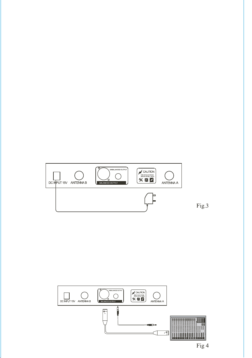
2.Power Input Connection:
Connect input connector of AC/DC adapter to power source. Connect
output connector to receiver rear panel DC input jack (8). Pay attention
to the power source voltage.
3.Audio Output Connection
(a) Unbalanced Output: Use attached audio cable to connect one end to
the unbalanced output jack (7) of the receiver. Connect the other end
to the "LINE-IN" input jack of amplifier.
(B) Balanced Output: Use "XLR" or "Cannon" type audio cable(not provided)
to connect one end to the balanced output jack (8)of the receiver. Connect
the other end to the "MIC IN" input jack of the mixer or amplifier.
2. INSTALLATION OF THE RECEIVER
3
Page 4

1. Pull out antenna A & B. Make them to be perpendicular with the machine.
2. Connect input connector of AC/DC adapter to power source. Connect
output connector to receiver rear panel DC input jack (8).
Make sure the power source voltage is same as marked voltage on the
rear panel
3. Connect one end of attached audio cable to the unbalanced output jack(7)
of the receiver. Connect the other end of the cable to "line in" input jack of
amplifier.
4. Turn on power switch, LCD panel will light.
5. Press UP or down button to set the receiver frequency same as transmitter
frequency.
6. Turn on transmitter power switch, "RF" indicator of the receiver will display
Volume of the receiver can be controlled by adjusting the volume knob.
Attention
When installing the receiver, locate the receiver at least 1m above the ground
and 1m beyond the wall. Antennae should be extended fully to get the
the reception signal.
3.OPERATION OF THE RECEIVER
4. TRANSMITTER PARTS DESCRIPTION
1. MIC head: capsule inside.
2. Power switch
3. LCD Display: display channel no., Frequency and battery life.
4. Channel Selector
5. Colorful ring. It is for distinguishing different microphones.
6. Battery compartment.
4
Page 5

6. OPERATION OF THE TRANSMITTER
1. Unscrew the battery compartment then put in a 9V battery.
Attention: The polarity should be right.
2.Turn on the transmitter. LCD panel will light. If LCD panel does not light,
check the battery to see if the voltage is low or the battery is not installed
correctly.
3. Press Up or Down to adjust frequency.
5. OPTIONAL TRANSMITTER/HEADSET MIC (171.335)
FREQUENCY & CHANNEL LISTING
Channel 01 = 863.350MHz
Channel 02 = 863.450MHz
Channel 03 = 863.550MHz
Channel 04 = 863.650MHz
Channel 05 = 863.750MHz
Channel 06 = 863.850MHz
Channel 07 = 863.950MHz
Channel 08 = 864.150MHz
Channel 09 = 864.250MHz
Channel 10 = 864.350MHz
Channel 11 = 864.450MHz
Channel 12 = 864.550MHz
Channel 13 = 864.650MHz
Channel 14 = 864.750MHz
Channel 15 = 864.850MHz
Channel 16 = 864.950MHz
5
Page 6

6. TROUBLESHOOTING
7.SPECIFICATION
1. Turn on the receiver, but the indicator does not light.
-Make sure the power cable is well fixed and the socket is in good condition.
-Check if the fuse is blown.
2. When you speak, the "AF" light twinkles but no sound output.
-Check if the volume is in lowest place or the audio cable is not fixed well.
3. The effective signal-receiving distance becomes close. And signal-receiving
is not well. Sound quality is bad.
-Check if the battery power is low. Change new battery.
-Check if there are same frequency signals in your surroundings.
* Do not use two units with the same frequency at the same time in a place.
(Separate them at least 120m.)
* Do not open and repair it when some serious breakdown happens.
* Please contact your local distributor for repair.
1.COMPREHENSIVE PERFORMANCE
2.RECEIVER
POWER SUPPLY: DC15V
CONSUME POWER: 5 WATER
SIGNAL/NOISE RATIO: MORE THAN 90dB
IMAGE & SPURIOUS REJECTION: MORE THAN 80dB
BORDER UPON CHANNEL REJECTION: MORE THAN 80dB
RECEIVING SENSITIVITY: LESS THAN 10dBu V(SINAD=30dB)
DE-EMPHASIS: 50µs
CARRIER FREQUENCY: UHF 863-865MHz
FREQUENCY STABILISATION: < 30ppm
DYNAMIC RANGE: MORE THAN 90dB
TOTAL HARMONIC DISTORTION: LESS THAN 0.5%
FREQUENCY RESPONSE: 40HZ-15KHZ 3dB
AUDIO OUTPUT LEVEL: UNBALANCED OUT: 0-- 400mV
BALANCED OUT: 0-- 200mV
6
Page 7

3.TRASNMITTER
8. IMPORTANT SAFEGUARDS
TRANSMITTING POWER: 8.5mW
MODULATION TYPE: FM, F3F
MAX DEVIATION: 25kHz
SPURIOUS EMISSION: >40dB (WITH CARRIER)
POWER SUPPLY: 9V battery
BATTERY LIFE: 6 hours (GP) 1604s 9V battery
NOISE CONTROL: perfect circuit for eliminating noise
1.The installation of receiver antenna influences the operating efficiency
of the receiver. Place receiver and microphone as short as possible for
better reception and performance.
2.The external DC power supply should not be below 12V. Otherwise it
would not work properly. If it is over 15V, some components of the
receiver will be damaged due to higher current. Use minimum 1A
power supply.
9. CAUTION
1.Avoid putting the main machine in a blind angle when it is used. This is to
keep signal reception in good condition.
2.Don't throw, fall, toss, cast the handheld microphone so as not to damage
it seriously.
3.Please keep the machine from direct sunshine or rains. Place it in a place
far away from the magnetic field.
4.Don't open it yourself because there is high voltage in it.
7
 Loading...