


CLP1200
POWERED MIXING CONSOLE
Item ref: 170.880UK User Manual

Caution: Please read this manual carefully before operating
Damage caused by misuse is not covered by the warranty
Introduction
Thank you for choosing the CLP1200 powered mixing console as part of your professional sound system. This product has been developed to provide a full arsenal of facilities and features to fulfill a comprehensive range of audio requirements with high quality, reliable results. Please read and keep this manual to achieve the best results from your purchase and avoid damage through misuse.
Package Contents
CLP1200 powered mixing console
MPR remote control
Mains lead(s)
User manual
If you find any accessory is missing or the product has arrived with any problems, please contact your retailer at once.
This product contains no user-serviceable parts so make no attempt to try to fix or modify this item yourself as this will invalidate the warranty. We recommend you keep the original package and proof of purchase for any possible replacement or return demand.
Warning
To prevent the risk of fire or electric shock, do not expose any of the components to rain or moisture.
If liquids are spilled on the console, stop using immediately, allow the unit to dry out and have checked by qualified personnel before further use.
Avoid impact or heavy vibration to any of the components.
No user serviceable parts inside - refer servicing to qualified service personnel.
Safety
Ensure that the correct mains lead is used with adequate current rating and that the mains voltage is as stated on the unit
Avoid ingress of water or particles into any part of the housing
Do not cover or obstruct cooling vents
Placement
Keep the console out of direct sunlight and away from heat sources.
Do not place heavy objects on top of the control surface
If rack-mounting, use the correct rack-ears and ensure adequate support for the weight of the product.
Allow adequate space for air-flow and keep the console away from damp or dusty environments.
Cleaning
Use a soft dry or slightly damp cloth top clean surfaces of the console
A soft brush can be used to clear debris from between controls without damaging them
To avoid damage, do not use solvents to clean the components
170.880UK User Manual

Console layout
The CLP1200 has comprehensive input and output sections which can be split further into various stages of processing and routing. All preamps have studio grade, low noise architecture for the cleanest possible path throughout the signal chain. The input stages are repeated across each channel of the console, which simplifies operation and enables quick and easy location of various controls. The following pages of this manual are divided up into these stages to explain the details and function of each control.
170.880UK User Manual
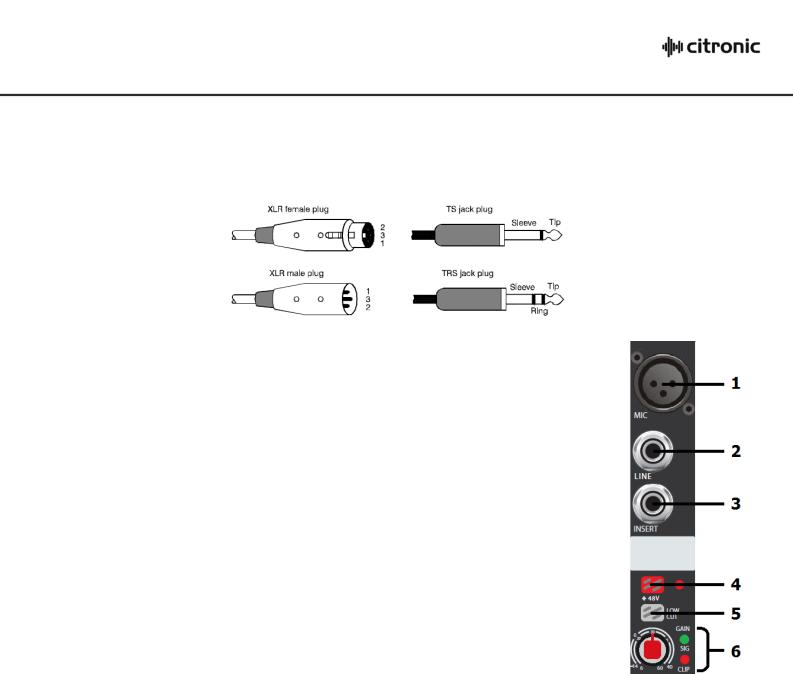
Mic/Line Input Section
Channel inputs and inserts are provided as XLR and/or 6.3mm jack sockets.
The connections for these inputs are assigned as follows.
1. |
MIC input |
Connect a balanced microphone to this XLRF input. An unbalanced |
||||||
|
|
microphone can be connected provided that +48V phantom power |
||||||
|
|
is not used. Wired as follows. |
|
|
|
|||
|
|
|
|
|
|
|
|
|
|
Balanced |
|
Pin 1 = Ground |
Pin 2 = Signal + |
Pin 3 |
= Signal – |
|
|
|
Unbalanced |
|
Pin 1 = Ground |
Pin 2 = Signal + |
Pin 3 |
= Ground |
|
|
2. |
LINE input |
Connect balanced or unbalanced line level signals to this 6.3mm |
||||||
|
|
TRS jack input. Wired as follows. |
|
|
|
|||
|
|
|
|
|
|
|
|
|
|
Balanced |
|
Tip = |
Signal + |
Ring = Signal – |
Sleeve = Ground |
|
|
|
Unbalanced |
|
Tip = |
Signal + |
- |
Sleeve = Ground |
|
|
3.Channel INSERT The channel signal can be diverted for external processing and
returned back to the channel by connecting a TRS jack to 2 x mono jack lead to this connector.
The channel inserts are post Low Cut but are pre-EQ. Wired as follows.
TRS jack |
Tip = |
Send |
Ring = Return |
Sleeve = Ground |
Left mono jack |
Tip = |
Send |
- |
Sleeve = Ground |
Right mono jack |
Tip = |
Return |
- |
Sleeve = Ground |
4. |
+48V Phantom |
Press in this switch to apply +48Vdc voltage to the XLR input condenser |
|
|
microphones and D.I. boxes which require phantom power |
5. |
LOW CUT |
Press in this switch to apply a 75Hz 18dB/oct low frequency roll-off filter which |
|
|
can help to reduce popping, rumble and handling noise from vocal microphones. |
6. |
GAIN control |
This control trims the input signal to the optimum level for the channel strip circuitry. |
|
|
Too low a signal level can result in a weak signal-to-noise ratio and too high can result |
|
|
in overload and distortion in the signal output. |
The adjacent SIG and CLIP LEDs will give an indication of the signal level.
Ideally, the Gain rotary control should be adjusted so that the green SIG LED is lit and the loudest passages of the input signal (e.g. bass drum beats) will just momentarily trigger the CLIP LED. Anything longer than a momentary flicker of the CLIP LED means that the Gain should be reduced. Using the PFL button further down the channel strip gives a more detailed view of the channel level on the main VU LEDs.
170.880UK User Manual
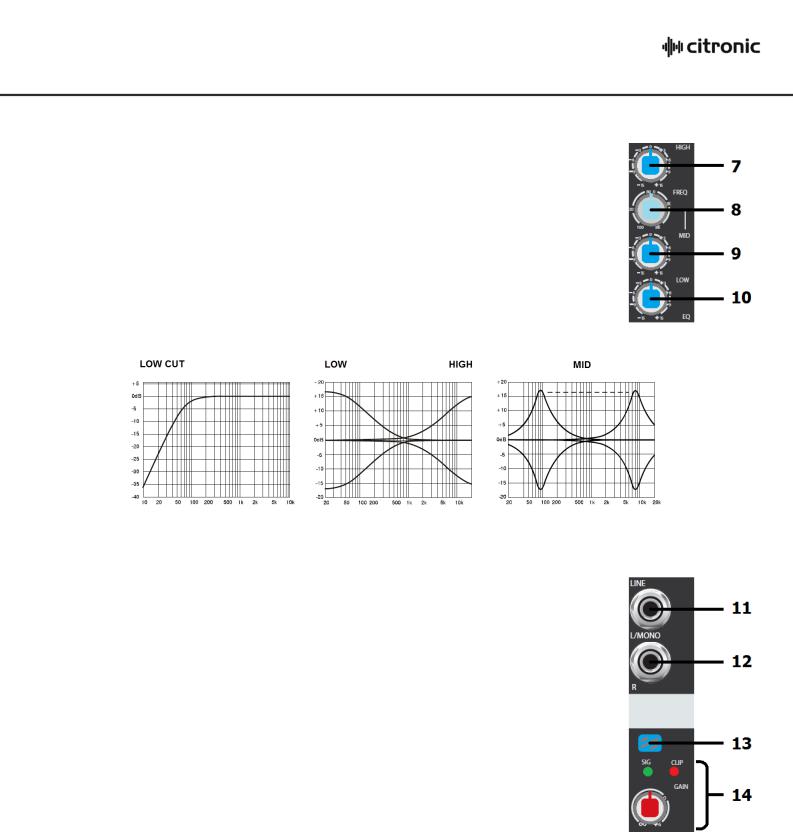
Mic/Line EQ Section
7. |
HIGH |
This control can boost or cut the high frequencies (centre 12kHz) |
|
|
by ±15dB (12 o’clock position is zero) |
8. |
FREQ |
This control sweeps the frequency band affected by the MID |
|
|
control with centre frequency from 100Hz through to 8kHz |
9. |
MID |
This control can boost or cut the mid frequencies set using the |
|
|
FREQ control by ±15dB (12 o’clock position is zero) |
10. |
LOW |
This control can boost or cut the low frequencies (centre 80Hz) |
|
|
by ±15dB (12 o’clock position is zero) |
Stereo Line Input Section
11. |
LINE L/MONO |
Connect a balanced or unbalanced line level signal to this 6.3mm |
||||||
|
|
|
TRS jack input. Wired as follows. |
|
|
|||
|
|
|
|
|
|
|
|
|
|
|
Balanced |
|
Tip = |
Signal + |
Ring = Signal – |
Sleeve = Ground |
|
|
|
Unbalanced |
|
Tip = |
Signal + |
- |
Sleeve = Ground |
|
12. |
LINE R |
For stereo line inputs, use this connector for Right input and the |
||||||
|
|
|
above connector for Left input. All following channel controls will |
|||||
|
|
|
affect both signals but Left & Right signals will remain separate. |
|||||
13. |
ST1/PC |
Switches the channel input between ST1 and the PC interface |
||||||
|
|
|
Press this switch in to override the ST1 inputs and the channel |
|||||
|
|
|
will be fed from a PC or Mac connected to the USB B connector. |
|||||
13. |
ST2/MPR |
Switches the channel input between ST2 and the MPR player. |
||||||
|
|
|
Press this switch in to override the ST2 inputs and the channel |
|||||
|
|
|
will be fed from playback of USB or SD media via the MPR. |
|||||
14. |
GAIN control |
This control trims the mono or stereo input to the optimum level for the channel strip. |
||||||
|
|
|
Too low a signal level can result in a weak signal-to-noise ratio and too high can result |
|||||
in overload and distortion in the signal output.
The SIG and CLIP LEDs above the rotary control give an indication of the signal level. Ideally, the Gain rotary control should be adjusted so that the green SIG LED is lit and the loudest passages of the input signal (e.g. bass drum beats) will just momentarily trigger the CLIP LED. Anything longer than a momentary flicker of the CLIP LED means that the Gain should be reduced.
Using the PFL button further down the channel strip gives a more detailed view of the channel level on the main VU LEDs.
170.880UK User Manual
 Loading...