

Page 1

PRIVATE CARS
XANTIA-XM-SYNERGIE
CAR 050008
Book 2
«The technical information contained in this document is intended for the exclusive use of the trained personnel of the
motor vehicle repair trade. In some instances, this information could concern the security and safety of the vehicle. The
information is to be used by the professional vehicle repairers for whom it is intended and they alone would assume full
responsibility to the exclusion of that of the manufacturer».
’’The technical information appearing in this brochure is subject to updating as the characteristics of each
model in the range evolve. Motor vehicle repairers are invited to contact the CITROËN network periodically
for further information and to obtain any possible updates».
2001
Page 2

PRESENTATION
THIS HANDBOOK summarises the characteristics, adjustments, checks and special features of CITROEN vehicles, not including COMMERCIAL
vehicles for which there exists a separate handbook.
The handbook is divided into the following groups representing the main functions :
GENERAL - ENGINE - INJECTION - IGNITION - CLUTCH, GEARBOX, DRIVESHAFTS - AXLES, SUSPENSION, STEERING - BRAKES -
HYDRAULICS - ELECTRICAL - AIR CONDITIONING.
In each section, the vehicles are dealt with in the following order : XANTIA-XM-SYNERGIE and all models where applicable.
The information given in this handbook is based on vehicles marketed in EUROPE.
Page 3

IMPORTANT
If you find that this handbook does not always meet your requirements, we invite you to send us your suggestions which we will take into account
when preparing future publications. For example :
– INSUFFICIENT INFORMATION
– SUPERFLUOUS INFORMATION
– NEED FOR MORE DETAILS
Please send your comments and suggestions to :
CITROEN U.K. Ltd.
221, Bath Road,
SLOUGH,
SL1 4BA.
U.K.
Page 4
XANTIA
Parking brake 240 - 241
Bleed of brakes
242
XM
Parking brake
244
Bleed of brakes
245
SYNERGIE Parking brake 249
SUSPENSION
De-pressurising 250 - 260
HYDRAULICS
Pneumatic
XANTIA 261 - 265
units
XM 266 - 269
ELECTRICITY
Starter motors 270 - 272
Alternators 273 - 279
Charging circuit 280
Preheater plugs 281
AIR CONDITIONING
R 134 a quantities 282
Special features 283 - 288
Checking temperatures 289 - 290
Checking pressures 291
XANTIA 293 - 297
XM 298 - 301
SYNERGIE 302 - 303
INDEX
GENERAL
XANTIA 1 - 8
XM 9 - 13
SYNERGIE 14 - 15
XANTIA 17 - 18
XM 19
SYNERGIE 20
Lubricants 21 - 34
ENGINE
Specifications 36 - 38
Cyl. head marking and tightening 51 - 61
Auxiliary equipment drive belt 62 - 78
Checking and setting valve timing 83 - 84
Valve clearances 121
Oil pressure 122
Oil filter 125
INJECTION
Idling, anti-pollution 127
Petrol injection 128 - 129
Anti-pollution technical checks 130
Emission standards 131 - 137
LPG safety requirements 138 - 142
Identification
of vehicles
Capacities
Axle
geometry
Brake specifications
Aircon
system
HDi safety requirements 143 - 146
Checks: HDi fuel circuit 147 - 148
Checks: HDi air circuit 149
Checks: Turbo pressure 150 - 151
Checks: HDi exhaust gas recycling 152
DELPHI checking, timing 153 - 156
BOSCH checking, timing 157 - 163
IGNITION
Sparking plugs 164
CLUTCH-GEARBOX-DRIVESHAFTS
Speedometer 165
Clutch adjustments 169 - 176
Driveshafts 214
AXLES-SUSPENSION-STEERING
XANTIA 215 - 223
XM 224 - 230
SYNERGIE 231 - 236
BRAKES
XANTIA 237 - 238
XM 243
SYNERGIE 246
Page 5

PRESENTATION
THIS HANDBOOK summarises the characteristics, adjustments, checks and special features of CITROEN vehicles, not including COMMERCIAL
vehicles for which there exists a separate handbook.
The handbook is divided into the following groups representing the main functions :
GENERAL - ENGINE - INJECTION - IGNITION - CLUTCH, GEARBOX, DRIVESHAFTS - AXLES, SUSPENSION, STEERING - BRAKES -
HYDRAULICS - ELECTRICAL - AIR CONDITIONING.
In each section, the vehicles are dealt with in the following order : XANTIA-XM-SYNERGIE and all models where applicable.
The information given in this handbook is based on vehicles marketed in EUROPE.
Page 6

IMPORTANT
If you find that this handbook does not always meet your requirements, we invite you to send us your suggestions which we will take into account
when preparing future publications. For example :
– INSUFFICIENT INFORMATION
– SUPERFLUOUS INFORMATION
– NEED FOR MORE DETAILS
Please send your comments and suggestions to :
CITROEN U.K. Ltd.
221, Bath Road,
SLOUGH,
SL1 4BA.
U.K.
Page 7

XANTIA
Parking brake 240 - 241
Bleed of brakes
242
XM
Parking brake
244
Bleed of brakes
245
SYNERGIE Parking brake 249
SUSPENSION
De-pressurising 250 - 260
HYDRAULICS
Pneumatic
XANTIA 261 - 265
units
XM 266 - 269
ELECTRICITY
Starter motors 270 - 272
Alternators 273 - 279
Charging circuit 280
Preheater plugs 281
AIR CONDITIONING
R 134 a quantities 282
Special features 283 - 288
Checking temperatures 289 - 290
Checking pressures 291
XANTIA 293 - 297
XM 298 - 301
SYNERGIE 302 - 303
INDEX
GENERAL
XANTIA 1 - 8
XM 9 - 13
SYNERGIE 14 - 15
XANTIA 17 - 18
XM 19
SYNERGIE 20
Lubricants 21 - 34
ENGINE
Specifications 36 - 38
Cyl. head marking and tightening 51 - 61
Auxiliary equipment drive belt 62 - 78
Checking and setting valve timing 83 - 84
Valve clearances 121
Oil pressure 122
Oil filter 125
INJECTION
Idling, anti-pollution 127
Petrol injection 128 - 129
Anti-pollution technical checks 130
Emission standards 131 - 137
LPG safety requirements 138 - 142
Identification
of vehicles
Capacities
Axle
geometry
Brake specifications
Aircon
system
HDi safety requirements 143 - 146
Checks: HDi fuel circuit 147 - 148
Checks: HDi air circuit 149
Checks: Turbo pressure 150 - 151
Checks: HDi exhaust gas recycling 152
DELPHI checking, timing 153 - 156
BOSCH checking, timing 157 - 163
IGNITION
Sparking plugs 164
CLUTCH-GEARBOX-DRIVESHAFTS
Speedometer 165
Clutch adjustments 169 - 176
Driveshafts 214
AXLES-SUSPENSION-STEERING
XANTIA 215 - 223
XM 224 - 230
SYNERGIE 231 - 236
BRAKES
XANTIA 237 - 238
XM 243
SYNERGIE 246
Page 8
GENERALGENERAL
1
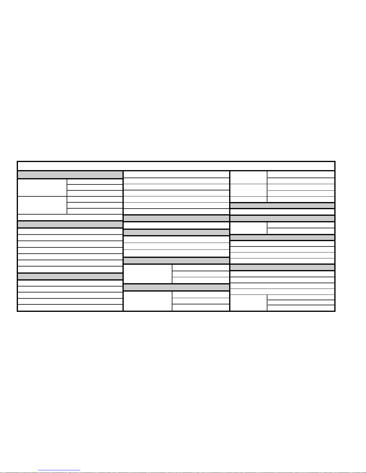
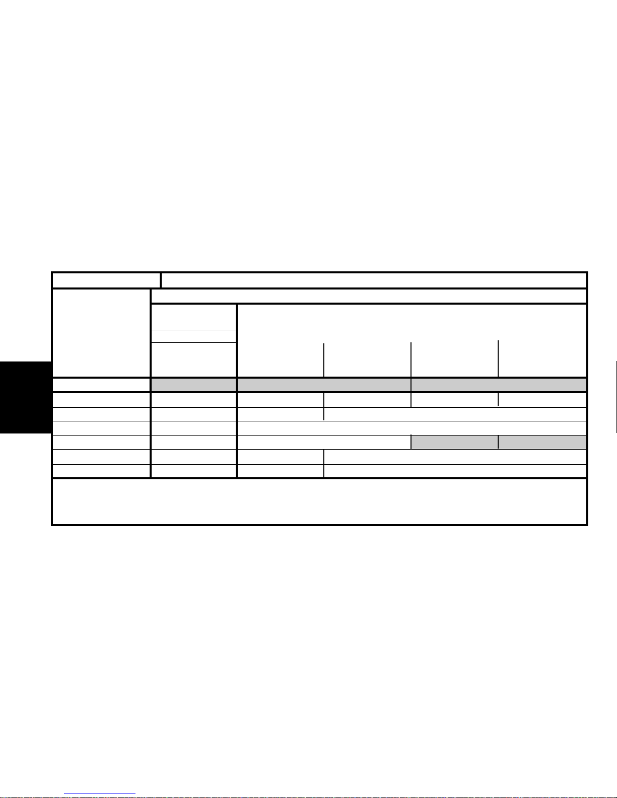
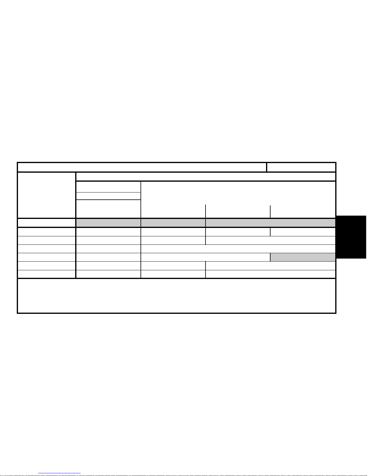
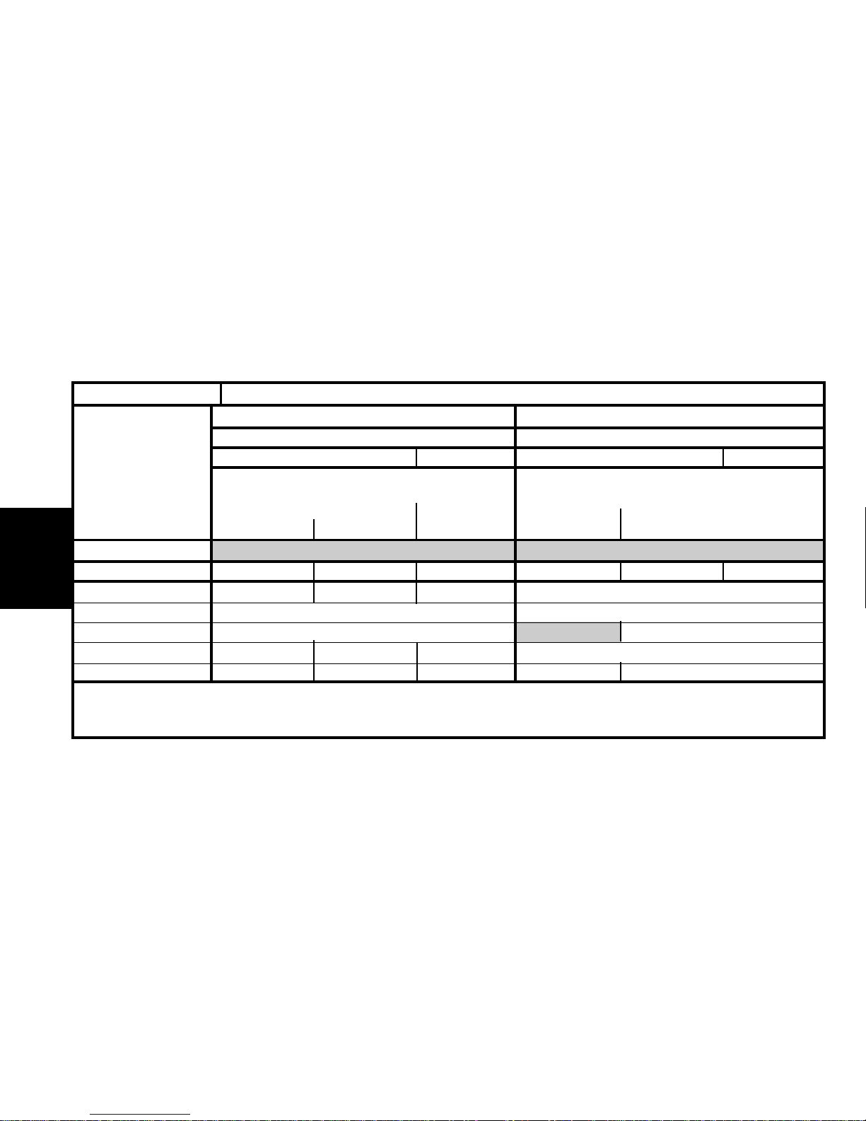
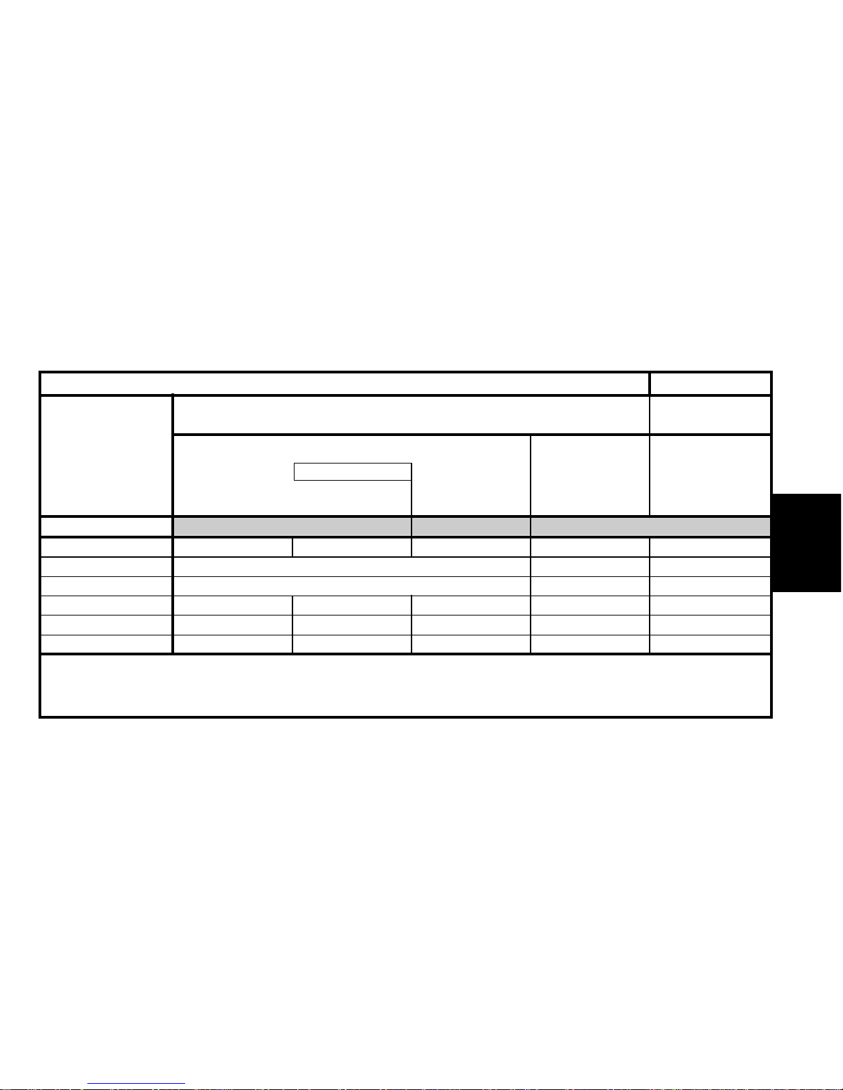
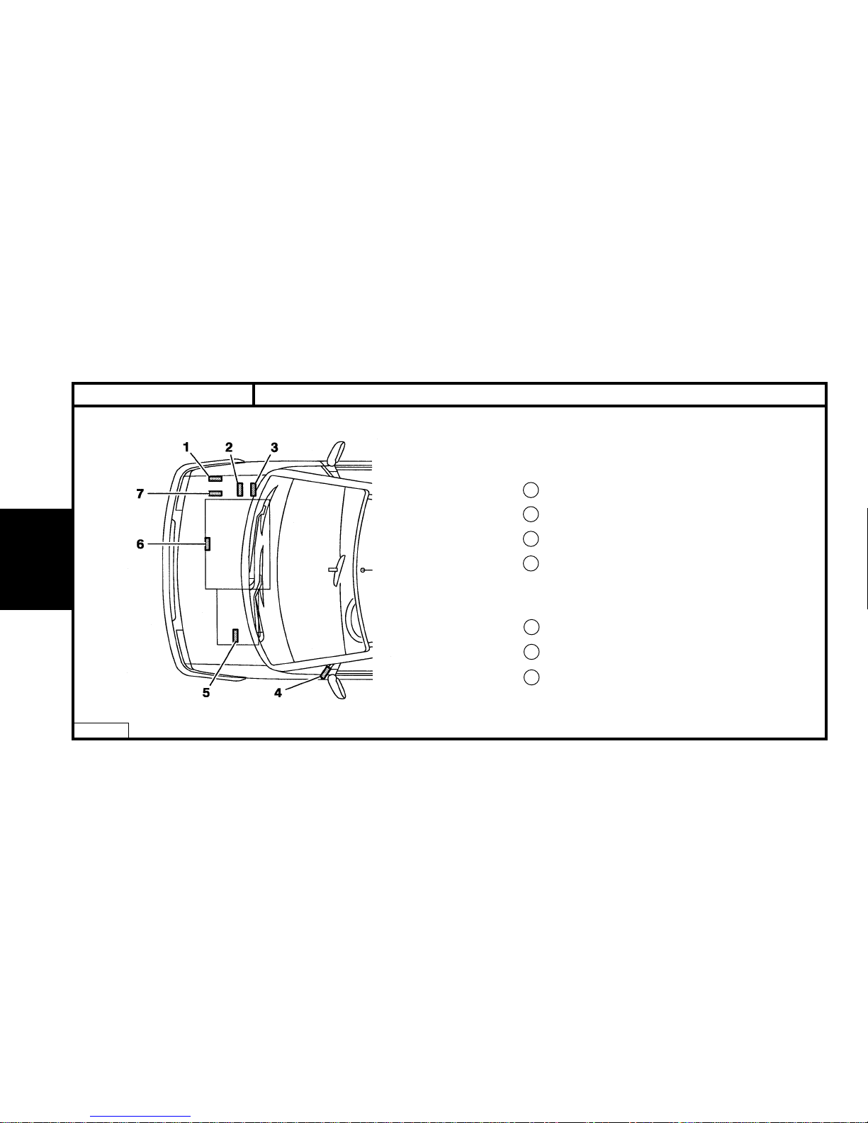
XANTIA - All TypesIDENTIFICATION OF VEHICLES
E1AP07ED
1 Manufacturer’s cold stamp.
2 R.P. organisation N°.
3 Paint code.
4 01/02/99 # Label :
- Pression de gonflage.
- N° organisation P.R.
- Code peinture
5 Automatic gearbox identification ref.
6 Manual gearbox identification ref.
7 Manufacturer’s name plate.
8 XU5 - XU7 - ES9J4 engine plate.
9 XU10 - XUD engine plate.
Page 9
GENERAL
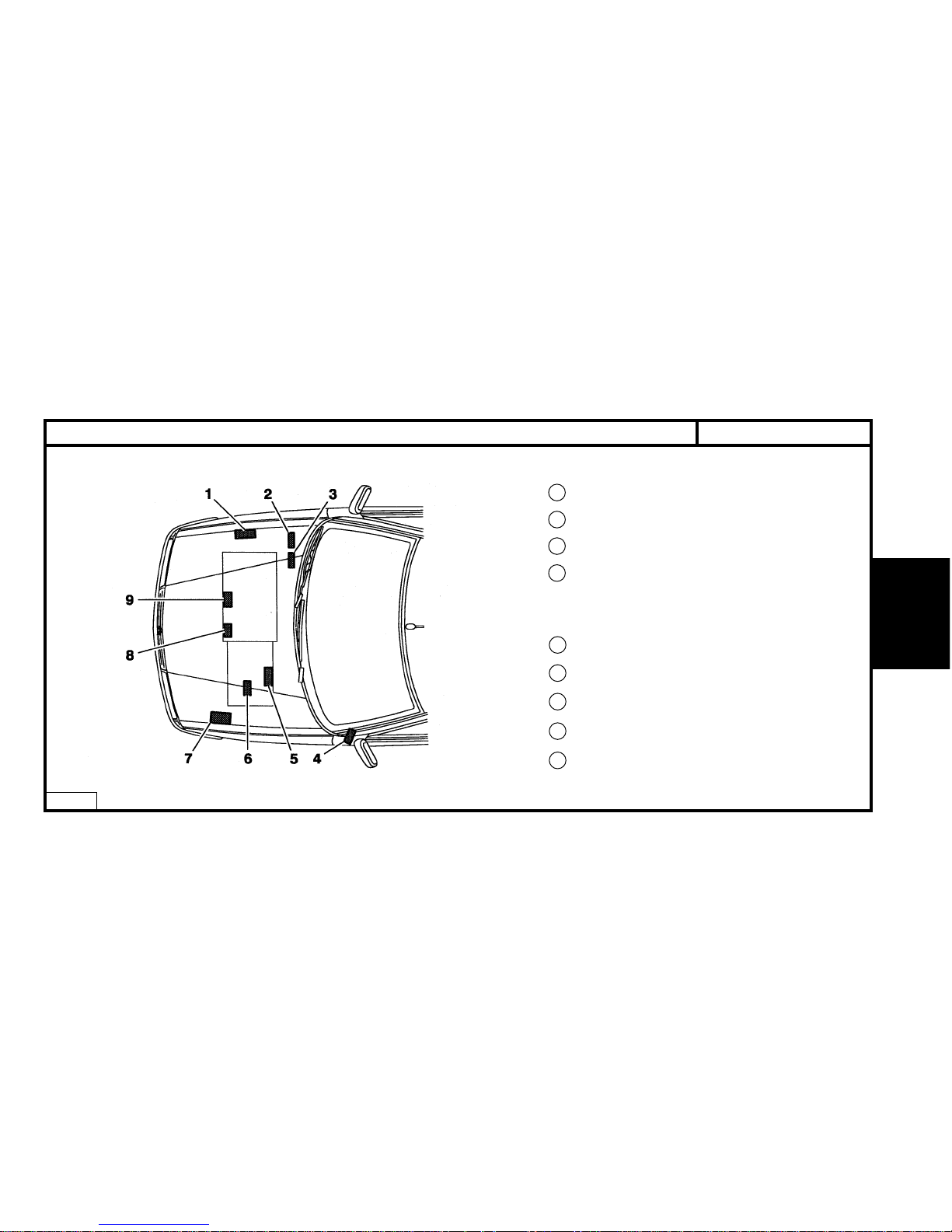
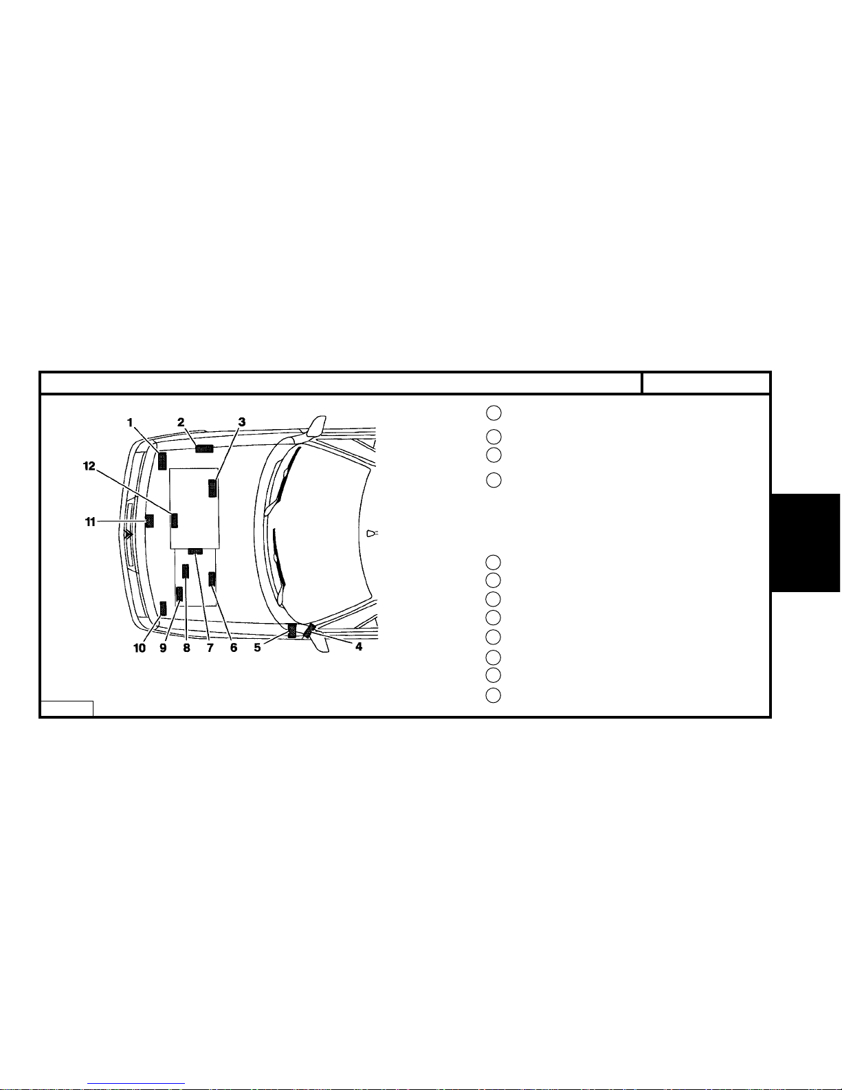
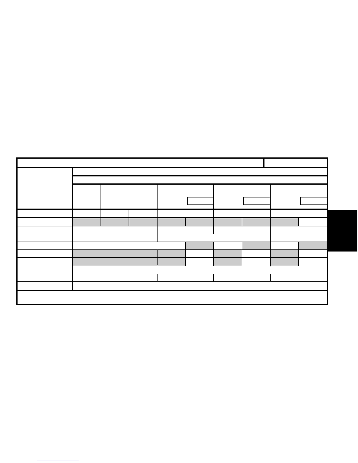
X1 BFZF X1 BFXF X1 LFYM X1 LFYF X1 LFYN X1 LFYB
BFZ BFX LFY
1580 1761
78
BE3/5 AL4 BE3/5 AL4 BE3/5
20 TE 00 20 TE 35 20 TP 52 20 TE 35 (*) 20 TP 52 20 TE 36
Emission standard L3 L4
Type code
Engine type
Cubic capacity (cc)
Fiscal rating (hp)
Gearbox type
Gearbox ident. plate
2
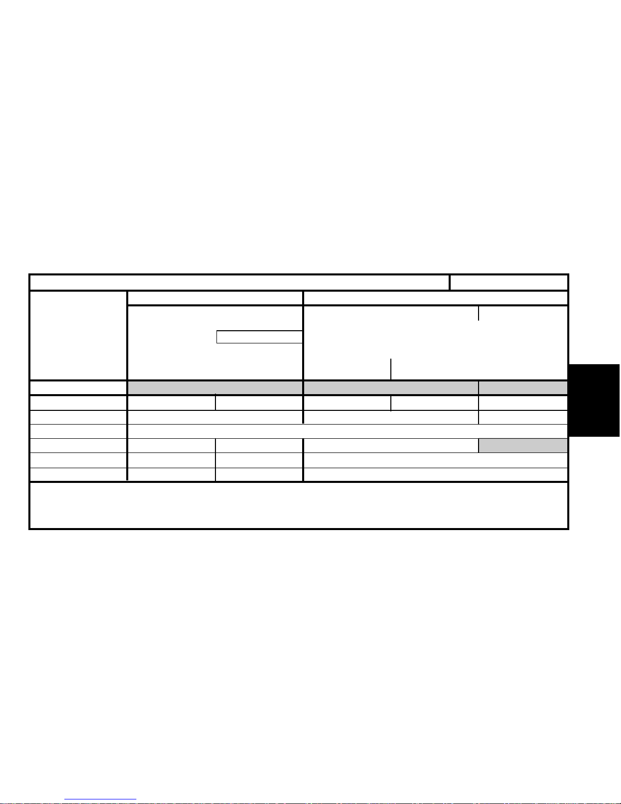
XANTIA - All Types
IDENTIFICATION OF VEHICLES
PETROL SALOON
SX SX
1.6 i 1.8 i
SX
1.8 i 16 V
Auto.
Auto.
(*) = Long gearbox.
Page 10
GENERALGENERAL
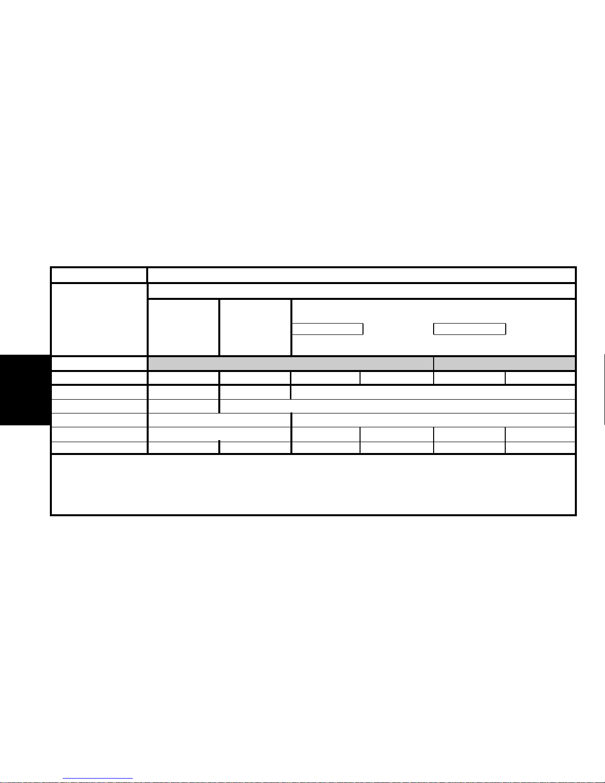
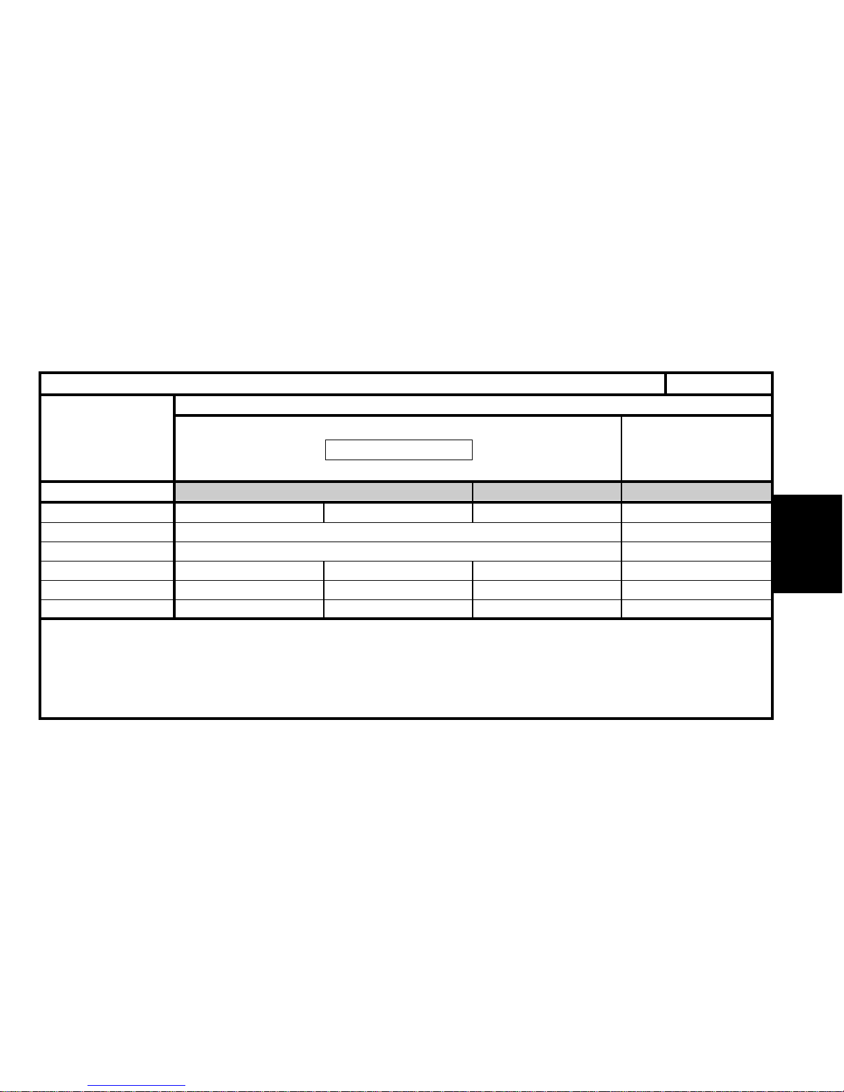
Emission standard L4 L3
Type code
Engine type
Cubic capacity (cc)
Fiscal rating (hp)
Gearbox type
Gearbox ident. plate
3
X1 LFYN/IF (*) X1 LFYB/IF (*) X1 RFVM X1 RFVF X7 XFZF X7 XFZM
LFY RFV XFZ
1761 1998 2946
91314
AL4 BE3/5 AL4 BE3/5 ML/5 4HP20
20 TP 52 20 TE 36 20 TE 53 20 TE 37 20 LE 89 20 HZ XX
XANTIA - All TypesIDENTIFICATION OF VEHICLES
PETROL SALOON
1.8i 16 V
SX SX
Exclusive Activa
SX
Exclusive
2.0i 16 V 30.i V6
(*) = IF = Fiscal incentive.
Page 11
GENERAL
4
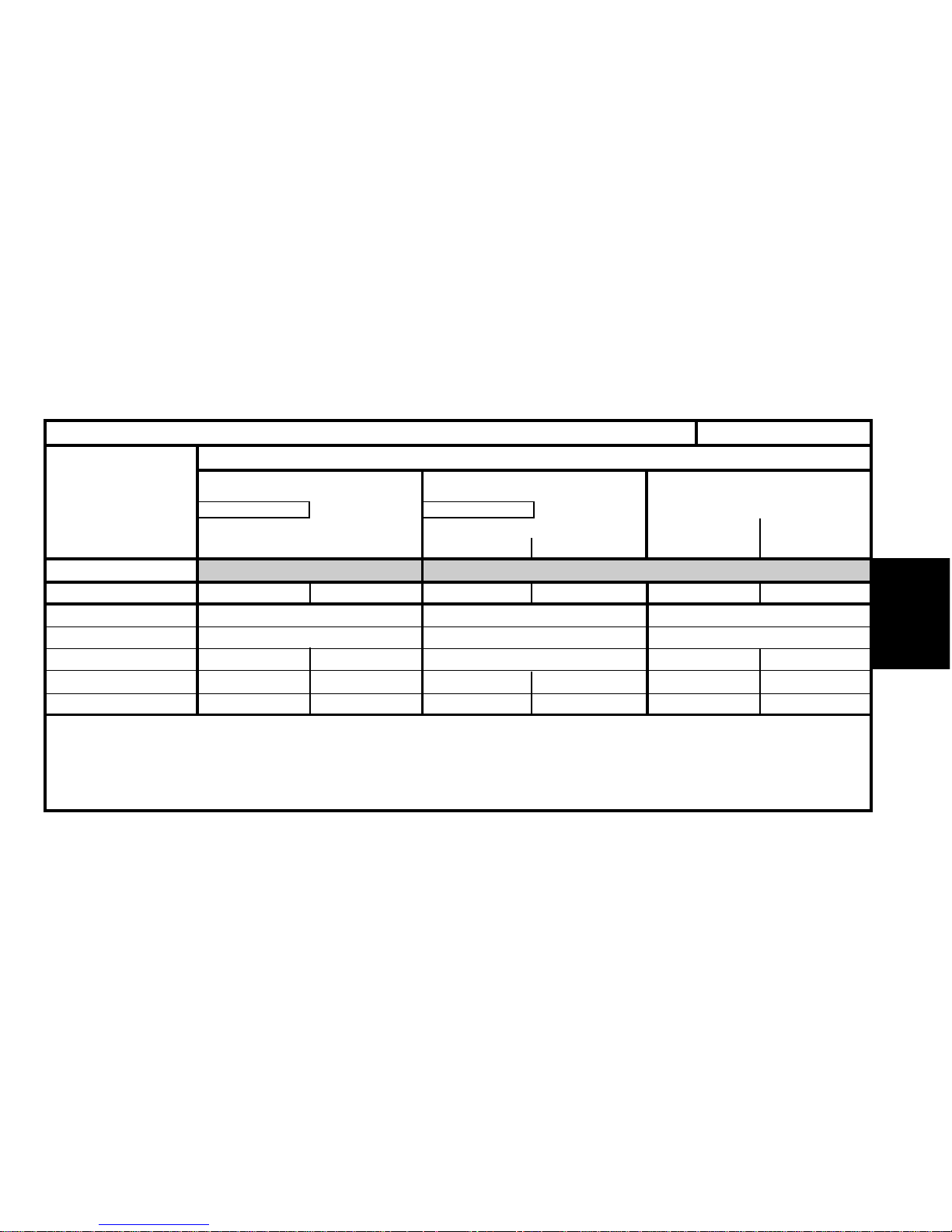
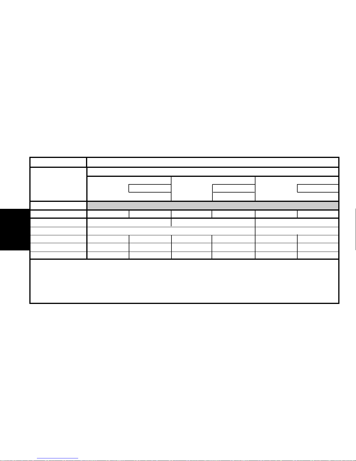
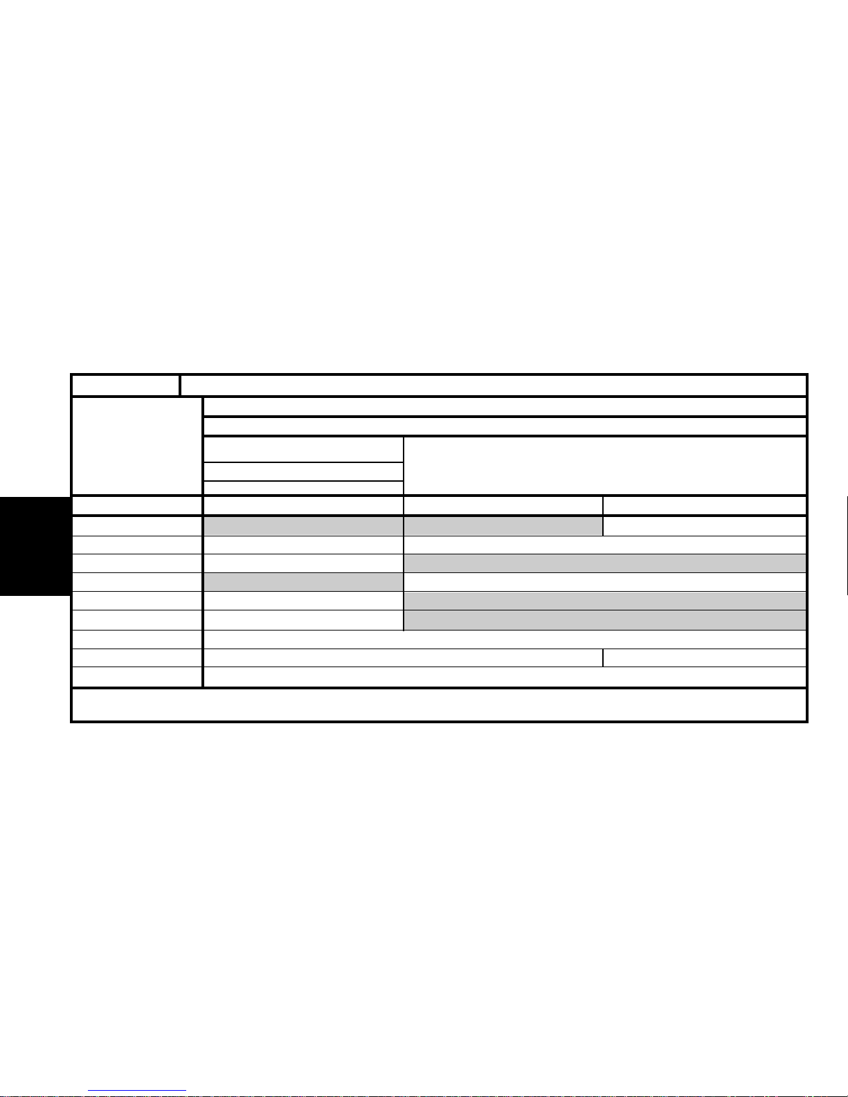
Emission standard L3 L3 L4
Type code
Engine type
Cubic capacity (cc)
Fiscal rating (hp)
Gearbox type
Gearbox ident. plate
X1 DHXM X1 RFYF X1 RHZF X1 RHZB X7 RHZB
DHX RHY RHZ
1905 1997
76
AL4 BE3/5 ML/5
20 TP 50 20 TE 40 20 LE 84
IDENTIFICATION OF VEHICLESXANTIA - All Types
DIESEL SALOON
2.0 HDi (1)
SX
Activa
SX - SX Aircon Pack
Exclusive
Activa
SX
Exclusive
1.9 D
Auto.
SX
SX Aircon Pack
SX
SX Aircon Pack
(1) HDi = High pressure Diesel injection
Page 12
GENERALGENERAL
5
Emission standard L3 L3 L4
Type code
Engine type
Cubic capacity (cc)
Fiscal rating (hp)
Gearbox type
Gearbox ident. plate
X2 LFXF X2 LFYF X2 LFYC X2 LFYB/IF (*) X2 LFYB
LFX LFY
1761
787
BE3/5
20TE 35 20 TE 36 20 TE 35 20 TE 36
IDENTIFICATION OF VEHICLES XANTIA - All Types
PETROL ESTATE
1.8i 16V
SX
1.8i
SX
(*) = IF = Fiscal incentive.
SX - SX Aircon Pack
Page 13
GENERAL
6
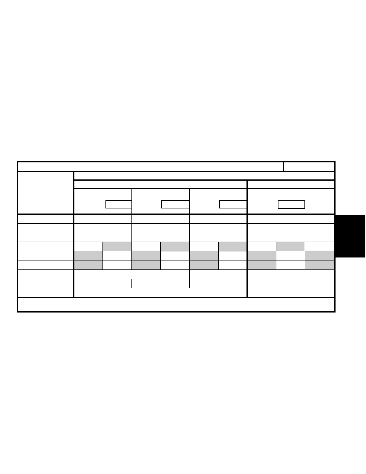
X2 RFVM X2 RFVF X2 RFVM X2 XFZF X7 XFZM
RFV XFZ
1998 2946
9 9 14 13
AL4 BE3/5 4HP20 ML/5
20 TP 53 20 TE 37 20 HZ XX 20 LE 89
Emission standard L3
Type code
Engine type
Cubic capacity (cc)
Fiscal rating (hp)
Gearbox type
Gearbox ident. plate
XANTIA - All Types
IDENTIFICATION OF VEHICLES
PETROL ESTATE
3.0i V6
SX Aircon Pack
Exclusive Exclusive
SX
2.0i 16V
Auto.
Auto.
SX Aircon Pack
Exclusive
SX
Page 14
GENERALGENERAL
7
L3 L3 L4
X2 DHXM X2 RHYF X2 RHZF X2 RHZB
DHX RHY RHZ
1905 1997
76
AL4 BE3/5 ML/5
20 TP 50 20 TE 40 20 LE 84
XANTIA - All Types
IDENTIFICATION OF VEHICLES
DIESEL ESTATE
1.9 TD
2.0 HDi (*)
SX
SX Aircon Pack
SX
SX Aircon Pack
SX - SX Aircon Pack
Exclusive
SX
Exclusive
Auto.
Emission standard
Type code
Engine type
Cubic capacity (cc)
Fiscal rating (hp)
Gearbox type
Gearbox ident. plate
(1) HDi = High pressure Diesel injection
Page 15
GENERAL
Petrol
8
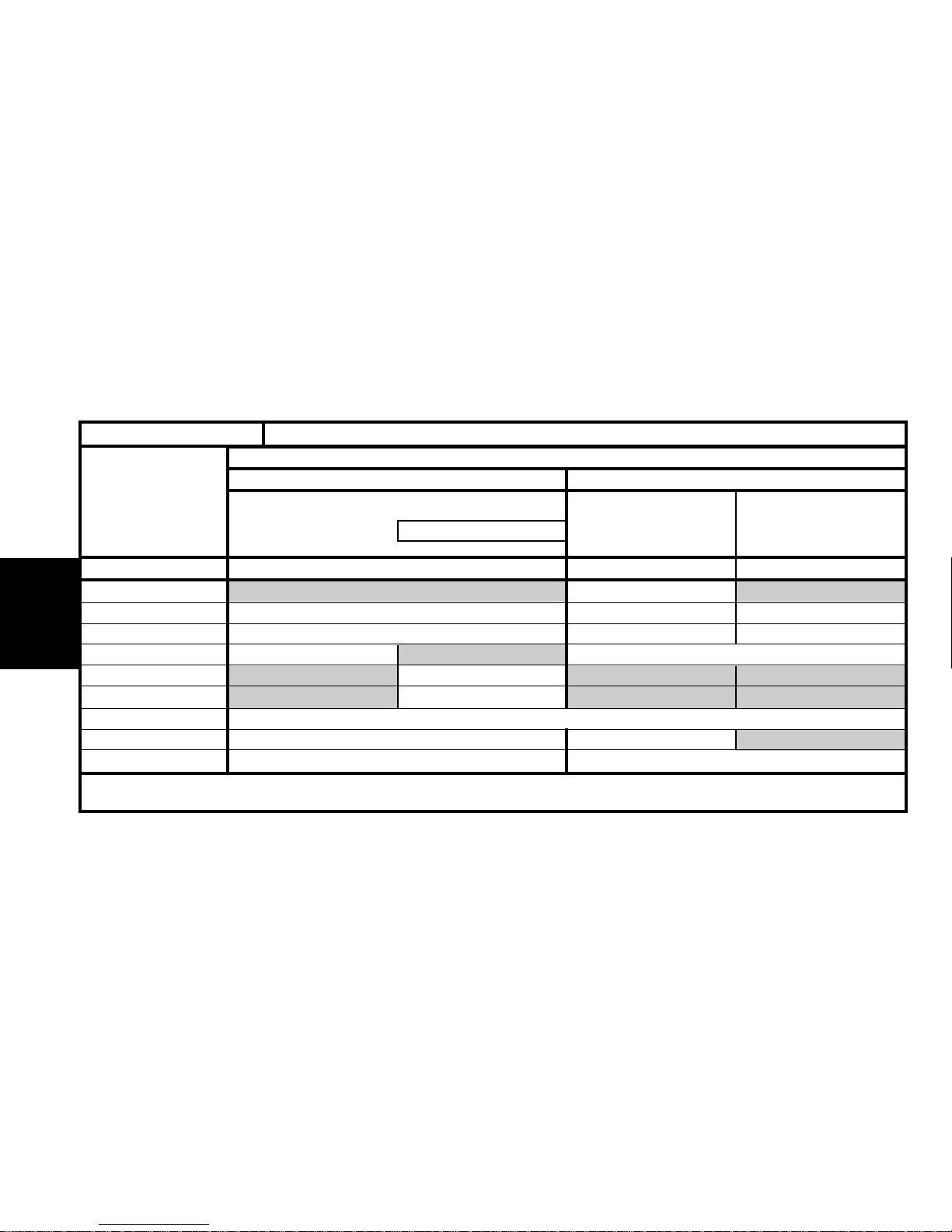
Emission standard L3 L3
Type code
Engine type
Cubic capacity (cc)
Fiscal rating (hp)
Gearbox type
Gearbox ident. plate
X1 RHYF X1 RHZF X2 RHYF/T (3) X1 LFYC/GPL X1 LFYC/GPL X2 LFYC/GPL
RHY RHZ RHY LFY/GPL
1997 1761
67
BE3/5 ML/5 BE3/5 BE3/5
20 TE 40 20 LE 84 20 TE 40 20 TE 36 20 TE 35
XANTIA - All Types
IDENTIFICATION OF VEHICLES
DUAL FUEL PETROL/LPG (1)COMMERCIAL VERSIONS ALL TYPES
Estate
2.0HDi (2)
SX Ambulance
SX Company
SX Entreprise SX
SX
SX Aircon Pack
X - SX Company
Diesel
Saloon Saloon
1.8i 16V
Estate
(1) = Liquid Petroleum Gas.
(2) HDi = High pressure Diesel injection.
(3) /T = Can be converted.
Page 16
GENERALGENERAL
9
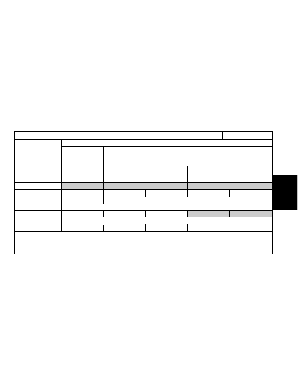
5 R.P. organisation N°. # 01/02/99 (
*
)
6 BE3 gearbox ident.
7 4HP 18 gearbox ident.
8 MG gearbox ident.
9 ME5T gearbox ident.
10 Paint code # 01/02/99 (*)
11 Manufacturer’s plate
12 4 cyl. engine plate
XM - All Types
IDENTIFICATION OF VEHICLES
1 Bodyshell N°
2 Manufacturer’s cold stamp
3 6 cyl. engine plate
4 R.P. organisation N°. (*) 01/02/1999 #
Label :
- Tyre pressures.
- R.P. organisation N°.
- Paint code
E1AP07FD
(*) : Applicable only to 1999 model year saloons
Page 17

GENERAL
3.0i V6
10
Emission standard L3
Type code
Engine type
Cubic capacity (cc)
Fiscal rating (hp)
Gearbox type
Gearbox ident. plate
Y4-CZ Y4-TV Y4-GG Y4-TT Y4-WG Y4-WH
RFV RGX XFZ
1998 2946
910 111314
BE3/5 4 HP 18 ME/5 4 HP 18 ML/5 4 HP20
20 TD 01 20 GZ 5G 20 GM 32 20 GZ 1G 20 LE 59 20 HZ YY
IDENTIFICATION OF VEHICLES
PETROL SALOON
2.0i 16 V
Auto.
Auto. Auto.
SX SX
SX - Exclusive
2.0i Turbo CT
XM - All Types
Page 18
GENERALGENERAL
L3 L4 L3
Y4-GZ Y4-RN Y4-WE Y4-NZ
P8C THY
2088 2446
78 79
ME/5 4 HP 18 ME/5 MG/5
20 GM 31 20 GZ 5D 20 GM 31 20 KM 70
11
XM Diesel
IDENTIFICATION OF VEHICLES
DIESEL SALOON
2.1 TD 2.5 TD
SX - ExclusiveSX
Auto.
Emission standard
Type code
Engine type
Cubic capacity (cc)
Fiscal rating (hp)
Gearbox type
Gearbox ident. plate
Page 19
GENERAL
12
Emission standard L3
Type code
Engine type
Cubic capacity (cc)
Fiscal rating (hp)
Gearbox type
Gearbox ident. plate
Y4-GB Y4-TU Y4-GM Y4-TS Y4-WJ Y4-TN
RFV RGX XFZ
1998 2946
9 10 9 10 13 14
BE3/5 4 HP 18 ME/5 4 HP 18 ML/5 4 HP 20
20 GM 36 20 GZ 5G 20 GM 33 20 GZ 1G 20 LE 59 20 HZ YY
XM - All Types IDENTIFICATION OF VEHICLES
PETROL ESTATE
2.0i 2.0i Turbo CT 3.0i V6
Auto.Auto.Auto.
SX SXSX-Commerce
SX
Page 20
GENERALGENERAL
Emission standard L3 L4 L3
Type code
Engine type
Cubic capacity (cc)
Fiscal rating (hp)
Gearbox type
Gearbox ident. plate
13
Y4-MZ Y4-CW Y4-WF Y4-RM Y4-GZ
P8C THY P8C
2088 2446 2088
787 97
ME/5 4 HP 18 ME/5 MG/5 ME/5
20 GM 31 20 GZ 5D 20 GM 31 20 KM 70 20 GM 31
IDENTIFICATION OF VEHICLES XM - All Types
Commercial EstateDIESEL ESTATE
2.1 TD
SX
Ambulance
2.5 TD
SX
Commerce
2.1 TD
Auto.
SX
SX
Commerce
Page 21
GENERAL
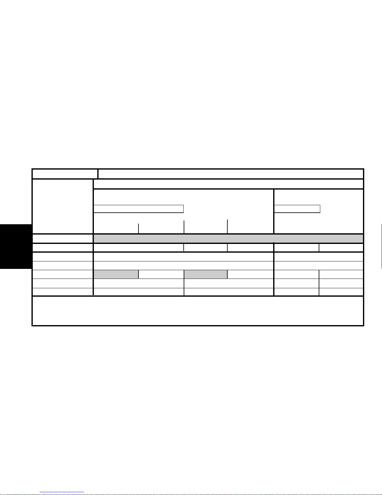
14
IDENTIFICATION OF VEHICLES
1 Manufacturer’s cold stamp
2 R.P. organisation No.
3 Paint code
4 01/02/99 # Label :
- Tyre pressures.
- R.P. Organisation No.
- Paint code.
5 Gearbox ident.
6 Engine plate
7 Manufacturer’s plate
SYNERGIE - All Types
E1AP07GD
Page 22
15
GENERALGENERAL
Emission standard IF L5 (*) L3 L4
Type code
Engine type
Cubic capacity (cc)
Fiscal rating (hp)
Gearbox type
Gearbox ident. plate
AF RFNC/IF AF RFNF/IF AF RHZA/T AF RHZA AF RHWB
RFN RHZ RHW
1997
910 6
BE4/5 AL4 ML5
DL26 - DL27 20 TP 31 20 LE 91
IDENTIFICATION OF VEHICLES
SYNERGIE - All Types
2.0 16 V HDi
2.0 HDi
X – SX
X Taxi – SX
Exclusive
2.0i 16 V
X – SX
Exclusive
DIESELPETROL
Auto.
Page 23
GENERAL
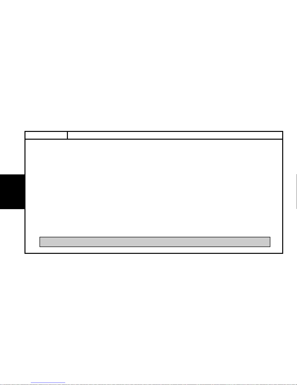
CAPACITIES
16
Draining method.
The oil capacities are defined according to the following methods.
1) - Vehicle on level surface (in high position, if equipped with hydropneumatic suspension).
2) - Engine warm (oil temperature 80°C).
3) - Draining of the oil sump + removal of the cartridge (duration of draining + dripping = 15 mm).
4) - Refit plug + cartridge.
5) - Engine filling.
6) - Engine starting (allowing the cartridge to be filled).
7) - Engine stopped (stationary for 5 mm).
ESSENTIAL : Systematically check the oil level using the oil dipstick.
ALL TYPES
Page 24
GENERALGENERAL
BFZ BFX LFX LFY RFV XFZ
30°
4.75 4.75 - 4.25 (1) 4.25 5.25
1.3 1 2
1.8 1.8 1.8
6 6 8.3
3 3 5.3
5.8
7 - 8.3 (2) 7.5 7.5 - 8.5 (2) 10
65
Engine type
Engine angle
Engine with filter change
Between Min. and Max.
5-speed gearbox
Automatic gearbox
after oil change
Hydraulic or brake circuit
Cooling system
Fuel tank capacity
CAPACITIES (in litres) XANTIA - All Types
17
XANTIA
Petrol
1.6i 1.8i 1.8i 16V 2.0i 16V 3.0i 6V
Auto.
Auto. Auto.
(1) Air conditioning (2) Depending on equipment - NOTE : Engine, systematically check the oil level using the oil dipstick.
Page 25
18
GENERAL
DHX RHY RHZ
30°
4.25 - 4 (1) 4.5 - 4.25 (1)
1.5
1.8
8
3
5.8
9 8.5 - 11 (1)
65
CAPACITIES (in litres)
XANTIA - All
Engine type
Engine angle
Engine with filter change
Between Min. and Max.
5-speed gearbox
Automatic gearbox
after oil change
Hydraulic or brake circuit
Cooling system
Fuel tank capacity
XANTIA
Diesel
1.9 D 2.0 HDi
(1) Air conditioning - NOTE : Engine, systematically check the oil level using the oil dipstick.
Auto.
Page 26
GENERALGENERAL
Engine type
Engine with filter change (a)
Between Min. and Max. (b)
5-speed gearbox
Automatic gearbox
after oil change
Hydraulic or brake circuit
Cooling system
Fuel tank capacity
RGX RFV XFZ P8C THY
4.75 - 4.5 (1) 4.25 5.25 5 - 4.5 (1) 8
1.4 - 1.2 (1) 1 2 1.45 - 1.25 (1) 3
1.9 1.9 1.8 1.85 2.2
7.5 7.5 8.3 7.5
2.4 2.4 5.3 2.4
5.4 5 5.4
10.8 - 11.3 (2) 8.8 - 11.5 (2) 9.4 11.4 - 12 (2) 13.2
80 80
19
CAPACITIES (in litres) XM - All Types
XM
Petrol Diesel
2.0i Turbo CT 2.0i 16 V 3.0i 2.1 TD 2.5 TD
Auto.
Auto. Auto.
Auto.
(1) Air conditioning (2) Depending on equipment - NOTE : Engine, systematically check the oil level using the oil dipstick.
Page 27
20
GENERAL
RFN RHZ RHW
21°
4.25 4.5 4.75
1.7 1.4 1.9
1.8 1.8
8
3
Sans ABR : 0.47 - Avec ABR : 0.52
7 8.5
80 80
CAPACITIES (in litres)
SYNERGIE - All Types
Engine type
Engine angle
Engine with filter change
Between Min. and Max.
5-speed gearbox
Automatic gearbox
after oil change
Hydraulic or brake circuit
Cooling system
Fuel tank capacity
SYNERGIE
Petrol Diesel
2.0i 16V 2.0 HDi 2.0 HDi 16V
(1) Air conditioning - NOTE : Engine, systematically check the oil level using the oil dipstick.
Auto.
Page 28

21
GENERALGENERAL
ALL TYPES
LUBRICANTS - TOTAL recommended oils
S.A.E. Norm - Table for selection of engine oil grade
Factory evolutions in 2000 model year
CITROËN engines are lubricated at the factory with TOTAL oil of
grade S.A.E.5W-30.
TOTAL oil of grade S.A.E.5W-30 allows improved fuel economies
(approx. 2.5%).
This oil is not used in the following engines :
- XU10 4 RS – XSARA VTS 2.0i 16V (3-door)
- SOFIM – RELAY 2.8 D and 2.8 TD.
Engine oil norms
These engine oils have been classified by the following recognised
organisations:
SAE : Society of Automotive Engineers.
API : American Petroleum Institute.
ACEA : Association des Constructeurs Européens
d'Automobiles
E4AP006D
Page 29
22
GENERAL
ALL TYPES
Selection of engine oil grades recommended for climatic conditions in countries of distribution
ACEA Norms
The first letter corresponds to the type of engine concerned :
A : petrol and dual fuel petrol / LPG engines.
B : diesel engines.
The figure following the first letter corresponds to the type of oil.
1 : highly fluid oils, for reducing friction and lowering fuel
onsumption.
3 : high performance oils.
The number after that (96 or 98) corresponds to the year of creation of
the norm.
NOTE : From 01/03/2000, all engine oils must comply with ACEA-
98 norms.
Example :
ACEA A1-98 / B1-98 : Blended oils for all engines, permetting fuel eco-
nomy (complying with ACEA 98 norms).
API Norms
The first letter corresponds to the type of fuel used by the engine :
S : petrol and dual fuel petrol / LPG engines.
C : diesel engines.
The second letter corresponds to the degree of evolution, in ascending order.
Example : The norm SJ is more severe than the norm SH and corresponds to a higher level of performance.
The adding of the letters EC indicates that the engine oil concerned is an
oil which permits fuel economy.
EC : Energy Conserving, reduction in fuel consumption.
Examples :
API SJ / CF : Blended oils for diesel and dual fuel petrol / LPG engines
API CF / EC :Oils specifically for diesel engines, permitting fuel economy.
API SJ / CF / EC : Blended oils for all engines, permetting fuel economy.
LUBRICANTS - TOTAL recommended oils
Page 30
23
GENERALGENERAL
LUBRICANTS - TOTAL recommended oils
ALL TYPES
Recommendations.
Denominations of TOTAL oils, according to country of marketing :
TOT ALACTIVA (France only).
TOT ALQUARTZ (outside France).
IMPERATIVE : From 1999 model year, to preserve engine performance, all engines fitted in CITROEN vehicles must be
lubricated with high quality oils (synthetic or semi-synthetic)
These oils must comply with the following norms :
Petrol and dual fuel petrol / LPG engines: ACEA A3-98 and API SJ.
Diesel engines: ACEA B3-98 and API CF.
ATTENTION : Engines fitted in CITROEN vehicles prior to 2000 model year must not be lubricated with oil complying
with
standards ACEA A1-98 / B1-98 and API SJ/CF EC.
Summary
Engine oil norms to be respected in 2001 model year.
Model year
2001 model year
Petrol and dual fuel petrol /
LPG engines
A3-98 or A1-98 (*) SJ or SJ / EC (*)
CF or CF / EC (*)B3-98 or B1-98 (*)Diesel engines
Types of engine ACEAnorms API norms
Page 31

24
GENERAL
LUBRICANTS - TOTAL recommended oils
ALL TYPES
S.A.E. grades SPI norms ACEA norms
Blended oils for all engines (petrol, dual-fuel petrol / LPG and diesel)
TOTAL ACTIVA 9000
TOTAL QUARTZ 9000
5W-40 SJ / CF A3-98 / B3-98
TOTAL ACTIVA 9000 (*)
TOTAL QUARTZ 9000 (*)
5W-30 SJ / CF EC A1-98 / B1-98
TOTAL ACTIVRAC 10W-40 SJ / CF A3-98 / B3-98
(*) = Blended oils for all engines, permitting fuel economy.
Oils specifically for petrol and dual-fuel petrol / LPG engines
TOTAL ACTIVA 7000
TOTAL QUARTZ 7000
10W-40
TOTAL QUARTZ 9000 0W-40 SJ A3-98
TOTAL ACTIVA 7000
TOTAL QUARTZ 7000
15W-50
Oils specifically for diesel engines
TOTAL ACTIVA DIESEL 7000
TOTAL QUARTZ DIESEL 7000
10W-40
TOTAL ACTIVA DIESEL 7000
TOTAL QUARTZ DIESEL 7000
15W-50 CF B3-98
TOTAL ACTIVA 9000 5W-40
Page 32

25
GENERALGENERAL
FRANCE
Metropolitan FRANCE
Metropolitan FRANCE
New Caledonia
Guadeloupe
Saint-Martin
La Réunion
9000 5W-40 7000 15W-50 7000 15W-50
Martinique
Guyana
Tahiti
Mauritius
Mayotte
LUBRICANTS - TOTAL recommended oils
ALL TYPES
Blended oils for all engines
TOTAL ACTIVRAC S.A.E : 10W-40 Norms
TOTAL ACTIVA
Blended oils for all engines
900 5W-40
9000 5W-30 (*)
7000 10 W-40
7000 10 W-40
9000 5W-40
Oils specifically for petrol and
dual-fuel petrol / LPG engines
Oils specifically
for diesel engines
TOTAL ACTIVA DIESEL
(*) = Blended oils for all engines, permitting fuel economy.
Page 33

26
GENERAL
EUROPE
Germany
7000 10W-40
9000 0W-40
Austria 7000 10W-40
Belgium
7000 10W-40
9000 0W-40
Bulgaria 7000 10W-40
Cyprus
7000 15W-50
Croatia 7000 10W-40
Denmark
7000 10W-40
9000 0W-40
Spain
7000 10W-40
7000 15W-50
Finland
7000 10W-40
9000 0W-40
Great Britain 7000 10W-40
LUBRICANTS - TOTAL recommended oils
ALL TYPES
TOTAL QUARTZ TOTAL QUARTZ DIESEL
Blended oils for all engines
Oils specifically for petrol and
dual-fuel petrol / LPG engines
Oils specifically
for diesel engines
7000 10W-40
7000 10W-40
7000 15W-50
7000 10W-40
7000 10W-40
7000 15W-50
7000 10W-40
9000 5W-40
9000 5W-30 (*)
(*) = Blended oils for all engines,
permitting fuel economy
Page 34

27
GENERALGENERAL
LUBRICANTS - TOTAL recommended oils ALL TYPES
TOTAL QUARTZ TOTAL QUARTZ DIESEL
Blended oils for all engines
Oils specifically for petrol and
dual-fuel petrol / LPG engines
Oils specifically
for diesel engines
9000 5W-40
9000 5W-30 (*)
(*) = Blended oils for all engines,
permitting fuel economy
EUROPE (continued)
Greece
7000 10W-40 7000 10W-40
7000 15W-50 7000 15W-50
Holland 7000 10W-40
Hungary 9000 0W-40
Italy 7000 10W-40
7000 10W-40
Latvia 7000 10W-40
Lithuania 9000 0W-40
Macedonia 7000 10W-40
Malta
7000 10W-40 7000 10W-40
7000 15W-50 7000 15W-50
Norway
7000 10W-40
9000 0W-40
Poland
7000 10W-40
Portugal 7000 10W-40
Slovak Republic
Page 35

28
GENERAL
EUROPE (continued)
Czech Republic
7000 10W-40
7000 10W-40
9000 0W-40
Romania
7000 10W-40 7000 10W-40
7000 15W-50 7000 15W-50
Russia
7000 10W-40
9000 0W-40
Slovenia 7000 10W-40
7000 10W-40
Sweden
7000 10W-40
9000 0W-40
Switzerland 7000 10W-40
Turkey
7000 10W-40
7000 10W-40
7000 15W-50
7000 15W-50
9000 0W-40
Ukraine
7000 10W-40
7000 10W-40
9000 0W-40
LUBRICANTS - TOTAL recommended oils
ALL TYPES
TOTAL QUARTZ TOTAL QUARTZ DIESEL
Blended oils for all engines
Oils specifically for petrol and
dual-fuel petrol / LPG engines
Oils specifically
for diesel engines
9000 5W-40
9000 5W-30 (*)
(*) = Blended oils for all engines,
permitting fuel economy
Page 36

29
GENERALGENERAL
Australia
New Zealand
OCEANIA 9000 5W-40 7000 10W-40 7000 10W-40
Angola - Ivory Coast
Egypt - Ecuador - Gabon
Madagascar - Morocco AFRICA 9000 5W-40 7000 15W-50 7000 15W-50
Dominican Republic
Senegal - Tunisia
Argentina - Brazil - Chile
Colombia - Cuba
SOUTH
Guatemala - Paraguay
AMERICA
9000 5W-40 7000 15W-50 7000 15W-50
Peru - El Salvador
Uruguay
LUBRICANTS - TOTAL recommended oils ALL TYPES
TOTAL QUARTZ TOTAL QUARTZ DIESEL
Blended oils for all
engines
Oils specifically for petrol and
dual-fuel petrol / LPG engines
Oils specifically
for diesel engines
Page 37

30
GENERAL
LUBRICANTS - TOTAL recommended oilsALL TYPES
China
7000 10W-40
7000 15W-50
South Korea 7000 10W-40
Hong Kong - India
Indonesia
7000 15W-50
Japan
7000 10W-40
7000 15W-50
SOUTH & EAST 7000 15W-50
Malaysia ASIA
9000 5W-40
7000 15W-50
Singapore
Taiwan
7000 10W-40
7000 15W-50
Thaïland
7000 15W-50
Vietnam
TOTAL QUARTZ TOTAL QUARTZ DIESEL
Blended oils for all
engines
Oils specifically for petrol and
dual-fuel petrol / LPG engines
Oils specifically
for diesel engines
Page 38

31
GENERALGENERAL
Saudi Arabia
Bahrain
Dubai
United Arab Emirates
Israel MIDDLE
9000 5W-40 7000 15W-50 7000 15W-50
Jordan EAST
Kuwaït
Lebanon
Qatar
Yemen
LUBRICANTS - TOTAL recommended oils
ALL TYPES
TOTAL QUARTZ TOTAL QUARTZ DIESEL
Blended oils for all
engines
Oils specifically for petrol and
dual-fuel petrol / LPG engines
Oils specifically
for diesel engines
Page 39

32
GENERAL
Manual gearbox
Europe TOTAL TRANSMISSION
Overseas France (new formula)
Asia Norms S.A.E 75W-80
TOTAL FLUIDE ATX ou
TOTAL FLUIDE AT 42.
Automatic gearbox MB3
Special oil distributed by CITROEN
(Part No. : 9730 94).
TOTAL FLUIDE AT 42 ou
Automatic gearbox 4 HP 14 et 4 HP 18 All countries
Special oil distributed by CITROEN
(Part No. : 9730 94).
Automatic gearbox 4 HP 20 et AL4
Special oil distributed by CITROEN
(Part No. : 9736 22).
Transfer box and differential TOTAL TRANSMISSION X 4
C MATIC gearbox TOTAL FLUIDE T
Power-assisted steering All countries TOTAL FLUIDE ATX
LUBRICANTS - TOTAL recommended oils
ALL TYPES
Gearbox oils
Oils for power-assisted steering
Page 40

33
GENERALGENERAL
Engine coolant
LUBRICANTS - TOTAL recommended oils
ALL TYPES
Packs
CITROEN Reference
GLYSANTIN G 33 REVCOGEL 2000
CITROEN Fluid 2 litres 9979 70 9979 72
All countries
Protection : - 35°C 5 litres 9979 71 9979 73
20 litres 9979 76 9979 74
210 litres 9979 77 9979 75
Synthetic brake fluid
Packs CITROEN Reference
All countries
CITROEN Fluid
0.5 litre 9979 05
1 litre 9979 06
5litres 9979 07
CITROEN hydraulic circuit fluid
Mineral fluid for hydraulic circuit – green colour
TOTAL LHM PLUS Packs CITROEN Reference
All countries Norms ISO 7308-7309 1 litre ZCP 830 095
Hydraulic circuit rinsing fluid – green colour
TOTAL HYDRAURINCAGE
Page 41

34
GENERAL
CITROEN Reference
Concentrate : 250 ml 9980 33 ZC 9875 953 U 9980 56
All countries Liquid ready to use : 1 litre 9980 06 ZC 9875 784 U
Liquid ready to use : 5 litres 9980 05 ZC 9885 077 U ZC 9875 279 U
Grease
Norms NLGI (1)
All countries TOTAL MULTIS EP2 2
TOTAL MULTIS COMPLEX EP2 2
TOTAL MULTIS N4128 1
TOTAL SMALL MECHANISMS
(1) NLGI = National Lubrificating Grease Institute.
Wash / wipe fluid
LUBRICANTS - TOTAL recommended oils
ALL TYPES
Page 42

I-Oil consumption depends on :
- the engine type.
- how run-in or worn it is.
- the type of oil used.
- the driving conditions.
II - An engine can be considered RUN-IN after:
- 3,000 miles (5,000 km) for a PETROL engine.
- 6,000 miles (10,000 km) for a DIESEL engine.
III - MAXIMUM PERMISSIBLE oil consumption for a RUN-IN engine.
- 0.5 litres per 600 miles (1,000 km) for a PETROL engine
- 1 litre per 600 miles (1,000 km) for a DIESEL engine.
DO NOT WORK BELOW THESE VALUES.
IV - OIL LEVEL : The level should NEVER be above the MAX. mark on the dipstick after changing or topping up the oil.
- This excess oil will be used up rapidly.
- It will reduce the engine output and adversely affect the operation of the air circuits and gas recycling.
35
GENERALGENERAL
ENGINE OIL CONSUMPTION
ALL TYPES
Page 43

ENGINE
Engine type
Cubic capacity (cc)
Bore / Stroke
Compression ratio
Power ISO or EEC KW-rpm
Power DIN (HP-rpm)
Torque ISO or EEC (m.daN-rpm)
Torque DIN (mkg-rpm)
Max. speed (rpm)
BFZ BFX LFX LFY LFY/GPL
1580 1761
83/73 83/81.4
9.25/1 9.5/1 10.4/1
65-6000 66-5000 81-5500 79-5500
89-6000 90-5000 112-5500 109-5500
13-2600 14.7-2600 15.5-4250
13.5-2600 15.3-2600 16.1-4250
6800 6300 6400
36
ENGINE SPECIFICATIONS
ALL TYPES
Engines : BFZ BFX LFX LFY
Petrol
All Types
1.6i 1.8 i 1.8 i 16 V
Dual fuel
Page 44

ENGINE
37
Engine type
Cubic capacity (cc)
Bore / Stroke
Compression ratio
Power ISO or EEC KW-rpm
Power DIN (HP-rpm)
Torque ISO or EEC (m.daN-rpm)
Torque DIN (mkg-rpm)
Max. speed (rpm)
RGX RFN RFV XFZ
1998 1997 1998 2946
86/86 85/88 86/86 87/82.6
7.9/1 10.8/1 10.4/1 10.5/1
108-5300 99-6000 97.4-5500 140-5750
150-5300 136-6000 135-5500 194-5750
23.5-2500 19-4600 18-4200 26.7-4000
24.5-2500 19.8-4600 18.7-4200 27.7-4000
6300 6800 6520
ENGINE SPECIFICATIONS
ALL TYPES
Engines : RGX RFN RFV XFZ
Petrol
2.0I TURBO CT
2.0i 16V
3.0i V6
Page 45

ENGINE
Engine type
Cubic capacity (cc)
Bore / Stroke
Compression ratio
Power ISO or EEC KW-rpm
Power DIN (HP-rpm)
Torque ISO or EEC (m.daN-rpm)
Torque DIN (mkg-rpm)
Max. speed (rpm)
DHX RHZ RHY RHW P8C THY
1905 1997 2088 2445
83/88 85/88 85/88 95/92 92/92
21.8/1 17.6/1 18/1 21.5/1 22/1
66-4000 80-4000 66-4000 80-4000 80-4300 94.5-4300
90-4000 110-4000 90-4000 110-4000 110-4300 130-4300
19.6-2250 25-1750 20.5-1750 27-1750 25-2000 28.5-2000
20.5-2250 26-1750 21.3-1750 -1750 26-2000 30-2000
4500 5300 4300 5100
38
ENGINE SPECIFICATIONS
ALL TYPES
Engines : DHX - RHZ – RHY - RFW - P8C - THY
Diesel
All Types
1.9 TD 2.0 HDi
2.1 TD2.0 HDi 16V
2.5 TD
Page 46

ENGINE
in Bars
XUD 7 / 9 25 to 30 20
XUD 11 19 to 21 15
5
DW10 30 ± 5
DK5 25 to 30 20
39
COMPRESSION RATIO - DIESEL ENGINES ALL TYPES
ENGINE
COMPRESSION
RATIO
MINIMUM VALUE
(- 20 ‰)
MAX. SPACING
BETWEEN CYLINDERS
Page 47

ENGINE
40
Engine type
BFZ BFX LFX LFY RFV RGX
Maximum permissible bow 0.05
Gasket surface regrinding - 0.20
TIGHTENING TORQUES (m.daN)
Crankshaft bearing screws :
- Pre-tightening --
- Tightening 5.5 ± 0.5 7 ± 0.7
- Angular tightening -Connecting rod screws
- Pre-tightening
4±0.4
- Tightening 2±0.2
- Angular tightening 70°±7°
Flywheel screw 5
Crankshaft pulley screw 12
Pulley screw at end of camshaft 5.5±0.5 7.5±0.7 5.5±0.5
XANTIA - XM SPECIAL FEATURES - TIGHTENING TORQUES (m.daN )
Engines : BFZ – BFX - LFX - LFY - RFV - RGX
CYLINDER HEAD (mm)
WARNING : After removing the crankshaft pulley, carry out the following operations :
- Clean the thread (Tap 14X150) - Fit a NEW washer
- Fit a NEW screw. - Tighten (see table above)
Page 48

41
ENGINE
SYNERGIESPECIAL FEATURES - TIGHTENING TORQUES (m.daN )
Maximum permissible bow
0.05
Gasket surface regrinding
- 0.20
Crankshaft
Engine : RFN
Bearing cap screws.
- Pre-tightening 2 ± 0.1 Camshaft pulley hubs 7.5 ± 0.7
- Angular tightening 60° ± 6°
Con-rod cap screws. Engine flywheel
- Tightening - Pre-tightening 2 ± 0.2
- Untightening - Tightening 21° ± 3°
- Tightening 2.3 ± 0.2
- Angular tightening 46° + 2° - 4°
Con-rod nuts.
- Pre-tightening Clutch plate 2 ± 0.2
- Angular tightening
Accessories drive pulley
- Tightening 2.1 ± 0.1
- Angular tightening
Accessories drive pulley hub
- Pre-tightening 4 ± 0.4
- Angular tightening (Sintered washer) 40°±4°
- Angular tightening (Steel washer) 53°±5°
Page 49

42
ENGINE
SPECIAL FEATURES - TIGHTENING TORQUES (m.daN )
Engines : LFY - RFV
CYLINDER HEAD COVER
XM - XANTIA
LFY - RFV
- Pre-tighten :0.5
- Tighten :1±0.1
B1DP01YD
XANTIA - XM
Page 50

43
ENGINE
SPECIAL FEATURES - TIGHTENING TORQUES (m.daN ) XANTIA - XM - V6
Engine : XFZ
(1) Compact coil unit 1 ± 0.1
(9) Flywheel
- Tightening 1
- Angular tightening 60°± 6°
(11) Connecting rod caps
- Tightening 2±
- Angular tightening 74°±7
(12) Crankshaft hub
- Tightening 4 ± 0.4
- Angular tightening 80°±8°
(13) Crankshaft pulley 2.5 ± 0.2
B1BP1HAP
Page 51

ENGINE
44
XANTIA - XM - V6
SPECIAL FEATURES - TIGHTENING TORQUES (m.daN )
Engine : XFZ
- 2 Cylinder head cover (A) Front cyl. head - (B) Rear cyl. head
WARNING : Tighten screw by screw in the order shown.
- Pre-tighten 0.5
- Tighten 1 ± 0.1
- Pre-tighten 0.2
- Tighten 0.8
- 3 Bearing caps housing (A) Front cyl. head - (B) Rear cyl. head
B1DP08UD B1DP08TD
Page 52

ENGINE
45
SPECIAL FEATURES - TIGHTENING TORQUES (m.daN )
XANTIA - XM - V6
Engine : XFZ
- 5 Air inlet manifold
WARNING : Tighten screw by screw in the order shown.
- Pre-tighten 1 ± 0.1
- Tighten 2 ± 0.2
- Pre-tighten 1 ± 0.1
- Tighten 2.5 ± 0.2
- 6 Lower manifold (A) Front cyl. head - (B) Rear cyl. head
B1HPOLJC
B1DP097C
Page 53

46
ENGINE
XANTIA - XM - V6
SPECIAL FEATURES - TIGHTENING TORQUES (m.daN )
Engine : XFZ
- 7 Exhaust manifold (NEW seal)
WARNING : Tighten screw by screw in the order shown.
- Pre-tighten 1 ± 0.1
- Tighten 3 ± 0.3
- Pre-tighten 0.5 ±
- Tighten 0.8 ±
- 10 Oil sump
B1BP1GZDB1BP1GXD
Page 54

SPECIAL FEATURES - TIGHTENING TORQUES (m.daN )
XANTIA - XM - V6
Engine : XFZ
- 8 Crankshaft bearing
B1BP1GYD
- Clean the threads of the screws with a brush.
- Refit the screws with a coating of grease ( MOLYKOTE G RAPID PLUS ).
- Check that the 8 centring pins are in place.
Maximum length under the heads of the screws :
- M11 = 131.5 mm.
- M8 = 119 mm.
- Pre-tighten the M11 screws to 3 m.daN ± 0,3 (1 to 8).
- Pre-tighten the M8 screws to 1 m.daN ± 0,1 (A to H).
- Tighten the M6 screws to 1 m.daN ± 0,1 (a to m).
- Slacken the M11 and M8 screws (screw by screw).
- Tighten the M11 screws to 3 m.daN ± 0,3 (1 to 8).
- Tighten the M8 screws to 1 m.daN ± 0,1 (A to H).
ENGINE
47
Page 55

ENGINE
ENGINE
48
XANTIA - XM - V6 SPECIAL FEATURES - TIGHTENING TORQUES (m.daN )
Engine : XFZ
B1BP1HBD
(14) Water pump
- Pre-tighten 0.5
- Tightening 0.8
(15) Oil pump
- Pre-tighten 0.5
- Tightening 0.8
(16) Guide roller 8 ± 0.8
(17) Tensioner roller 8 ± 0.8
(18) Camshaft hubs
- Pre-tighten 2 ± 0.2
- Tightening 57°±5°
(19) Camshaft pulley 1 ± 0.1
Page 56

SPECIAL FEATURES - TIGHTENING TORQUES (m.daN )
XANTIA - XM - V6
B1BP1H1D
WARNING : Tighten screw by screw in the order shown.
- Pre-tighten 0.5 ±
- Tightening 1 ± 0.1
Engine : XFZ
- 20 Oil fumes recovery unit.
ENGINE
49
Page 57

50
ENGINE
DIESEL - All Types
SPECIAL FEATURES - TIGHTENING TORQUES (m.daN )
Engine type
DHX P8C RHY RHZ RHW THY
Maximum permissible bow
0.07 0.05 0.03 0.05
Gasket surface regrinding
- 0.20 - 0.40
Crankshaft bearing screws :
- Pre-tightening
1.5 ± 0.1 2.5 ± 0.2 2 ± 0.2
- Tightening ---
- Angular tightening 60°±6° 60 ±6° 60°±6°
Connecting rod screws :
- Pre-tightening
2 ± 0.2 2 ± 0.2
- Angular tightening 70°±7° 65°±6°
Flywheel screw 5 ± 0.5
Crankshaft pulley screw :
- Pre-tightening
4 ± 0.4 7 ± 0.7 4 ± 0.4 7 ± 0.7
- Angular tightening 51°±5° 60°±6° 51°±5° 51°±5°
Pulley screw at end of camshaft 4.5 ± 0.4 4.3 ± 0.4
Engines : DHX - P8C - RHY - RHZ - RHW - THY
CYLINDER HEAD (mm)
TIGHTENING TORQUES (m.daN)
WARNING : After removing the crankshaft pulley, carry out the following operations : (Except for THY engines).
- Clean the thread (Tap 14X150) - Fit a NEW washer
-Fit a NEW screw. - Tighten (see table above)
Page 58

CYLINDER HEAD XANTIA - XM
Engines : BFZ – BFX - LFX - LFY - RGX - RFV
IDENTIFICATION OF THE CYLINDER HEAD GASKET
Engine types
Identification marks
(Notch on cylinder head gasket)
*
BFZ BFX LFX LFY RGX RFV
A
1
B
0
C
0
D
0
E
0
A
00
0
1
0
0
0
0
0
0
1
1
B
10
C
01
D
00
E
00
CURTY
MEILLOR
Suppliers
*
0 = Without notch
1 = One notch
B1BP004C
ENGINE
51
Page 59

ENGINE
52
XANTIA - XM
CYLINDER HEAD (continued)
Engines : BFZ – BFX - LFX - LFY - RGX - RFV
Cylinder head tightening (m.daN) Cylinder head bolts
X = MAXIMUM reusable length
Note : Oil the threads
and under the heads of
the cylinder head bolts.
(Use engine oil or
Molykote G Rapid Plus).
- Pre-tightening 3.5
- Loosening NO
- Tightening 7
- Angular tightening 160°
- Pre-tightening 6
- Loosening YES
- Tightening 2
- Angular tightening 300°
B1DP13PC
B1DP05BC
RGX – RFV
BFZ – BFX - LFX – LFY
BFZ - BFX
LFX
171.5 mm 160.5 mm 122 mm 112 mm
LFY
RGX RFV
Page 60

ENGINE
53
Nominal dimension Repair dimension
Marking zone
"d"
4 - 5 2 - 4 - 5
Marking zone
"e"
R1 R2
Gasket thickness
(mm)
0.8 1.1 1.4
Supplier MEILLOR
CYLINDER HEAD
Engine : RFN
Identification of the cylinder head gasket
SYNERGIE
B1DP183D
Multilayer metallic gasket
Page 61

54
ENGINE
Engine : RFN
X = MAXIMUM reusable length
A = Washer thickness : 4 ± 0.2 mm.
X = Length under heads of new bolts = 144.5 ± 0.5 mm.
Note : Oil the threads and
under the heads of the cylinder
head bolts. (Use engine oil or
Molykote G Rapid Plus).
Pre-tightening 1.5 ± 0.1
Tightening 5 ± 0.1
Loosening 360° ± 2°
Tightening 2 ± 0.75
Angular tightening 285° ± 5°
B1DP05BC
RFN
RFN
X = 147 mm
Cylinder head tightening (m.daN) Cylinder head bolts
SYNERGIE
CYLINDER HEAD (continued)
B1DP16FC
Page 62

ENGINE
55
CYLINDER HEAD
XANTIA - XM
Engine : XFZ
IDENTIFICATION OF THE CYLINDER HEAD GASKET
B1DP09TC
Supplier
ERLING 1.45 ± 0.04 Centre tab
Thickness
(mm)
Ident. marks
(1) and (2)
Rear
Front
Page 63

ENGINE
56
XANTIA - XM
CYLINDER HEAD (continued)
Engine : XFZ
X = MAXIMUM reusable length
Note : Oil the threads and under the
heads of the cylinder head bolts.
(Use engine oil or Molykote G Rapid
Plus).
- Pre-tighten 2
- Loosen YES
- Tightening 1.5
- Angular tightening 225°
B1DP09VC
B1DP09UC
XFZ
149.5 mm
Cylinder head tightening (m.daN) Cylinder head bolt
Rear
Front
Page 64

ENGINE
57
0.56 to 0.67 1.36
0.68 to 0.71 1.40
0.72 to 0.75 1.44
0.76 to 0.79 1.48
0.80 to 0.83 1.52
Engine Ident. (A) Ident. (B)
DHX 3 notches
XANTIA
CYLINDER HEAD
IDENTIFICATION OF THE CYLINDER HEAD GASKET
Marking
(B)
Thickness
(mm)
± 0.06
Engine type
Piston
stand-proud (mm)
DHX
(A) = Engine identification.
(B) = Thickness identification.
DHX
1 to 5 notches
B1BP10TC
Engine : DHX
Page 65

ENGINE
58
ENGINE
XM CYLINDER HEAD (continued)
IDENTIFICATION OF THE CYLINDER HEAD GASKET
Position of
hole(s)
Ident.
Thickness
(mm)
Engine type
Piston stand-proud
(mm)
0.65 to 0.76 1.52 B - A1
0.77 to 0.81 1.57 B - A2
0.82 to 0.86 1.62 B - A3 (A) and (B)
0.87 to 0.91 1.67 B - A4
0.92 to 0.96 1.72 B - A5
Reconditioning B - A1 - A5
P8C
B1BP1DTC
Engine : P8C
Page 66

ENGINE
59
XANTIA - SYNERGIE
CYLINDER HEAD
IDENTIFICATION OF THE CYLINDER HEAD GASKET
No. of notches
at A
Thickness
(mm)
Engine
type
Piston stand-
proud (mm)
0.47 to 0.605 1.30 ± 0.06 1
0.605 to 0.655 1.35 ± 0.06 2
0.655 to 0.705 1.40 ± 0.06 3
0.705 to 0.755 1.45 ± 0.06 4
0.755 to 0.83 1.50 ± 0.06 5
RHZ
RHY
B1DP15AD
Engine : RHZ - RHY
Page 67

ENGINE
60
XANTIA - XM - SYNERGIE
CYLINDER HEAD
Engines : DHX - RHZ - RHY - P8C
X = MAXIMUM reusable length
Note : Oil the threads and under the heads of the cylinder
head bolts. (Use engine oil or Molykote G Rapid Plus).
- Pre-tightening 2
- Tightening 6
- Angular tightening 220°
- Pre-tightening 2
- Tightening 6
- Angular tightening 180°
B1DP13PC B1DP15EC
B1DP05BC
DHX - RHZ - RHY
P8C
DHX P8C RHZ - RHY
150.5 mm 151.5 mm 133.3 mm
Cylinder head tightening (m.daN) Cylinder head bolts
RHZ - RHYDHX - P8C
Page 68

ENGINE
61
XM
CYLINDER HEAD
Engine : THY
Identification of the cylinder head gasket
Engine type
THY 1.6 None
Thickness
(mm)
Ident.
X = MAXIMUM reusable length
Bolt Ø 12 Bolt Ø 10
153.5 mm 162.5 mm
Cylinder head bolts
Cylinder head tightening ( m.daN)
Note : Oil the threads and under
the heads of the cylinder head
bolts. (Use engine oil or
Molykote G Rapid Plus).
B1DP03XC
Pre-tightening the bolts :
- 1 à 14 (Bolt Ø 12) 5
- 15 à 22 (Bolt Ø 10) 3.5
Angular tightening :
- 1 à 22 (Bolt Ø 12 and 10) 120° ± 5°
B1DP15EC
Page 69

ENGINE
Tools
ALL TYPES
BELT TENSION/SEEM UNITS CORRESPONDENCE TABLE
! 4099-T (C.TRONIC.105)
4122-T (C.TRONIC.105.5)
!
!
!
B1EP135D
62
Page 70

63
ENGINE
AUXILIARY EQUIPMENT DRIVE BELT
ALL TYPES
Engines : All Types Petrol and Diesel
TOOL
- Belt tension measuring instrument : 4122 - T. (C.TRONIC 105.5)
- WARNING : If using tool 4099-T (C.TRONIC 105) refer to the correspondence table on page 62.
ESSENTIAL
- Before refitting the auxiliary equipment drive belt, check that :
1) The roller(s) rotate freely (no play or stiffness)
2) The belt is correctly engaged in the grooves of the various pulleys.
Page 71

ENGINE
64
XANTIA - XM
AUXILIARY EQUIPMENT DRIVE BELT
[1] Belt tension measuring instrument : 4122-T
- (3) and (5) Roller support fixing screws.
- (6) Tensioning screw.
- Tighten the belt, by loosening the screw (6) to : In SEEM units
- Tighten the screws (3) and (5).
- Rotate the crankshaft by 4 turns (direction of rotation).
- Loosen the screws (3) and (5).
- Tension the belt, by slackening the screws (6) to : In SEEM units.
- Tighten the screws (3) and (5) to 2 m.daN.
Without air conditioning
B1BP00IC
B1BP00HC
Engines : BFZ - LFX - LFY - RFV - RGX
BFZ-LFX
100 ± 10 120 ± 10 100 ± 10
LFY RFV-RGX
BFZ-LFX
115 ± 5 120 ± 10 105 ± 10
LFY RFV-RGX
Page 72

ENGINE
65
AUXILIARY EQUIPMENT DRIVE BELT XANTIA - XM
- Loosen :
- The screws (4) of the tensioner roller (13 mm angle spanner).
- The screw (3).
- Tension the belt using the screw (3) to obtain :
- New belt : 120 SEEM units.
- Reused belt : 90 SEEM units.
- Tighten the screws (4) to 2 m.daN.
- Rotate the crankshaft by 4 turns (direction of rotation).
- Adjust the belt tension (if necessary).
With air conditioning
B1EP05FC
Engines : BFZ - LFX - LFY - RFV - RGX (Continued)
Page 73

ENGINE
66
XANTIA - XM
AUXILIARY EQUIPMENT DRIVE BELT
- Fit the drive belt.
- The tensioner roller (1).
- Tighten the screws (3) to 2 m.daN.
- Turn the tensioner roller (1) using the tool (9.52 mm square drive (3/8)) at (2), in order to remove
the tool or locking peg (Ø 4 mm) at (4).
- Slowly release the tensioner roller (1) so that the roller (5) presses against the belt
With air conditioning
B1BP1HJC
Engines : BFZ - LFX - LFY - RFV - RGX (Continued)
Page 74

ENGINE
67
AUXILIARY EQUIPMENT DRIVE BELT SYNERGIE
Engine : RFN
Without air conditioning With air conditioning
Tools
[1] Plyers for removing plastic pegs 7504-T
Remove the belt.
- Detension the belt (3) by turning the screw (2) of the tensioner roller (1)
(anti-clockwise).
- The screw (2) (WARNING : not left hand screw).
- Remove the belt (3), while keeping the tensioner roller (1) tight.
Refit the belt.
- Refit the belt (3), while keeping the tensioner roller (1) tight.
- Release the tensioner roller (1).
B1BP23PC B1BP23QC B1BP23PC B1BP23RC
Page 75

ENGINE
AUXILIARY EQUIPMENT DRIVE BELTXANTIA - XM
68
Removal :
- Release the bolt (3).
- Keep the dynamic tensioner (1) tensioned by holding the hexagonal fixture «a».
- Release the shoulder of the screw (2) from the oblong hole of the dynamic tensioner.
- Release the dynamic tensioner (1) using the hexagonal fixture «a».
- Remove the belt.
Refitting :
- Locate the dynamic tensioner (1) in its operating position using the hexagonal fixture «a».
(The tensioner (1) will automatically tension it).
- Tighten the screws (2) and (3) to 2.5 m.daN.
With air conditioning
B1BP1EXC
Engine : XFZ
Page 76

ENGINE
XANTIA - XM
69
AUXILIARY EQUIPMENT DRIVE BELT
Engines : DHX - P8C
Without air conditioning
[2] Belt tension measuring instrument 4122-T
- Tighten the belt, by loosening the screw (4) to obtain:
- 115 ± 10 SEEM units.
- Tighten the screws (1) and (3).
- Rotate the crankshaft by 4 turns (Direction of rotation).
- Loosen the screws (1) and (3).
- Tighten the belt to :
- 115 ± 10 SEEM units (if necessary).
- Tighten the screws (1) and (3) to 2 m.daN.
B1BP10GC B1BP10HC
Page 77

ENGINE
70
XANTIA
AUXILIARY EQUIPMENT DRIVE BELT
Engines : DHX
With air conditioning
- Loosen the screws (1).
- Tighten or loosen the screw (2) until holes «a» and «b» are superimposed.
- Locate the peg [1] : (in the hole «a»).
DHX peg 7019-T.
- Tighten the screw (2) until it stops..
- Loosen the screw (2), so the peg [1] can be removed.
- Tighten the screws (1) to 2 m.daN.
B1BP1HHC
Page 78

ENGINE
AUXILIARY EQUIPMENT DRIVE BELT
XM
71
With air conditioning
Engines : P8C
- Engage the square drive tool [2] (9.52 mm - 3/8), in its location in the tensioner
arm (b).
- Compress the damper (1) using the tool [2].
- Peg the damper (1) at «a» using the tool [3] 7019- T.
(Tensioner in locking position).
- Remove the tool [2] and loosen the screw (2) of the roller (3).
- Position the belt on :
The crankshaft, the tensioner roller, the high pressure pump, the eccentric roller,
the air conditioning compressor.
- Tighten the belt, roller (3) tool [4] 5711- T.E.
NOTE : Tighten the screw (2) of the roller (3) when the tool [3] slides freely into its
pegging location.
- Tighten the screw (2) to 5 m.daN.
B1BP1HFC B1BP1HEC B1BP1HDC B1BP1HCC
Page 79

ENGINE
72
XANTIA - SYNERGIE AUXILIARY EQUIPMENT DRIVE BELT
Engine : RHY - RHZ
Without air conditioning
B1BP1YKD
Tools
[1] Belt tension adjusting square : (-).0188 J2
[2] Ø 4 mm peg : (-).0188.Q1
[3] Ø 2 mm peg : (-).0188.Q2
[4] Dynamic tensioner compression lever : (-).0188.Z
Removal.
Re-use of belt
WARNING : Mark the direction the belt was fiited in case of re-use of the same belt.
- Compress the tensioner roller (2) by action at «a» (in anti-clockwise direction), tool [4].
- Keep the tensioner roller (2) compressed and remove the belt.
No re-use of belt.
- Compress the tensioner roller (2) by action at «a» (in anti-clockwise direction), tool [4].
- Peg using tool [2], at «b».
- Hold the tensioner roller (2) compress and remove the belt.
- Loosen the screw (1).
Page 80

ENGINE
73
XANTIA - SYNERGIE
AUXILIARY EQUIPMENT DRIVE BELT
Engine : RHY - RHZ
Without air conditioning (continued)
Refit.
Re-used belt.
- Compress the tensioner roller (2) by action at «a» (in anti-clockwise direction), tool [4].
- Refit the belt.
WARNING : Respect the direction belt was fitted.
- Remove the tool [4].
New belt.
- Refit the belt.
- Turn the eccentric roller (3), tool[1] (clockwise) to free the tool [2]from its pegging at «b».
- Hold the eccentric roller (3), tool [1], and tighten the screw (1) to 4.3 m.daN.
- Remove the tool [2].
- Rotate the crankshaft 4 times in the direction of rotation.
- Check that it is possible to peg at «b», tool [3].
- If not possible to peg, restart the adjustment.
B1BP1YMD
Page 81

ENGINE
74
XANTIA - SYNERGIE AUXILIARY EQUIPMENT DRIVE BELT
Engine : RHY - RHZ
With air conditioning
B1BP1YLD
Tools
[1] Belt tension adjusting square : (-).0188 J2
[2] Ø 4 mm peg : (-).0188.Q1
[3] Ø 2 mm peg : (-).0188.Q2
[4] Dynamic tensioner compression lever : (-).0188.Z
Remove
Re-use of belt
WARNING : Mark the direction the belt was fitted in case of re-use of the same belt.
- Compress the tensioner roller (7) by moving it at «c» (in anti-clockwise direction),
tool [4].
- Hold the tensioner roller (7) compressed and remove the belt.
No re-use of belt.
- Compress the tensioner roller (7) by moving it at «c»(in anti-clockwise direction), tool [4].
- Peg using tool [2], at «d».
- Loosen the screw (6).
- Bring the eccentric roller (5) towards the rear.
- Tighten the screw (6) by hand.
- Remove the belt.
Page 82

ENGINE
75
XANTIA - SYNERGIEAUXILIARY EQUIPMENT DRIVE BELT
Engine : RHY - RHZ
With air conditioning (continued)
Refit.
Re-used belt.
- Compress the tensioner roller (7) by action at «c» (in anti-clockwise direction), tool [4].
- Refit the belt.
WARNING : Respect the direction belt was fitted.
Remove the tool [4].
New belt.
- Refit the belt.
- Turn the eccentric roller (5), tool [1] (clockwise) to free the tool [2]from its pegging at «d».
- Hold the eccentric roller (5), tool [1], and tighten the screw (6) to 4.3 m.daN.
- Remove the tool [2].
- Rotate the crankshaft 4 times in the direction of rotation.
- Check that it is possible to peg at «d», tool [3].
- If not possible to peg, restart the adjustment.
B1BP1YND
Page 83

ENGINE
76
XM
AUXILIARY EQUIPMENT DRIVE BELT
Engine : THY
With air conditioning
WORN BELT.
- Loosen the screw (2) using tool [2] 5714-T.R (6 mm across the flats).
- Move the roller (3), using tool [3] 5714-T.S (6 mm across the flats) until tool [1] 5714 - T.Q.
(Ø 4 mm) fits in the hole (5) of the automatic tensioner (4).
NOTE :If there is insufficient roller movement (3), move the tensioner (4) using a ratchet wrench (9.52 mm) plus
extension, so that the tool [1] (Ø 4 mm) fits in the hole (5).
- Remove the belt.
BROKEN BELT.
- Move the tensioner (4) using a ratchet wrench (9.52 mm) plus extension so that the tool [1] 5714-T.Q (Ø 4 mm)
fits in the hole (5).
B1BP051C B1BP052C
Page 84

ENGINE
77
XM
AUXILIARY EQUIPMENT DRIVE BELT
Engine : THY
With air conditioning (continued)
NEW BELT.
- ove the roller (3), with tool [3] 5714-T.S (6 mm across the flats) until tool [1] 5714-T.Q (Ø 4 mm) is released.
- Hold the roller (3) in this position and tighten the screw (2) using tool [2]. Tighten to 3.2 m.daN.
- Rotate the crankshaft by 5 turns (Direction of rotation) = 1 turn of the belt.
- Check the tension by inserting the tool [1] (Ø 2 mm) in the hole (5) of the automatic tensioner (4).
- If the tension is not correct, repeat the tensioning procedure.
B1BP051C
Page 85

ENGINE
78
XM
AUXILIARY EQUIPMENT DRIVE BELT
Engine : THY
With air conditioning (continued)
REUSED BELT
- Continue in the same way as for a new belt.
NOTE : In certain cases the roller (3) is in its maximum stop position, and it is not possible to remove the tool
[1] 5714-T.Q (Ø 4 mm) .
- Move the roller (4) using a ratchet wrench (9.52 mm) plus extension to release the tool [1].
- Rotate the crankshaft by 5 turns (Direction of rotation) = 1 turn of the belt.
Measure distance X :
- If measurement X is less than 98 mm, the belt is correctly tensioned.
- If measurement X is more than 98 mm, the belt must be replaced.
B1BP054C
Page 86

ENGINE
79
XM
BALANCE SHAFT BELT
Engine : THY
TOOLS
- [5] Belt tension measuring instrument : 4122-T
- [1] Flywheel locating peg : 7014-T.J. Tool kit 7004-T
- [2] Camshaft pinion locating peg : 5711-T.A.
- [3] Injection pump peg : 5711-T.B.
Tool kit 5711-T
- [4] Balance shaft peg : 5711-T.D.
- [6] Tensioning lever : 5711-T.E.
Removal
- The auxiliary equipment and timing belt (See pages 76 to 78 and 115 to 117).
- Peg the balance shafts using the tools [4].
- Remove the guide roller (1).
- Loosen the screw (2) (freeing the roller).
- Remove the balance shaft belt.
B1BP04QC
Page 87

ENGINE
80
XM
BALANCE SHAFT BELT
Engine : THY (continued)
Refitting
- Check that the rollers work properly.
- The balance shaft belt.
- Remove the tool [4].
- Fit the tool [5] to the belt.
- Pre-adjust the tension using the tool [6]. (Placed in the square locating hole of the tensioner roller).
Adjust the tension to :
- New belt 70 SEEM units.
- Reused belt 51 SEEM units.
- Tighten the roller to 4.5 m.daN.
Checking the fitting pre-tensioning.
- Remove and refit the tool [5]. ( Make any necessary corrections).
Fit :
- The guide roller (1), tighten to 4.5 m.daN.
- The timing belt (See pages 115 to 117).
- Pre-tension, then tension the timing belt (See pages 115 to 117).
B1BP04RC
Page 88

ENGINE
81
BALANCE SHAFT BELT
Engine : THY (continued)
NOTE : Rotate the crankshaft by 10 turns (if this wasn’t carried ort when refitting the timing belt).
- Loosen the screw (2) to release the tensioner roller.
- Fit the tool [5].
- Adjust the belt tension using the tool [6]. (Inserted in the square hole in the tensioner roller).
Adjust the tension to :
- New belt 31 SEEM units.
- Reused belt 26 SEEM units.
- Tighten the tensioner roller to 4.5 m.daN.
CHECKING THE FITTING TENSION
- Remove and refit the tool [5]. (Make any necessary corrections).
- Remove the tool [5].
CHECKS
- Rotate the crankshaft by 2 turns.
- Peg the flywheel, (behind the engine) using the tool [1].
- To check that a tooth hasn’t been missed, visually check the pegging of the following components :
- the injection pump.
- the camshaft.
- the balance shafts.
- Remove the tool [1].
B1BP04SC
DK5 - All Types
Page 89

ENGINE
82
XM
WATER PUMP BELT
Engine : THY
Removal
- Loosen the screw (19).
- Turn the screw (20) in the same direction as if tightening in order to slacken the belt.
- Remove the belt (21).
Refitting
- Refit the belt (21).
- Fit the measuring instrument [2] 4122-T to the belt.
- Loosen the screw (20) to tighten the belt.
•
NEW belt = 46 SEEM units.
•
Reused belt = 38 SEEM units.
- Remove the tool [2].
- Rotate the crankshaft by 3 turns (direction of rotation).
- Fit the tool [2].
- Check the belt tension:
•
NEW belt = 46 SEEM units.
•
Reused belt = 38 SEEM units.
- Retighten the screw (19).
- Remove the tool [2].
B1GP016C
Page 90

Engine type BFZ LFX
LFY LFY
RGX
RFV RFV
RFN XFZ
# 11/97 11/97 ## 11/97 11/97 #
XANTIA XXX X XX X
XM XXX X
SYNERGIE X
See pages : 85 to 86 87 to 91 82 to 96 85 to 86 87 to 91 92 to 96 97 to 101 102 to 106
ENGINE
83
CHECKING AND SETTING THE VALVE TIMING
XU ES
JP
1.6 i 1.8 i 1.8 i 16 V
2.0 i
Turbo CT
2.0 i 16 V 3.0 i
JB JP
JP4 J2TE J4R J4
57 10
9
ALL TYPES
EW
Page 91

ENGINE
84
CHECKING AND SETTING THE VALVE TIMING (continued)
XUDDWXUD DK
BTF
1.9 TD
9
TD
2.0 HDi
1110
ATED4ATED BTE
2.1 TD2.0 HDi 16V
5
ATE
2.5 TD
ALL TYPES
Engine type DHX RHY RHZ RHW P8C THY
XANTIA XXX
XM XX
SYNERGIE XX
See pages : 107 108 to 112 113 to 114 115 to 117
Page 92

ENGINE
85
CHECKING AND SETTING THE VALVE TIMING
Engine : BFZ - LFX - RGX
TOOLS
- Belt tension measuring instrument : 4099-T or 4122-T
- Camshaft pulley locating peg : 7004-T.G.
- Crankshaft locating peg : 7014-T.N. Tool kit 7004-T
- Square drive : 7017-T.W.
CHECKING THE VALVE TIMING
- Remove the protective covers.
- Peg the camshaft pulley at «a» using the tool 7004 - T.G.
- Peg the crankshaft at «b» using the tool 7014 - T.N.
SETTING THE VALVE TIMING
- Check that the pegs can be engaged correctly at «a» and «b».
- Fit the belt in the following order : camshaft pulley, crankshaft pinion, water pump pinion,
tensioner roller.
- Peg the camshaft pulley at «a» and the crankshaft at «b».
- Remove the peg at «b» only.
- Bring the tensioner roller (2) into contact with the belt.
B1EP07RC
Page 93

ENGINE
86
CHECKING AND SETTING THE VALVE TIMING
Engines : BFZ - LFX - RGX (continued)
SETTING THE VALVE TIMING
- Fit the tension measuring tool to the middle of the belt strip «c».
- Turn the tensioner roller (2) (anti-clockwise direction) using the tool 7017-T.W to obtain the following
measurements :
- Engines : LFZ - LFW : 30 ± 2 SEEM units.
- Engines : RGX - RFU : 16 ± 2 SEEM units.
- Tighten the screw (1) to 2m.daN.
- Remove the tools.
- Rotate the crankshaft by two turns (do not turn backwards).
- Check the setting by positioning the pegs at «a» and «b».
- Remove the pegs.
CHECKING THE TENSION
- Rotate the crankshaft by two turns (do not turn backwards).
- Peg the camshaft pulley at «a».
- Fit the tension measuring tool on the belt strip at «c».
- The tension measurement should be 44 ± 2 SEEM units.
(If the measurement is not correct, repeat the tensioning procedure).
- Remove the tools.
B1EP07SC
Page 94

ENGINE
87
CHECKING AND SETTING THE VALVE TIMING
Engine : LFY - RFV # 11/97
TOOLS
- Belt tension measuring instrument. : 4099-T or 4122-T
- Crankshaft locating peg : 7014-T.N.
- Camshaft pulley locating peg. : 9041-T.Z. Tool kit 7004-T
- Tensioning tool : 7017-T.W.
- Toothed sector for locking the flywheel XM : 6012-T
- Toothed sector for locking the flywheel XANTIA : 9044-T
CHECKING THE SETTING
- Turn the engine by the crankshaft screw (1).
- Ensure that the slot (a) for pegging the camshaft hubs can be seen (Conformity of hubs).
- Turn the engine by the screw (1) and peg the crankshaft at (2).
ESSENTIAL : Check that the crankshaft DAMPERS pulley is in good condition.
If the hub/pulley markings do not line up, the crankshaft pulley must be replaced.
- Peg the camshaft pulleys at (3). (The locating pegs should slide in easily).
If this is not the case :
- Check that the crankshaft pegs can be engaged correctly.
-Slacken the six screws (4) of pulleys (7) and (8).
-Peg the hubs at (3). (If necessary, turn the camshaft by the screw (5)).
-Tighten the screws (4) to 1 m.daN.
-Remove the pegs.
B1EP08KCB1EP08JC
Page 95

ENGINE
88
CHECKING AND SETTING THE VALVE TIMING
Engines : LFY - RFV # 11/97 (continued)
SETTING THE VALVE TIMING
- Peg the crankshaft at (2).
- Peg the camshaft pulleys at (3).
- Loosen the tensioner roller (6).
- Remove the belt..
PREPARATION
- Loosen the three screws (4) of pulleys (7) and (8).
- Ensure that the pulleys (7) and (8) move freely on the hubs.
If this is not the case :
- Remove the pulleys (7) and (8).
- Clean the contact faces of pulleys (7) and (8) and of the camshaft hubs at (b).
- Fit the pulleys (7) and (8) onto the hubs, without tightening them.
NOTE : Pulleys (7) and (8) are identical.
(Timing angles, see pages: 118 (LFY) - 119 (RFV)
LFY and RFV engines = The camshaft hubs are different.
REFITTING THE TIMING BELT
- Fit the belt on the pulley (7).
- Fit a plastic clamping collar (c) to hold it in place.
- Wind the belt around the : pulley (8), roller (9), pinion (10), water pump (11) and
tensioner roller (6).
B1EP08LC
B1EP08UCB1EP11UC
LFY
RFV
Page 96

ENGINE
PRE-TENSIONING THE TIMING BELT
- Fit the tool 4122-T.
- Turn the roller (6) with the tool 7017-T.W.
Pre-tension to :
- Tighten the roller (6) to 2 m.daN, and the six screws (4) to 1 m.daN.
- Remove the tool 4122-T, the pegs (3)and the plastic clamp at “c”.
- Fit the timing cover (12), the pulley (13), the screw (1) (LOCTITE
E6 on the threading, tighten to 12 m.daN).
89
CHECKING AND SETTING THE VALVE TIMING
Engines : LFY - RFV # 11/97 (continued)
LFY RFV
B1EP11VC B1EP08VC
Engines LFY - RFV
45 SEEM unitsNew belt
Page 97

ENGINE
90
CHECKING AND SETTING THE VALVE TIMING
Engines : LFY - RFV # 11/97 (continued)
RFVLFY
B1EP11WC B1EP08WC
TENSIONING THE TIMING BELT
- Rotate :
Engines LFY - RFV = 2 turns of the crankshaft.
- Peg the crankshaft at (2).
- Loosen the six screws (4) of pulleys (7) and (8).
- Peg the hubs at (3).
(If necessary, turn the camshaft by the screw (5)).
- Desserrer le galet (6).
- Poser l’ortil 4122-T.
- Effectuer une tension de :
- Tighten the roller (6) to 2 m.daN.
- Remove the tools.
Engines LFY - RFV
26 SEEM unitsNew belt
Page 98

ENGINE
91
CHECKING AND SETTING THE VALVE TIMING
Engines : LFY - RFV # 11/97 (continued)
SETTING THE VALVE TIMING (Cont.)
- Rotate the crankshaft by 2 turns.
- Peg the crankshaft at (2).
- Loosen the screws (4).
- Peg the hubs of pulleys (7) et (8) at (3).
(If necessary, turn the camshaft using the screw (5)).
- Tighten the screws (4) to 1 m.daN.
- Remove the pegs.
CHECKING THE BELT TENSION
- Rotate the crankshaft by 1/4 turn to align the locating peg hole (2) of the pulley (13), with the screw (14).
(Do not turn backwards).
- The tension measurements must be between:
If the measurements are different, repeat the tensioning procedure.
B1EP08KCB1EP08XC
Engines LFY - RFV
36
±4 SEEM unitsNew belt
Page 99

ENGINE
92
CHECKING AND SETTING THE VALVE TIMING
Engine : LFY - RFV 11/97 #
TOOLS
- [1] Belt tension measuring instrument : 4122-T
- [2] Camshaft locating peg : 9041-T.Z
- [3] Crankshaft locating peg : 7014-T.N
Tool kit 7004-T
- [4] Camshaft pulley locking peg : 4200-T.G
- [5] Tensioning tool : 7017-T.W
- [6] Toothed sector for locking the flywheel : 9044-T
CHECKING THE SETTING
- Turn the engine using the crankshaft screw (1).
- Peg the crankshaft using the tool [3].
ESSENTIAL : Check that the crankshaft DAMPERS pulley is in good condition.
If the hub/pulley markings do not line up, the crankshaft pulley must be replaced.
- Peg the camshafts using the tool [2].
(The locating pegs [2] should slide in easily).
- If this is not the case, set the timing.
NOTE : Camshaft hubs (See page 120).
B1EP12GCB1EP12FC
Page 100

ENGINE
93
CHECKING AND SETTING THE VALVE TIMING
Engines : LFY - RFV 11/97 # (continued)
SETTING THE VALVE TIMING.
- Peg the crankshaft using tool [3].
- Peg the camshaft pulleys using tool [2].
- Lock the flywheel using the tool [6].
REMOVE :
- The peg [3].
- The screw (4) (Brush the screw thread).
- The pulley (5).
- The lower cover (6).
REFIT :
- The pulley (5).
- The screw (4) (Tighten moderately).
- The peg [3].
REMOVE :
- The tool [6].
- The studs (8).
- Fit the tool [4].
- Loosen the screws (10).
- Remove the tool [4].
- Slacken the tensioner roller (7).
- Remove the belt (9).
B1EP11XC
B1EP11ZCB1EP120C
RFVLFY
 Loading...