

Cissell MANHD75.1, HD75.1 Owner's Manual
OWNER'S MANUAL
75 lb. HD LAUNDRY DRYER
Gas: Natural and LP
Steam
Electric
HD75.1
THIS MANUAL MUST BE GIVEN TO THE EQUIPMENT OWNER
MANHD75.1 7/02
Technical specifications
Installation instructions
Operating instructions
Maintenance
Cissell Manufacturing Co.
831 S. First St. - P.O.Box 32270 - Louisville, Ky. - 40232-2270
Tel: (502) 587-1292 - Fax: (502) 585-2333
Sales Fax: (502) 585-3625 - Service/Parts Fax: (502) 681-1275
IMPORTANT NOTICESPLEASE READ
For optimum efficiency and safety, we recommend that you read the Manual before operating the equipment.
Store this manual in a file or binder and keep for future reference.
WARNING: For your safety, the information in this manual must be followed
to minimize the risk of fire or explosion or to prevent property damage,
personal injury, or loss of life.
- Do not store or use gasoline or other flammable liquids or vapors in the
vicinity of this or any other appliance.
- WHAT TO DO IF YOU SMELL GAS
Do not try to light any appliances.
Do not touch any electrical switch; do not use any phone in your building.
Clear the room, building, or area of all occupants.
Immediately call your gas supplier from a neighbor's phone. Follow the
gas supplier's instructions.
If you cannot reach the gas supplier, call the fire department.
Installation and service must be performed by a qualified installer, service
agency or the gas supplier.
WARNING: In the event the user smells gas odor, instructions on what to do must be
posted in a prominent location. This information can be obtained from the local gas
supplier.
WARNING: Wear Safety Shoes to prevent injuries.
WARNING: Purchaser must post the following notice in a prominent location:
FOR YOUR SAFETY
Do not store or use gasoline or other flammable vapors
and liquids in the vicinity of this or any other appliance.
WARNING: A clothes dryer produces combustible lint and should be exhausted
outside the building. The dryer and the area around the dryer should be kept free of
lint.
WARNING: Be safe, before servicing machine, the main power should be shut off.
Page 2
ATTENTION: LACHETEUR DOIT PLACER LAVERTISSEMENT
SUIVANT DANS UN ENDROIT CLAIR ET VISIBLE:
AVERTISSEMENT. Assurez-vous de bien
suivre les instructions donnees dans cette
notice pour reduire au minimum le risque
dincendie ou dexplosion ou pour eviter tuot
dommage materiel, toute blessure ou la mort.
__ Ne pas entreposer ni utiliser dessence ni
dautres vapeurs ou liquides inflammables dans
le voisinage de cet appareil ou de tout autre
apparell.
__ QUE FAIRE SI VOUS SENTEZ UNE
ODEUR DE GAZ:
Ne pas tenter dallumer dapparell.
Ne touchez a aucun interrupteur. Ne pas
vous servir des telephones se trouvant dans
le batiment ou vous vous trouvez.
Evacuez la piece, le batiment ou la zone.
Appelez immediatement votre fournisseur de
gaz depuis un voisin. Suivez les instructions
du fournisseur.
Si vous ne pouvez rejoindre le fournisseur
de gaz, appelez le service des incendies.
__ linstallation et lentretien doivent etre assures
par un installateur ou un service dentretien
qualifie ou par le fournisseur de gaz.
ATTENTION: LACHETEUR DOIT PLACER LAVERTISSEMENT
SUIVANT DANS UN ENDROIT CLAIR ET VISIBLE:
POUR VOTRE SECURITE
Ne pas entreposer ni utiliser d essence
ni dautres vapeurs ou liquides
inflammables dans le voisinage de cet
appareil ou de tout autre appareil.
Page 3
WARNING: To avoid fire hazard, do not dry articles containing foam rubber or similar texture
materials. Do not put into this dryer flammable items such as baby bed mattresses, throw rugs,
undergarments (brassieres, etc.) and other items which use rubber as padding or backing. Rubber
easily oxidizes causing excessive heat and possible fire. These items should be air dried.
WARNING: Synthetic solvent fumes from drycleaning machines create acids when drawn through the
dryer. These fumes cause rusting of painted parts, pitting of bright or plated parts, and completely
removes the zinc from galvanized parts, such as the tumbler basket. If drycleaning machines are in the
same area as the tumbler, the tumbler's make-up air must come from a source free of solvent fumes.
WARNING: Do not operate without guards in place.
WARNING: Check the lint trap often and clean as needed but at least a minimum of once per day.
WARNING: Alterations to equipment may not be carried out without consulting with the factory and
only by a qualified engineer or technician. Only Manufacturers parts may be used.
WARNING: Remove clothes from dryer as soon as it stops. This keeps wrinkles from setting in and
reduces the possibility of spontaneous combustion.
WARNING: Be Safe - shut main electrical power and gas supply off externally before attempting
service.
WARNING: Never use drycleaning solvents, gasoline, kerosene, or other flammable liquids in the dryer.
FIRE AND EXPLOSION WILL OCCUR. NEVER PUT FABRICS TREATED WITH THESE
LIQUIDS INTO THE DRYER. NEVER USE THESE LIQUIDS NEAR THE DRYER..
WARNING: Do not place items exposed to cooking oils in your dryer. Items contaminated
with cooking oils may contribute to a chemical reaction that could cause a load to catch fire.
WARNING: Never let children play near or operate the dryer. Serious injury could occur if a child
should crawl inside and the dryer is turned on.
WARNING: Never tumble fiberglass materials in the dryer unless the labels say they are machine
dryable. Glass fibers break and can remain in the dryer. These fibers cause skin irritation if they
become mixed with other fabrics.
WARNING: Before operating gas ignition system - purge air from natural gas or propane gas lines
per manufacturers instructions.
WARNING: To reduce the risk of electric shock, disconnect this appliance from the power supply
before attempting any user maintenance other than cleaning the lint trap. Turning the controls to the
OFF position does not disconnect this appliance from the power supply.
Page 4

CISSELL DRYER WARRANTY
The Cissell Manufacturing Company (Cissell) warrants all new equipment (and the original parts thereof)
to be free from defects in material or workmanship for a period of three (3) years from the date of sale thereof to an original
purchaser for use, except as hereinafter provided. With respect to non-durable parts normally requiring replacement in less
than three (3) years due to normal wear and tear, and with respect to all new repair or replacement parts for Cissell equipment
for which the three (3) year warranty period has expired, or for all new repair or replacement parts for equipment other than
Cissell equipment, the warranty period is limited to ninety (90) days from date of sale. The warranty period on each new
replacement part furnished by Cissell in fulfillment of the warranty on new equipment or parts shall be for the unexpired
portion of the original warranty period on the part replaced.
With respect to electric motors, coin meters and other accessories furnished with the new equipment, but
not manufactured by Cissell, the warranty is limited to that provided by the respective manufacturer.
Cissell's total liability arising out of the manufacture and sale of new equipment and parts, whether under
the warranty or caused by Cissell's negligence or otherwise, shall be limited to Cissell repairing or replacing,
at its option, any defective equipment or part returned f.o.b. Cissell's factory, transportation prepaid, within
the applicable warranty period and found by Cissell to have been defective, and in no event shall Cissell be
liable for damages of any kind, whether for any injury to persons or property or for any special or
consequential damages. The liability of Cissell does not include furnishing (or paying for) any labor such
as that required to service, remove or install; to diagnose troubles; to adjust, remove or replace defective
equipment or a part; nor does it include any responsibility for transportation expense which is involved
therein.
The warranty of Cissell is contingent upon installation and use of its equipment under normal operating
conditions. The warranty is void on equipment or parts; that have been subjected to misuse, accident, or
negligent damage; operated under loads, pressures, speeds, electrical connections, plumbing, or conditions
other than those specified by Cissell; operated or repaired with other than genuine Cissell replacement
parts; damaged by fire, flood, vandalism, or such other causes beyond the control of Cissell; altered or
repaired in any way that effects the reliability or detracts from its performance, or; which have had the
identification plate, or serial number, altered, defaced, or removed.
No defective equipment or part may be returned to Cissell for repair or replacement without prior written
authorization from Cissell. Charges for unauthorized repairs will not be accepted or paid by Cissell.
CISSELL MAKES NO OTHER EXPRESS OR IMPLIED WARRANTY, STATUTORY OR OTHERWISE,
CONCERNING THE EQUIPMENT OR PARTS INCLUDING, WITHOUT LIMITATION, A WARRANTY
OF FITNESS FOR A PARTICULAR PURPOSE, OR A WARRANTY OF MERCHANTABILITY. THE
WARRANTIES GIVEN ABOVE ARE EXPRESSLY IN LIEU OF ALL OTHER WARRANTIES, EXPRESS
OR IMPLIED. CISSELL NEITHER ASSUMES, NOR AUTHORIZES ANY PERSON TO ASSUME FOR IT,
ANY OTHER WARRANTY OR LIABILITY IN CONNECTION WITH THE MANUFACTURE, USE OR SALE
OF ITS EQUIPMENT OR PARTS.
For warranty service, contact the Distributor from whom the Cissell equipment or part was purchased. If
the Distributor cannot be reached, contact Cissell.
IDENTIFICATION NAMEPLATE
The Identification Nameplate is located on the rear wall of the dryer. It contains the dryer serial number, product
number, model number, electrical specifications and other important data that may be needed when servicing
and ordering parts, wiring diagrams, etc. Do not remove this nameplate.
Page 5

Contents
Safety Instructions ........................................................................................... 2 -4
Cissell Dryer Warranty ................................................................................... 5
Table of Contents ............................................................................................. 6
Symbols ............................................................................................................. 7
Unpacking / General Installation ..................................................................8-9
Technical Data and Dimensions ....................................................................10-11
Electric Connections........................................................................................ 12
Gas Connections............................................................................................... 13
Gas Piping Installation ...................................................................................14-15
Gas service Installation Instructions ............................................................. 16
Gas Pipe Size Chart ......................................................................................... 17
Steam Piping Installation Instructions .......................................................... 18-19
Dryer Installation with Multiple Exhaust ......................................................20-21
Dryer Make-Up Air Requirements ................................................................. 22
Dryer Installation with Seperate Exhaust ..................................................... 23
Exhaust and Venting ....................................................................................... 24
Rules for Safe Operation of Dryer ................................................................. 25
Direct-Spark Ignition Operation .................................................................... 26-27
General Maintenance ...................................................................................... 28-29
AIR SWITCH ADJUSTMENT ......................................................................... 30
Operating Instruction for Double Timer ....................................................... 31
PARTS ............................................................................................................... 32-63
Instructions for Aligning Basket...........32
Front View .................................................... 33
Control Door Assembly ......................... 34
Front Panel Assembly (Coin) .................. 35
Front Panel Assembly (OPL) ................ 36
Door Assembly......................................... 37
Thermostat Assembly - ESA-00961-0 ...38
Thermostat Assembly ............................... 39
DMP Control Panel Assembly (Coin) . 40
Mech. Control Panel Assembly (Coin) 41
DMP Control Panel Assembly (OPL).. 42
Control Panel Assembly (Dual timer) ...43
PROHC Control Panel Assembly ........... 44
PROHC Sensor Assembly ....................... 45
Lint Door Assembly ................................... 46
Basket & Spider Assembly ................... 47
Rear View ........................................................ 48
Air Switch Assembly .................................... 49
Basket Bearings/Sheave Assy ........................ 50
Motor & Fan Assembly ............................... 51
Small Gear Reducer ........................................52
Motor & Gear Reducer ................................... 53
Motor assembly reversing..................... 54
Idler Assembly (Rev. & Non-rev.) ................... 55
Rear Control Panel Assembly Gas .............. 56
Rear Control Panel Assembly Elec. ............ 57
Gas Heating Units (Nat. & LP Gas) ............... 58
Manifold Assembly (Natural Gas).................. 59
Manifold Assembly (L.P. Gas) ..................... 60
Steam Heating Unit ........................................ 61
Steam Heating Unit (6 Coil) ...........................62
Electric Heating Unit .................................. 63
Recommended Spare Parts List........... 64
Page 6
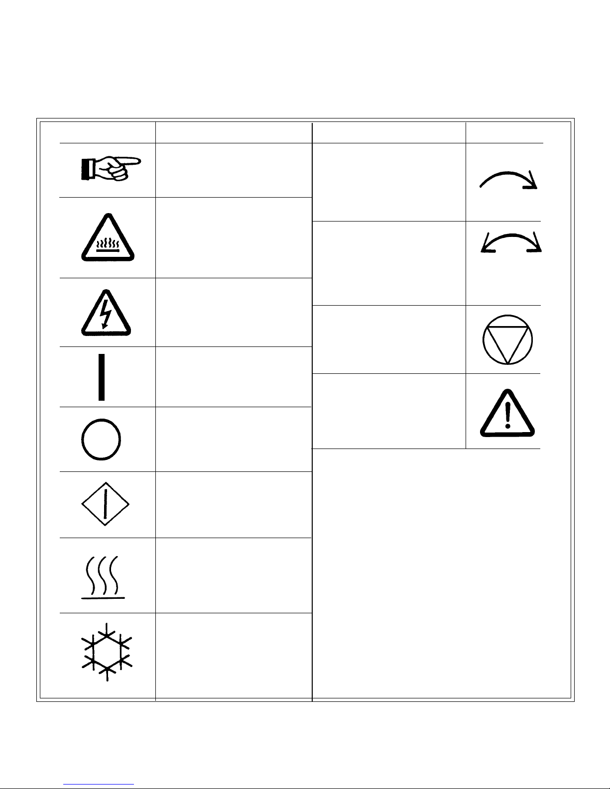
SYMBOLS
The following symbols are used in this manual and/or on the machine. The numbers between ()
refer to the numbers on the machine surveys.
DescriptionSymbol
NOTE!
Hot! Do Not Touch
Heiß! Nicht Beruhren
Haute temperature! Ne pas
toucher
Caliente! no tocar
dangerous voltage
tension dangereuse
Gefährliche elektrische
Spannung
tension peligrosa
On
Marche
Ein
Conectado
Off
Arrêt
Aus
Desconectado
Symbol
Rotation in two directions
Rotation dans les deux sens
Drehbewigung in zwei
Richtungen
Movimiento rotativo en los
dos sentidos
Direction of rotation
Sens de mouvement continu
De rotation Drehbewegung
in Pfeilrichtung movimiento
Giratorio o rotatorio en el
sentido de la flecha
End of Cycle
Caution
Attention
Achtung
Atencion; precaucion
Start
Demarrage
Start
Arranque de un
movimiento
Emission of heat in general
Emission de chaleur en
general
Warmeabgabe allgemein
Emisión de calor
Cooling
Refroidissement
Kühlen
Enfriamiento
Page 7

Unpacking/General Installation (All Dryers)
UNPACKING
GENERAL
INSTALLATION
(ALL DRYERS)
Upon arrival of the equipment, any damage in shipment
should be reported to the carrier immediately.
Upon locating permanent location of a unit, care should be
taken in movement and placement of equipment.
See outline clearance diagrams for correct dimensions.
Remove all packing material such as: tape, manuals, skid,
etc
Leveling: Use spirit level on top of dryer. Adjust leveling
bolts on dryer (see adjustable leveling bolts in maintenance
section).
Check voltage and amperes on rating plate before
installing the dryer.
The construction of the dryers permits installation side-byside to save space or to provide a wall arrangement.
Position dryer for the least amount of exhaust piping and
elbows, and allow free access to the rear of dryer for future
servicing of belts, pulleys and motors. Installation
clearance from all combustable material is 0 ceiling
clearance, 0 rear clearance, and 0 side clearance.
Before operating dryer, open basket door and remove
blocking between front panel and basket. Read the
instruction tags, owners manual, warnings, etc.
IMPORTANT
Opening the clothes loading door deactivates the
door switch to shut off the motors, fan, gas, steam,
or electric element. To restart the dryer, close
the door and press in the push to start button.
IMPORTANT
This dryer is designed for a capacity maximum
load. Overloading it will result in long drying
times and damp spots on some clothes.
IMPORTANT
Maximum operating efficiency is dependent upon
proper air curculation. The lint screen must be
kept cleaned daily to insure proper air circulation
throughout the dryer.
IMPORTANT
Provide adequate clearance for air opening into
the combustion chamber.
Page 8
Unpacking/General Installation (All Dryers)
GENERAL
INFORMATION
DRYER
COOL-DOWN
CYCLE
The dryer is so designed that when an operator opens the
dryer door, the basket and exhaust fan stop. You can
expect fast drying from a laundry dryer. Hot, dry air is
properly and effectively moved through the basket and
exhausted through a lint trap to the atmosphere. The
dryer comes equipped with an inclined self-cleaning lint
screen. In this system, lint accumulates on the underside
of the screen until a blanket of lint will fall from the
screen to the bottom of the dryer cabinet, and should be
removed daily or as required, to prevent an overaccumulation.
IMPORTANT
Provide adequate clearance for air openings into
the combustion chamber.
Permanent press, durable press and other modern day
fabrics require the care that your laundry dryers now
provide. At the end of the drying cycle, a timed CoolDown control automatically takes over and continues the
rotation of the fan and basket without heat until the
garment load reaches a safe cool temperature. This
function is performed at the end of each drying cycle and
continues for two minutes.
REPLACEMENT
PARTS
Replacement parts for this dryer are available from your
distributor or by contracting the factory at the address or
phone number printed on the cover page of this manual.
Page 9
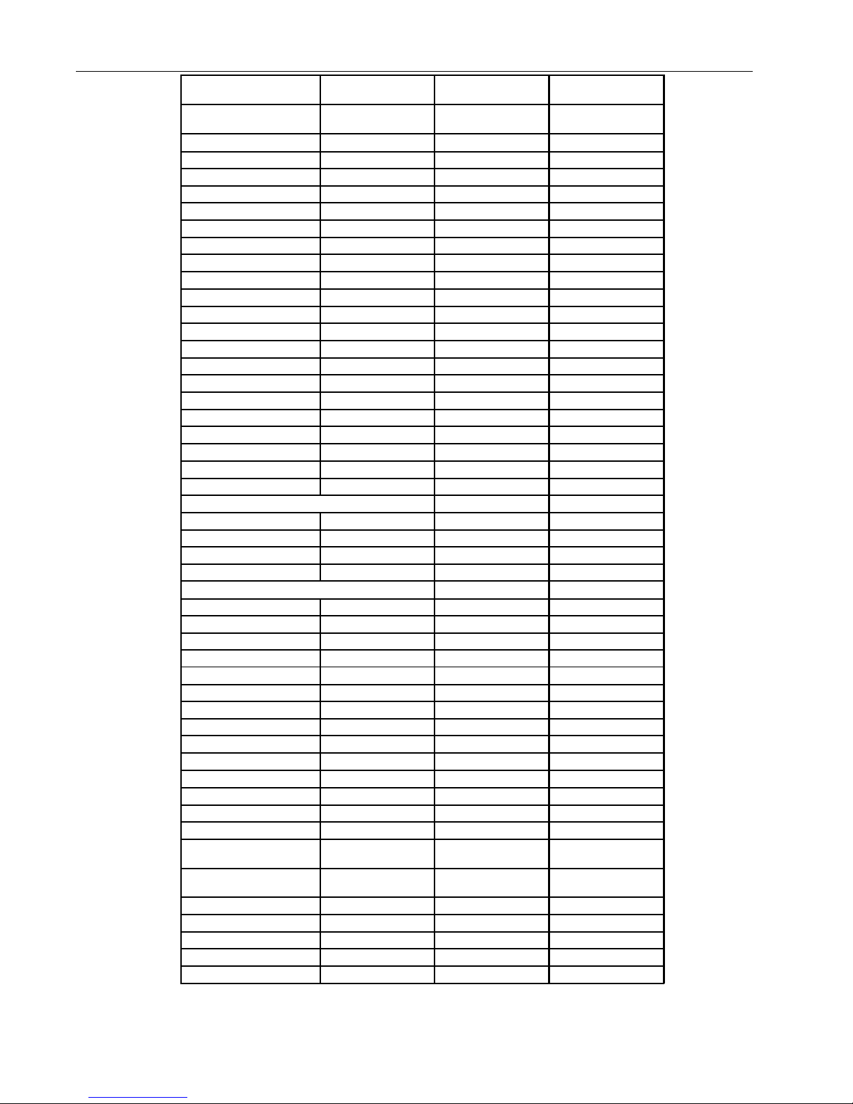
HD75.1 lb. Dryer Dimensions - Standard Gas
S pe c ific a tio ns U .S . M e a su re
Capacity
(D ry L ine n)
75 lbs. 34 kg
Metric
Measure
Basket
Diameter 37 inches 940 mm
Depth 36 inches 914 mm
Vo lu m e 2 2 .4 ft
3
634 liters
Cabinet
Height 78-1/4 inches 1988 mm
Width 39 inches 990 mm
Depth 52 inches 1321 mm
Door Opening
Diameter 22-5/8 inches 575 mm
Lo ading height 35 -1/2 inches 902 mm
Te m pe rature
M inim um 1 00
Maximum 185
0
F38
0
F85
o
C
0
C
Motor
Non-reversing 3/4 H P 0.56 kW
Reversing - Drum 1/2 HP 0.37 kW
Fan 1/3 H P 0.25 kW
E xhaust
3
Flow Rate 1000 cfm 1700 m
/h
Diameter 8 inches 203 mm
E le ctric C onn. - E le ctric D rye rs
N on-R ev ersing Rev ersing
208 V 60 - 3 PH 89 A 88 A
220/240 V 50/60 - 3 PH 72/78 A 72/78 A
380/415 V 50 - 3 PH 44/48 A 43/46 A
480 V 60 - 3 PH 38 A 39 A
Ele ctric Co nn. - Ste am, G as D rye rs
N on-R e versing R eve rsing
120/208-240 V 50/60 - 1 PH 10.06/5.4 A N/A
208/240 V 50/60 - 3 PH 4.2/4.1 A 5.5/5.4 A
480 V 60 - 3 PH 1.6 A 2.5 A
380/415 V 50 - 3 PH 1.7/1.8 A 4.3/4.4 A
Power
Electric 30 kW 30kW
Gas 189,000 Btu/h 47,627 kcal/h
Steam 5.9 BH P 49,842 kcal/h
Steam connection
Inlet 3 /4 " D N 2 0
Outlet 1/2" D N15
G as C onne ctio n
Gas Connection 1/2" DN15
Gas Pressure 6" - 12" 15-30 mb
Shipping
D im ensions
(H xW x D)
87 X 42 X 57
inches
2210 X 1067
X 1448 mm
Weight
Gas/Elec.N et 827 lbs. 375 kg
Gas/Elec. G ross 860 lbs. 390 kg
Steam N et 865 lbs. 392 kg
Steam G ross 900 lbs. 408 kg
Page 10
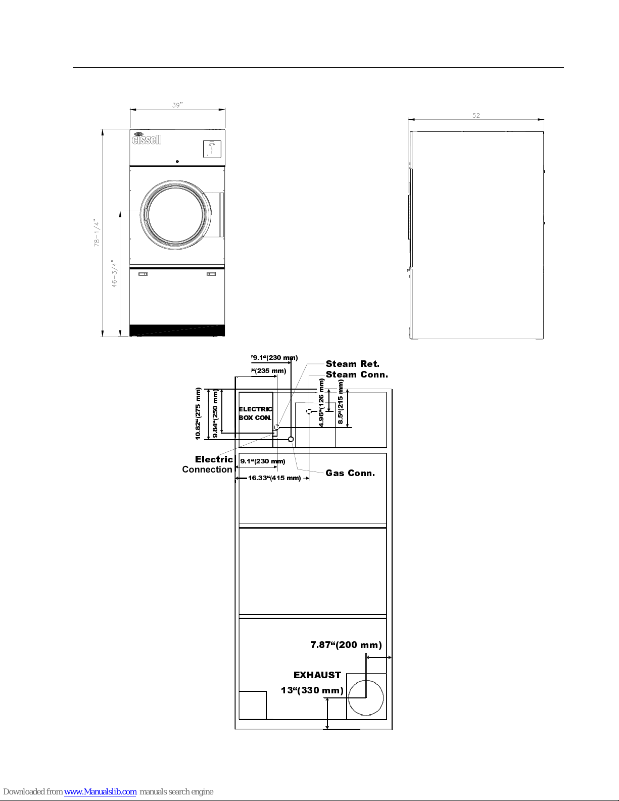
HD75.1 Dryer Dimensions - Gas, Steam and Electric
´
(Illustration)
P
P
P
P
´
´
(OHFWULF
Connection
,QOHW
´PP
(/(&75,&
%2;&21
´PP
´PP
PP
´PP
6WHDP5HW
6WHDP&RQQ
P
P
P
P
´
´
*DV&RQQ
(;+$867
´PP
Page 11
Electric connection
Dryers must be electrically grounded by a separate #14 or larger green wire from the grounding terminal
within the Service Connection Box, to a cold water pipe. In all cases, the grounding method must comply
with local electrical code requirements; or in the absence of local codes, with the National Electrical Code,
ANSI/NFPA 70 or the Canadian Electrical Code, CA C22.1.
See wiring diagram furnished with dryer. Do not change wiring without consulting the factory, as you may
void the factory warranty. DO NOT CONNECT THE DRYER TO ANY VOLTAGE OR CURRENT OTHER
THAN THAT SPECIFIED ON THE DRYER RATING PLATE. (Wiring diagram is located on rear wall of dryer.)
All panels must be in position before operation of dryer.
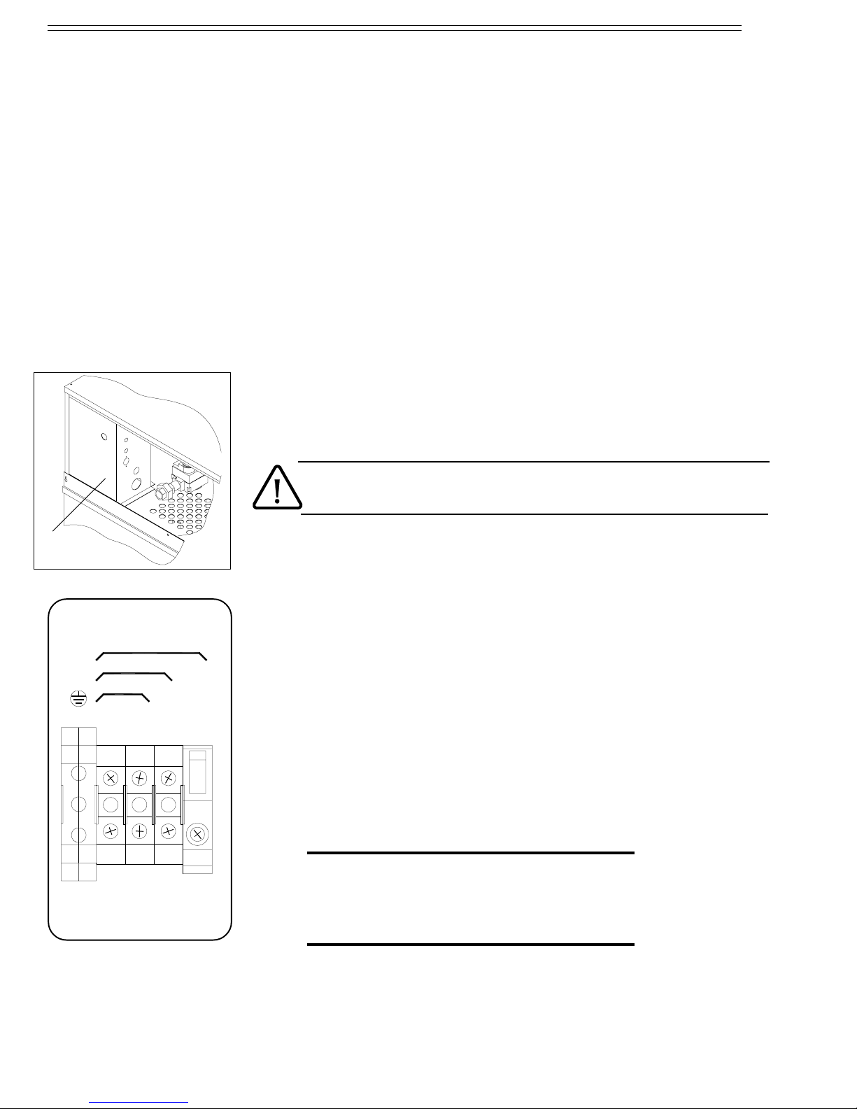
The connection needs to be made in the wiring box at the back. Open the coverplate
(G) in order to reach the connection clamps.
The connection cable needs to be brought in through the opening on the side of the
wiring box.
It is necessary to ground the dryer for your personal safety and to ensure a good
operation.
G
3 X 380-415 + N
3 X 208-240V
208-240V
115 and 208-240 V - 1 ph
The mains wires (Ll) and (L2) should be connected to the 2 left blocks and the
yellow/green grounding wire (PE) should be connected to the grounding block.
208-240 and 480 V - 3 ph
The 3 mains wires (L1), (L2) and (L3) should be connected to the 3 left blocks and
the yellow/green grounding wire (PE) should be connected to the grounding
block.
PE
L1 L2 L3 N
380-415V - 3 ph
The 3 mains wires (L1), (L2) and (L3) should be connected to the 3 left blocks,
the blue neutral (N) should be connected to the right block and the yellow/green
grounding wire (PE) should be connected to the grounding block.
«Attention. Lors des opérations dentretien
des commandes, ètiqueter tous les fils avant
de les dèconnecter. Toute erreur de câblage
peut être une source de danger et de panne»
Page 12
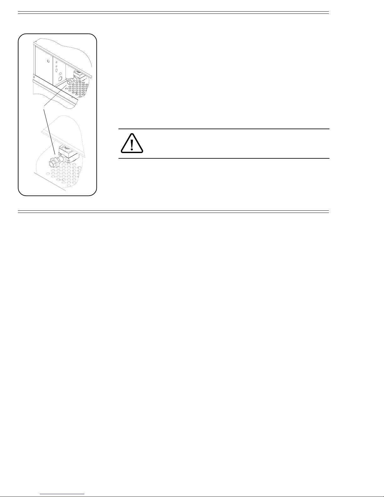
Gas connection
The gas supply pipe should be connected to the union (I), which is on the right next
to the wiring box on the back.
It is very important to have the connections done by a qualified technician, in order
to make sure that the installation is effected in accordance with the prevailing
standards and instructions.
The dryer should be connected to the type of gas, which is indicated on the serial plate.
The use of too small gas pipes can result in unsufficient gas supply, which can lead
to a bad heating-up and a poor drying quality.
I
When the dryer is used in combination with a weighing platform, the gas supply
pipe has to be made of flexible material to allow the weighing system to keep
moving freely.
Test all connections for possible leaks by means of a soap solution, but
never with a flame.
It is important to work with the right gas pressure (see technical remarks) in order to
obtain a good ignition, heating and consequently a good operation in general.
After the gas supply has been connected, the gas tap in the dryer should beturned on
(clockwise).
Page 13

Gas Piping Installation
GAS PIPING
INSTALLATION
1. The installation must conform with local codes, or in
the absence of local codes with the National Fuel
Gas Code, ANSI Z223.1 or the CAN/CGA-B149,
Installation Codes.
2. Check Identification Nameplate for type of gas for
dryer.
3. Check for altitude elevation of dryer.
4. Check with utilities company for proper gas
pressure and gas supply line.
5. Natural Gas OnlyCheck the gas pressure inlet
supply to dryer, 11 inches water column (27.4 mbar)
maximum. Manifold Pressure3.5 inches water
column (8.8 mbar) pressure.
6. L.P. Gas OnlyCheck the gas pressure inlet supply
to dryer, 13 inches water column (32.4 mbar)
maximum. Manifold Pressure11 inches water
column (27.4 mbar) pressure.
CAUTION: Low gas pressure and intermittent gas will
cause gas ignition problems and inadequate drying of
laundry.
Page 14
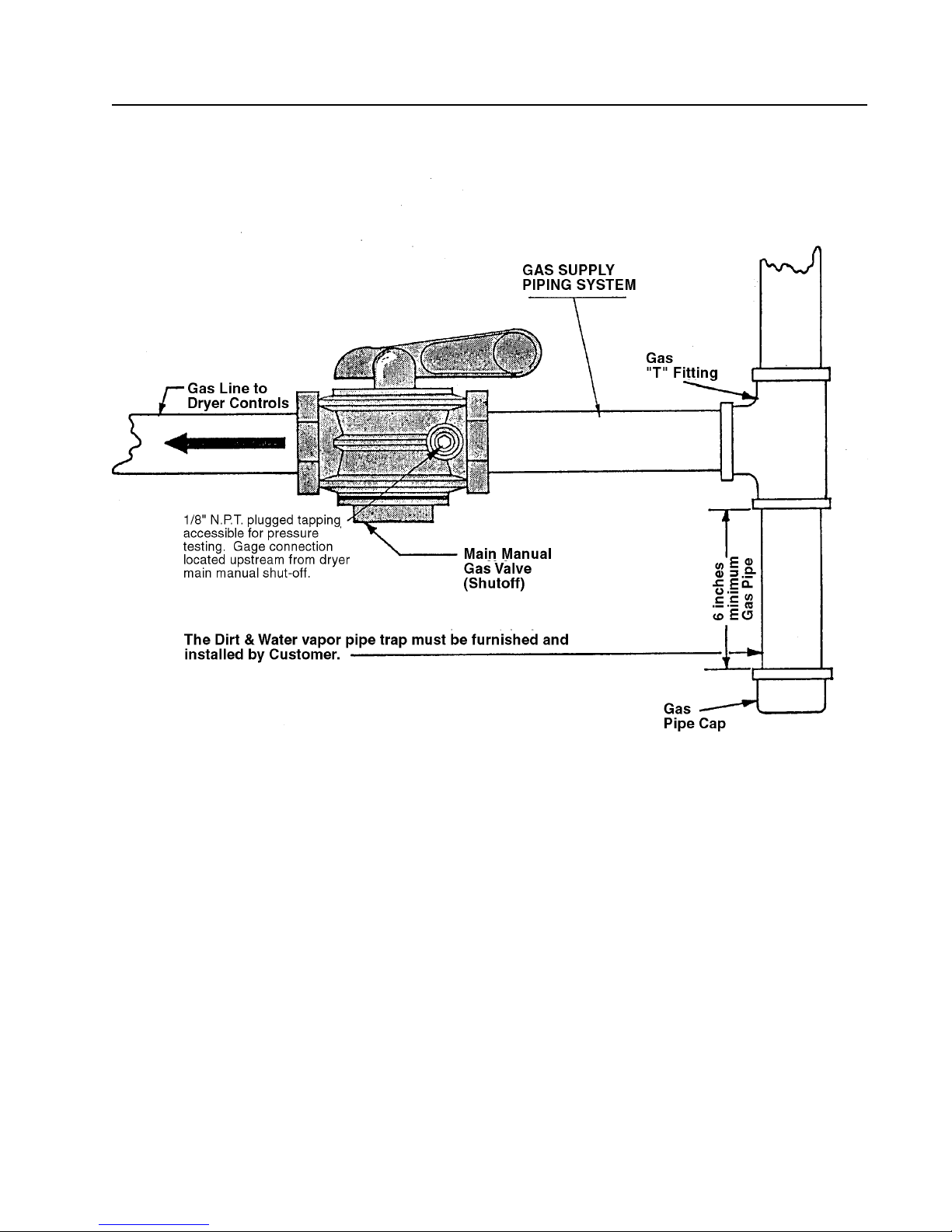
Gas Piping Installation (Illustrations)
The dryer and its individual shutoff valve must be disconnected from the gas supply
piping system during any pressure testing of that system at test pressures in excess of
1/2 psig (.04 bar).
The dryer must be isolated from the gas supply piping system by closing it's
individual manual shutoff valve during any pressure testing of the gas supply piping
system at test pressures equal to or less than 1/2 psig (.04 bar).
Page 15
Gas Service Installation Instructions
GAS SERVICE
INSTALLATION
INSTRUCTIONS
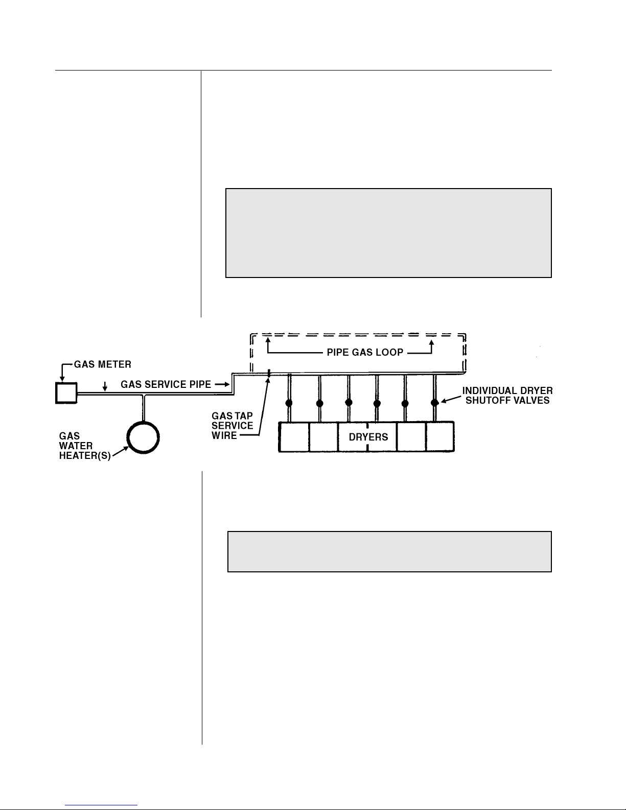
The size of the gas service pipe is dependant upon many
variables, such as tees, lengths, etc. Specific pipe size
should be obtained from the gas supplier. Refer to the Gas
Pipe Size chart in this manual for general gas pipe size
information.
CAUTION: Gas loop piping must be installed as
illustrated to maintain equal gas pressure for all
dryers connected to a single gas service
Other gas-using appliances should be connected
upstream from the loop.
GAS PRESSURE
REGULATOR FOR
LIQUIFIED
PETROLEUM GASES
WARNING:
LIQUIFIED PETROLEUM GASES ONLY !
A Gas Pressure Regulator for Liquified Petroleum Gases is
not furnished on Gas Heated Clothes Dryers. This
regulator is normally furnished by the installer. In
accordance with American Gas Association (AGA)
standards, a gas pressure regulator, when installed
indoors, must be equipped with a vent limiter or a vent
line must be installed from the gas pressure regulator vent
to the outdoors.
Page 16
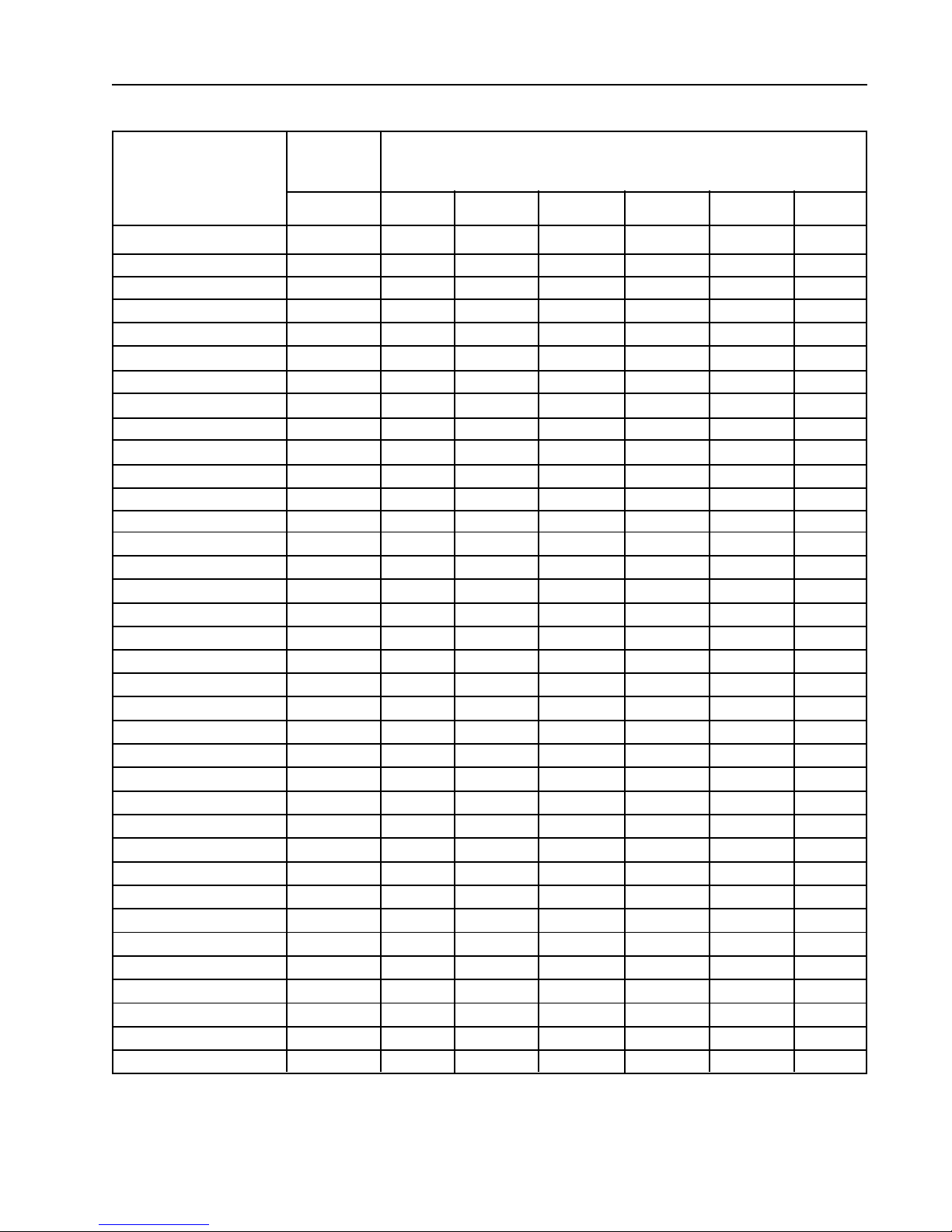
Gas Pipe Size Chart
TOTAL BTU/HR
(for LP Gas correct
total BTU/HR below by
multiplying by .6)
60,000
80,000
100,000
120,000
140,000
160,000
180,000
200,000
300,000
400,000
500,000
600,000
700,000
800,000
900,000
1,000,000
1,100,000
1,200,000
1,300,000
1,400,000
1,500,000
1,600,000
1,700,000
1,800,000
1,900,000
2,000,000
2,200,000
2,400,000
2,600,000
2,800,000
3,000,000
3,200,000
3,400,000
3,600,000
3,800,000
4,000,000
TOTAL
KCAL
HOUR
15000
20000
25200
30200
35200
40300
45300
50400
75600
100800
126000
151200
176400
202000
230000
250000
270000
300000
330000
350000
380000
400000
430000
450000
480000
504000
550000
605000
650000
705000
750000
806000
850000
907000
960000
1000000
GAS PIPE SIZE FOR 1000 BTU (250 KCAL) NATURAL GAS
In figuring total length of pipe, make allowance for tees and elbows.
(25 ft.)
7,62 m
3/4
3/4
3/4
3/4
3/4
3/4
1
1
1
1 1/4
1 1/4
1 1/2
1 1/2
1 1/2
2
2
2
2
2
2
2
2
2
2 1/2
2 1/2
2 1/2
2 1/2
2 1/2
2 1/2
2 1/2
2 1/2
3
3
3
3
3
AT 7 (17.5 MBAR) W.C. PRESSURE
(50 ft.)
15,24 m
3/4
3/4
3/4
1
1
1
1
1
1 1/4
1 1/4
1 1/2
1 1/2
2
2
2
2
2
2
2 1/2
2 1/2
2 1/2
2 1/2
2 1/2
2 1/2
2 1/2
2 1/2
3
3
3
3
3
3
3 1/2
3 1/2
3 1/2
3 1/2
(75 ft.)
22,86 m
3/4
3/4
1
1
1
1
1
1 1/4
1 1/4
1 1/2
1 1/2
2
2
2
2
2
2 1/2
2 1/2
2 1/2
2 1/2
2 1/2
2 1/2
2 1/2
3
3
3
3
3
3
3
3 1/2
3 1/2
3 1/2
3 1/2
3 1/2
3 1/2
(100 ft.)
30,48 m
3/4
1
1
1
1
1 1/4
1 1/4
1 1/4
1 1/2
1 1/2
2
2
2
2
2 1/2
2 1/2
2 1/2
2 1/2
2 1/2
2 1/2
2 1/2
3
3
3
3
3
3
3
3 1/2
3 1/2
3 1/2
3 1/2
3 1/2
3 1/2
4
4
(125 ft.)
38,1 m
3/4
1
1
1
1
1 1/4
1 1/4
1 1/4
1 1/2
1 1/2
2
2
2
2 1/2
2 1/2
2 1/2
2 1/2
2 1/2
2 1/2
3
3
3
3
3
3
3
3 1/2
3 1/2
3 1/2
3 1/2
3 1/2
3 1/2
4
4
4
4
(150 ft.)
45,72 m
3/4
1
1
1
1 1/4
1 1/4
1 1/4
1 1/2
1 1/2
2
2
2
2 1/2
2 1/2
2 1/2
2 1/2
2 1/2
2 1/2
3
3
3
3
3
3
3
3 1/2
3 1/2
3 1/2
3 1/2
3 1/2
4
4
4
4
4
4
Page 17

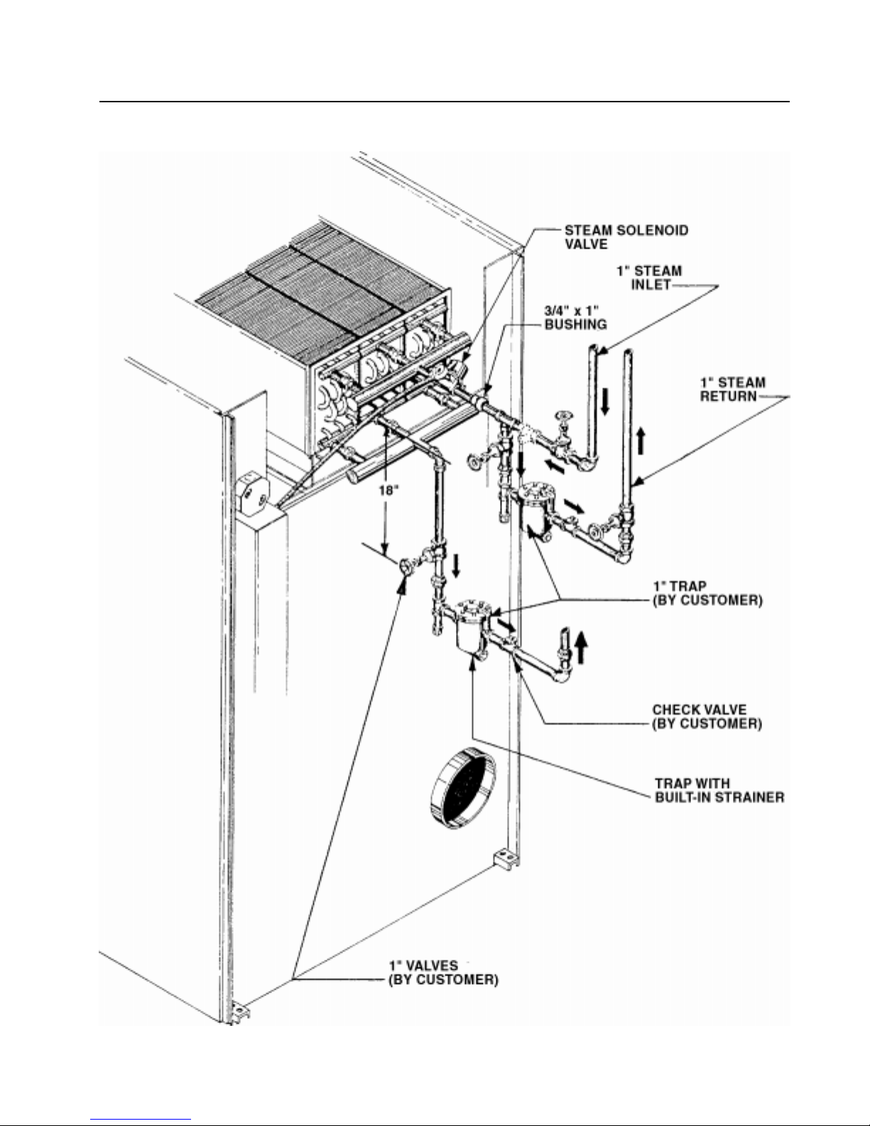
Steam Piping Installation Instructions
STEAM PIPING
INSTALLATION
INSTRUCTIONS
1. Set and anchor dryer in position. Machine should be level to
assure proper steam circulation.
2. To prevent condensate draining from headers to dryer, piping
should have a minimum 12" above respective header. Do not
make steam connection to header with a horizontal or
downwardly facing tee or elbow.
3. Whenever possible, horizontal runs of steam lines must drain,
by gravity, to respective steam header. Water pockets, or an
imporperly drained steam header will provide wet steam,
causing improper operation of dryer. If pockets or improper
drainage cannot be eliminated, install a by-pass trap to drain
condensate from the low point in the steam supply header to
the return.
4. In both steam supply and steam return line, it is recommended
that each have a 3/4" union and 3/4" globe valve. This will
enable you to disconnect the steam connections and service
the dryer while your plant is in operation.
5. Before connecting trap and check valve to dryer, open globe
valve in steam supply line and allow steam to flow through
dryer to flush out any dirt and scale from dryer. This will
assure proper operation of trap when connected.
6. After flushing system, install bucket trap (with built-in
strainer) and check valve. For successful operation of dryer,
install trap 18" below coil and as near to the dryer as
possible. Inspect trap carefully for inlet and outlet markings
and install according to trap manufacturer's instructions. If
steam is gravity returned to boiler, omit trap but install check
valve in return line near dryer.
7. Install union and globe valve in return line and make final
pipe connections to return header.
Page 18
Steam Piping Installation (Illustration)
Page 19
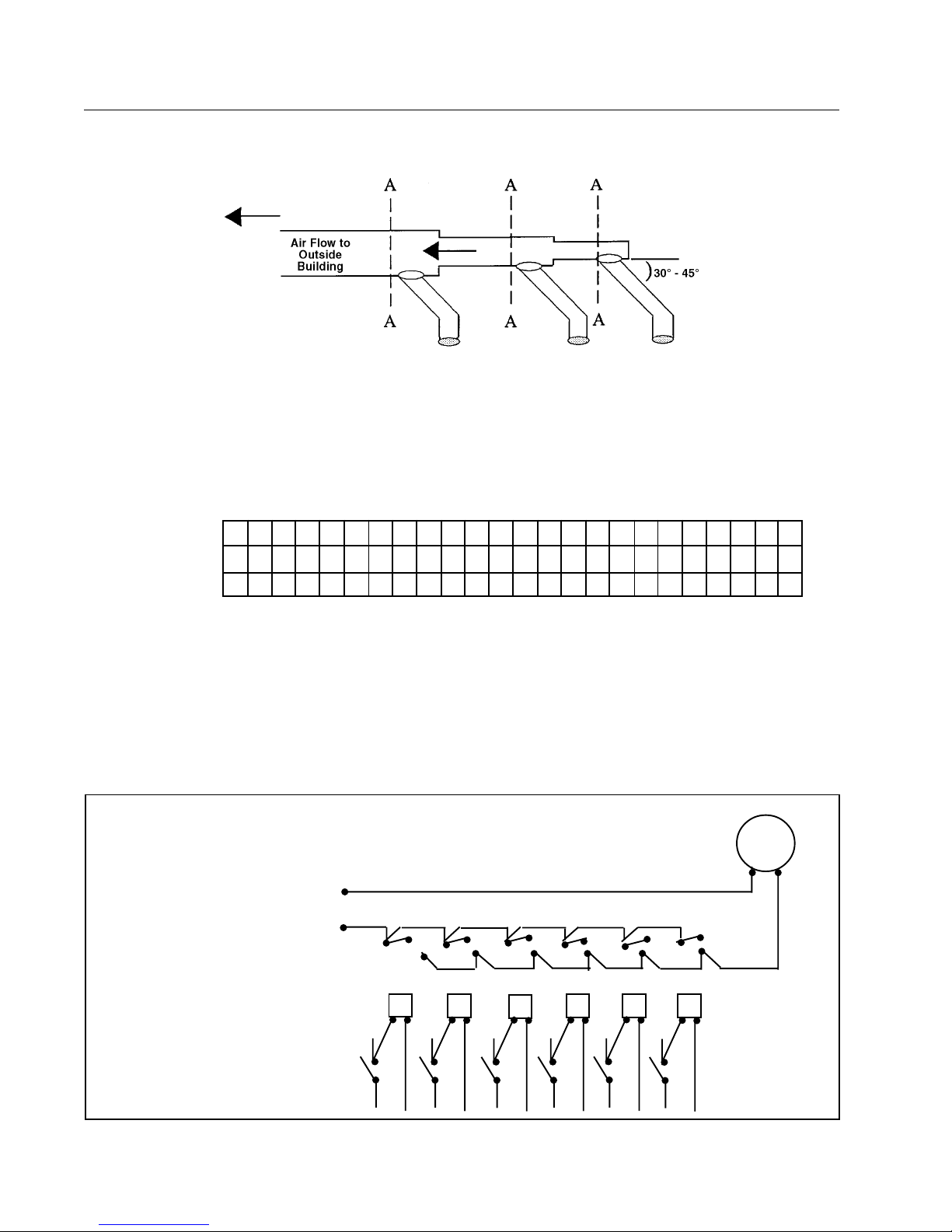
No. of Dryers
Duct Diameter
(in inches)
(in CM)
Dryer Installation With Multiple Exhaust
For Exhaust Duct less than 14 feet (5 m) and 2
elbows equivalent and less than 0.3 inches (8 mm)
static pressure.
DRYER EXHAUSTS
Area of section A-A must be equal to the sum of dryer exhaust pipes
entering multiple exhaust pipe. (See chart below.)
HD75
123456789101112131415161718192021222324
8 12141618202223242627282930313233343536 37383940
20 30 25 41 46 51 56 58 61 66 68 71 73 76 78 81 84 86 89 91 94 97 99 100
Power Supply
to Fan
Relay Coils
Start and Stop
Switches on
Dryers
_ _ _ _
Page 20
_ _ _ _
_ _ _ _
Exhaust
Booster Fan
_ _ _ _
_ _ _ _
_ _ _ _
 Loading...