

Cissell MANHD150, HD150.1 Owner's Manual
OWNER'S MANUAL
150 lb. HD LAUNDRY DRYER
Gas: Natural and LP
Steam
Technical specifications
Installation instructions
Operating instructions
Maintenance
HD150.1
THIS MANUAL MUST BE GIVEN TO THE EQUIPMENT OWNER
MANHD150 3/06
Cissell Manufacturing Co.
831 S. First St. - P.O.Box 32270 - Louisville, Ky. - 40232-2270
Tel: (502) 587-1292 - Fax: (502) 585-2333
Sales Fax: (502) 585-3625 - Service/Parts Fax: (502) 681-1275
Page 1
IMPORTANT NOTICES—PLEASE READ
For optimum efficiency and safety, we recommend that you read the Manual before operating the equipment. Store this manual in a file
or binder and keep for future reference.
WARNING: For your safety, the information in this manual must be followed
to minimize the risk of fire or explosion or to prevent property damage,
personal injury, or loss of life.
- Do not store or use gasoline or other flammable liquids or vapors in the
vicinity of this or any other appliance.
- WHAT TO DO IF YOU SMELL GAS
• Do not try to light any appliances.
• Do not touch any electrical switch; do not use any phone in your building.
• Clear the room, building, or area of all occupants.
• Immediately call your gas supplier from a neighbor's phone. Follow the
gas supplier's instructions.
• If you cannot reach the gas supplier, call the fire department.
Installation and service must be performed by a qualified installer, service
agency or the gas supplier.
WARNING: In the event the user smells gas odor, instructions on what to do must be
posted in a prominent location. This information can be obtained from the local gas
supplier.
WARNING: Wear Safety Shoes to prevent injuries.
WARNING: Purchaser must post the following notice in a prominent location:
FOR YOUR SAFETY
Do not store or use gasoline or other flammable vapors
and liquids in the vicinity of this or any other appliance.
WARNING: A clothes dryer produces combustible lint and should be exhausted outside the
building. The dryer and the area around the dryer should be kept free of lint.
WARNING: Be safe, before servicing machine, the main power should be shut off.
Page 2
IMPORTANT NOTICES—PLEASE READ
WARNING: To avoid fire hazard, do not dry articles containing foam rubber or similar texture
materials. Do not put into this dryer flammable items such as baby bed mattresses, throw rugs,
undergarments (brassieres, etc.) and other items which use rubber as padding or backing. Rubber easily
oxidizes causing excessive heat and possible fire. These items should be air dried.
WARNING: Synthetic solvent fumes from drycleaning machines create acids when drawn through the
dryer. These fumes cause rusting of painted parts, pitting of bright or plated parts, and completely
removes the zinc from galvanized parts, such as the tumbler basket. If drycleaning machines are in the
same area as the tumbler, the tumbler's make-up air must come from a source free of solvent fumes.
WARNING: Do not operate without guards in place.
WARNING: Check the lint trap often and clean as needed but at least a minimum of once per day.
WARNING: Alterations to equipment may not be carried out without consulting with the factory and
only by a qualified engineer or technician. Only Manufacturer’s parts may be used.
WARNING: Remove clothes from dryer as soon as it stops. This keeps wrinkles from setting in and
reduces the possibility of spontaneous combustion.
WARNING: Be Safe - shut main electrical power and gas supply off externally before attempting
service.
WARNING: Never use drycleaning solvents, gasoline, kerosene, or other flammable liquids in the dryer.
FIRE AND EXPLOSION WILL OCCUR. NEVER PUT FABRICS TREATED WITH THESE
LIQUIDS INTO THE DRYER. NEVER USE THESE LIQUIDS NEAR THE DRYER..
WARNING: Do not place items exposed to cooking oils in your dryer. Items contaminated
with cooking oils may contribute to a chemical reaction that could cause a load to catch fire.
WARNING: Never let children play near or operate the dryer. Serious injury could occur if a child
should crawl inside and the dryer is turned on.
WARNING: Never tumble fiberglass materials in the dryer unless the labels say they are machine
dryable. Glass fibers break and can remain in the dryer. These fibers cause skin irritation if they
become mixed with other fabrics.
WARNING: Before operating gas ignition system - purge air from natural gas or propane gas lines
per manufacturer’s instructions.
WARNING: To reduce the risk of electric shock, disconnect this appliance from the power supply
before attempting any user maintenance other than cleaning the lint trap. Turning the controls to the
OFF position does not disconnect this appliance from the power supply.
Page 3
IMPORTANT NOTICES—PLEASE READ
ATTENTION: L’ACHETEUR DOIT PLACER L’AVERTISSEMENT
SUIVANT DANS UN ENDROIT CLAIR ET VISIBLE:
AVERTISSEMENT. Assurez-vous de bien
suivre les instructions donnees dans cette
notice pour reduire au minimum le risque
d’incendie ou d’explosion ou pour eviter tuot
dommage materiel, toute blessure ou la mort.
__ Ne pas entreposer ni utiliser d’essence ni
d’autres vapeurs ou liquides inflammables dans
le voisinage de cet appareil ou de tout autre
apparell.
__ QUE FAIRE SI VOUS SENTEZ UNE
ODEUR DE GAZ:
• Ne pas tenter d’allumer d’apparell.
• Ne touchez a aucun interrupteur. Ne pas
vous servir des telephones se trouvant dans
le batiment ou vous vous trouvez.
• Evacuez la piece, le batiment ou la zone.
• Appelez immediatement votre fournisseur de
gaz depuis un voisin. Suivez les instructions
du fournisseur.
• Si vous ne pouvez rejoindre le fournisseur
de gaz, appelez le service des incendies.
__ l’installation et l’entretien doivent etre assures
par un installateur ou un service d’entretien
qualifie ou par le fournisseur de gaz.
ATTENTION: L’ACHETEUR DOIT PLACER L’AVERTISSEMENT
SUIVANT DANS UN ENDROIT CLAIR ET VISIBLE:
POUR VOTRE SECURITE
Ne pas entreposer ni utiliser d’ essence
ni d’autres vapeurs ou liquides
inflammables dans le voisinage de cet
appareil ou de tout autre appareil.
Page 4

CISSELL WARRANTY
The Cissell Manufacturing Company (Cissell) warrants all new equipment (and the original parts thereof) to be free from defects
in material or workmanship for a period of three (3) years from the date of sale thereof to an original purchaser for use, except
as hereinafter provided. With respect to non-durable parts normally requiring replacement in less than three (3) years due to
normal wear and tear, and with respect to all new repair or replacement parts for Cissell equipment for which the three (3) year
warranty period has expired, or for all new repair or replacement parts for equipment other than Cissell equipment, the warranty
period is limited to ninety (90) days from date of sale. The warranty period on each new replacement part furnished by Cissell
in fulfillment of the warranty on new equipment or parts shall be for the unexpired portion of the original warranty period on
the part replaced.
With respect to electric motors, coin meters and other accessories furnished with the new equipment, but
not manufactured by Cissell, the warranty is limited to that provided by the respective manufacturer.
Cissell's total liability arising out of the manufacture and sale of new equipment and parts, whether under
the warranty or caused by Cissell's negligence or otherwise, shall be limited to Cissell repairing or replacing,
at its option, any defective equipment or part returned f.o.b. Cissell's factory, transportation prepaid, within
the applicable warranty period and found by Cissell to have been defective, and in no event shall Cissell be
liable for damages of any kind, whether for any injury to persons or property or for any special or
consequential damages. The liability of Cissell does not include furnishing (or paying for) any labor such
as that required to service, remove or install; to diagnose troubles; to adjust, remove or replace defective
equipment or a part; nor does it include any responsibility for transportation expense which is involved
therein.
The warranty of Cissell is contingent upon installation and use of its equipment under normal operating
conditions. The warranty is void on equipment or parts; that have been subjected to misuse, accident, or
negligent damage; operated under loads, pressures, speeds, electrical connections, plumbing, or conditions
other than those specified by Cissell; operated or repaired with other than genuine Cissell replacement
parts; damaged by fire, flood, vandalism, or such other causes beyond the control of Cissell; altered or
repaired in any way that effects the reliability or detracts from its performance, or; which have had the
identification plate, or serial number, altered, defaced, or removed.
No defective equipment or part may be returned to Cissell for repair or replacement without prior written
authorization from Cissell. Charges for unauthorized repairs will not be accepted or paid by Cissell.
CISSELL MAKES NO OTHER EXPRESS OR IMPLIED WARRANTY, STATUTORY OR OTHERWISE,
CONCERNING THE EQUIPMENT OR PARTS INCLUDING, WITHOUT LIMITATION, A WARRANTY
OF FITNESS FOR A PARTICULAR PURPOSE, OR A WARRANTY OF MERCHANTABILITY. THE
WARRANTIES GIVEN ABOVE ARE EXPRESSLY IN LIEU OF ALL OTHER WARRANTIES, EXPRESS
OR IMPLIED. CISSELL NEITHER ASSUMES, NOR AUTHORIZES ANY PERSON TO ASSUME FOR IT,
ANY OTHER WARRANTY OR LIABILITY IN CONNECTION WITH THE MANUFACTURE, USE OR SALE
OF ITS EQUIPMENT OR PARTS.
For warranty service, contact the Distributor from whom the Cissell equipment or part was purchased. If
the Distributor cannot be reached, contact Cissell.
IDENTIFICATION NAMEPLATE
The Identification Nameplate is located on the rear wall of the dryer. It contains the dryer serial number, product
number, model number, electrical specifications and other important data that may be needed when servicing
and ordering parts, wiring diagrams, etc. Do not remove this nameplate.
Page 5

TABLE OF CONTENTS
PAGE
Model Numbers & Company Address.................................................................................. 1
Important Notices..............................................................................................................2-4
Dryer Warranty .................................................................................................................... 5
Table of Contents ..............................................................................................................6-7
Warnings, Symbols...........................................................................................................8-9
Unpacking/General Installation .......................................................................................10-11
General Dimensions .......................................................................................................12-13
Dryer Specifications.......................................................................................................14-15
Electrical Connections......................................................................................................... 16
Gas Piping .....................................................................................................................17-18
Gas Pipe Size Chart............................................................................................................ 19
Gas Piping Installation ......................................................................................................... 20
Bonnet Shipped Separately - Installation Instructions ......................................................21-22
Steam Piping Installation ................................................................................................23-24
Exhaust Installation - Multiple Exhaust ............................................................................25-27
Dryer Make-up Air Requirements ....................................................................................... 28
Exhaust Installation - Separate Exhaust................................................................................ 29
Dryer Air Flow Installation .................................................................................................. 30
Rules for Safe Operation of Dryer....................................................................................... 31
Energy Saving Tips ............................................................................................................. 32
Operating Instructions -Two Timer Models ....................................................................33-35
Service Savers.................................................................................................................... 36
Troubleshooting Charts ..................................................................................................37-39
Direct-Spark Ignition Operation.....................................................................................40-41
General Maintenance .......................................................................................................... 42
Burner Air Inlet Adjustment ................................................................................................ 43
Basket Alignment (TM200 Gear Reducer) .....................................................................44-45
Basket Alignment (Gear Motor).......................................................................................... 46
Shimming the Basket and Spider Assembly ......................................................................... 47
Air Switch Adjustment........................................................................................................ 48
Dryers with Reversing Control Timer..............................................................................49-50
Large Gear Reducer Maintenance ....................................................................................... 51
Front Exploded View ......................................................................................................... 52
Rear View (TM200 Gear Reducer) ...............................................................................53-54
Rear View (Gear Motor) ...............................................................................................55-56
Front Panel and Door Assembly ......................................................................................... 57
Two Timer Thermostat Assembly........................................................................................ 58
Burner Access Door........................................................................................................... 59
Lint Door Assembly............................................................................................................ 60
DMP Sensor Assembly ...................................................................................................... 61
Two Timer Sensor Assembly .............................................................................................. 62
Pro Sensor Assembly ......................................................................................................... 63
ProHc Sensor Assembly..................................................................................................... 64
Page 6

TABLE OF CONTENTS
Air Switch Assembly .......................................................................................................... 65
Two Timer Control Panel Assembly.................................................................................... 66
DMP Control Panel Assembly ............................................................................................ 67
Pro Control Panel Assembly ............................................................................................... 68
ProHC Control Panel Assembly.......................................................................................... 69
Rear Motor Control Assembly............................................................................................ 70
Parts - TM200 Gear Reducer............................................................................................. 71
Gas Bonnet Assembly......................................................................................................... 72
Steam Bonnet Assembly - TU14027................................................................................... 73
Page 7
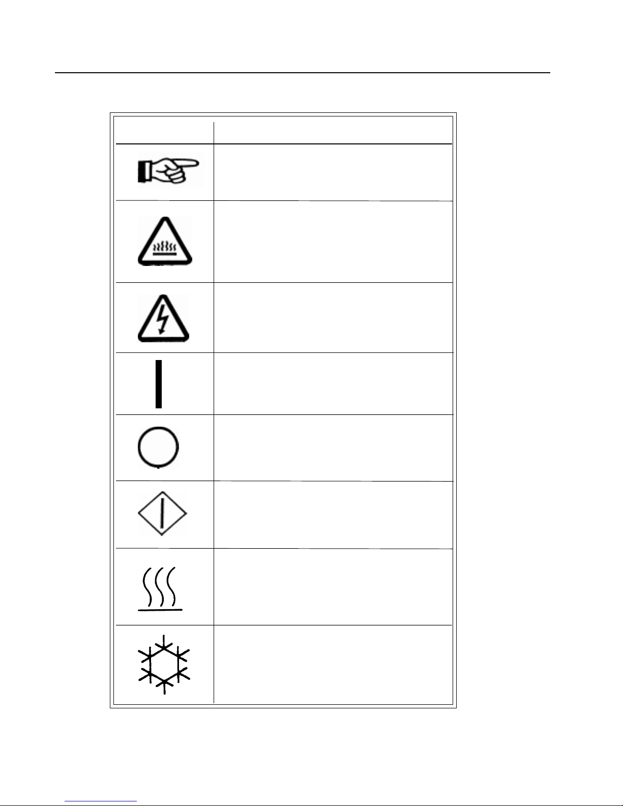
SYMBOLS
The following symbols are used in this manual and/or on the machine.
Symbol Description
NOTE!
Hot! Do Not Touch
Heiß! Nicht Beruhren
Haute temperature! Ne pas
toucher
Caliente! no tocar
dangerous voltage
tension dangereuse
Gefährliche elektrische
Spannung
tension peligrosa
on
marche
Ein
conectado
off
arrêt
Aus
desconectado
start
demarrage
Start
arranque de un movimiento
emission of heat in general
êmission de chaleur en
general
Warmeabgabe allgemein
emisión de calor
cooling
refroidissement
Kühlen
enfriamiento
Page 8
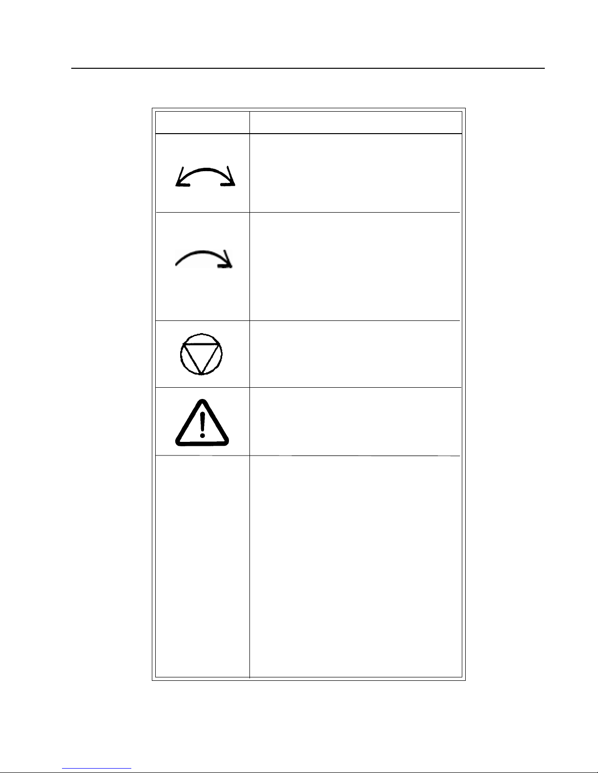
SYMBOLS
Symbol
Description
rotation in two directions
rotation dans les deux sens
Drehbewigung in zwei Richtungen
movimiento rotativo en los dos
sentidos
direction of rotation
sens de mouvement continu de rotation
Drehbewegung in Pfeilrichtung
movimiento giratorio o rotatorio
en el sentido de la flecha
End of Cycle
caution
attention
Achtung
atencion; precaucion
Page 9

UNPACKING/GENERAL INSTALLATION (ALL DRYERS)
UNPACKING
GENERAL
INSTALLATION
(ALL DRYERS)
This dryer is packed in a large wooden crate.
Upon arrival of the equipment, any damage in shipment should
be reported to the carrier immediately.
Upon locating permanent location of a unit, care should be taken
in movement and placement of equipment.
See outline clearance diagrams for correct dimensions.
Remove all packing material such as: tape, manuals, skid, etc.
Leveling: Use spirit level on top of dryer. The use of shims are acceptable
for this procedure.
Check voltage and amperes on rating plate before installing the
dryer.
The construction of the dryers permits installation side-by-side
to save space or to provide a wall arrangement. Position dryer
for the least amount of exhaust piping and elbows, and allow
free access to the rear of dryer for future servicing of belts,
pulleys and motors. Installation clearance from all combustable
material is 0” ceiling clearance, 0” rear clearance, and 0” side
clearance.
IMPORTANT
Opening the clothes loading door deactivates the
door switch to shut off the motors, fan, gas, steam, or
electric element. To restart the dryer, close the door
and press in the push to start button and hold briefly.
IMPORTANT
This dryer is designed for a capacity maximum load.
Overloading it will result in long drying times and
damp spots on some clothes.
IMPORTANT
Maximum operating efficiency is dependent upon
proper air curculation. The lint screen must be kept
cleaned daily to insure proper air circulation
throughout the dryer.
Page 10

GENERAL INSTALLATION (ALL DRYERS)
IMPORTANT
Provide adequate clearance for air openings into the
combustion chamber.
GENERAL
IMPORTANT
REPLACEMENT PARTS
PROCEDURE FOR
DISASSEMBLING THE
TOP OF THE DRYER
Replacement parts for this dryer are available from your distributor
or by contacting the factory at the address or phone number printed
on the cover of this manual.
1. Unscrew two (2) front cover panel hold-down screws and
open the front cover panel. If wires enclosed are not color
coded or numbered, mark wires before disconnecting. Refer
to the wiring diagram.
2. Disconnect the wire plugs in the right and left control boxes.
Unscrew the two (2) hold-down bolts from the bottom of the
boxes and one screw from the outside rear of the boxes.
Remove the two (2) screws that hold the conduit plate to the
boxes. Remove the boxes and the top brace as one assembly.
3. Unscrew the six (6) bolts that hold down the heating unit.
4. Remove the air switch box on the rear of the dryer and
disconnect the two (2) wires and the box from the rear of
the dryer. Leave the air switch fastened to the dryer rear
wall.
5. To re-assemble, reverse this procedure.
Page 11
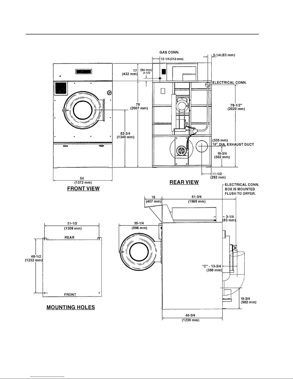
GAS DRYER DIMENSIONS
Page 12
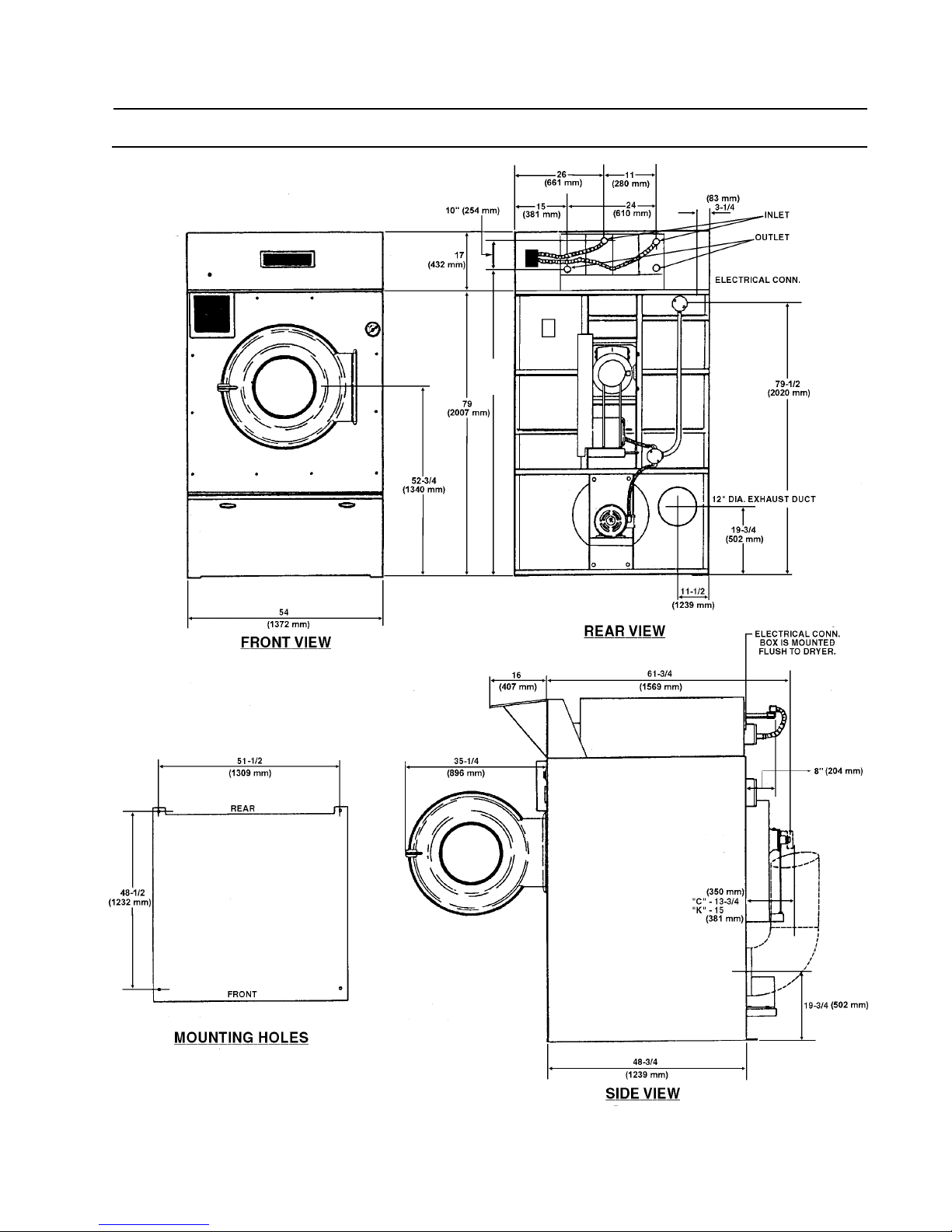
STEAM DRYER DIMENSIONS
Page 13

DRYER SPECIFICATIONS
GENERAL Floor Space ............................................64” (1626 mm) Deep x 54”
SPECIFICATIONS (1372 mm) Wide x 96”
FOR 150 lb. DRYERS (2439 mm) High
Doors .................................................... 31-1/4” (794 mm) Diameter
Basket Size..........................................50” (1270 mm) Diameter x
42” (1067 mm) Deep
Basket Capacity (Dry Weight) ........ 150 lbs. (68.0 kg) Dryweight
Basket Motor ...................................... 1-1/2 HP (1.12 kW)
Fan Motor ............................................ 1-1/2 HP (1.12 kW)
Basket RPM (Reversing) ................. 28 - 3.2 reversals per min.
(Non-Reversing) ................................. 3 0
Exhaust Duct .....................................12” (305 mm) Diameter
Maximum Air Displacement ...........2,250 cfm (3825 m3/h)
Recommended Operating................1,900 - 2,100 cfm
Range (3230 - 3570 m3/h)
Net Weight (Gas) ...............................1,740 lbs. (789 kg) approx.
(Steam)................................................. 1,754 lbs. (796 kg) approx.
Shipping Weight (Gas) .....................1,890 lbs. (857 kg) approx.
(Steam)................................................. 1,944 lbs. (882 kg) approx.
Export Shipping Dimensions.......... 104” H (2642 mm) x 60” W
(1524 mm) x 74” L (1880 mm)
Export Crate (Gas) ............................ 254.5 ft³ (7.21 m³)
(Steam)................................................. 261.1 ft³ (7.40 m³)
Load Weight on Floor Area ..............69 lb./sq. in. (48.5 lb./sq. in.)
BTU Input Rating * (see next page) ............... 370,000 Btu per hour
(93,240 kcal/h)
(Nat., Mixed, Mfg., Butane and
Propane Gases)
Steam Consumption .........................12.5 bhp - 419 lbs.
(418,187 Btu/h)
Operating Steam Pressure..............100 psi (6.9 bar) max
Gas Supply .......................................... 1” (3 mm) Pipe Connection
Manifold Pressure.............................3.5”w.c. (8.7 mbar) (Natural Gas)
11”w.c. (27 mbar) (LP Gas)
Electric Ignition ................................. Direct Spark Ignition System
Page 14

DRYER SPECIFICATIONS
STEAM HEA TED DRYERS ONL Y
Operating Steam Pressure 100 psig (6.9 bar) Maximum
Boiler HP 12.5 HP (9.33 kW)
Heat Capacity 8 Coil
Steam Coils (4) 6”(153 mm) x 10 1/4” (261 mm)
x 40 1/2”(1029 mm)
Steam Supply Connection 3/4” (20 mm)
Steam Return Connection 3/4” (20 mm)
Trap Connection (2) 3/4” (20 mm)
Maximum Air Displacement 2250 cfm (63.7 m³/h)
Page 15
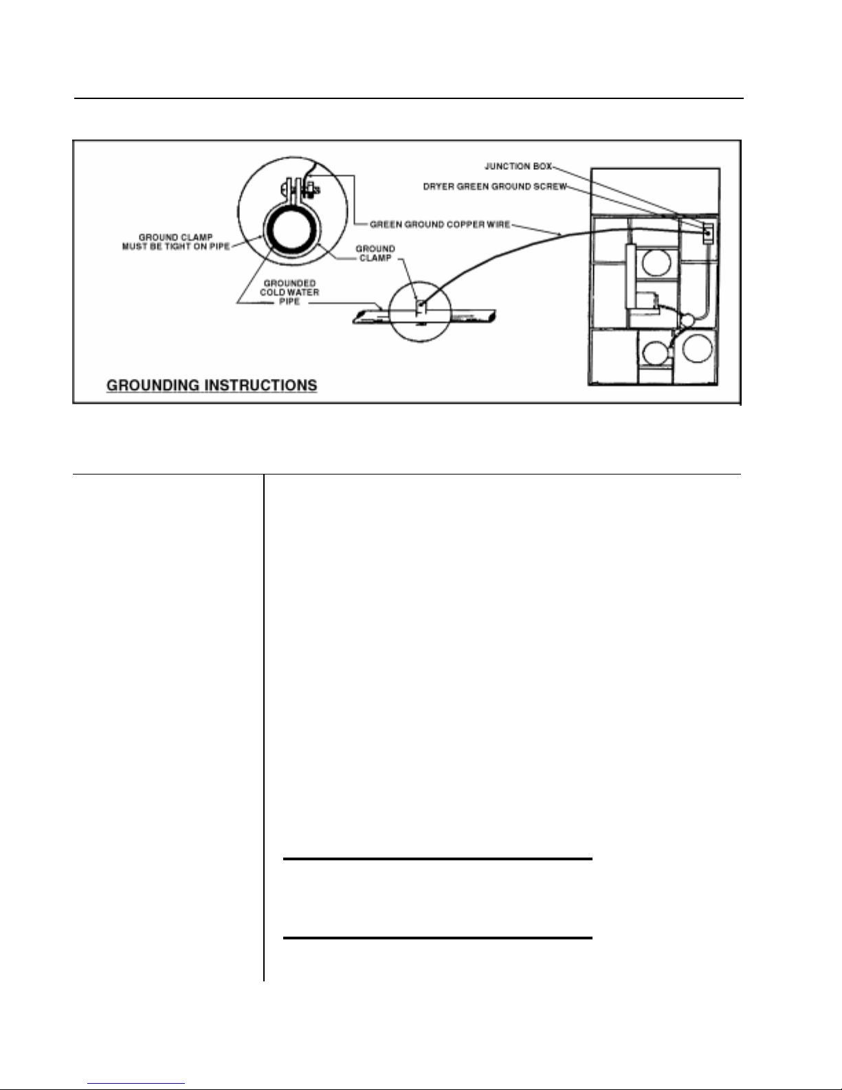
ELECTRICAL CONNECTIONS (WITH GROUNDING INSTRUCTIONS
ELECTRICAL
CONNECTIONS
FOR ALL DRYERS
Dryers must be electrically grounded by a separate #14 or larger
green wire from the grounding terminal within the service connection
box, to a cold water pipe. In all cases, the grounding method must comply
with local electrical code requirements; or in the absence of local
codes, with the National Electrical Code, ANSI/NFPA 70 or the
Canadian Electrical Code, CA C22.1—Latest Edition.
See wiring diagram furnished with dryer. Your dryer is completely
wired at the factory and it is only necessary for the electrician to connect
the power leads to the wire connectors within the service connection box
on the rear of the dryer. Do not change wiring without consulting the
factory, as you may void the factory warranty. DO NOT
CONNECT THE DRYER TO ANY VOLTAGE OR CURRENT
OTHER THAN THAT SPECIFIED ON THE DRYER RATING
PLATE. (Wiring diagram is located on rear wall of dryer.)
All panels must be in position before operation of dryer.
«Attention. Lors des opérations d’entretien
des commandes, ètiqueter tous les fils avant
de les dèconnecter. Toute erreur de câblage
peut être une source de danger et de panne»
Page 16
GAS PIPING
GAS SERVICE
INSTALLATION
INFORMATION
The size of the gas service pipe is dependant upon many variables, such
as tees, lengths, etc. Specific pipe size should be obtained from the gas
supplier. Refer to the Gas Pipe Size Chart in this manual for general gas
pipe size information.
CAUTION
Gas loop piping must be installed as shown in Illustration, to
maintain equal gas pressure for all dryers connected to a
single gas service.
Other gas using appliances should be connected upstream
from the loop.
WARNING
(LIQUIFIED PETROLEUM GASES ONLY)
A Gas Pressure Regulator for Liquified Petroleum Gases is
not furnished on Gas Heated Clothes Dryers. This regulator
is normally furnished by the installer. In accordance with
American Gas Association (AGA) standards, a gas pressure
regulator, when installed indoors, must be equipped with a
vent limiter, or a vent line must be installed from the gas
pressure regulator vent to the outdoors.
Page 17
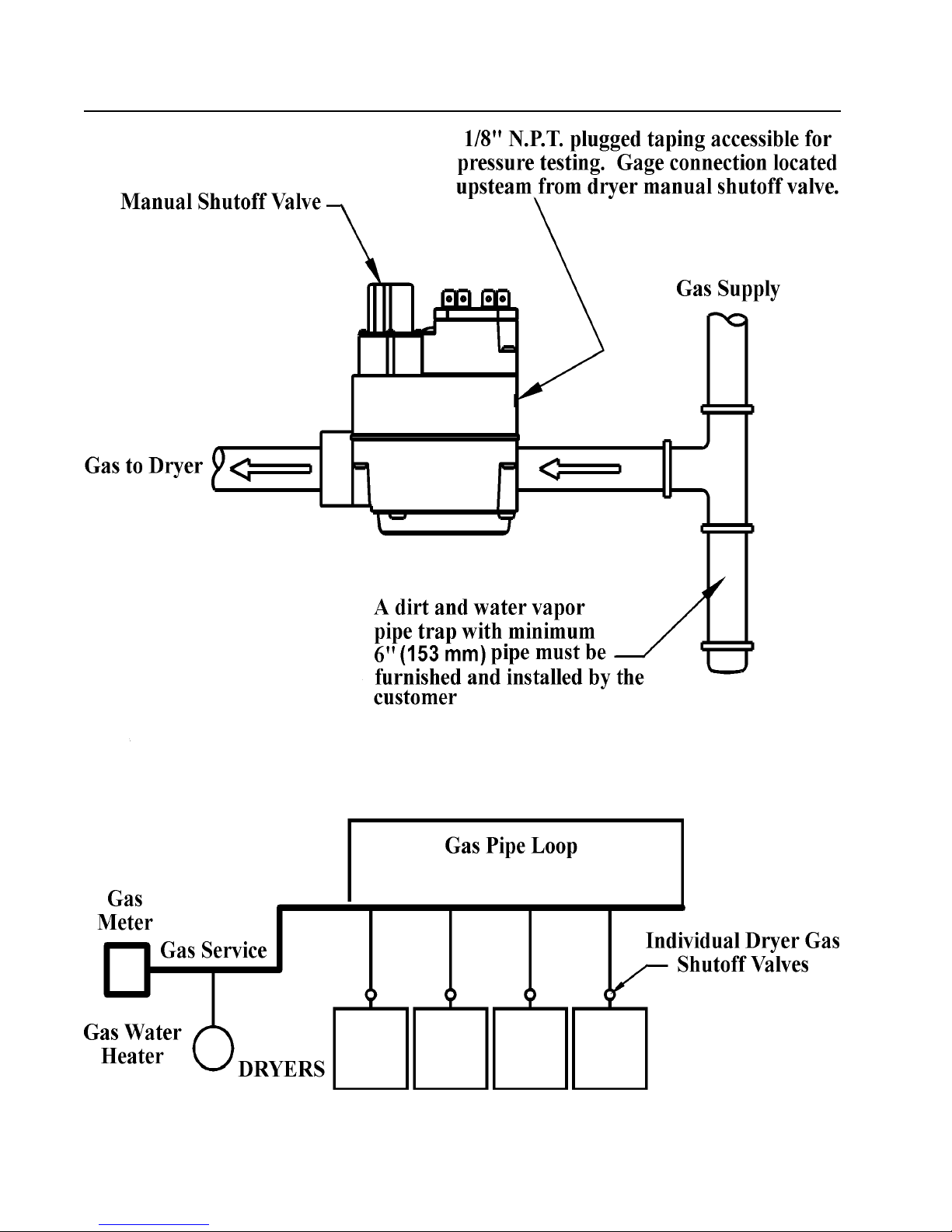
GAS PIPING INSTALLATION (ILLUSTRATION)
Page 18

GAS PIPE SIZE CHART
TOTAL BTU/HR
(for LP Gas correct
total Btu/h below by
multiplying by .6)
60,000
80,000
100,000
120,000
140,000
160,000
180,000
200,000
300,000
400,000
500,000
600,000
700,000
800,000
900,000
1,000,000
1,100,000
1,200,000
1,300,000
1,400,000
1,500,000
1,600,000
1,700,000
1,800,000
1,900,000
2,000,000
2,200,000
2,400,000
2,600,000
2,800,000
3,000,000
3,200,000
3,400,000
3,600,000
3,800,000
4,000,000
TOTAL
KCAL
HOUR
15000
20000
25200
30200
35200
40300
45300
50400
75600
100800
126000
151200
176400
202000
230000
250000
270000
300000
330000
350000
380000
400000
430000
450000
480000
504000
550000
605000
650000
705000
750000
806000
850000
907000
960000
1000000
GAS PIPE SIZE FOR 1000 Btu (252 kcal/h) NATURAL GAS
In figuring total length of pipe, make allowance for tees and elbows.
(25 ft.)
7,62 m
3/4
3/4
3/4
3/4
3/4
3/4
1
1
1
1 1/4
1 1/4
1 1/2
1 1/2
1 1/2
2
2
2
2
2
2
2
2
2
2 1/2
2 1/2
2 1/2
2 1/2
2 1/2
2 1/2
2 1/2
2 1/2
3
3
3
3
3
(50 ft.)
15,24 m
AT 7” w. c. (17.5 bar) PRESSURE
(75 ft.)
22,86 m
3/4
3/4
3/4
1
1
1
1
1
1 1/4
1 1/4
1 1/2
1 1/2
2
2
2
2
2
2
2 1/2
2 1/2
2 1/2
2 1/2
2 1/2
2 1/2
2 1/2
2 1/2
3
3
3
3
3
3
3 1/2
3 1/2
3 1/2
3 1/2
3/4
3/4
1
1
1
1
1
1 1/4
1 1/4
1 1/2
1 1/2
2
2
2
2
2
2 1/2
2 1/2
2 1/2
2 1/2
2 1/2
2 1/2
2 1/2
3
3
3
3
3
3
3
3 1/2
3 1/2
3 1/2
3 1/2
3 1/2
3 1/2
(100 ft.)
30,48 m
3/4
1
1
1
1
1 1/4
1 1/4
1 1/4
1 1/2
1 1/2
2
2
2
2
2 1/2
2 1/2
2 1/2
2 1/2
2 1/2
2 1/2
2 1/2
3
3
3
3
3
3
3
3 1/2
3 1/2
3 1/2
3 1/2
3 1/2
3 1/2
4
4
(125 ft.)
38,1 m
3/4
1
1
1
1
1 1/4
1 1/4
1 1/4
1 1/2
1 1/2
2
2
2
2 1/2
2 1/2
2 1/2
2 1/2
2 1/2
2 1/2
3
3
3
3
3
3
3
3 1/2
3 1/2
3 1/2
3 1/2
3 1/2
3 1/2
4
4
4
4
(150 ft.)
45,72 m
1 1/4
1 1/4
1 1/4
1 1/2
1 1/2
2 1/2
2 1/2
2 1/2
2 1/2
2 1/2
2 1/2
3 1/2
3 1/2
3 1/2
3 1/2
3 1/2
3/4
1
1
1
2
2
2
3
3
3
3
3
3
3
4
4
4
4
4
4
Page 19
GAS PIPING INSTALLATION
GAS PIPING
INSTALLATION
1. The installation must conform to local codes or in absence of local
codes, with the National Fuel Gas Code, ANSI Z223.1 or
the CAN/CGA-B149, Installation Codes.
2. Check with utilities for proper gas pressure and gas supply line.
3. Check the altitude elevation of dryer.
4. The dryer and its individual shut-off valve must be disconnected
from the gas supply piping system at test pressures in excess of 1/
2 psig (.04 bar).
5. The dryer must be isolated from the gas supply piping system by
closing its individual manual shut-off valve during any pressure
testing of the gas supply piping system, at test pressures equal to
or less than 1/2 psig (.04 bar).
NATURAL GAS ONLY
Check the gas pressure inlet supply to the dryer, 11”w.c.
(27.4 bar) pressure maximum. Check the manifold pressure,
3.5”w.c. (8.8 bar) pressure inside the dryer.
CAUTION
Low gas pressure and intermittent gas will cause gas ignition
problems and inadequate drying of the clothes load.
Page 20

Steam Dryers - Option Installation Instructions (When The Steam Bonnet Is Shipped Separate)
STEAM DRYERS -OPTION
INST ALLATION
INSTRUCTIONS
1. The dryer comes in two wood crates:
A - Very large crate
B - Smaller crate
2. Open Crate A and lift dryer off the skid and set in place.
3. Open Crate B. It contains two assemblies:
I - Control Box Assembly
II - Steam Bonnet Assembly
4. Place II - Steam Bonnet Assembly on top of the dryer and
slide piped end to rear of dryer. Bolt to top with six
3/8” ( 10 mm) bolts, flat washers and lockwashers provided.
Attach Solenoid Conduits (2) to the Right Front Control
Box. Then connect the wires as per diagram on the rear
wall of dryer.
5. Place I - Control Box Assembly on top front of the dryer and
bolt in place with six 3/8” (10 mm) bolts, flat washers and
lockwashers. Snap the electrical connections together.
6. Proceed with steam piping, electrical services and duct
work, as specified in technical manual.
Page 21
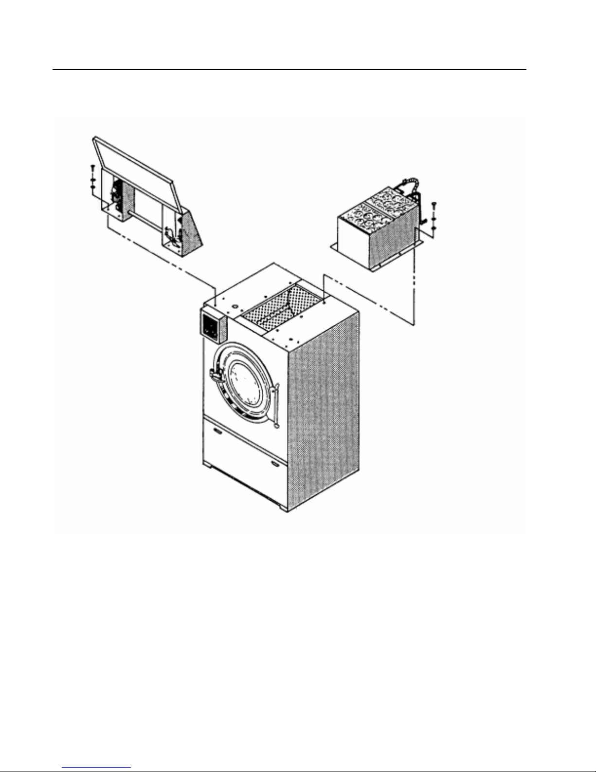
I - Control Box Assembly and II - Steam Bonnet Assembly
(When The Steam Bonnet Is Shipped Seperate)
I - Control Box Assembly II - Steam Bonnet Assembly
Page 22
 Loading...