

50 lb. Sectionalized
Shipboard
Laundry Dryer
Models
L36TD30ME, L36TD30MS
(NSN: 3H 3510-01-340-9419) (NSN: 3H 3510-01-312-4422)
440V. A.C. 60 CYCLE 3 PHASE
TECHNICAL MANUAL
INSTALLATION OPERATION
SERVICE PARTS
CISSELL MANUFACTURING COMPANY
HEADQUARTERS PHONE: (502) 587-1292
831 SOUTH FIRST ST. SALES FAX: (502) 585-3625
P.O. BOX 32270 SERVICE/PARTS FAX: (502) 681-1275
LOUISVILLE, KY 40232-2270
THIS MANUAL MUST BE GIVEN TO THE EQUIPMENT OWNER.
MAN344 1/98 - 5C - WB TECHNICAL MANUAL #S6162-BS-MMC-010/12489
S6162-BS-MMC-010/12489
IMPORTANT NOTICES—PLEASE READ
For optimum efficiency and safety, we recommend that you read the Manual before operating the equipment.
Store this manual in a file or binder and keep for future reference.
WARNING: For your safety, the information in this manual must be followed
to minimize the risk of fire or explosion or to prevent property damage,
personal injury, or loss of life.
- Do not store or use gasoline or other flammable liquids or vapors in the
vicinity of this or any other appliance.
- WHAT TO DO IF YOU SMELL GAS
• Do not try to light any appliances.
• Do not touch any electrical switch; do not use any phone in your building.
• Clear the room, building, or area of all occupants.
• Immediately call your gas supplier from a neighbor's phone. Follow the
gas supplier's instructions.
• If you cannot reach the gas supplier, call the fire department.
Installation and service must be performed by a qualified installer, service
agency or the gas supplier.
WARNING: In the event the user smells gas odor, instructions on what to do must be
posted in a prominent location. This information can be obtained from the local gas
supplier.
WARNING: Wear Safety Shoes to prevent injuries.
WARNING: Purchaser must post the following notice in a prominent location:
FOR YOUR SAFETY
Do not store or use gasoline or other flammable vapors
and liquids in the vicinity of this or any other appliance.
WARNING: A clothes dryer produces combustible lint and should be exhausted
outside the building. The dryer and the area around the dryer should be kept free of
lint.
WARNING: Be safe, before servicing machine, the main power should be shut off.
Page 2
S6162-BS-MMC-010/12489
WARNING: To avoid fire hazard, do not dry articles containing foam rubber or similar
texture materials. Do not put into this dryer flammable items such as baby bed
mattresses, throw rugs,undergarments (brassieres, etc.) and other items which use
rubber as padding or backing. Rubber easily oxidizes causing excessive heat and
possible fire. These items should be air dried.
WARNING: Synthetic solvent fumes from drycleaning machines create acids when drawn
through the dryer. These fumes cause rusting of painted parts, pitting of bright or plated
parts, and completely removes the zinc from galvanized parts, such as the tumbler basket. If
drycleaning machines are in the same area as the tumbler, the tumbler's make-up air must
come from a source free of solvent fumes.
WARNING: Do not operate without guards in place.
WARNING: Check the lint trap often and clean as needed but at least a minimum of once
per day.
WARNING: Alterations to equipment may not be carried out without consulting with the
factory and only by a qualified engineer or technician. Only Cissell parts may be used.
WARNING: Remove clothes from dryer as soon as it stops. This keeps wrinkles from
setting in and reduces the possibility of spontaneous combustion.
WARNING: Be Safe - shut main electrical power and gas supply off externally before
attempting service.
WARNING: Never use drycleaning solvents, gasoline, kerosene, or other flammable liquids
in the dryer.
FIRE AND EXPLOSION WILL OCCUR. NEVER PUT FABRICS
TREATED WITH THESE LIQUIDS INTO THE DRYER. NEVER USE THESE
LIQUIDS NEAR THE DRYER..
WARNING: Never let children play near or operate the dryer. Serious injury could occur if
a child should crawl inside and the dryer is turned on.
WARNING: Never tumble fiberglass materials in the dryer unless the labels say they are
machine dryable. Glass fibers break and can remain in the dryer. These fibers cause skin
irritation if they become mixed with other fabrics.
WARNING: Before operating gas ignition system - purge air from Natural Gas or Propane
Gas Lines per manufacturer’s instructions..
Page 3

S6162-BS-MMC-010/12489
CISSELL DRYER WARRANTY
The Cissell Manufacturing Company (Cissell) warrants all new equipment (and the original parts thereof)
to be free from defects in material or workmanship for a period of two (2) years from the date of sale thereof
to an original purchaser for use, except as hereinafter provided. With respect to non-durable parts normally
requiring replacement in less than two (2) years due to normal wear and tear, and with respect to all new
repair or replacement parts for Cissell equipment for which the two (2) year warranty period has expired,
or for all new repair or replacement parts for equipment other than Cissell equipment, the warranty period
is limited to ninety (90) days from date of sale. The warranty period on each new replacement part furnished
by Cissell in fulfillment of the warranty on new equipment or parts shall be for the unexpired portion of the
original warranty period on the part replaced.
With respect to electric motors, coin meters and other accessories furnished with the new equipment, but
not manufactured by Cissell, the warranty is limited to that provided by the respective manufacturer.
Cissell's total liability arising out of the manufacture and sale of new equipment and parts, whether under
the warranty or caused by Cissell's negligence or otherwise, shall be limited to Cissell repairing or replacing,
at its option, any defective equipment or part returned f.o.b. Cissell's factory, transportation prepaid, within
the applicable warranty period and found by Cissell to have been defective, and in no event shall Cissell be
liable for damages of any kind, whether for any injury to persons or property or for any special or
consequential damages. The liability of Cissell does not include furnishing (or paying for) any labor such
as that required to service, remove or install; to diagnose troubles; to adjust, remove or replace defective
equipment or a part; nor does it include any responsibility for transportation expense which is involved
therein.
The warranty of Cissell is contingent upon installation and use of its equipment under normal operating
conditions. The warranty is void on equipment or parts; that have been subjected to misuse, accident, or
negligent damage; operated under loads, pressures, speeds, electrical connections, plumbing, or conditions
other than those specified by Cissell; operated or repaired with other than genuine Cissell replacement
parts; damaged by fire, flood, vandalism, or such other causes beyond the control of Cissell; altered or
repaired in any way that effects the reliability or detracts from its performance, or; which have had the
identification plate, or serial number, altered, defaced, or removed.
No defective equipment or part may be returned to Cissell for repair or replacement without prior written
authorization from Cissell. Charges for unauthorized repairs will not be accepted or paid by Cissell.
CISSELL MAKES NO OTHER EXPRESS OR IMPLIED WARRANTY, STATUTORY OR OTHERWISE,
CONCERNING THE EQUIPMENT OR PARTS INCLUDING, WITHOUT LIMITATION, A WARRANTY
OF FITNESS FOR A PARTICULAR PURPOSE, OR A WARRANTY OF MERCHANTABILITY. THE
WARRANTIES GIVEN ABOVE ARE EXPRESSLY IN LIEU OF ALL OTHER WARRANTIES, EXPRESS
OR IMPLIED. CISSELL NEITHER ASSUMES, NOR AUTHORIZES ANY PERSON TO ASSUME FOR IT,
ANY OTHER WARRANTY OR LIABILITY IN CONNECTION WITH THE MANUFACTURE, USE OR SALE
OF ITS EQUIPMENT OR PARTS.
For warranty service, contact the Distributor from whom the Cissell equipment or part was purchased. If
the Distributor cannot be reached, contact Cissell.
IDENTIFICATION NAMEPLATE
The Identification Nameplate is located on the rear wall of the dryer. It contains the dryer serial number, product
number, model number, electrical specifications and other important data that may be needed when servicing
and ordering parts, wiring diagrams, etc. Do not remove this nameplate.
Page 4

S6162-BS-MMC-010/12489
TABLE OF CONTENTS
50 LB. SECTIONALIZED
SHIPBOARD LAUNDRY DRYER
PAGE
Model Numbers & Company Address ....................................................... 1
Important Notices .....................................................................2-3
Dryer Warranty ........................................................................ 4
Table of Contents ...................................................................... 5
Warnings, Cautionary Notes and Symbols ..................................................6-7
Front View of Dryer ..................................................................... 8
Rear View of Dryer ..................................................................... 9
Dimensions .......................................................................... 10
Specifications ........................................................................ 11
Break Down Procedure ...............................................................12-14
General Installation ................................................................... 15
Exhaust Duct Information ............................................................... 16
Dryer Installation with Multiple Exhaust ................................................... 17
Dryer Installation with Separate Exhaust .................................................. 18
Dryer Air Flow Installation .............................................................. 19
Steam Piping Installation Instructions ..................................................... 20
Operating Instructions ................................................................. 21
General Maintenance .................................................................. 21
Troubleshooting Chart ................................................................ 22-25
Air Switch Adjustment ................................................................. 26
Gear Reducer Information ............................................................. 27-28
Instructions for Dryers with Reversing Control ............................................... 29
Aligning Basket ....................................................................... 30
Basket & Spider Assembly .............................................................. 31
Overall Assemblies .................................................................. 32-33
Top Bolted Assembly ................................................................... 34
Left Center Bolted Section ............................................................... 35
Right Center Bolted Section ............................................................. 36
Access Door & Control Panel Assembly ..................................................... 37
Thermometer Assembly ................................................................. 38
Bottom Bolted Assembly ................................................................ 39
Back Channel Bolted Assembly ......................................................... 40-41
Fan Assembly ........................................................................ 42
Front Panel and Door Assemblys ......................................................... 43
Lint Door Assembly .................................................................... 44
Small Gear Reducer Assembly ........................................................... 45
Control Box Assembly .................................................................. 46
Electronic Heated Bonnet Assembly ....................................................... 47
Nine Section Steam Bonnet Assembly ...................................................... 48
Thermostat Assembly .................................................................. 49
Wiring Diagrams .................................................................... 50-53
Page 5
S6162-BS-MMC-010/12489
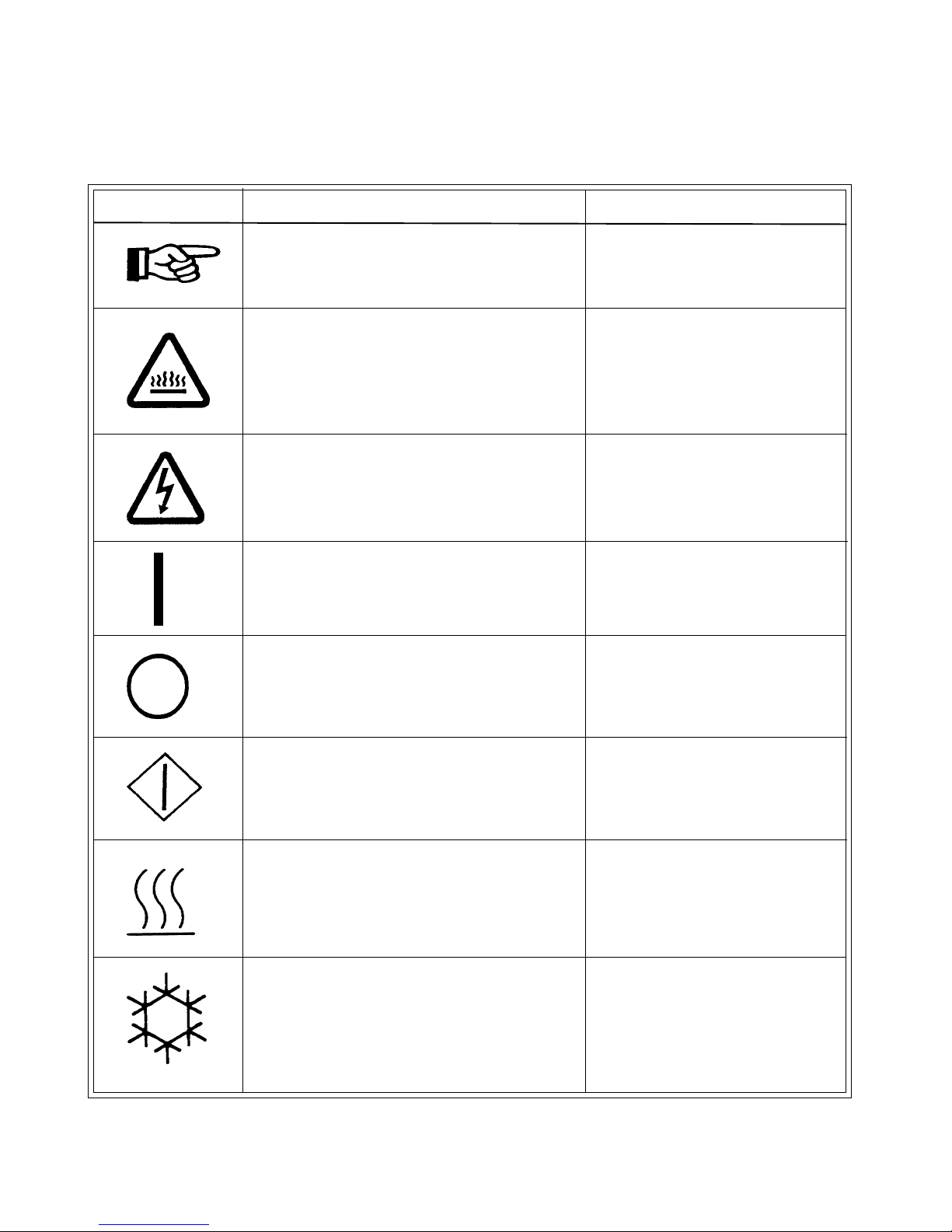
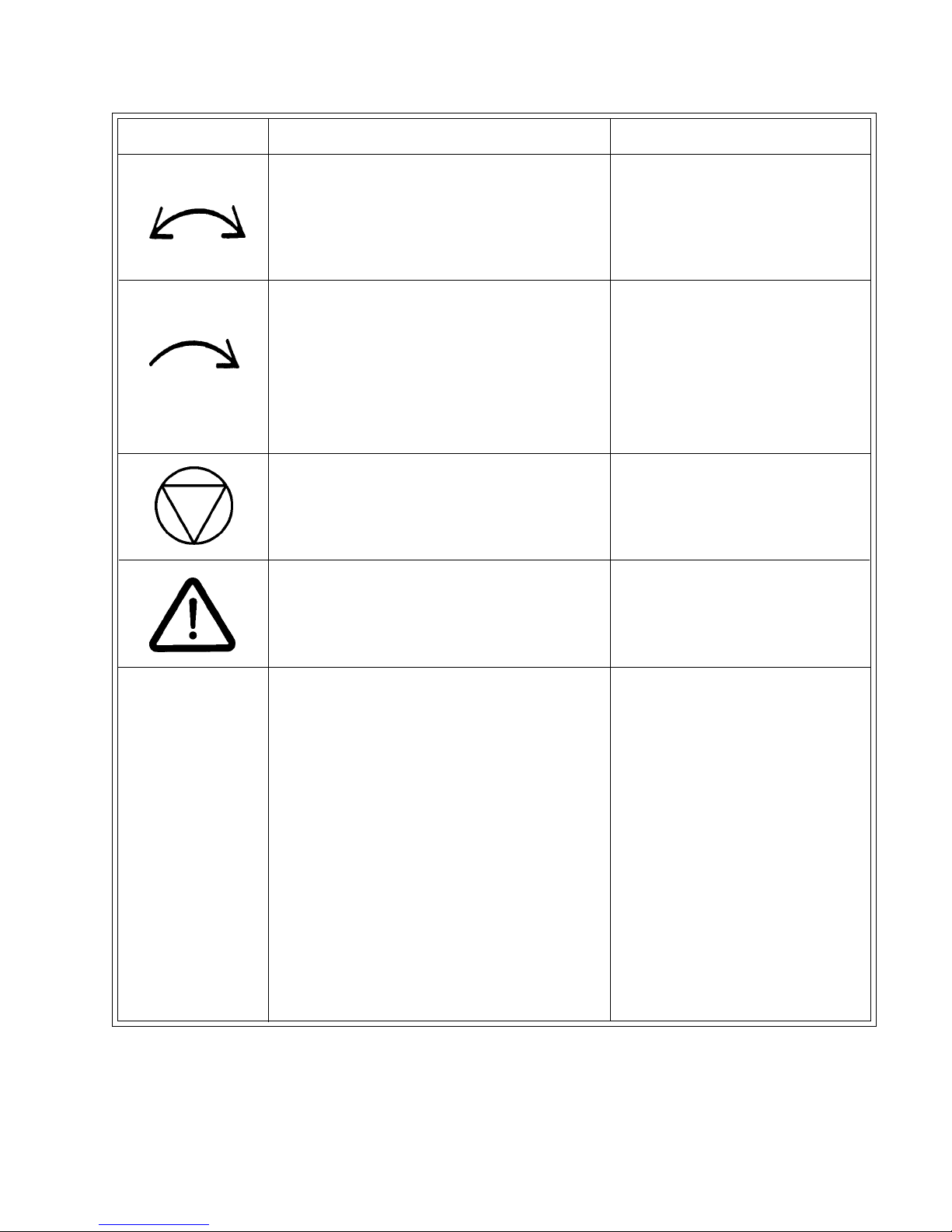
SYMBOLS
The following symbols are used in this manual and/or on the machine. The
numbers between () refer to the numbers on the machine surveys.
Symbol Description Part/Measurement
NOTE!
Hot! Do Not Touch
Heiß! Nicht Beruhren
Haute temperature! Ne pas
toucher
Caliente! no tocar
dangerous voltage
tension dangereuse
Gefährliche elektrische
Spannung
tension peligrosa
on
marche
Ein
conectado
off
arrêt
Aus
desconectado
start
demarrage
Start
arranque de un movimiento
emission of heat in general
êmission de chaleur en
general
Warmeabgabe allgemein
emisión de calor
cooling
refroidissement
Kühlen
enfriamiento
Page 6
S6162-BS-MMC-010/12489
SYMBOLS
Symbol Description Part/Measurement
rotation in two directions
rotation dans les deux sens
Drehbewigung in zwei Richtungen
movimiento rotativo en los dos
sentidos
direction of rotation
sens de mouvement continu de
rotation
Drehbewegung in Pfeilrichtung
movimiento giratorio o rotatorio
en el sentido de la flecha
End of Cycle
caution
attention
Achtung
atencion; precaucion
Page 7
S6162-BS-MMC-010/12489
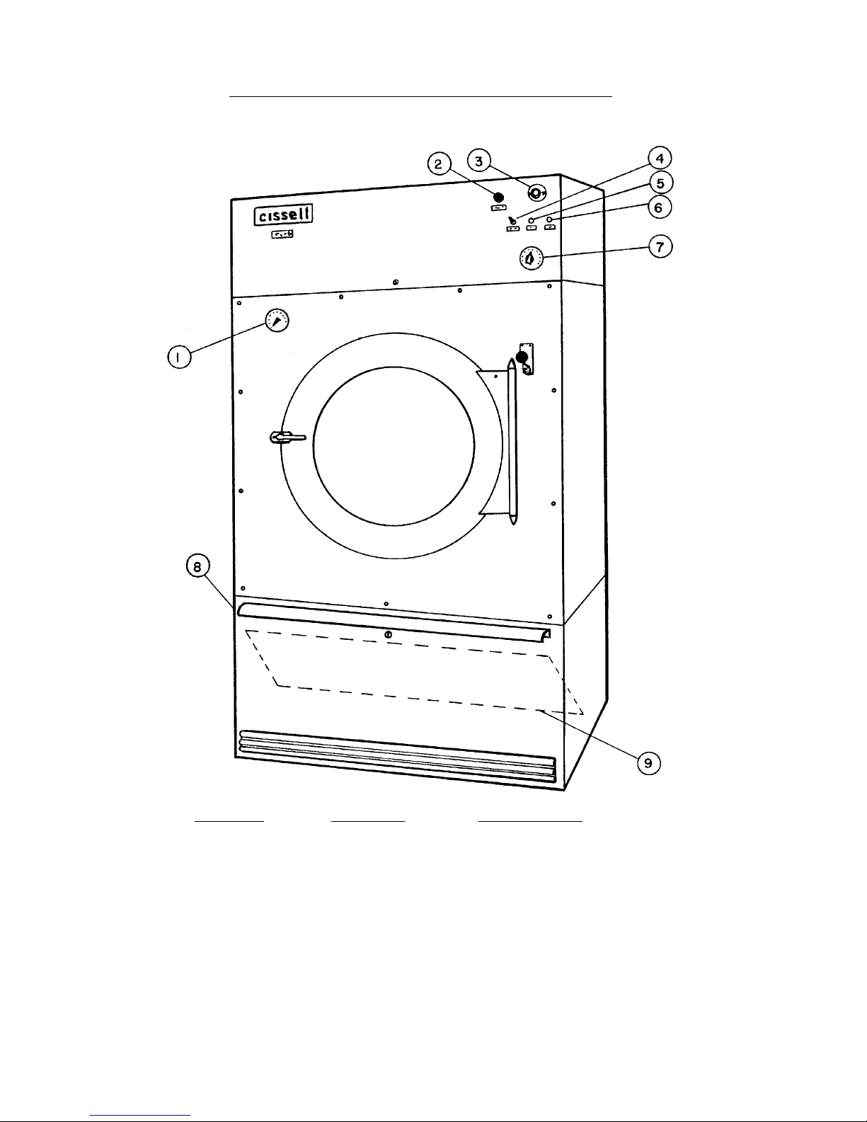
ELECTRIC AND STEAM HEATED DRYERS
FRONT VIEW
Ref. No. Part No. Description
1 TU10528 Thermometer for Basket Temp.
2 PT111 Start Button
3 TU5004 Temperature Range Selector
4 FG147 On/Off Power Switch
5 TU5421 Cool-Down Cycle Lamp
6 TU5421 Drying Cycle Lamp
7 TU4862 Drying Cycle Timer
8 TU10521 Lint Trap Access Door
9 TU5261 Lint Collector Screen
Page 8
19
17
S6162-BS-MMC-010/12489
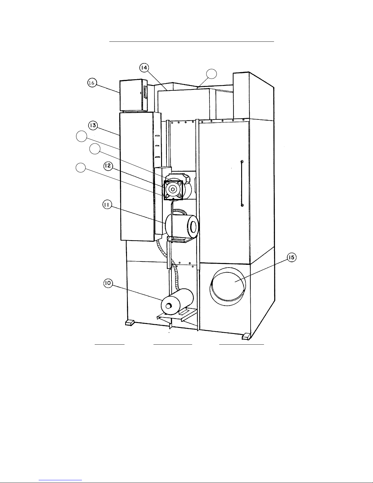
ELECTRIC AND STEAM HEATED DRYERS
REAR VIEW
20
18
Ref. No. PART NO. Description
10 MTR302 Fan Motor
11 MTR302 Basket Motor
12 TM100 Gear Reducer
13 TU11812 Control Box Assembly Steam
14 TU11850 Heating Unit, Electric
15 Exhaust Vent
16 TU10646 Fuses Power Input Disconnect Box
17 TU10917 Cover,Housing
18 TU10916 Housing
19 TU10453 Control Box Assembly Electric
20 TU11202 Heating Unit Steam
Page 9
S6162-BS-MMC-010/12489
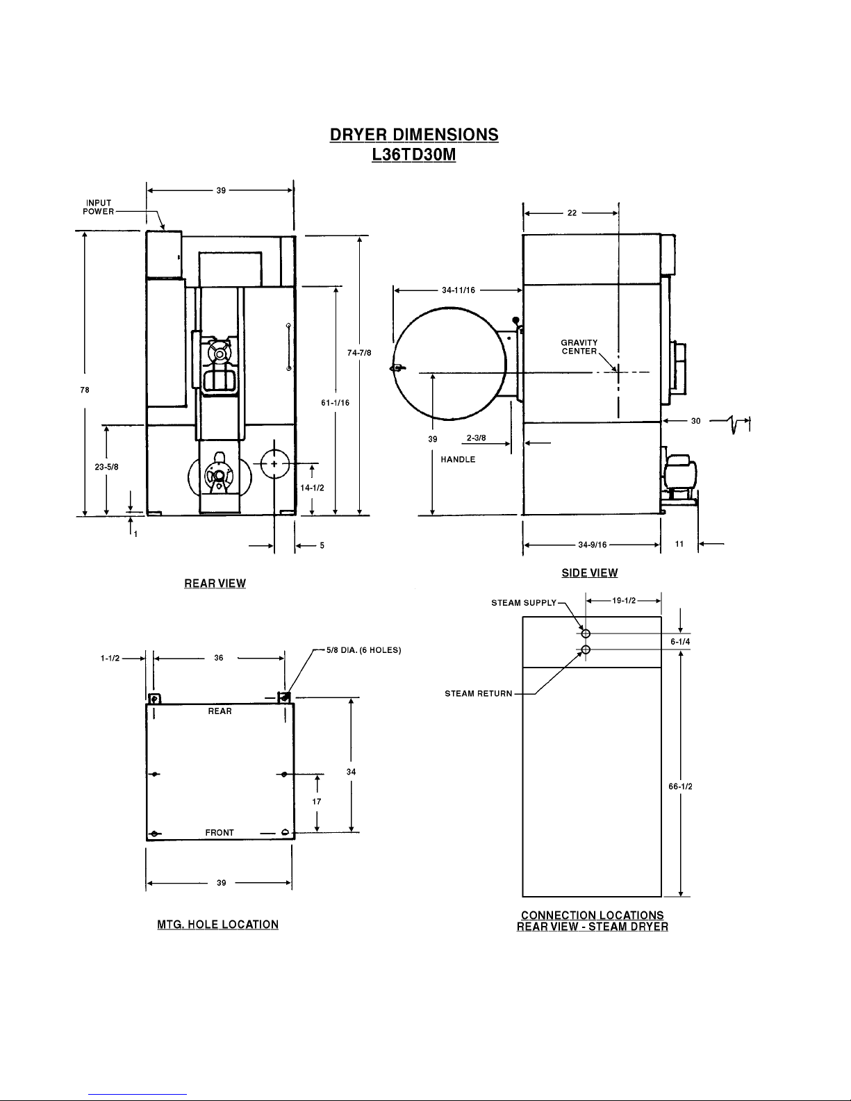
Page 10

S6162-BS-MMC-010/12489
ELECTRIC HEATED
L36TD30ME
Heat Capacity ........................... 36KW
Net Weight (approx.) ...................... 790 lbs.
Domestic Shipping ........................ 1050 lbs.
Weight (carton approx.)
Export Shipping .......................... 1200 lbs.
(1 box approx.)
Export Shipping Dimensions ................ 88” (L) x 45” (W) x 58” (H)
Export Crating ........................... 148 cu. ft.
BASKET LOAD CAPACITY................. 50 LBS. DRYWEIGHT
(For a Maximum Moisture Retention of 100%)
Electrical ............................... 440/60/3 Line Voltage
w/110/60/1 Control Voltage
Total Current ............................ 54 Amps per phase
Basket Motor ............................ 1/2 H.P.
Fan Motor .............................. 1/2 H.P.
Floor Space ............................. 78” High x 39” Wide x 52” Deep
Exhaust Duct ............................ 8” Diameter
Rated Air Displacement .................... 750 CFM at .2” Water Static
Pressure
L36TD30MS
STEAM HEATED - NINE SECTION
Recommended Operating Range ...... 630-730 C.F.M. (17.84 - 20.67 M³/Minute)
Steam Supply Connection ........... 3/4” (1.91 cm)
Steam Return Connection ........... 3/4” (1.91 cm)
Operating Steam Pressure ........... 7 - 15 PSIG (3.18 - 6.8 KG) low pressure
125 PSIG (45.36 KG) Max. high pressure
Drying Time (approximate) .......... 25 lbs. (11.34 KG) dryweight (Indian Head)
80% moisture retention - 30 minutes low
pressure, 22 minutes high pressure
Steam Consumption ................ 2.7 B.H.P. - 90 lbs. (40.7 KG) / Hour with
normal load - Low pressure
................ 3.4 B.H.P. - 117.3 lbs. (53.21 KG) / Hour with
normal load - High pressure
Page 11

S6162-BS-MMC-010/12489
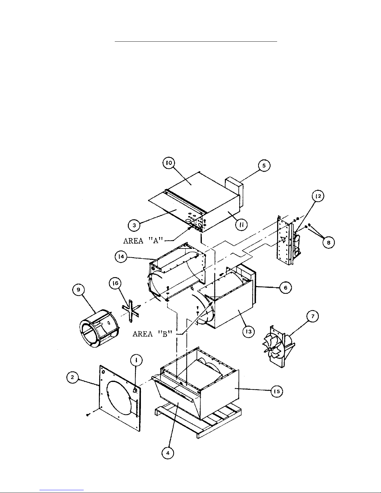
BREAK DOWN PROCEDURE
If the tumbler dryer is installed aboard ship, disconnect the electrical power leads and
steam connections going to the dryer before proceeding further.
NOTE: All wiring is to be left in place unless otherwise noted. Thermometer and
thermostat assembly is left in place.
Back channel, gear reducer, belt guard and motor assembly remains as one
complete assembly.
1. Disconnect door switch (1) by pulling two brown wire connections at Area (B)
after pulling the front door panel off (2). Disconnect the two wire leads from
the white plugs and push them thru opening in Area (B).
2. Remove front panel (2) by unscrewing 11 Phillips head bolts holding it to the
dryer. Two door switch wire leads go with front panel.
3. Remove lint door (4) by turning lock with a screwdriver.
4. Remove cover on reversing control box (6) by unscrewing 2 - hex head bolts.
Pull apart three black leads on top of this control box coming from main
disconnect (5). Disconnect the three red motor leads and three blue motor
leads and two white plugs of wires coming from Area (A). Disconnect the
Greenfield cable nuts from both motor cables and remove from control box.
Disconnect the white Molex connectors and leave in place. Disconnect motor
ground cables (green).
5. Unscrew 4 nuts holding fan motor fan and mount assembly (7) onto back of
dryer.
6. Remove two basket shaft nuts (8) on gear reducer. Then go to front of dryer
and wiggle the basket (9) fromt the dryer. The basket shaft key, 9 inches
long, might stay with shaft; if it doesn’t, remove it from gear reducer and tie
it to the shaft for later use.
Page 12
S6162-BS-MMC-010/12489
BREAK DOWN PROCEDURE (Continued)
7. Go to rear of dryer and remove top cover (10) (Electric Dryer Only) by
unscrewing 2 hex head bolts, then lift top up and pull top to rear of dryer and
remove. Now you are ready for dismantling the dryer.
8. Unscrew twenty-eight 1/4” and four 3/8” hex head bolts holding top
compartment (11) to dryer. Remove top compartment.
(continued next page)
Page 13

S6162-BS-MMC-010/12489
BREAK DOWN PROCEDURE (Continued)
9. Go to the rear of dryer and unscrew fourteen 3/8” nuts holding rear channel,
motor and gear reducer assembly (12) to the dryer.
1 0 . You can remove either the right section (13) or left section (14) next. Going
to front of dryer, unscrew sixteen 1/4” hex head bolts holding either section to
the base. The bolts are located behind the sweep sheets and both in front
and rear of the compartment.
1 1 . Unbolt the bottom section (15) from deck (six 5/8” bolts) or skid (1/4” lag
bolts), whichever it may be.
12. If the Basket (9) must be taken apart to go through the passage ways, first
turn basket on end so shaft is pointing skyward. Notice the markings on
Basket rear and spider I & II, in red. These have to be re-attached at their
same location when you re-assemble including any shims that may be
present under each spider arm (this will keep the basket balanced). Remove
4 nuts from through bolts holding spider (16) to basket (9). Count shims
under each spider arm and retain. Turn basket on its side and drill out 27
rivets on front and 27 rivets on the rear of the basket with the drill bit
provided in kit. These rivets are completely around the circumference of the
basket. Leave the ribs attached. Additional stainless steel and rivet gun are
supplied with the dryer kit. Push both ends out of the basket material and
save the ends. Now gently push sides of basket material in an oblong shape
to pass through your door opening, do not crimp basket material.
To assemble, just proceed in the reverse order.
NOTE: After rewiring fan motor, check fan rotation. See label on fan motor housing
for correct direction. To change rotation, reverse two of the three motor
wires.
Page 14

S6162-BS-MMC-010/12489
GENERAL INSTALLATIONS
The construction of Cissell Cabinet Dryers permits installation side by side to save space or to provide a wall
arrangement. Position dryer for the least amount of exhaust piping and elbows, and allow free access to the
rear of dryer for future servicing of belts, pulleys, and motor.
Before operating dryer, open basket door, remove blocking between front panel and basket; remove all tape used
to secure dryer parts during shipment; level dryer; and read all instruction tags, etc.
DRYER AIR FLOW INSTALLATION
Nothing is more important than air flow for the proper operation of a clothes dryer. A dryer is a pump which
draws make-up air from the out-of-doors, through the heater, through the clothes and then forces the air
through the exhaust duct back to the out-of-doors. Just as in a fluid water pump, there must be a fluid air flow
to the inlet of the dryer if there is to be the proper fluid air flow out of the exhaust duct. In summary, there
must be the proper size out-of-doors inlet air opening (4 to 6 times the combined areas of the air outlet) and an
exhaust duct size and length which allows flow through the dryer with no more than 0.3 inches water column
static pressure in the exhaust duct.
CISSELL WILL PROVIDE FREE ENGINEERING ADVICE FOR ANY
SPECIFIED INSTALLATION
In some instances, a ventilation system with special fans are required to supply make-up air and/or boost
exhaust fans.
EXHAUSTING DUCT
If needed, use adapter to increase 8” dia. duct to 12” dia. duct. Vent the 8” dia. exhaust, on rear of dryer, to
atmosphere. Do not reduce duct size. If vent is vertical through through roof, install two elbows on the discharge end forming a “U” looking down; if vent is horizontal through wall, install one elbow on the discharge end
looking down to prevent wind, rain, snow, sleet, etc., from entering duct and flowing down to dryer.
For multiple dryer installations, it is preferable to vent each dryer individually with a separate duct.
When conditions require the use of a single exhaust duct for several dryers, piping from each dryer should enter
the single duct at an angle of approximately 30°-45°, and in the direction of the air flow. The cross sectional
area of the single exhaust duct should equal the combined areas of the dryer ducts connected to it. Make all
exhaust connections with the least amount of elbows to reduce air resistance to a minimum. Provide cleanout
and inspection openings in the horizontal sections of the duct work and clean periodically. On multiple installations employing a single exhaust duct, there should be no back draft to interfere with the normal free discharge
of air from each dryer.
Before approving duct installation, place each dryer in operation; progressively open each dryer door, manually
trip door switch, and see that air is drawn into the basket door opening as freely as it is when all other dryers
are stopped.
Keep the exhaust ducts clean. Do not install wire mesh or screen in the exhaust ducts as lint will build up and
prevent discharge of air from dryers. Keep inside surfaces smooth. Pop rivets are recommended for duct
assembly.
MAKE-UP AIR
If possible, provide opening to the room where the dryer is a minimum of 2 square feet make-up air for each
dryer.
Scorched clothes, slow drying, lint accumulations, or air switch malfunction are indicators of exhaust and/or
make-up air problems.
TROUBLESHOOTING
Page 15
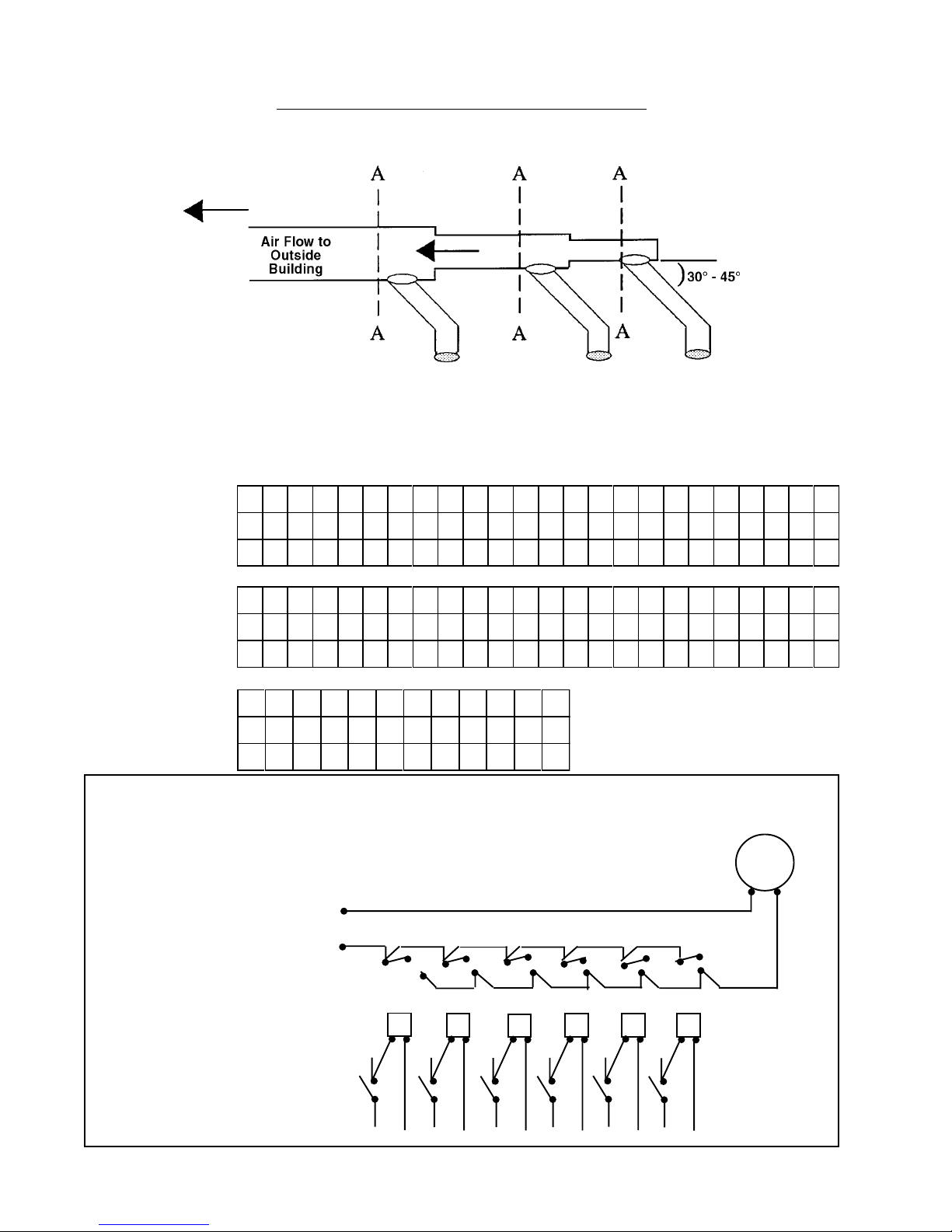
No. of Dryers
Duct Diameter
(in inches)
(in CM)
No. of Dryers
Duct Diameter
(in inches)
(in CM)
No. of Dryers
Duct Diameter
(in inches)
(in CM)
S6162-BS-MMC-010/12489
EXHAUST DUCT INFORMATION
For Exhaust Duct less than 14 feet and 2 elbows
equivalent and less than 0.3 inches static pressure.
DRYER EXHAUSTS
Area of section “A-A” must be equal to the sum of dryer exhaust pipes
entering multiple exhaust pipe. (
MODELS: L28FD30, L28US30, L36FD30, L36UR30, L36CD36, L44FD42
1 2 3 4 5 6 7 8 9 10 11 12 13 14 15 16 17 18 19 20 21 22 23 24
6 9 11 12 14 15 16 17 18 19 20 21 22 23 23 24 25 26 26 27 28 28 29 30
15 23 27 30 35 38 41 43 46 48 51 53 56 58 58 61 63 66 66 68 71 71 73 76
MODELS: L28CD30, L28UR30, L36CD30, L36UR30, L36CD36, L44FD42
1 2 3 4 5 6 7 8 9 10 11 12 13 14 15 16 17 18 19 20 21 22 23 24
8 12 14 16 18 20 22 23 24 26 27 28 29 30 31 32 33 34 35 36 37 38 39 40
20 30 35 41 46 51 56 58 61 66 68 71 73 76 78 81 84 86 89 91 94 97 99 100
MODELS: L44CD42, L50CD42
1 2 3 4 5 6 7 8 9 10 11 12
12 17 21 24 27 30 32 34 36 38 40 42
30 43 53 61 68 76 81 86 91 97 100 106
See chart below.
)
AUTOMATIC ELECTRICAL CONTROL FOR EXHAUST FAN
For one or more dryers to start fan.
Power Supply
to Fan
Relay Coils
Start and Stop
Switches on
Dryers
_ _
_ _
_ _
_ _
Page 16
_ _
_ _
Exhaust
Booster Fan
_ _
_ _
_ _
_ _
_ _
_ _
 Loading...