

Cissell GEARCAB, Gear Cabinet User Manual
Gear Cabinet
Owners manual
With DMP Control
Gear
Cabinet
GEARCAB 12/02
Cissell Manufacturing Co.
831 S. First St. - P.O.Box 32270 - Louisville, Ky. - 40232-2270
Tel: (502) 587-1292 - Fax: (502) 585-2333 -
Sales Fax: (502) 585-3625 - Service/Parts Fax: (502) 681-1275
Page 1

WARRANTY
Cissell Manufacturing Company (Cissell) warrants all new equipment (and the original parts thereof) to be
free from defects in material or workmanship for a period of one (1) year from the date of sale thereof to an original
purchaser for use, except as hereinafter provided. With respect to non-durable parts normally requiring replacement in
less than one (1) year due to normal wear and tear, including but not limited to, cloth goods, valve discs, hoses and iron
cords, and with respect to all new repair or replacement parts for Cissell equipment for which the one (1) year warranty
period has expired or for all new repair or replacement parts for equipment other than Cissell equipment, the warranty
period is limited to ninety (90) days from date of sale. The warranty period on each new replacement part furnished by
Cissell in fulfillment of the warranty on new equipment or parts shall be for the unexpired portion of the original
warranty period on the part replaced.
With respect to electric motors, coin meters and other accessories furnished with the new equipment, but not manufactured by Cissell, the warranty is limited to that provided by the respective manufacturer.
Cissells total liability arising out of the manufacture and sale of new equipment and parts, whether under the warranty
or caused by Cissells negligence or otherwise, shall be limited to Cissell repairing or replacing, at its option, any
defective equipment or part returned f.o.b. to Cissells factory, transportation prepaid, within the applicable warranty
period and found by Cissell to have been defective, and in no event shall Cissell be liable for damages of any kind,
whether for any injury to persons or property or for any special or consequential damages. The liability of Cissell does
not include furnishing (or paying for) any labor such as that required to service, remove or install; to diagnose troubles;
to adjust, remove or replace defective equipment or a part; nor does it include any responsibility for transportation
expense which is involved therein.
The warranty of Cissell is contingent upon installation and use of its equipment under normal operating conditions.
The warranty is void on equipment or parts that have been subjected to misuse, accident or negligent damage; operated
under loads, pressures, speeds, electrical connections, plumbing, or conditions other than those specified by Cissell;
operated or repaired with other than genuine Cissell replacement parts; damaged by fire, flood, vandalism, or such
other causes beyond the control of Cissell; altered or repaired in anyway that affects the reliability or detracts from its
performance; or which have had the identification plate or serial number altered, effaced or removed.
No defective equipment or part may be returned to Cissell for repair or replacement without prior written authorization
from Cissell. Charges for unauthorized repairs will not be accepted or paid by Cissell.
CISSELL MAKES NO OTHER EXPRESSED OR IMPLIED WARRANTY, STATUTORY OR OTHERWISE, CONCERNING THE EQUIPMENT OR PARTS INCLUDING, WITHOUT LIMITATION, A WARRANTY OF FITNESS FOR A
PARTICULAR PURPOSE, OR A WARRANTY OF MERCHANTABILITY. THE WARRANTIES GIVEN ABOVE ARE
EXPRESSLY IN LIEU OF ALL OTHER WARRANTIES, EXPRESSED OR IMPLIED. CISSELL NEITHER ASSUMES
NOR AUTHORIZES ANY PERSON TO ASSUME FOR IT ANY OTHER WARRANTY OR LIABILITY IN CONNECTION WITH THE MANUFACTURE, USE OR SALE OF ITS EQUIPMENT OR PARTS.
For warranty service, contact the Distributor from whom the Cissell equipment or part was purchased. If the Distributor cannot be reached, contact Cissell.
Page 2
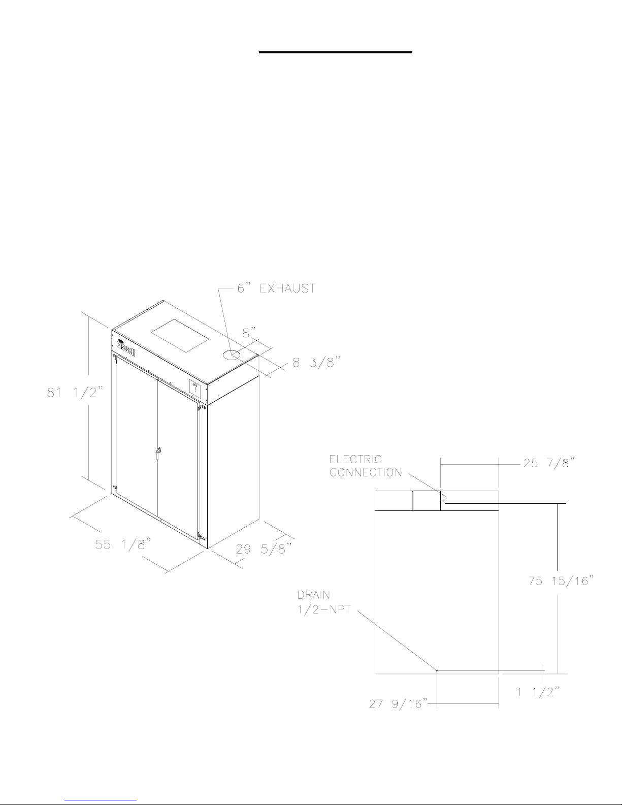
SPECIFICATIONS
Width, Overall 55 1/8" (1400 mm)
Depth, Overall 30 13/16" (783 mm)
Height, Overall 81 1/2" (2070 mm)
Domestic Shipping Weight (approx.) AGC64 - 250 lbs. (113 kg)
AGC65 - 250 lbs. (113 kg)
AGC44 - 250 lbs. (113 kg)
AGC45 - 250 lbs. (113 kg)
Electrical Requirements (AGC64) 240V., 50/60 Hz., 1 PH., 51 amps, Fuse 60A
(AGC65) 240V., 50/60 Hz., 3 PH., 30 amps, Fuse 35A
(AGC44) 208V., 60 Hz., 1 PH., 60 amps, Fuse 70A
(AGC45) 208V., 60 Hz., 3 PH., 35 amps, Fuse 40A
ALL DIMENSIONS ARE
+/- 1/4 (+/- 6.4 mm) AND ARE
SUBJECT TO CHANGE WITH-
OUT NOTICE
REAR VIEW
Page 3

TESTING
The Cissell Gear Cabinets are manufactured and tested to the highest standards.
This Gear Cabinet has been tested in the Cissell factory to determine that it is safe and in working
order.
This Gear Cabinet has been tested to UL and CSA standards.
GEAR PREPERATION
The gear should be washed separatley , DO NOT WASH LINER AND SHELL TOGATHER!
The gear should not be re-assembled before hanging in the cabinet.
The unit will dry two complete sets of gear at one time (shells and liners), plus boots or gloves. The
grear should be staggered, liner, shell , liner, shell, etc.
Page 4

TABLE OF CONTENTS
PAGE
Warranty: 2
Specifications: 3
Testing: 4
Gear Preperation: 4
Table of Contents: 5
Diagnostic Micropressor Control:
Features 6-9
Installing the Gear Cabinet: 10
Layout Foot Print 10
Gear Cabinet Assembly Part Numbers:
Main Assembly 11
Bonnet Assembly 12
Heater Assembly 240V 1 & 3 Phase 13
208V 1 Phase 14
208V 3 Phase 15
Wiring Schematics:
AGC65 (240V/60/3) FRW100 16
AGC64 (240V/60/1) FRW110 17
AGC45 (208V/60/3) FRW150 18
AGC44 (208V/60/1) FRW210 19
Ladder Diagram:
AGC65 (240V/60/3) SCH100 20
AGC64 (240V/60/1) SCH110 21
AGC45 (208V/60/3) SCH150 22
AGC44 (208V/60/1) SCH210 23
Page 5

DIAGNOSTIC MICROPROCESSOR CONTROL - FEATURES
Diagnostic Microprocessor Control (DMP)
General Operation
1.0
The Cissell Diagnostic Microprocessor Control (DMP) is designed to manage the drying and cooling cycles
of the gear cabinet. The controller is also programmed from the the factory with five different default pro
grams as described below. The operator has the flexibility to select the time for the drying and cool down
cycles and the drying temperature. The operator may also re-program the default programs. See
paragragh 4.0.
Default Programs
Programs
1
2
3
4
5
Note: If a modified program is determined to be corrupted, the default program settings will be used.
2.0
Features
1. Drying time: 0-180 minutes
2. Cooling time: 2-60 minutes
3. LED display of cycle time, set temperature, and actual temperature
4 Thermistor controlled temperature
5. Buzzer for end of cycle, audible alarm
6. Five user programmable programs
7. Monitors the thermistor for operation
8. Reversing button is not used in this application
Dry Time
90 Minutes
120 Minutes
150 Minutes
180 Minutes
20 Minutes
Cool Time
2 Minutes
2 Minutes
2 Minutes
2 Minutes
2 Minutes
Temp. Set Point
110°F (43°C)
110°F (43°C)
110°F (43°C)
110°F (43°C)
110°F (43°C)
Reversing
N/A
N/A
N/A
N/A
N/A
The minimum drying time is 0 minutes, and the minimum cooling time is 2 minutes. The maximum
drying or cooling time is 180 minutes. The drying temperature may be set from 100°F (38°C) to
150°F (66°C). The drying time, cooling time, or temperature may be modified during an operating
cycle.
If necessary to reset the drying and cooling times for the current cycle, press STOP once to stop
the gear cabinet. Press STOP again to cancel the cycle.
Page 6

DIAGNOSTIC MICROPROCESSOR CONTROL - FEATURES
3.0 DIP Switch Settings
The DMP has an 8-position DIP switch bank that is accessible from the back of the control board. By
switching these DIP switches, it is possible for the operator to customize the display and some of the
operating features of the dryer.
Factory Settings
Switch #
1
2
3
4
5
6
7
8
Function
Gear Cabinet
Temperature Units
Not Used
Not Used
Not Used
Buzzer Timer
Not Used
Programming
OPL
OFF
OFF
ON
ON
ON
ON
ON
OFF
#1 Gear cabinet.
#2 Temperature Units: Selects °F or °C for the temperature display. Factory setting is for °F.
#3 Not used in this application.
#4 Not used in this application.
#5 Not used in this application.
#6 Buzzer Time: This Dip switch determines the length of time that the end of cycle buzzer will remain
on. OFF indicates that the buzzer will sound for 5 seconds when the drying cycle is completed.
ON indicates that the buzzer will sound continuously until the STOP button is pressed.
#7 Not used in this application.
#8 Programming: This switch enables or disables the programming feature.
Page 7

DIAGNOSTIC MICROPROCESSOR CONTROL - FEATURES
4.0 Programming
4.1 Set Dip Switch #8 to the ON position.
4.2 Select the desired program number to change. The LED should be flashing.
4.3 Select DRY TIME. Set the time with the UP/DOWN arrows.
4.4 Select COOL TIME. Set the time with the UP/DOWN arrows.
4.5 Select TEMPERATURE. Set the temperature with the UP/DOWN arrows.
4.6 Press and hold the PROGRAM button about 3 seconds until the LED stops flashing. The selected program
number is now programmed. If the PROGRAM button is pressed for less than 3 seconds, the controller will
cancel the program and display the next programs settings. If not programmed correctly, the display will flash
E2F for 4 seconds, and the default settings will be used. Follow steps 4.2 through 4.7 to re-program any
program number. When finished, set DIP Switch #8 to OFF. The programs are now stored.
4.7 During the program mode, if the UP/DOWN arrows, REV, or DISPLAY button is not pressed within 10
seconds the default program settings will be used.
5.0 Temporary Re-Programming of Current Programs (OPL only)
5.1 The Drying Time, Cooling Time, Temperature, and Reversing Mode of a program currently in use may be
modified simply by adjusting any or all of the program parameters for that program, as needed. Once a
modification has been made the current program LED will flash indicating that it has been modified.
5.2 Use the UP/DOWN arrows to adjust program time.
5.3 Use the Display Select button to choose between Drying Time, Cooling Time, and Temperature. Then use
the UP/DOWN arrows to adjust the times and temperature.
5.4 To cancel this temporary programming mode push the STOP button once to stop the current cycle and once
more to cancel the modified program settings. The program will revert back to its original settings.
6.0 Operational Check for the Board Diagnostics
6.1 Cycle the gear cabinet to check if the buzzer activates.
6.2 The display will read P-F if the thermistor is short circuited or open circuited.
7.0 Description of the Control Panel (See illustration on page 5)
1. START. Starts or resumes the current program or cycle.
2. STOP. Temporarily halts the current cycle or cancels the current program.
3. REVERSING/NON-REVERSING (REV). Not used in this application.
3.1 REVERSING LED. Will illuminate if reversing is pushed but has no effect on operation.
4. UP/DOWN ARROWS. Increases or decreases the value in the display. In conjunction with the
DISPLAY button, these buttons are used to adjust the drying time, cooling time, tempera ture, clockwise time, dwell time, counter-clockwise time, and minutes per coin (COIN only).
4.1 DISPLAY. Displays the drying time, cooling time, drying temperature, and diagnostics.
5. DISPLAY SELECT. Toggles the display between the drying time, cooling time, and temperature
settings. Pressing the DISPLAY button for 3 seconds allows the user to display the drying cycle
temperature.
5.1 DRYING LED. Illuminated when in the drying cycle.
Page 8
 Loading...