

Cissell FMMAN58, FMCD, FMFC, FMJC, FMGG Owner's Manual
...
FMFM
FM
FMFM
FF
F
FF
FF
F
FF
ModelsModels
Models
ModelsModels
FMCD FMFCFMCD FMFC
FMCD FMFC
FMCD FMFCFMCD FMFC
FMGG FMMMFMGG FMMM
FMGG FMMM
FMGG FMMMFMGG FMMM
oo
o
oo
inisherinisher
inisher
inisherinisher
rmrm
rm
rmrm
/ /
FMJCFMJC
/
FMJC
FMJCFMJC
/ /
/ /
/
/ /
FMLMFMLM
FMLM
FMLMFMLM
OWNER’S MANUOWNER’S MANU
OWNER’S MANU
OWNER’S MANUOWNER’S MANU
CISSELL MANUFACTURING COMPANYCISSELL MANUFACTURING COMPANY
CISSELL MANUFACTURING COMPANY
CISSELL MANUFACTURING COMPANYCISSELL MANUFACTURING COMPANY
HEADQUARTERSHEADQUARTERS
HEADQUARTERS PHONE: (502) 587-1292
HEADQUARTERSHEADQUARTERS
831 SOUTH FIRST ST. SALES FAX: (502) 585-3625
P.O. BOX 32270 SERVICE/PARTS FAX: (502) 681-1275
LOUISVILLE, KY 40232-2270
THIS MANUTHIS MANU
THIS MANU
THIS MANUTHIS MANU
MAN58 5/96MAN58 5/96
MAN58 5/96
MAN58 5/96MAN58 5/96
AL MUST BE GIVEN AL MUST BE GIVEN
AL MUST BE GIVEN
AL MUST BE GIVEN AL MUST BE GIVEN
Page 1Page 1
Page 1
Page 1Page 1
ALAL
AL
ALAL
TT
O O
THE EQUIPMENT OWNER.THE EQUIPMENT OWNER.
T
O
THE EQUIPMENT OWNER.
TT
O O
THE EQUIPMENT OWNER.THE EQUIPMENT OWNER.

WARRANTYWARRANTY
WARRANTY
WARRANTYWARRANTY
The Cissell Manufacturing Company (Cissell) warrants all new equipment (and the original parts thereof)
to be free from defects in material or workmanship for a period of one (1) year from the date of sale thereof
to an original purchaser for use, except as hereinafter provided. With respect to non-durable parts normally
requiring replacement in less than one (1) year due to normal wear and tear, including, but not limited to,
cloth goods, valve discs, hoses, and iron cords, and with respect to all new repair or replacement parts for
Cissell equipment for which the one (1) year warranty period has expired, or for all new repair or
replacement parts for equipment other than Cissell equipment, the warranty period is limited to ninety (90)
days from date of sale. The warranty period on each new replacement part furnished by Cissell in fulfillment
of the warranty on new equipment or parts shall be for the unexpired portion of the original warranty period
on the part replaced.
With respect to electric motors, coin meters and other accessories furnished with the new equipment, but
not manufactured by Cissell, the warranty is limited to that provided by the respective manufacturer.
Cissell's total liability arising out of the manufacture and sale of new equipment and parts, whether under
the warranty or caused by Cissell's negligence or otherwise, shall be limited to Cissell repairing or replacing,
at its option, any defective equipment or part returned f.o.b. Cissell's factory, transportation prepaid, within
the applicable warranty period and found by Cissell to have been defective, and in no event shall Cissell be
liable for damages of any kind, whether for any injury to persons or property or for any special or
consequential damages. The liability of Cissell does not include furnishing (or paying for) any labor such
as that required to service, remove or install; to diagnose troubles; to adjust, remove or replace defective
equipment or a part; nor does it include any responsibility for transportation expense which is involved
therein.
The warranty of Cissell is contingent upon installation and use of its equipment under normal operating
conditions. The warranty is void on equipment or parts; that have been subjected to misuse, accident, or
negligent damage; operated under loads, pressures, speeds, electrical connections, plumbing, or conditions
other than those specified by Cissell; operated or repaired with other than genuine Cissell replacement
parts; damaged by fire, flood, vandalism, or such other causes beyond the control of Cissell; altered or
repaired in any way that effects the reliability or detracts from its performance, or; which have had the
identification plate, or serial number, altered, defaced, or removed.
No defective equipment or part may be returned to Cissell for repair or replacement without prior written
authorization from Cissell. Charges for unauthorized repairs will not be accepted or paid by Cissell.
CISSELL MAKES NO OTHER EXPRESS OR IMPLIED WARRANTY, STATUTORY OR OTHERWISE,
CONCERNING THE EQUIPMENT OR PARTS INCLUDING, WITHOUT LIMITATION, A WARRANTY
OF FITNESS FOR A PARTICULAR PURPOSE, OR A WARRANTY OF MERCHANTABILITY. THE
WARRANTIES GIVEN ABOVE ARE EXPRESSLY IN LIEU OF ALL OTHER WARRANTIES, EXPRESS
OR IMPLIED. CISSELL NEITHER ASSUMES, NOR AUTHORIZES ANY PERSON TO ASSUME FOR IT,
ANY OTHER WARRANTY OR LIABILITY IN CONNECTION WITH THE MANUFACTURE, USE OR SALE
OF ITS EQUIPMENT OR PARTS.
For warranty service, contact the Distributor from whom the Cissell equipment or part was purchased. If
the Distributor cannot be reached, contact Cissell.
Page 2Page 2
Page 2
Page 2Page 2
Page 3Page 3
Page 3
Page 3Page 3
CISSELLCISSELL
CISSELL
CISSELLCISSELL
GARMENT MANUFACTURERSGARMENT MANUFACTURERS
GARMENT MANUFACTURERS
GARMENT MANUFACTURERSGARMENT MANUFACTURERS
FORMSFORMS
FORMS
FORMSFORMS
TYPICAL INSTTYPICAL INST
TYPICAL INST
TYPICAL INSTTYPICAL INST
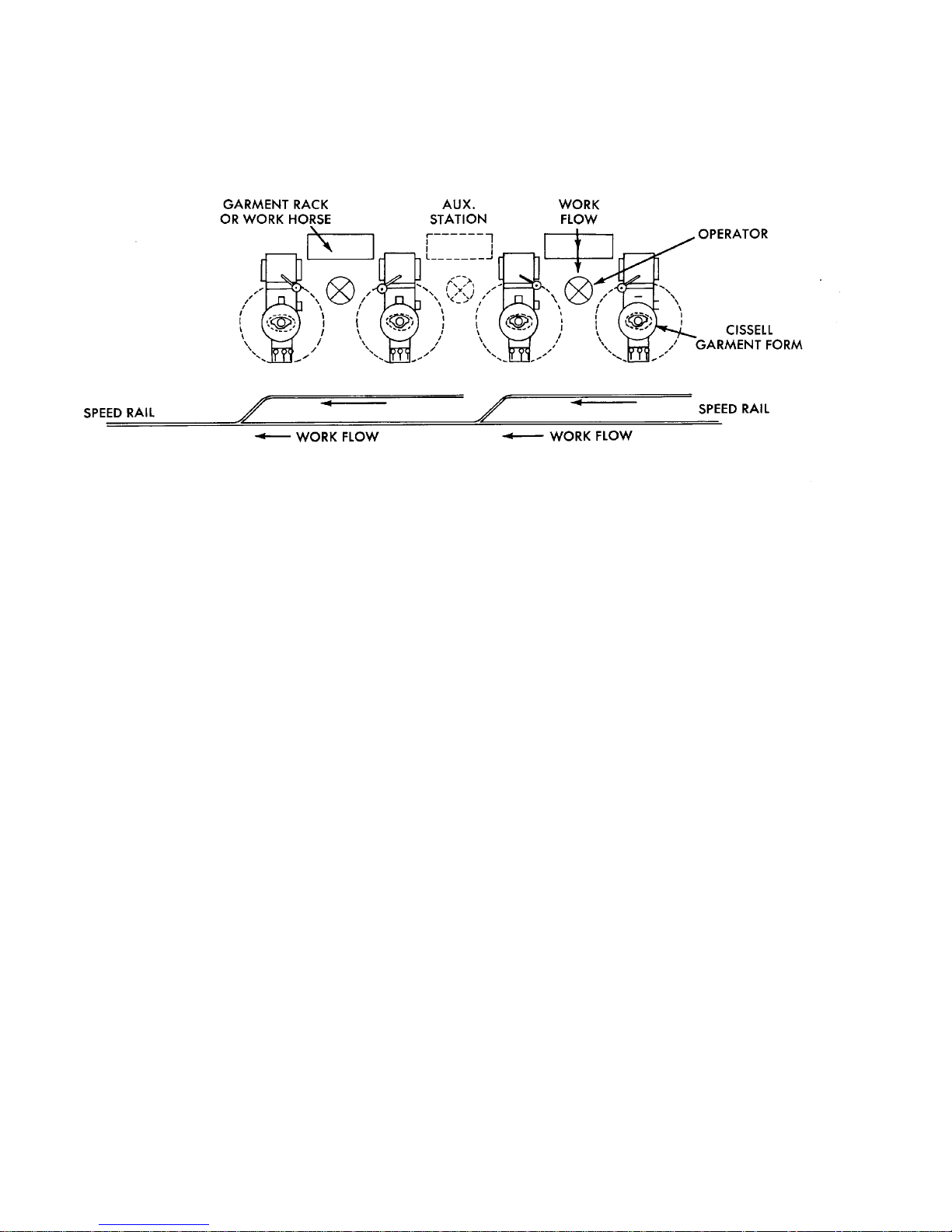
GARMENTS ARE RECEIVED ON RACK OR WORK HORSE ADJACENT TO
FINISHING OPERATOR.
ALLAALLA
ALLA
ALLAALLA
TIONTION
TION
TIONTION
TUBULAR GARMENTS (DRESSES, BUTTONED COATS, ETC.) MAY BE BUNDLED
AND PLACED ON A WORK HORSE, FRONT UPWARD, WITH HEM TOWARD
THE OPERATOR. OPERATOR CAN GRASP EACH GARMENT BY THE HEM
AND SLIP IT OVER THE FORM.
GARMENTS ON HANGERS MAY BE RECEIVED ON RACKS. OPERATOR CAN
REMOVE HANGER FROM A GARMENT, CARRY THE GARMENT OVER ONE
ARM, AND HANG THE PREVIOUSLY FINISHED GARMENT ON THE SPEED
RAIL CARRIER OR ANOTHER RACK. THE UNFINISHED GARMENT CAN
THEN BE PLACED ON THE FORM. WHILE IT IS BEING STEAMED AND
DRIED, THE NEXT GARMENT CAN BE PICKED UP AND HANGER REMOVED.
MAXIMUM PRODUCTION OF HEAVY GARMENTS WITH LONG STEAM AND DRY
CYCLES CAN BE UNLOADED AND RELOADED WHILE THE FIRST IS
STEAMING AND DRYING. LIGHT WEIGHT GARMENTS WITH VERY
SHORT STEAM AND DRY CYCLES PERMIT MAXIMUM PRODUCTION
WITH ONE OPERATOR WORKING ONE FORM. OPERATORS PREPARE
THE NEXT GARMENT OR OBTAIN A HANGER DURING THE STEAM AND
DRY CYCLE.
SUGGESTED FORM CENTERS ARE APPROXIMATELY 4’ 6” SO THAT THE FORMS
CAN BE OPERATED INDIVIDUALLY OR IN PAIRS AS SHOWN BY
POSITION OF AUX. STATION IN DRAWING ABOVE.
Page 4Page 4
Page 4
Page 4Page 4

CISSELLCISSELL
CISSELL
CISSELLCISSELL
GARMENT MANUFACTURERS FORMSGARMENT MANUFACTURERS FORMS
GARMENT MANUFACTURERS FORMS
GARMENT MANUFACTURERS FORMSGARMENT MANUFACTURERS FORMS
GENERAL INFORMAGENERAL INFORMA
GENERAL INFORMA
GENERAL INFORMAGENERAL INFORMA
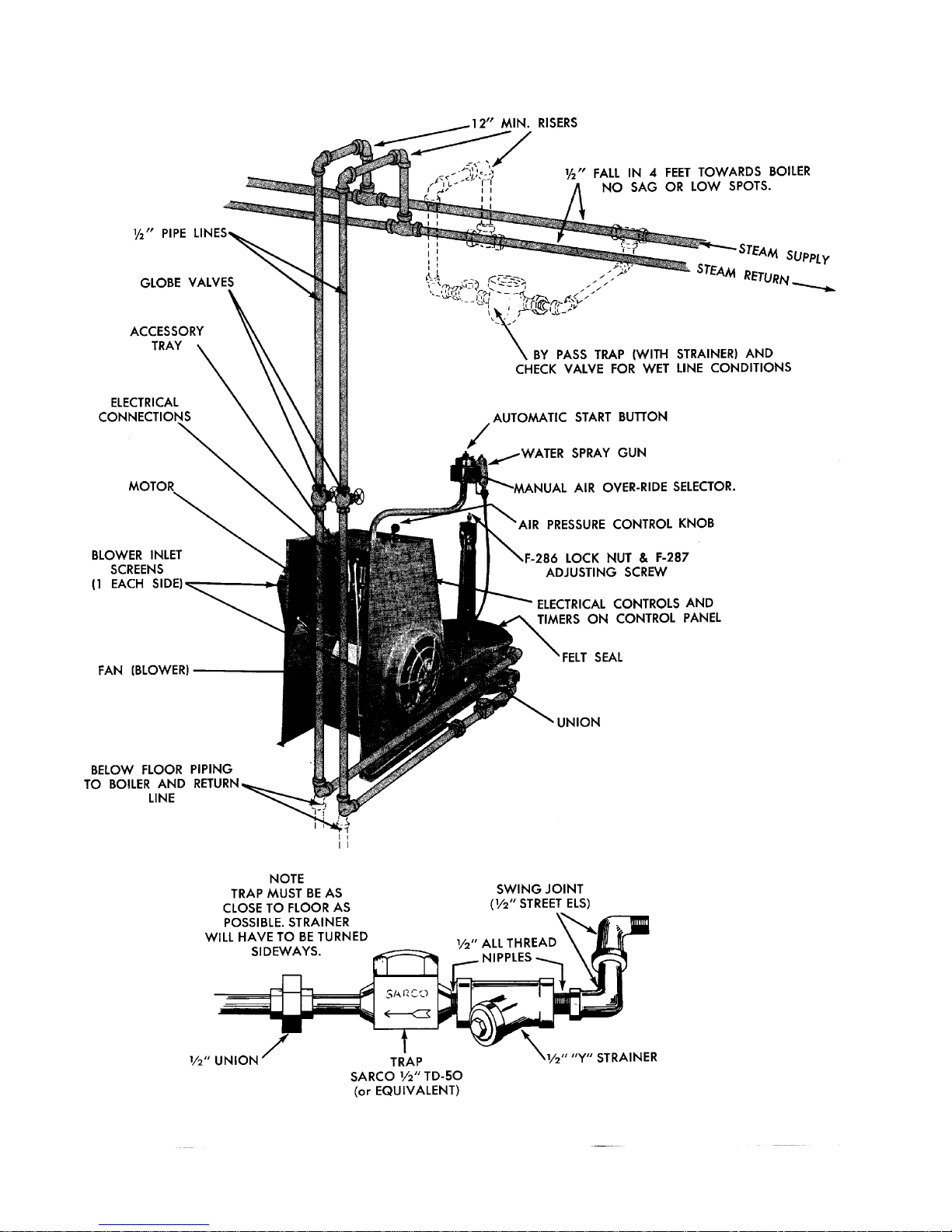
INSTALLATION INSTRUCTIONS (REFER TO ILLUSTRATION SHEET)
UNCRATE MACHINE. Check voltage and current on name plate before installing
machine. Electrical specification of relays, timers and motor solenoids must be the
same. Do not remove the plastic protective cover on the form until the machine is
ready to be placed in operation.
SET MACHINE IN POSITION. Grip a control knob and the turning knob and lift
revolving form assembly about 22” to remove from base.
CONNECT STEAM SUPPLY LINE. This line must fall towards the macnine (without
water pockets). Connect to steam supply line with union, gate valve and 12” or more
riser. If finisher is located near end of steam line, install a by-pass trap and check
valve as illustrated in dotted lines.
CONNECT RETURN LINE. This line must fall towards boiler (without water pockets).
Connect to steam return line with unions, strainer, steam trap, and 12” or more riser.
Inspect trap carefully for inlet and outlet markings. Install trap as near the machine
as possible, and lower than the return line outlet on the machine.
TIONTION
TION
TIONTION
NOTE: A check valve is not required for a thermodynamic trap. A check
valve is required with an impulse trap.
Use a Sarco or Yarway Thermo-dynamic Trap, Impulse trap or
equal in the return line of the machine. Do not use a bucket
trap unless its size will permit installation below the return line
outlet of the machine.
IMPORTANT: Before making final connection to return line, open gate valve in steam
supply line and flush pipe dope, borings, and all other foreign matter from the steam
connections and steam chamber. Failure to do so will cause trap troubles.
Page 5Page 5
Page 5
Page 5Page 5
Page 6Page 6
Page 6
Page 6Page 6

MAKE ELECTRICAL CONNECTIONS. Refer to wiring diagram on fan housing inside the
control panel. All controls and motors are single phase. The line voltage must be the same
as the electrical specifications of the motor and controls. Electrical connections must include a fused disconnect switch and be capable of carrying 15 amps, 115 volts or 8 amps,
230 volts. Use only “slo-blow” fuses. UL and California Codes require 2 black wires for 220
volt, 1 black, 1 white for 110 volt: The white is the grounded 115 volt neutral of a 3-wire
220 volt system. Connect the two black leads of a 115 volt machine to the proper terminals
of the electrical power line. Connect the green lead to an approved ground.
To connect standard single-phase machines to 3 phase current, be sure the voltage is cor rect, then connect the two black power leads to any two terminals of the 3 phase line
through an approved disconnect switch.
NOTE! Consult your local electrical code before making any electrical
connections, and be sure that the electrical installation conforms with
all local requirements. Double c hec k all wiring connections before
closing disconnect switch.
Replace revolving form on the base. Remove plastic protective cover
and all packing paper and tags from the form and clamps.
TEST THE MACHINE. Turn main disconnect “ON” and machine Fan Motor Selector
switch “ON”. The blower motor will start and run continuously. Move air pressure lever to
MAX air position and operate Air Selector on push button box. Air will inflate the bag and
permit it to deflate as the selector is moved “ON” and “OFF”. Turn the selector to “OFF”.
Set the Steam Timer to approximately three seconds and the Air-Timer to approximately 8
seconds.
Turn the Steam-Air Selector to “SEPARATE”. Push START button or Foot Pedal momentarily. The machine will “steam” for 3 seconds and blow air for 8 seconds. (The steam
solenoid will operate but no steam will escape since the steam is turned off).
Turn the Steam-Air Selector to “MIXED”. Push START button or Foot Pedal momentarily.
The machine will “steam” and air will blow simultaneously. At the end of 3 seconds the
steam solenoid will release. At the end of 8 seconds the air solenoid will release and the
bag will deflate.
Repeat each cycle several times.
YOUR CISSELL FORM IS READY TO OPERATE.
GENERAL NOTES: When machine is not in use, permit it to cool, and replace the plastic
protective cover on the form to prevent dust and dirt from soiling the nylon.
Remove nylon bag from the machine (see detailed illustration) at frequent intervals for
cleaning, as determined by its soiled condition. WET cleam only - do NOT dryclean. After
wet cleaning, the nylon bag should be extracted and blown dry on a garment dryer.
Page 7Page 7
Page 7
Page 7Page 7

Keep nylon bag clean. The nylon fabric acts as a filter in operation, collecting dust and
lint from the air, which clogs the fabric pores and greatly reduces its efficient operation.
Failure to keep bag clean may cause transfer of soil from bag to garments.
Repair holes or worn spots in nylon bag to extend its useful life. Reinforcement is
applied at points of greatest wear to extend the bags useful life. Replace when holes or
worn spots are beyond repair. A defective or badly worn nylon bag will cause the machine to operate unsatisfactorily.
CACA
UTIONUTION
CA
UTION
CACA
UTIONUTION
Use only genuine Cissell replacement nylon bags for satisfactory results. The fabric for
Cissell Nylon bags is especially woven (and cut to an exact pattern) to give the correct
porosities for proper operation, steaming and drying. Your Cissell Form depends entirely on the nylon bag for proper operation.
SPECIFICASPECIFICA
SPECIFICA
SPECIFICASPECIFICA
Electric Motor: 3/4 HP, 3450 RPM, 115/230 Volts, 60 Cycle, AC single phase
Operating Steam Pressure: 60 to 100 psig, recommended pressure 80-90 lbs.
Boiler Horsepower: Approximately 2
Steam Supply Line: 1/2” pipe
Steam Return Line: 1/2” pipe
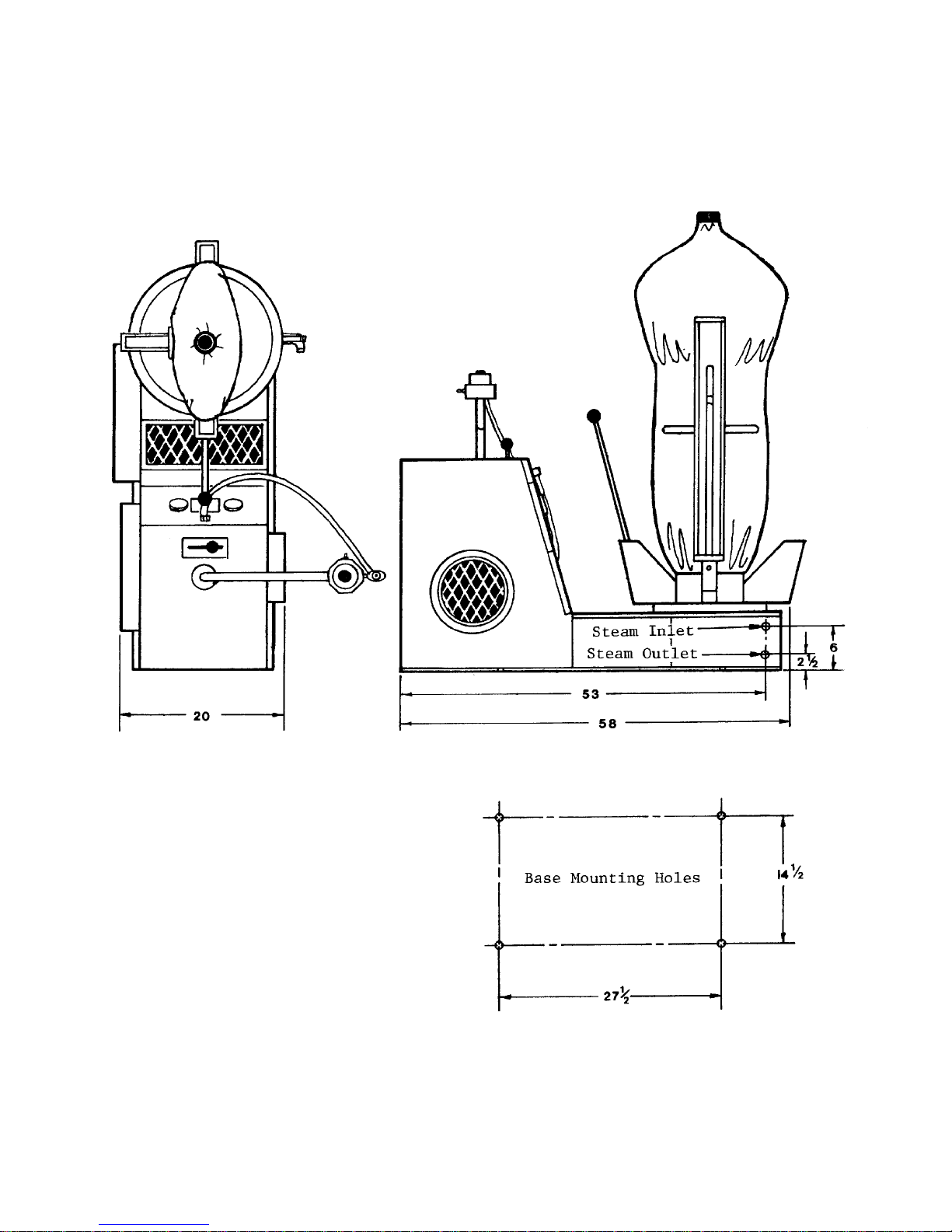
Depth: 44”
Height: 62” (Approx. depending on type of form)
Width: 19”
Swinging Radius: 22”
Net Weight: Approx. 220 lbs.
TIONSTIONS
TIONS
TIONSTIONS
Page 8Page 8
Page 8
Page 8Page 8

OPERAOPERA
OPERA
OPERAOPERA
CISSELL FMFC CISSELL FMFC
CISSELL FMFC
CISSELL FMFC CISSELL FMFC
STEAM TIMER - Set Timer for required cycle. Located on the control panel (front of the blower
housing). Turn the small knob on the timer face until the pointer indicates the desired time setting.
Turn the knob only when the machine is not in an automatic cycle.
FOR LIGHT SYNTHETIC FABRICS, a time setting of 3 to 4 seconds is normally adequate. For
heavier, more absorbant fabrics increase the time setting until a good finish is obtained.
NOTE: Avoid over-steaming. Over-steaming may shrink stitching, require a longer drying time,
cause condensation and slow production. The minimum steam that will give the desired finish is best.
1. AIR TIMER - Set Timer for required cycle. Located on the control panel (front of the blower
housing). Turn the small knob on the timer face until the pointer indicates the desired time setting.
Turn the knob only when the machine is not in an automatic cycle.
FOR LIGHT SYNTHETIC FABRICS, a time setting of 4 to 5 seconds with SEPARATE Steam-Air or
7 to 9 seconds with “”MIXED” Steam-Air is normally adequate. For heavier fabrics that retain more
moisture, increase the air time until the garment is properly cured.
2 SET PRESSURE CONTROL lever “A” at minimum position.
TING INSTRUCTIONS FORTING INSTRUCTIONS FOR
TING INSTRUCTIONS FOR
TING INSTRUCTIONS FORTING INSTRUCTIONS FOR
AND FMJC FORM FINISHERAND FMJC FORM FINISHER
AND FMJC FORM FINISHER
AND FMJC FORM FINISHERAND FMJC FORM FINISHER
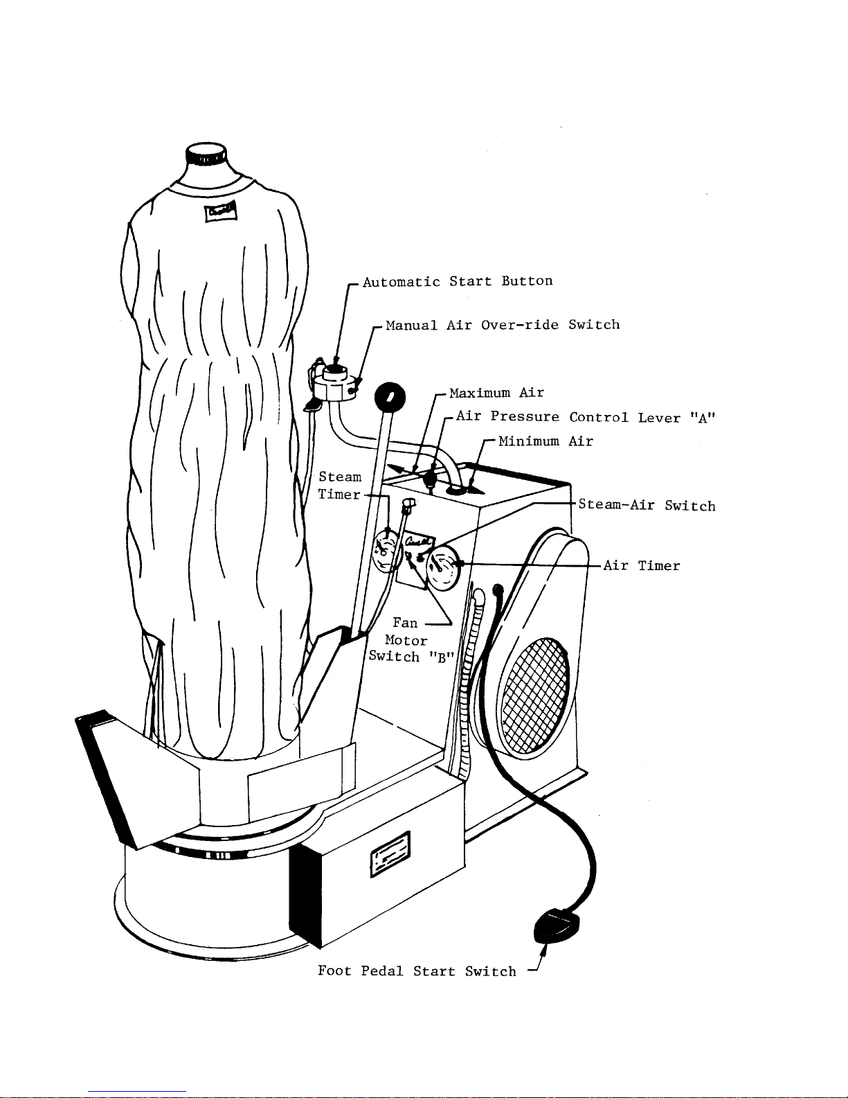
(See drawing on next page)
3 PUSH FAN MOTOR SWITCH to “ON” position. Located on the control panel (front of the blower
housing). Blower will start and run continuously and control circuits will be energized. Machine
can be operated automatically or manually. To de-energize the entire machine, push selector switch
to “OFF”.
4 POSITION GARMENT on form and adjust shoulders (knob on top of form).
5 PUSH MANUAL AIR OVERRIDE SWITCH to “ON” position. Located on the push button box.
When the Fan Motor switch is turned “ON” and the bag inflates and remains inflated, move the air
override selector to its opposite position.
6 PUSH PRESSURE CONTROL LEVER “A” toward maximum until bag comes within 1/4” of filling
hemline of garment.
7 RETURN MANUAL AIR OVERRIDE SWITCH to “OFF” position.
8 PRESS AUTOMATIC START BUTTON - Located on the movable pipe column supported on the
blower housing. This button or the FOOT PEDAL SWITCH is pressed momentarily to start the
automatic cycle. This can be operated from either side of machine. (by swinging column.)
9 REPEAT STEPS 2, 4, 6, 7 and 8 when changing size and/or styles.
10 STEAM AIR SWITCH - Located on the control panel (front of the blower housing). For automatic
sequence of STEAM WITHOUT AIR FOLLOWED BY AIR, push switch to “SEPARATE” position.
For automatic sequence of STEAM AND AIR MIXED (simultaneous start) followed by AIR ONLY,
push switch to “MIXED” position. Determine the best setting for each fabric by test. When using
STEAM AND AIR MIXED the air time should be doubled; Example -
Steam - Air - Total
4 sec. 8 sec. 8 sec.
Page 9Page 9
Page 9
Page 9Page 9
Page 10Page 10
Page 10
Page 10Page 10

MECHANICAL MECHANICAL
MECHANICAL
MECHANICAL MECHANICAL
AIR PRESSURE CONTROL - A control lever is provided just below the push button support column in the accessory tray. Move the lever to obtain the desired air pressure. In
general the air pressure ahould be sufficient to pull the garment taut without stretching it.
The lower pressures are generally used for wools and very fragile fabrics or fabrics that
tend to distort very easily and should not be pulled overly taut while they are curing.
ADJUSTABLE LEVERS - Move back and forth to regulate size of nylon bag at waist, hem
and lower positions. Rotate knob on lever c lockwise to loc k, counter-clockwise 1/4 to 1/2
turn to unlock. Move knob forward (toward form) to decrease size of bag and back (away
from form) to increase size of bag. Avoid excessive tightening or loosening of knobs as this
will require additional time and slow production. Adjust these levers with a garment on
the form and manual air turned on, with pressure set as indicated by the Garment Fabric.
WAIST CONTROL - Regulates expansion at waist line. Start with the Lever
completely forward. Unloc k the control knob and move back to the desired position.
Move the garment in the area of the waist while the bag is being enlarged. When
the bag barely makes the garment taut in the waist, lock the lever in position.
HEM CONTROL - Regulates expansion at hem line. Start with the Lever
completely forward. Unloc k the control knob and move back to the desired position.
Observe the garment at the hem line. When the bag pulls the hemline taut without
“belling”, lock the lever in position.
ADJUSTMENTSADJUSTMENTS
ADJUSTMENTS
ADJUSTMENTSADJUSTMENTS
LOWER CONTROL - Regulates amount of fullness in hip area and size of bag at
hem line. Start with the Lever completely forward. Unlock the control knob and
move back to the desired position. Observe the garment in the hip and waist area.
Enlarge the bag until the hip is full, but do NOT permit enough fullness to cause a
roll at the waist.
NOTE! Some sizes and styles of garments will require adjustment of hem
control again after the lower control is adjusted in order to obtain the
best possible overall adjustment.
SLEEVE CONTROLS - (Only on bags provided with nylon sleeves). Rings are provided on
the bag sleeves to adjust the effective sleeve length. Slide the rings up or down as required
until the garment sleeves are well filled but not “belled”. When the form sleeves are not
required, fasten ther sleeve ends together inside the bag with the ball-c hain and swivels
sewn into the sleeve ends. Sleeves may be left hanging loose if garment fabric does not
stretch or mark easily.
SHOULDER WIDTH ADJUSTMENT - A knob on top of the form is used to adjust the form
shoulder width to suit the garment. Turn knob clockwise to increase width - counter -clockwise to decrease.
Page 11Page 11
Page 11
Page 11Page 11

ELECTRICAL CONTROLSELECTRICAL CONTROLS
ELECTRICAL CONTROLS
ELECTRICAL CONTROLSELECTRICAL CONTROLS
FAN MOT OR SWITCH - Located on the control panel (front of the blower housing).
Push to “ON” position. Blower will start and run continuously and control circuits will
be emergized. Machine can be operated automatically or manually. To de-energize the
entire machine, push selector switch to “OFF”.
STEAM AIR SWITCH - Located on the control panel (front of the blower housing). For
automatic of steam without air followed by air, push switch to “SEPARATE” position.
For automatic sequence of steam and air mixed (simultaneous start) followed by air
only, push switch to “MIXED” position. Determine the best setting for each fabric by
test.
MANUAL AIR OVERRIDE SWITCH: Located on the push button box. When the
blower motor is running, push selector to one side to inflate the bag. Return it to its
other position to deflate the bag. When the Fan Motor switch is turned “ON” and the
bag inflates and remains inflated, move the air override selector to its opposite position.
AUTOMATIC START BUTTON - Located on the movable pipe column supported on
the blower housing. This button or the foot pedal may be used to start the automatic
cycle. Press either momentarily to start.
STEAM TIMER - Located on the control panel (front of the blower housing). Turn the
small knob on the timer face until the pointer indicates the desired time setting. Turn
the knob only when the machine is not in an automatic cycle.
For light synthetic fabrics a time setting of 3 to 4 seconds is normally adequate. For
heavier more absorbant fabrics increase the time setting until a good finish is obtained.
NOTE: Avoid over-steaming. Over-steaming may shrink stitching, require
a longer drying time, cause condensation and slow production. The
minimum steam that will give the desired finish is best.
AIR TIMER - Located on the control panel (front of the blower housing). Turn the
small knob on the timer face until the pointer indicates the desired time setting. Turn
the knob only when the machine is not in an automatic cycle.
For light synthetic fabrics a time setting of 4 to 5 seconds with “SEPARATE” Steam-Air
or 7 to 9 seconds with “MIXED” Steam-Air is normally adequate. For heavier fabrics
that retain more moisture, increase the air time until the garment is properly cured.
Page 12Page 12
Page 12
Page 12Page 12
 Loading...