

Cissell MAN78, FP, FL, QP, MP User Manual
...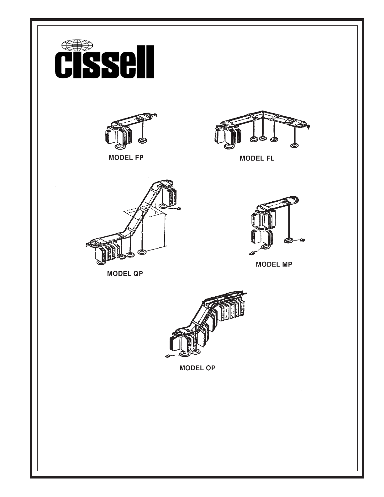
Conveyors
CISSELL MANUFACTURING COMPANY
HEADQUARTERS PHONE: (502) 587-1292
831 SOUTH FIRST ST. SALES FAX: (502) 585-3625
P.O. BOX 32270 SERVICE/PARTS FAX: (502) 681-1275
LOUISVILLE, KY 40232-2270
THIS MANUAL MUST BE GIVEN TO THE EQUIPMENT OWNER.
MAN78 8/96
Page 1
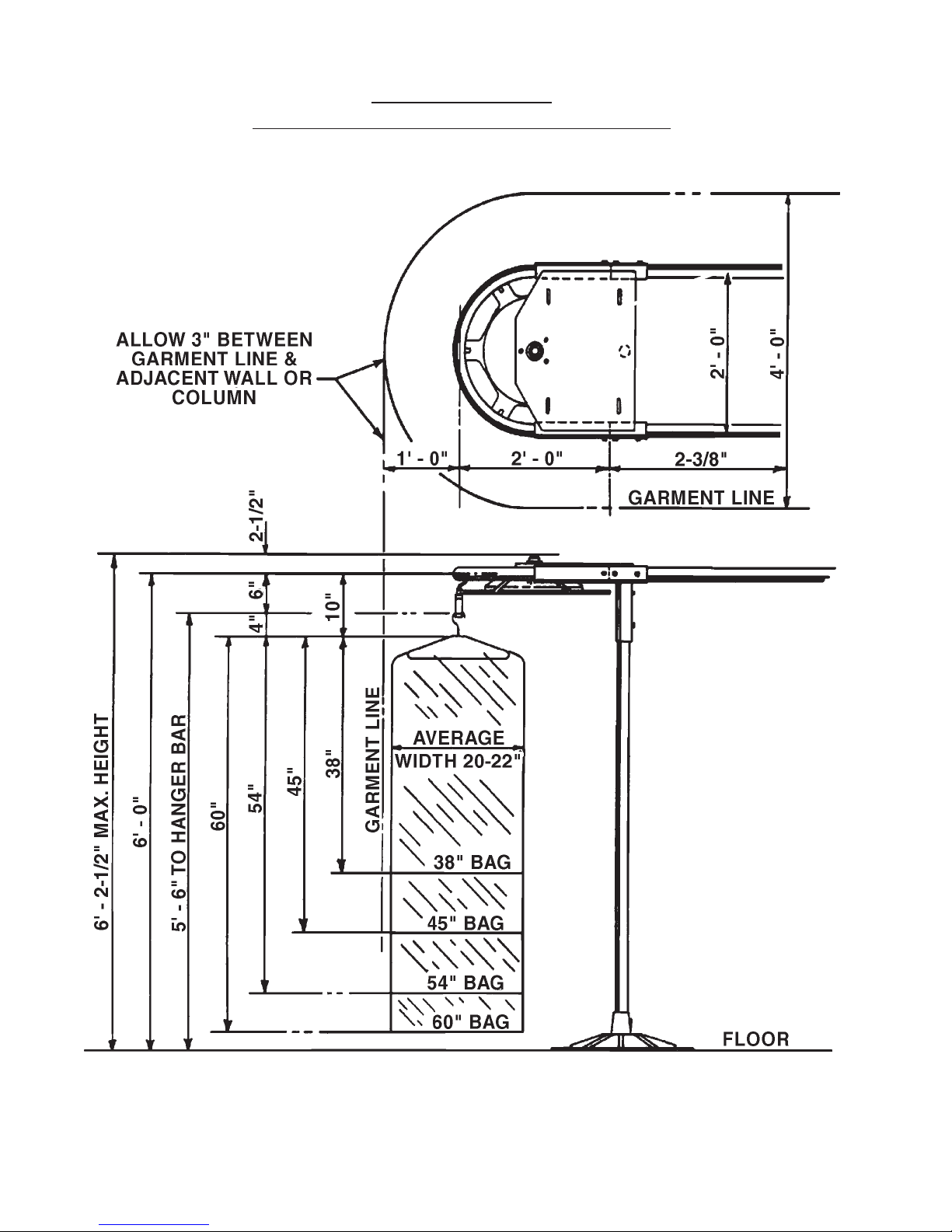
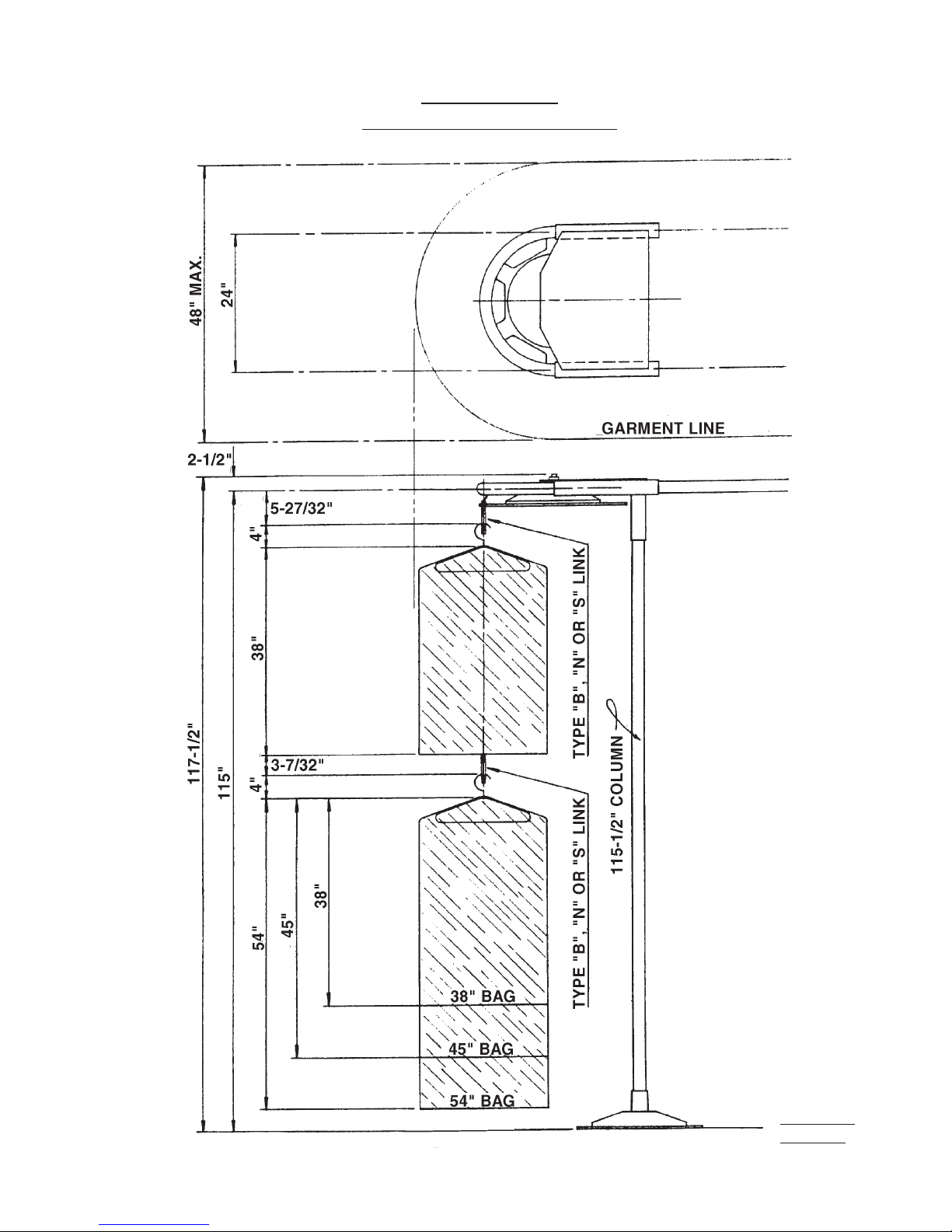
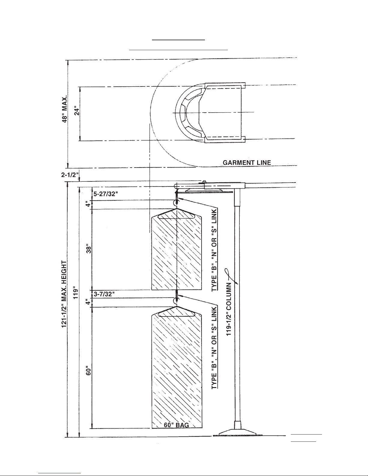
GARMENT BAG
DIMENSIONS AND CLEARANCE (60)
Page 2
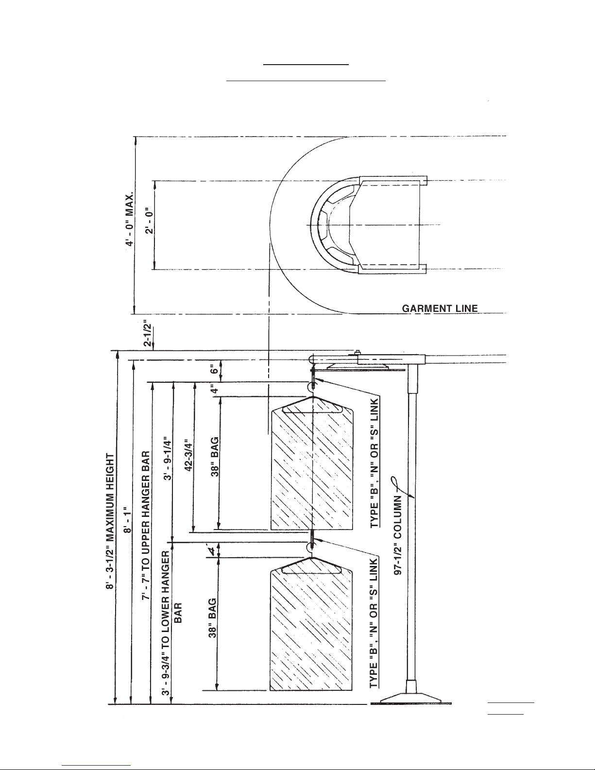
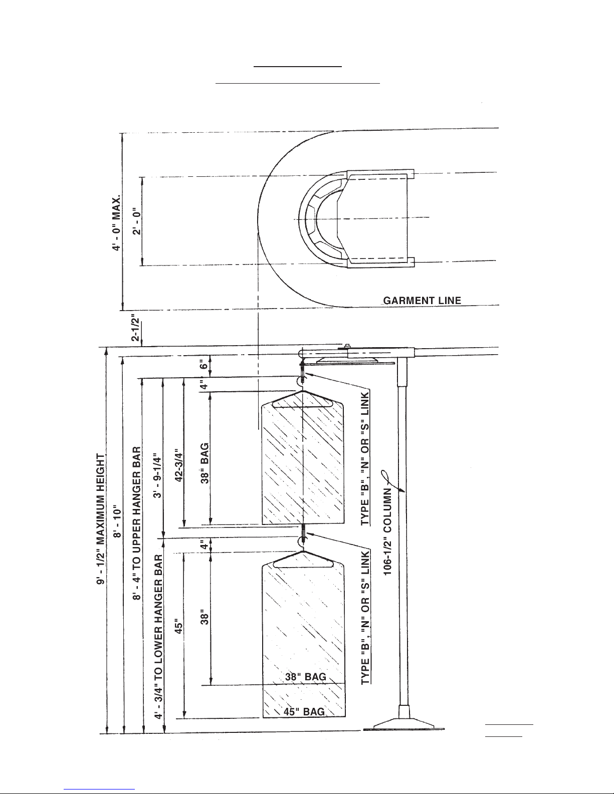
CONVEYOR
DOUBLE DECK (38/38)
1-29-69-NS
1-5327-6
Page 3
CONVEYOR
DOUBLE DECK (38/45)
1-30-69-NS
1-5327-9
Page 4
CONVEYOR
DOUBLE DECK (38/54)
1-31-69-NS
1-5327-10
Page 5
CONVEYOR
DOUBLE DECK (38/60)
1-31-69-NS
1-5327-10
Page 6
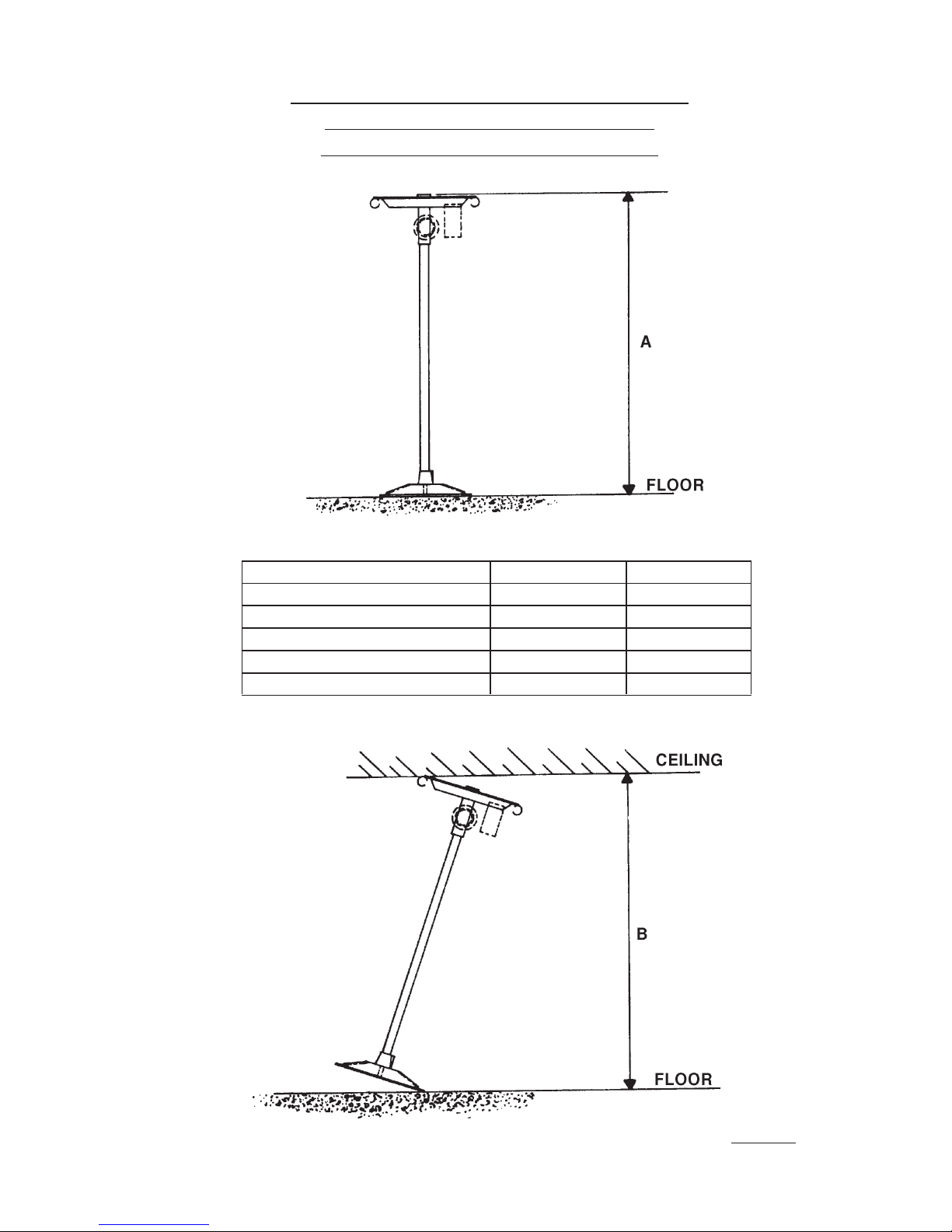
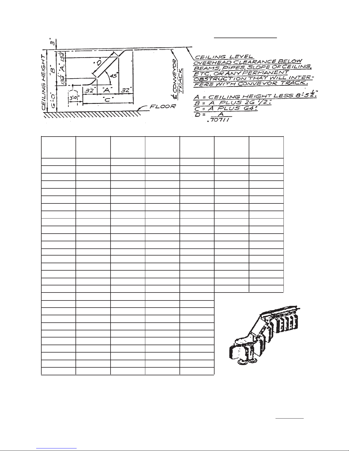
MINUMUM CEILING HEIGHT FOR
INSTALLATION OF CISSELL
FLOOR MODEL CONVEYORS
TYPE A B
FLOOR MODEL 6’ - 2-1/2” 6’ - 5”
DOUBLE DECK 38” BAG 7’ - 15-1/2” 8’ - 6”
DOUBLE DECK 45” BAG 9’ - 1/2” 9’ - 3”
DOUBLE DECK 54” BAG 9’ - 9-1/2” 10’ - 1/2”
DOUBLE DECK 60” BAG 10’ - 1-1/2” 10’ - 4”
1-5327-11
Page 7
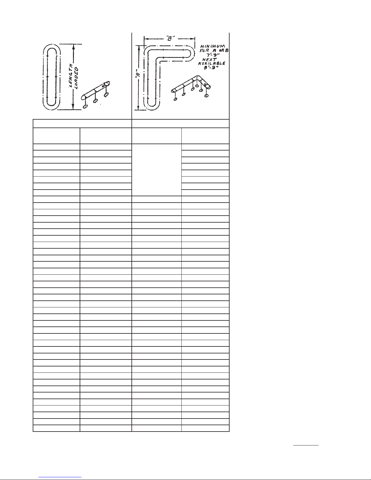
STRAIGHT FLOOR MODEL “L” FLOOR MODEL
NO. CONVEYOR
OF LENGTH
LINKS LOADED
14 8’-0” 5 8 30’-0” 58 34’-6”
15 8’-6” 5 9 30’-6” 59 35’-0”
16 9’-0” 6 0 31’-0” 60 35’-6”
17 9’-6” 6 1 31’-6” 61 36’-0”
18 10’-0” 62 32’-0” 62 36’-6”
19 10’-6” 63 32’-6” 63 37’-0”
20 11’-0” 64 33’-0” 64 37’-6”
21 11’-6” 65 33’-6” 65 38’-0”
22 12’-0” 66 34’-0” 22 16’-6” 66 38’-6”
23 12’-6” 67 34’-6” 23 17’-0” 67 39’-0”
24 13’-0” 68 35’-0” 24 17’-6” 68 39’-6”
25 13’-6” 69 35’-6” 25 18’-0” 69 40’-0”
26 14’-0” 70 36’-0” 26 18’-6” 70 40’-6”
27 14’-6” 71 36’-6” 27 19’-0” 71 41’-0”
28 15’-0” 72 37’-0” 28 19’-6” 72 41’-6”
29 15’-6” 73 37’-6” 29 20’-0” 73 42’-0”
30 16’-0” 74 38’-0” 30 20’-6” 74 42’-6”
31 16’-6” 75 38’-6” 31 21’-0” 75 43’-0”
32 17’-0” 76 39’-0” 32 21’-6” 76 43’-6”
33 17’-6” 77 39’-6” 33 22’-0” 77 44’-0”
34 18’-0” 78 40’-0” 34 22’-6” 78 44’-6”
35 18’-6” 79 40’-6” 35 23’-0” 79 45’-0”
36 19’-0” 80 41’-0” 36 23’-6” 80 45’-6”
37 19’-6” 81 41’-6” 37 24’-0” 81 46’-0”
38 20’-0” 82 42’-0” 38 24’-6” 82 46’-6”
39 20’-6” 83 42’-6” 39 25’-0” 83 47’-0”
40 21’-0” 84 43’-0” 40 25’-6” 84 47’-6”
41 21’-6” 85 43’-6” 41 26’-0” 85 48’-0”
42 22’-0” 86 44’-0” 42 26’-6” 86 48’-6”
43 22’-6” 87 44’-6” 43 27’-0” 87 49’-0”
44 23’-0” 88 45’-0” 44 27’-6” 88 49’-6”
45 23’-6” 89 45’-6” 45 28’-0” 89 50’-0”
46 24’-0” 90 46’-0” 46 28’-6” 90 50’-6”
47 24’-6” 91 46’-6” 47 29’-0” 91 51’-0”
48 25’-0” 92 47’-0” 48 29’-6” 92 51’-6”
49 25’-6” 93 47’-6” 49 30’-0” 93 52’-0”
50 26’-0” 94 48’-0” 50 30’-6” 94 52’-6”
51 26’-6” 95 48’-6” 51 31’-0” 95 53’-0”
52 27’-0” 96 49’-0” 52 31’-6” 96 53’-6”
53 27’-6” 97 49’-6” 53 32’-0” 97 54’-0”
54 28’-0” 98 50’-0” 54 32’-6” 98 54’-6”
55 28’-6” 99 50’-6” 55 33’-0” 99 55’-0”
56 29’-0” 100 51’-0” 56 33’-6” 100 55’-6”
57 29’-6” 57 34’-0”
NO. CONVEYOR
OF LENGTH
LINKS LOADED
NO. CONVEYOR
O F A & B
LINKS LOADED
NO. CONVEYOR
O F A & B
LINKS LOADED
CISSELL
CONVEYORS
1-5025-36
Page 8
UP AND DOWN
CISSELL CONVEYOR
CEILING MINIMUM MINIMUM
HEIGHT
10’-0” 1’-6 1/2” 3’-9” 6’-10 1/2” 2’-2 1/8” 14’-2 3/8” 29
10’-3” 1’-9 1/2” 4’-0” 7’-1 1/2” 2’-6 3/8” 14’-7 1/8” 30
10’-6” 2’-0 1/2” 4’-3” 7’-4 1/2” 2’-10 5/8” 14’-5 7/8” 30
10’-9” 2’-3 1/2” 4’-6” 7’-7 1/2” 3’-2 7/8” 14’-10 5/8” 31
11’-0” 2’-6 1/2” 4’-9” 7’-10 1/2” 3’-7 1/8” 15’-3 3/8” 32
11’-3” 2’-9 1/2” 5’-0” 8’-1 1/2” 3’-11 3/8” 15’-2 1/8” 32
11’-6” 3’-0 1/2” 5’-3” 8’-4 1/2” 4’-3 5/8” 15’-6 7/8” 33
11’-9” 3’-3 1/2” 5’-6” 8’-7 1/2” 4’-7 7/8” 15’-11 5/8” 34
12’-0” 3’-6 1/2” 5’-9” 8’-10 1/2” 5’-0” 14’-10 1/2” 32
12’-3” 3’-9 1/2” 6’-0” 9’-1 1/2” 5’-4 3/8” 16’-3 1/8” 35
12’-6” 4’-0 1/2” 6’-3” 9’-4 1/2” 5’-8 5/8” 16’-7 7/8” 36
12’-9” 4’-3 1/2” 6’-6” 9’-7 1/2” 6’-0 7/8” 17’-0 5/8” 37
13’-0” 4’-6 1/2” 6’-9” 9’-10 1/2” 6’-5 1/8” 16’-11 3/8” 37
13’-3” 4’-9 1/2” 7’-0” 10’-1 1/2” 6’-9 3/8” 17’-4 1/8” 38
13’-6” 5’-0 1/2” 7’-3” 10’-4 1/2” 7’-1 1/2” 17’-9” 39
13’-9” 5’-3 1/2” 7’-6” 10’-7 1/2” 7’-5 3/4” 17’-7 3/4” 39
14’-0” 5’-6 1/2” 7’-9” 10’-10 1/2” 7’-10” 18’-0 1/2” 40
14’-3” 5’-9 1/2” 8’-0” 11’-1 1/2” 8’-2 1/4” 18’-5 1/4” 41
14’-6” 6’-0 1/2” 8’-3” 11’-4 1/2” 8’-6 1/2”
14’-9” 6’-3 1/2” 8’-6” 11’-7 1/2” 8’-10 3/4”
15’-0” 6’-6 1/2” 8’-9” 11’-10 1/2” 9’-3”
15’-3” 6’-9 1/2” 9’-0” 12’-1 1/2” 9’-7 1/4”
15’-6” 7’-0 1/2” 9’-3” 12’-4 1/2” 9’-11 1/2”
15’-9” 7’-3 1/2” 9’-6” 12’-7 1/2” 10’-3 3/4”
16’-0” 7’-6 1/2” 9’-9” 12’-10 1/2” 10-8”
16’-3” 7’-9 1/2” 10’-0” 13’-1 1/2” 11’-0 1/4”
16’-6” 8’-0 1/2” 10’-3” 13’-4 1/2” 11’-4 1/2”
16’-9” 8’-3 1/2” 10’-6” 13’-7 1/2” 11’-8 3/4”
17’-0” 8’-6 1/2” 10’-9” 13’-10 1/2” 12’-1”
“A” “B” “C” “D” OVER LINKS
GARMENTS
8-2-72
TWO OR THREE SUPPORTS TO FLOOR
AT LOWER END AND OVERHEAD
CHANNELS WITH STRAPS FURNISHED
WITH CONVEYOR. NO SUPPORTS TO
FLOOR UNDER UPPER SECTION.
1-5025-21A
Page 9
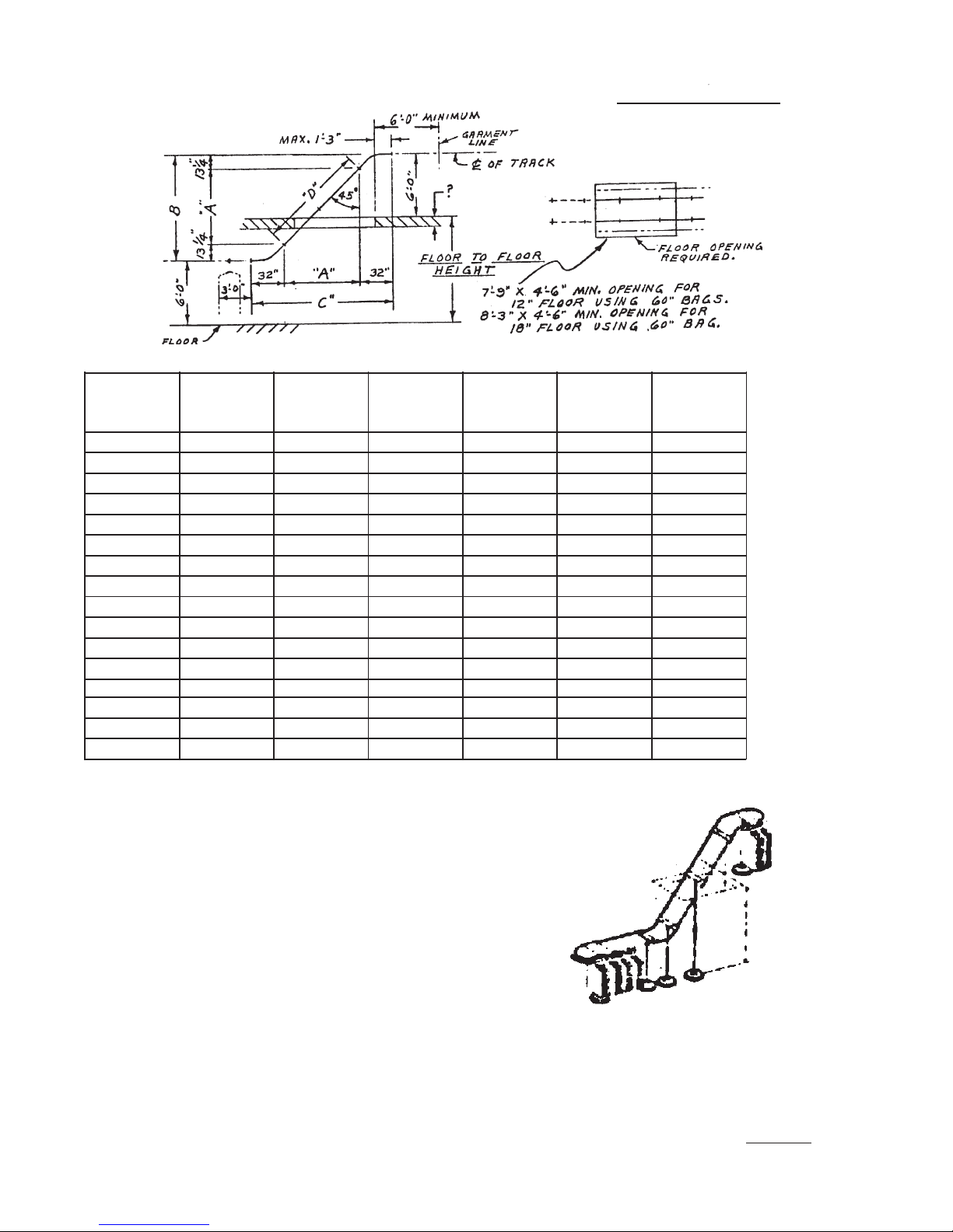
DESCENDING
CISSELL CONVEYOR
CEILING MINIMUM MINIMUM
HEIGHT
7’-3” 5’-0 1/2” 7’-3” 10’-4 1/2” 7’-1 1/2” 17’-9” 39
7’-6” 5’-3 1/2” 7’-6” 10’-7 1/2” 7’-5 3/4” 17’-7 3/4” 39
7’-9” 5’-6 1/2” 7’-9” 10’-10 1/2” 7’-10” 18’-0 1/2” 40
8’-0” 5’-9 1/2” 8’-0” 11’-1 1/2” 8’-2 1/4” 18’-5 1/4” 41
8’-3” 6’-0 1/2” 8’-3” 11’-4 1/2” 8’-6 1/2” 18’-10” 42
8’-6” 6’-3 1/2” 8’-6” 11’-7 1/2” 8’-10 3/4” 18’-8 3/4” 42
8’-9” 6’-6 1/2” 8’-9” 11’-10 1/2” 9’-3” 19’-1 1/2” 43
9’-0” 6’-9 1/2” 9’-0” 12’-1 1/2” 9’-7 1/4” 19’-6 1/4” 44
9’-3” 7’-0 1/2” 9’-3” 12’-4 1/2” 9’-11 1/2” 19’-5” 44
9’-6” 7’-3 1/2” 9’-6” 12’-7 1/2” 10’-3 3/4” 19’-9 3/4” 45
9’-9” 7’-6 1/2” 9’-9” 12’-10 1/2” 10’-8” 20’-2 1/2” 46
10’-0” 7’-9 1/2” 10’-0” 13’-1 1/2” 10’-0 1/4” 20’-7 1/4” 47
10’-3” 8’-0 1/2” 10’-3” 13’-4 1/2” 11’-4 1/2” 20’-6” 47
10’-6” 8’-3 1/2” 10’-6” 13’-7 1/2” 11’-8 3/4” 20’-10 3/4” 48
10’-9” 8’-6 1/2” 10’-9” 13’-10 1/2” 12’-1” 21’-3 1/2” 49
11’-0” 8’-9 1/2” 11’-0” 14’-1 1/2” 12’-5 1/4” 21’-2 1/4” 49
“A” “B” “C” “D” OVER LINKS
GARMENTS
ALL SUPPORTS TO FLOORS FURNISHED WITH
CONVEYOR. CUSTOMER TO BRACE TO RIGID
PART OF BUILDING IF REQ’D.
8-2-72
1-5025-35
Page 10
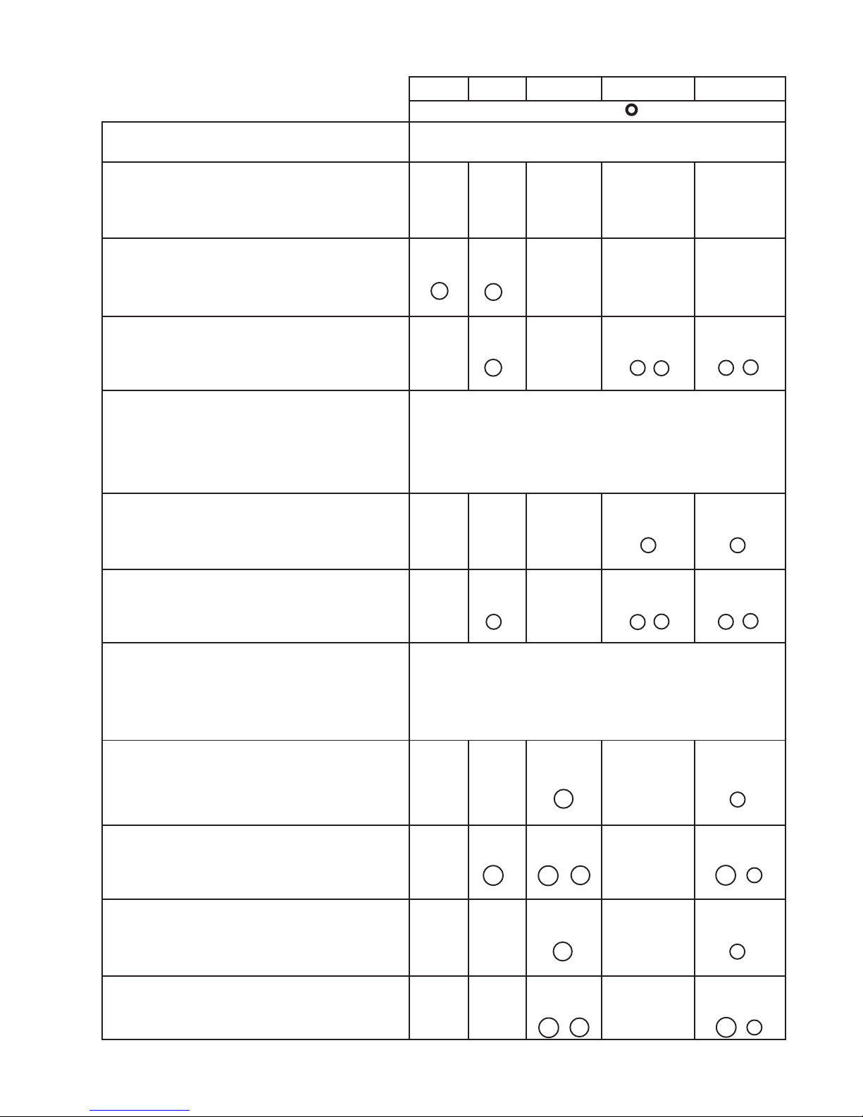
1/4 HP 1/2 HP 3/4 HP 1/4 + 1/4 HP 1/2 + 1/2 HP
No’s Are For Links Are For Adder No’s.
Floor Model “F” Conveyor
“P” Plain (Straight) 14-70 71-100 102-150 152-200
“L” Ell Shape 22-50 51-70
12
“L” Ell Shape w/Idlers 71-100 102-150 152-200
3 3 + 7 3 + 8
Double Deck “M” (No’s. Are For
Links Both Decks) Conveyor
“P” Plain (Straight) 202-300 302-400
30-200 7 8
“L” Ell Shape w/Idlers 50-200 202-300 302-400
3 3 + 7 3 + 8
Up & Down “O” or Descending
“Q” Conveyor
“P” Plain (Straight) 29-100 102-120 122-200
21 8
“L” Ell Shape w/Idlers 39-80 81-100 102-180
3A 3A + 21 3A + 8
“P” Plain (Straight) 41-100 102-150
“L” Ell Shape w/Idlers 51-80 81-150
21 8
3A + 21 3A + 8
Page 11

CONVEYOR
TRACK LUBRICATION
Put vaseline (or light grease) in bottom of roller track to lubricate
path of rollers. Also apply lubricant to top of tract at all curves.
A narrow strip of lubrication, about 1/8” in diameter and placed along
the center of the roller path for about 1 foot at 5 foot spacings, will be
picked up and spread by the rollers.
Do not apply lubricant beyond path of rollers as this will serve no
useful purpose.
Repeat every six months or when track surface becomes dry.
A properly lubricated track will provide quiet roller operation and
greatly extend the operating life.
Page 12
 Loading...