

Cissell FINTUNMAN67 User Manual

WARRANTY
The Cissell Manufacturing Company (Cissell) warrants all new equipment (and the original parts thereof)
to be free from defects in material or workmanship for a period of one (1) year from the date of sale thereof
to an original purchaser for use, except as hereinafter provided. With respect to non-durable parts normally
requiring replacement in less than one (1) year due to normal wear and tear, including, but not limited to,
cloth goods, valve discs, hoses, and iron cords, and with respect to all new repair or replacement parts for
Cissell equipment for which the one (1) year warranty period has expired, or for all new repair or
replacement parts for equipment other than Cissell equipment, the warranty period is limited to ninety (90)
days from date of sale. The warranty period on each new replacement part furnished by Cissell in fulfillment
of the warranty on new equipment or parts shall be for the unexpired portion of the original warranty period
on the part replaced.
With respect to electric motors, coin meters and other accessories furnished with the new equipment, but
not manufactured by Cissell, the warranty is limited to that provided by the respective manufacturer.
Cissell's total liability arising out of the manufacture and sale of new equipment and parts, whether under
the warranty or caused by Cissell's negligence or otherwise, shall be limited to Cissell repairing or replacing,
at its option, any defective equipment or part returned f.o.b. Cissell's factory, transportation prepaid, within
the applicable warranty period and found by Cissell to have been defective, and in no event shall Cissell be
liable for damages of any kind, whether for any injury to persons or property or for any special or
consequential damages. The liability of Cissell does not include furnishing (or paying for) any labor such
as that required to service, remove or install; to diagnose troubles; to adjust, remove or replace defective
equipment or a part; nor does it include any responsibility for transportation expense which is involved
therein.
The warranty of Cissell is contingent upon installation and use of its equipment under normal operating
conditions. The warranty is void on equipment or parts; that have been subjected to misuse, accident, or
negligent damage; operated under loads, pressures, speeds, electrical connections, plumbing, or conditions
other than those specified by Cissell; operated or repaired with other than genuine Cissell replacement
parts; damaged by fire, flood, vandalism, or such other causes beyond the control of Cissell; altered or
repaired in any way that effects the reliability or detracts from its performance, or; which have had the
identification plate, or serial number, altered, defaced, or removed.
No defective equipment or part may be returned to Cissell for repair or replacement without prior written
authorization from Cissell. Charges for unauthorized repairs will not be accepted or paid by Cissell.
CISSELL MAKES NO OTHER EXPRESS OR IMPLIED WARRANTY, STATUTORY OR OTHERWISE,
CONCERNING THE EQUIPMENT OR PARTS INCLUDING, WITHOUT LIMITATION, A WARRANTY
OF FITNESS FOR A PARTICULAR PURPOSE, OR A WARRANTY OF MERCHANTABILITY. THE
WARRANTIES GIVEN ABOVE ARE EXPRESSLY IN LIEU OF ALL OTHER WARRANTIES, EXPRESS
OR IMPLIED. CISSELL NEITHER ASSUMES, NOR AUTHORIZES ANY PERSON TO ASSUME FOR IT,
ANY OTHER WARRANTY OR LIABILITY IN CONNECTION WITH THE MANUFACTURE, USE OR SALE
OF ITS EQUIPMENT OR PARTS.
For warranty service, contact the Distributor from whom the Cissell equipment or part was purchased. If
the Distributor cannot be reached, contact Cissell.
Page 1

TABLE OF CONTENTS
GENERAL INFORMATION PAGE
Warranty ........................................................................................................................... 1
Outline Drawing.............................................................................................................. 3
INSTALLATION AND ADJUSTMENTS
Installation Power Struts.............................................................................................. 4
Steam Piping Installation ........................................................................................... 5-6
Spray Gun Hose Connections....................................................................................... 7
Conveyor Interlock and Door Adjustment................................................................. 9
Conveyor Link Installation.......................................................................................... 10
Door Interlock Switch Adjustment............................................................................. 11
Installation of Switch of Foot Pedal........................................................................... 1 2
Disassembling Tunnel................................................................................................... 1 3
OPERATION
Control Panel Operation............................................................................................... 14
Tunnel Operation Instructions.................................................................................... 15
TROUBLE SHOOTING CHARTS ...................................................................... 16-17
ILLUSTRATED PARTS
Conveyor Struts........................................................................................................... 18-19
Jacket Assembly ............................................................................................................. 20
Blower Assembly............................................................................................................. 2 1
Door Actuator Parts .................................................................................................... 22-23
Dual Spray Gun and Hose ........................................................................................... 2 5
Control Panel .................................................................................................................. 26
Drop Off Assembly ......................................................................................................... 2 7
Electrical Wiring Diagram........................................................................................... 28
Foot Switch and Junction Boxes................................................................................. 29
Conveyor Drive End ................................................................................................... 30-31
Steam Coil and Piping - 50 Hz................................................................................. 32-33
Steam Coil and Piping - 60 Hz................................................................................. 34-35
Mixing Jet Assembly...................................................................................................... 3 6
Water Spray Gun - Overhead Type ............................................................................ 3 7
Conveyor Links............................................................................................................... 38
Electrical Control Schematic ....................................................................................... 3 9
Wiring Diagrams ......................................................................................................... 40-41
Page 2
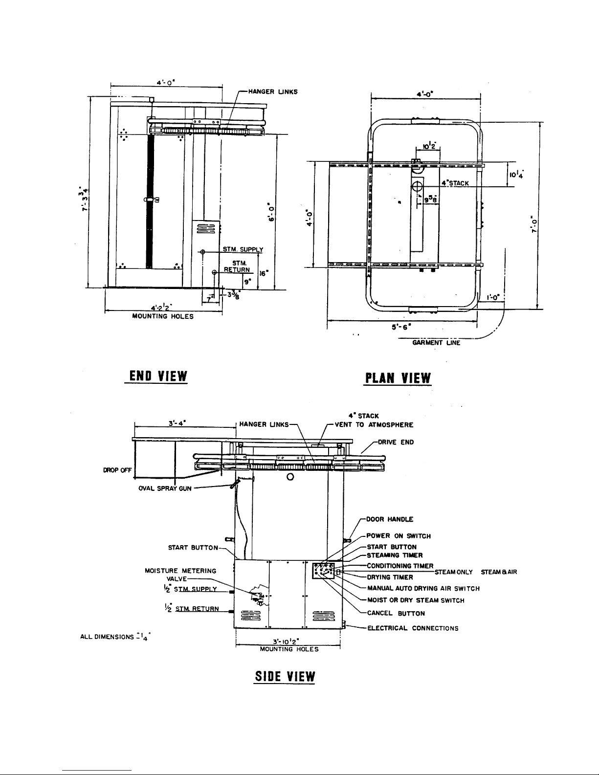
Page 3
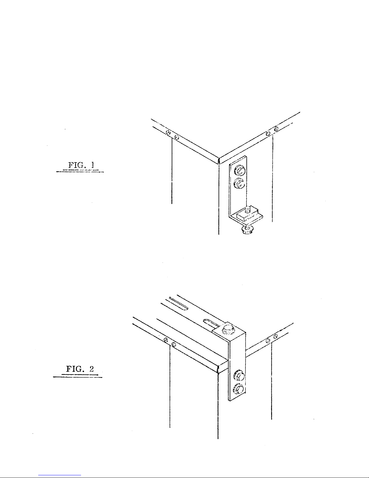
REAR POWER STRUT BRACKETS ARE MOUNTED UPSIDE DOWN FOR
SHIPPING PURPOSES. FIG. 1
WHEN INSTALLING POWER STRUTS, BE SURE TO INSTALL REAR BRACKETS
AS ILLUSTRATED IN FIG. 2.
Page 4

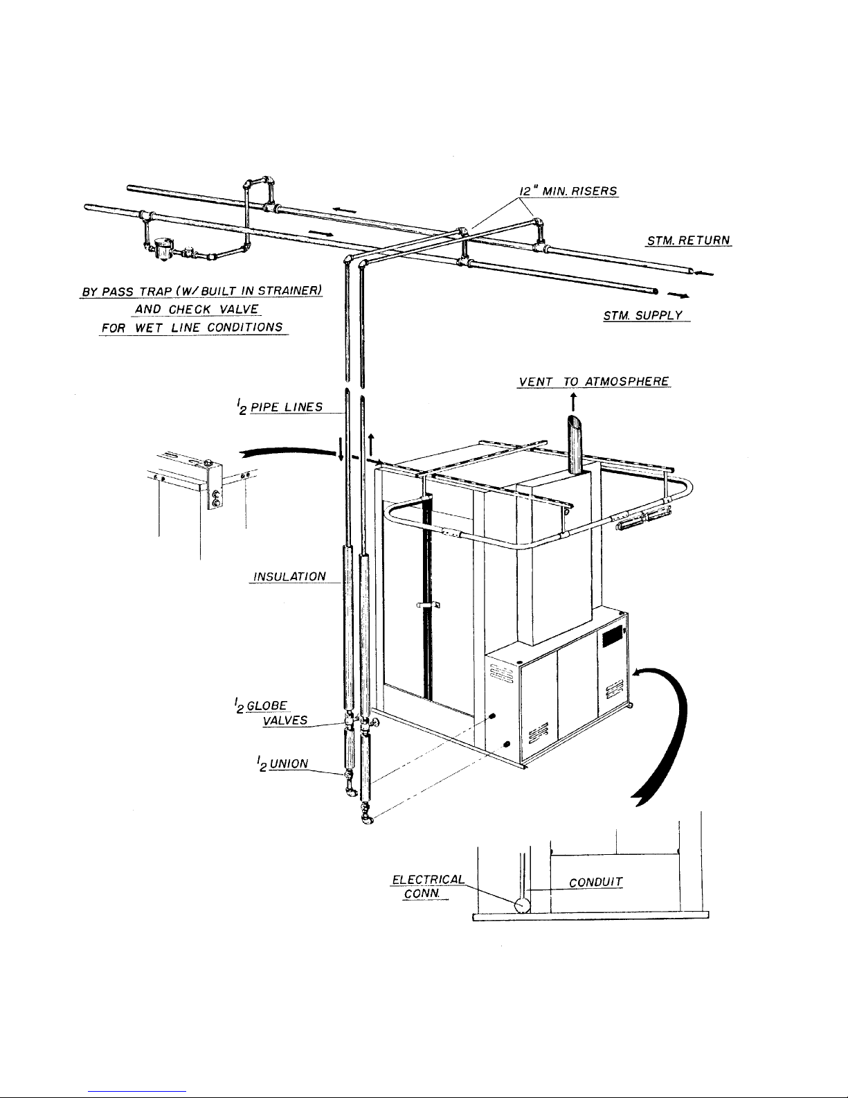
STEAM PIPING INSTALLATION INSTRUCTIONS
Refer to illustration on next page
IMPORTANT: INSTALL STEAM PIPING IN ACCORDANCE WITH
ALL LOCAL REGULATIONS AND REQUIREMENTS
1. Set and anchor Tunnel in position. Machine should be level to assure proper steam
circulation.
2. To prevent condensate draining from headers to Tunnel, piping should have a
minimum riser 12 above each respective header as illustrated. Do not make steam
connection to header with a horizontal or downwardly facing tee or elbow.
3. Whenever possible, horizontal runs of steam lines must drain, by gravity, to
respective steam header. Water pockets, or an improperly drained steam header
will provide wetsteam, causing improper operation of Tunnel. If pockets or
improper drainage cannot beeliminated, install a by-pass trap to drain condensate
from the low point in the steam supply header to the return.
4. In both the steam supply and steam return line, it is recommended that each have a
1/2 union and 1/2 globe valve. This will enable you to disconnect the steam
connections and service the Tunnel while your plant is in operation.
5. When Tunnel is on the end of a line of equipment extend headers at least 4 ft.
beyond Tunnel. Install globe valve, union, check valve and by-pass trap at end of
line. If gravity return to boiler, omit trap.
6. Insulate steam supply and return line for safety of operator and safety while
servicing Tunnel.
7. Keep Tunnel in good working condition. Repair or replace any worn or defective
parts.
8. If steam is dirty, it may be advisable to install a filter or blow-down ahead of tunnel.
Maintenance
The interior of the tunnel will turn white as the protective zinc oxide coating forms.
Do not try to remove this coating.
Do remove lint, dust, and boiler compound or red rust which is entrained by the steam.
Touch-up scratches and chips in the paint.
A good car wax will extend life of the painted surface.
Page 5
Page 6
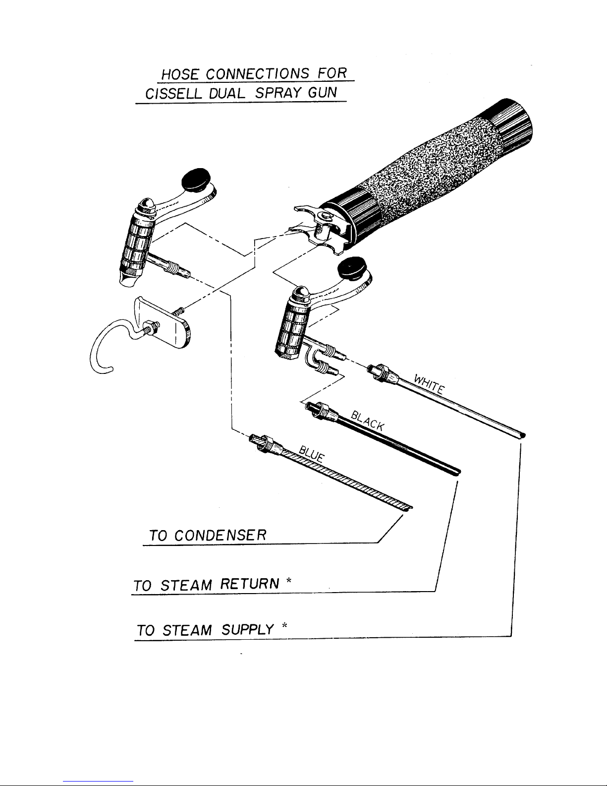
*
NOTE: This connection works best in most installations. Should there be excessive
condensate in the spray, reverse these two connections. Use the configuration that
has the best results.
Page 7
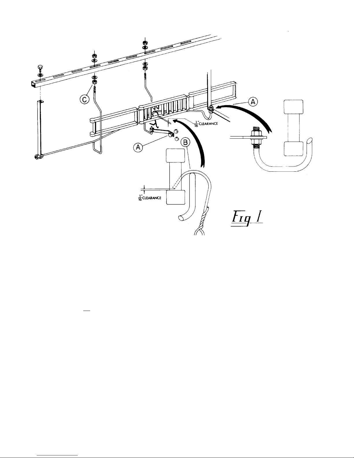
ADJUSTING DROP-OFF
IMPORTANT!
1. Warning! When placing hanger on conveyor, open end of hanger must point toward cabinet.
A hanger placed on the conveyor backwards may result in a damaged garment.
2. Any make of wire hanger with sufficient clearance may be used on the automatic tunnel
conveyor, but all hangers should be the same to insure proper drop-off.
3. Adjust drop-off so that it barely misses the conveyor links by adjusting nuts on the bracket
inside of tunnel as illustrated above in A of Figure 1.
4. Using the selected hanger, then adjust the height of the drop-off as illustrated above in B of
Figure 1.
5. Adjust lower end of drop-off to desired height for proper sliding of garment and for proper
feed to screw conveyor if used (C of Figure 1).
6. Run a few garments through the tunnel and check to be sure that there is clearance at the
top of hanger, and that drop-off operation is smooth. If hanger does not have enough
clearance perhaps a change in hanger is needed. If the drop-off is not smooth, repeat steps
3 through 5 above.
Page 8
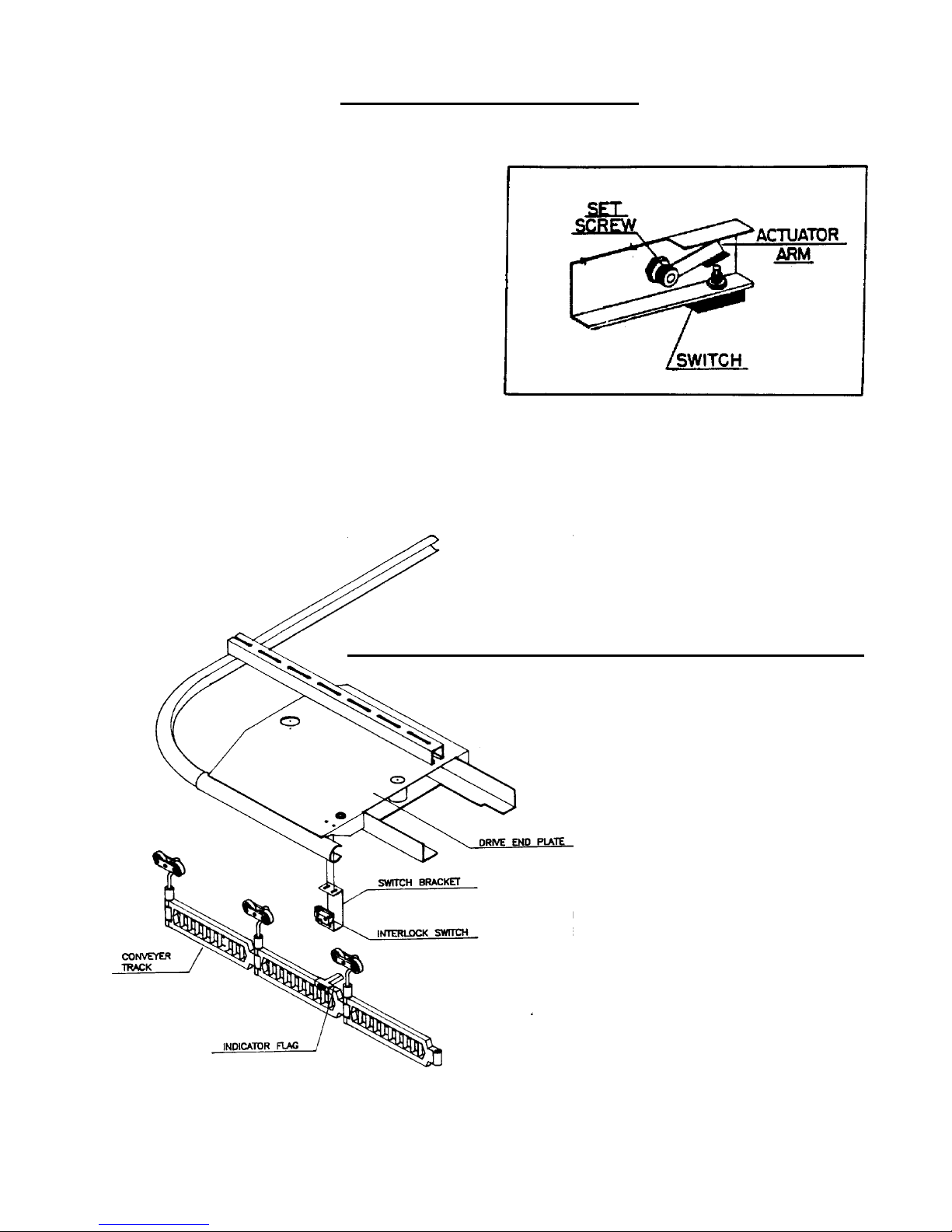
ADJUSTMENT OF DOORS
1. Loosen the set screws that hold the
Actuator arm onto the door lever.
2. Open the doors until they are wide
enough for garment travel; hold in
place.
3. Press Actuator arm onto door switch
so that switch is completely depressed.
Tighten set screws onto door lever.
ADJUSTMENT OF CONVERTER INTERLOCK
1. Interlock switch should be positioned so
that when a flag indicator activates the
conveyor interlock switch, a load of
garments are completely inside the
tunnel.
2. If the adjustment is off, loosen the screws
on the conveyor interlock switch bracket
and slide bracket until properly
positioned.
Page 9
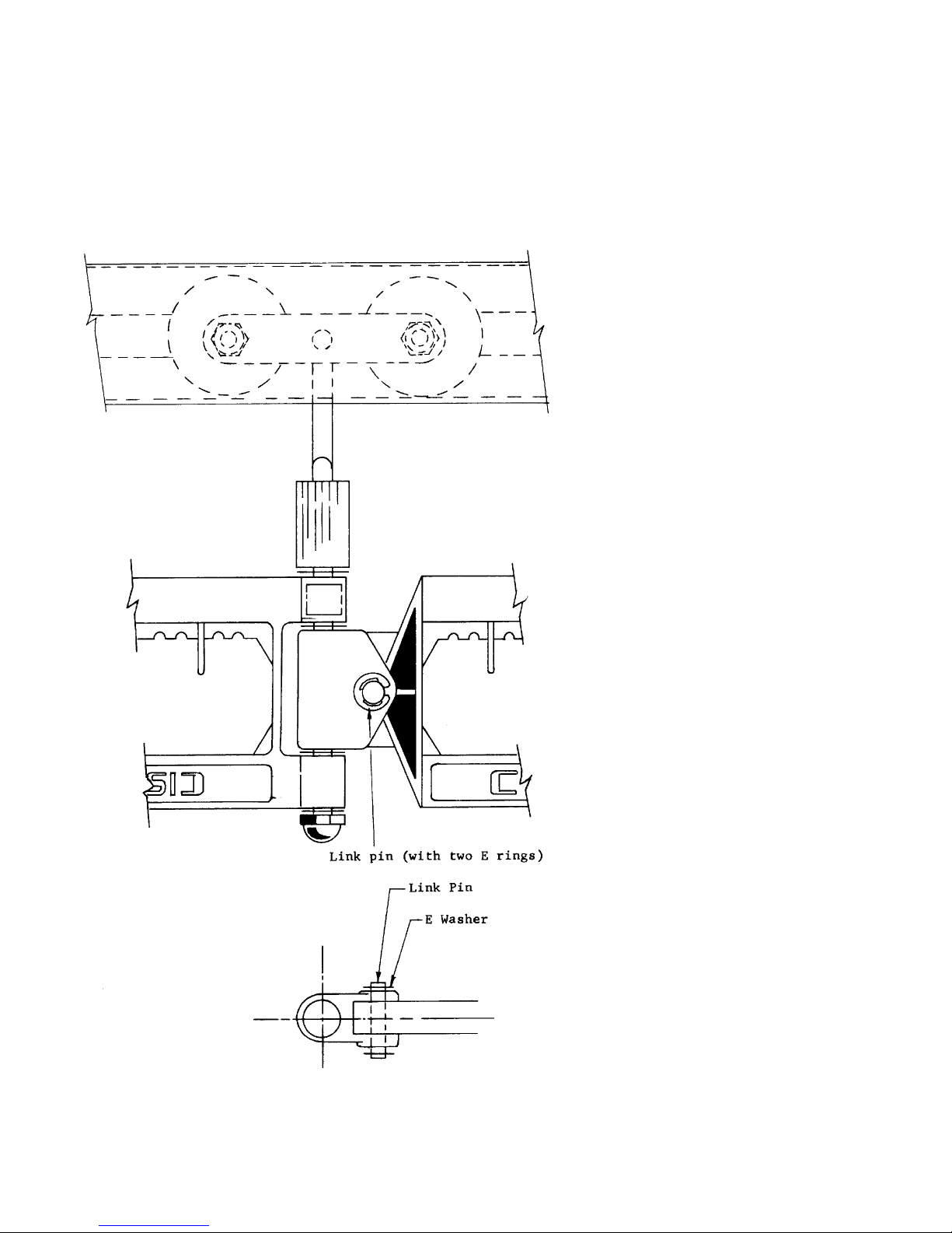
INSTALLATION INSTRUCTIONS
For Connecting Floor Model Link Sections on Conveyor
1. Move connecting link
preferably to a straight
portion of the track.
2. Insert the connecting pin
(as illustrated) and replace
the E ring in the Groove
of the pin.
NOTE: Inspect E ring to
be certain that it has
snapped securely into the
groove of the pin.
Page 10
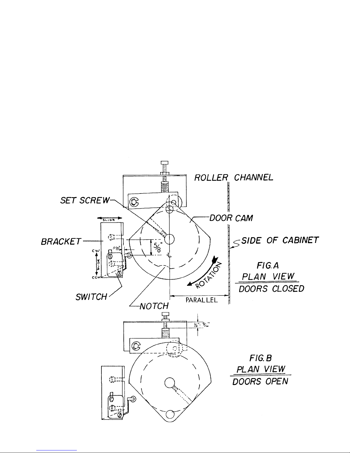
DOOR INTERLOCK
SWITCH ADJUSTMENT
1. With doors in closed position the switch should be set as shown in Figure A.
2. Figure B shows correct cam and roller alignment with doors in open position. To
check cam and roller alignment press start button and when the doors stop in the
open position, turn off main power switch. Check to see that the roller is centered
in the notch on the cam hub. If the cam has not rotated a full 180º to allow roller to
drop into notch, adjust the switch clockwise (up) approximately 1/16. If the cam
has rotated more than 180º, adjust the switch counter clockwise (down)
approximately 1/16. Repeat until roller drops into notch.
Page 11
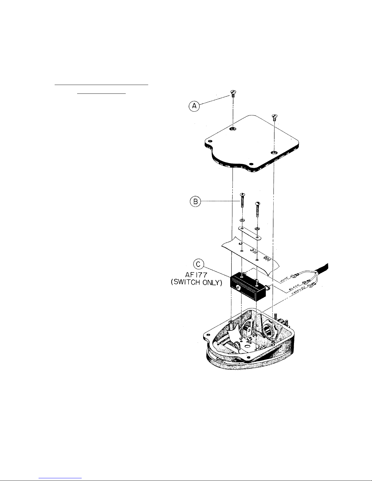
INSTALLATION INSTRUCTIONS
FOR AF177 MICRO SWITCH
PT527 Foot Pedal Complete
w/3-Wire Cord
1. Turn switch to inverted position and
remove screws (A) as illustrated.
2. Lift off base plate pad.
3. Remove screws marked (B) as
shown.
4. Remove washers, plate, insulation
and switch.
5. Remove wires from old switch.
Reinstall wires on new switch (C)
and tighten securely.
6. Reinstall switch, insulation, plate,
washers and screws. Tighten
securely.
7. Reinstall base-plate-pad and screws.
Tighten securely.
Page 12
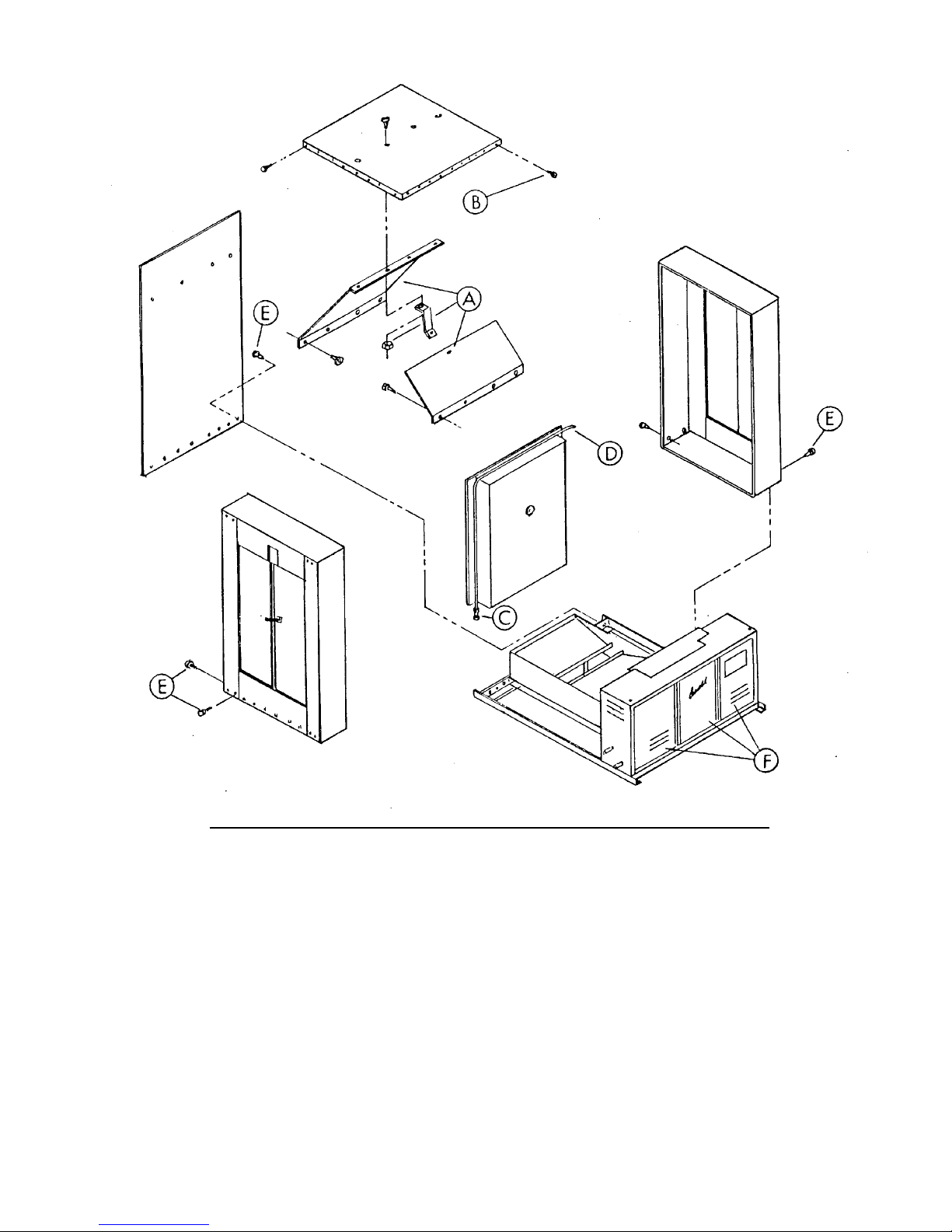
INSTRUCTIONS FOR DISASSEMBLING TUNNEL
1. Remove nuts, bolts, and screws holding Drip Pans (A) in place and remove Drip
Pan.
2. Remove screws (B) around the top and remove top.
3. Remove Center Door and open End Doors (F).
4. Remove Thermometer Bulb by loosening clip that holds it.
5. Break Union (C) and disconnect Copper Tube (D) to Condenser.
6. Remove Upper Linkage between Doors and remove Door Spring.
7. Remove Screws (E) located around the bottom of the Tunnel and the top of Controls
Section.
8. Remove End Sections and Side Panels.
9. To reassemble, follow procedure in reverse.
Page 13
 Loading...