

Cissell FFMAN57, FFCD, FFCG Owner's Manual
FF
Form
Finisher
Models
FFCD
FFCG
OWNERS MANUAL
CISSELL MANUFACTURING COMPANY
HEADQUARTERS PHONE: (502) 587-1292
831 SOUTH FIRST ST. SALES FAX: (502) 585-3625
P.O. BOX 32270 SERVICE/PARTS FAX: (502) 681-1275
LOUISVILLE, KY 40232-2270
THIS MANUAL MUST BE GIVEN TO THE EQUIPMENT OWNER.
MAN57 8/98
Page 1

WARRANTY
The Cissell Manufacturing Company (Cissell) warrants all new equipment (and the original parts thereof) to be free from
defects in material or workmanship for a period of one (1) year from the date of sale thereof to an original purchaser for
use, except as hereinafter provided. With respect to non-durable parts normally requiring replacement in less than one (1)
year due to normal wear and tear, including, but not limited to, cloth goods, valve discs, hoses, and iron cords, and with
respect to all new repair or replacement parts for Cissell equipment for which the one (1) year warranty period has expired,
or for all new repair or replacement parts for equipment other than Cissell equipment, the warranty period is limited to
ninety (90) days from date of sale. The warranty period on each new replacement part furnished by Cissell in fulfillment
of the warranty on new equipment or parts shall be for the unexpired portion of the original warranty period on the part
replaced.
With respect to electric motors, coin meters and other accessories furnished with the new equipment, but not manufactured
by Cissell, the warranty is limited to that provided by the respective manufacturer.
Cissell's total liability arising out of the manufacture and sale of new equipment and parts, whether under the warranty or
caused by Cissell's negligence or otherwise, shall be limited to Cissell repairing or replacing, at its option, any defective
equipment or part returned f.o.b. Cissell's factory, transportation prepaid, within the applicable warranty period and found
by Cissell to have been defective, and in no event shall Cissell be liable for damages of any kind, whether for any injury to
persons or property or for any special or consequential damages. The liability of Cissell does not include furnishing (or
paying for) any labor such as that required to service, remove or install; to diagnose troubles; to adjust, remove or replace
defective equipment or a part; nor does it include any responsibility for transportation expense which is involved therein.
The warranty of Cissell is contingent upon installation and use of its equipment under normal operating conditions. The
warranty is void on equipment or parts; that have been subjected to misuse, accident, or negligent damage; operated under
loads, pressures, speeds, electrical connections, plumbing, or conditions other than those specified by Cissell; operated
or repaired with other than genuine Cissell replacement parts; damaged by fire, flood, vandalism, or such other causes
beyond the control of Cissell; altered or repaired in any way that effects the reliability or detracts from its performance,
or; which have had the identification plate, or serial number, altered, defaced, or removed.
No defective equipment or part may be returned to Cissell for repair or replacement without prior written authorization
from Cissell. Charges for unauthorized repairs will not be accepted or paid by Cissell.
CISSELL MAKES NO OTHER EXPRESS OR IMPLIED WARRANTY, STATUTORY OR OTHERWISE, CONCERNING
THE EQUIPMENT OR PARTS INCLUDING, WITHOUT LIMITATION, A WARRANTY OF FITNESS FOR A PARTICULAR
PURPOSE, OR A WARRANTY OF MERCHANTABILITY. THE WARRANTIES GIVEN ABOVE ARE EXPRESSLY IN
LIEU OF ALL OTHER WARRANTIES, EXPRESS OR IMPLIED. CISSELL NEITHER ASSUMES, NOR AUTHORIZES
ANY PERSON TO ASSUME FOR IT, ANY OTHER WARRANTY OR LIABILITY IN CONNECTION WITH THE
MANUFACTURE, USE OR SALE OF ITS EQUIPMENT OR PARTS.
For warranty service, contact the Distributor from whom the Cissell equipment or part was purchased. If the Distributor
cannot be reached, contact Cissell.
Page 2
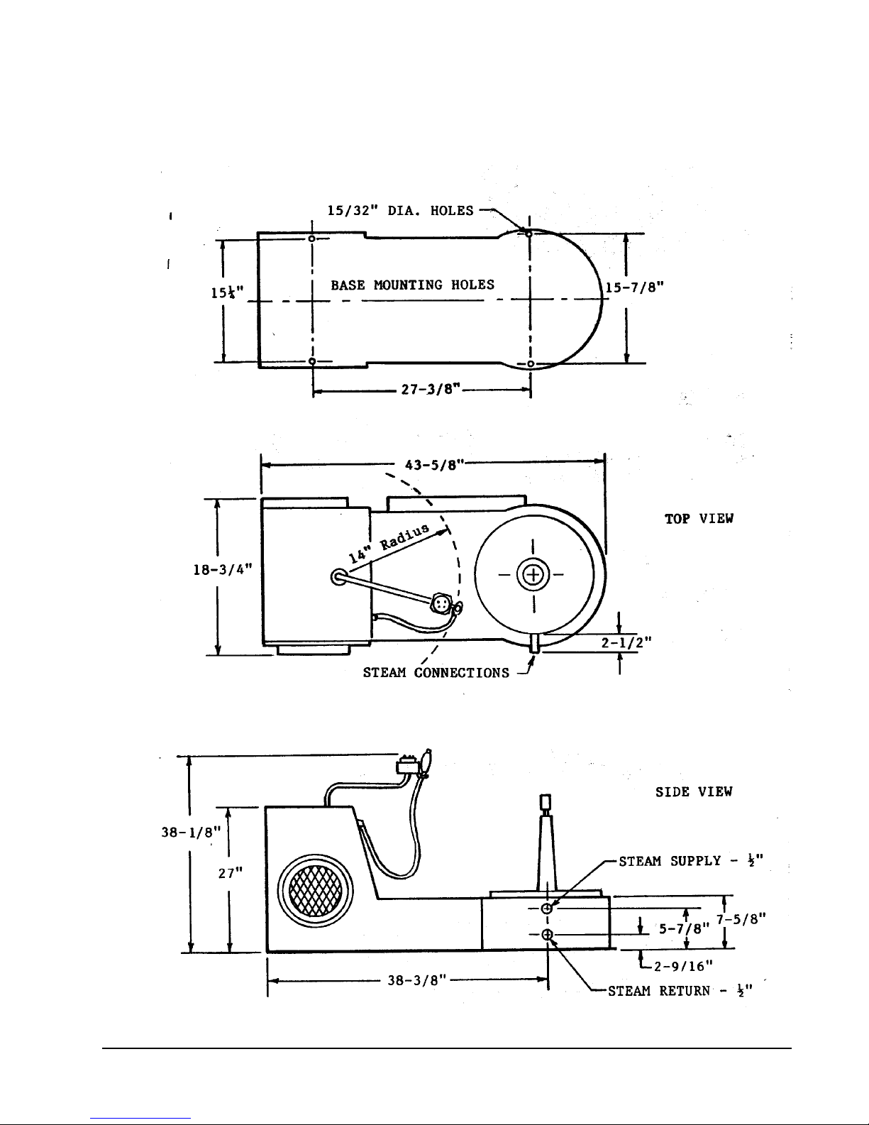
FF FORM FINISHER
LOW BASE OVERALL DIMENSIONS
Page 3
SPECIFICATIONS
Cissell Form Finisher includes one set of #11 Sleevers, one set of #24 Sleevers, and two
Cissell Vent Clamps. Electric Motor: 1/3 (250 w) HP, 1725 RPM, 115 or 230 Volt, 60
Cycle, AC, Single Phase. Other voltages and currents available.
Operating Steam Pressure ............................................... 100 P.S.I.G. Max. (6.9 bars)
Boiler HP Approx. 2 (1.5 kw) Depth ............................................... 57 (145 cm)
Steam Sply. & Ret. .... 1/2 (1.27 cm) Height ............................................ 61 (155 cm)
Swinging Radium 19 (48 cm) Width.................................................... 22 (56 cm)
Net Weight .............................................................................................. 245 lbs. (111 kg)
Approximate Shipping Weights: Domestic ....................................... 290 lbs. (132 kg)
Export.............................................. 435 lbs. (197 kg)
Export Shipping
Diminsions ................................................... 61 (155 cm) x 30 (76 cm) x 44 (112 cm)
Cubic Feet Export Crating ....................................................................... 46.6 (1.32 m3)
When ordering specify voltage desired.
CISSELL FORM FINISHER - with Taller Revolving Assembly which differs from specifications for standard model given above:
Height ............................................................................................................... 67 (170 cm)
Net Weight Approx. ................................................................................. 250 lbs. (113 kg)
Approximate Shipping Weight: Domestic ......................................... 295 lbs. (134 kg)
Export.......................................... 435 lbs. (197 kg)
Export Shipping
Dimensions ........................................ 61 (175 cm) x 30 (76 cm) x 44 (112 cm)
Cubic Feet Export Crating ..................................................... Approx. 46.6 (1.32 m3)
THE CISSELL FORM FINISHER IS MANUFACTURED UNDER ONE OR MORE OF THE FOLLOWING PATENTS: 2,459,962; 2,736,471;
2,736,472; 2,805,009; 2,998,171; 2,889,969; 2,895,659; 2,948,443; 3,006,516; 3,033,429; 3,051,358; 3,058,635; 3,140,830. OTHER PATS. APPLIED
FOR.
NOTE: All dimensions are approximate and may vary with adjustment
or the addition of optional equipment. Information in this manual is
subject to change without prior notice.
Page 4

CISSELL FORM FINISHER
GENERAL INFORMATION
UNCRATE FINISHER. Check voltage and current on name plate of motor before installing machine.
Electrical Specification of Relay and Solenoid (within junction box on Finisher) must be the same as
the motor. Do not remove the plastic protective cover on the Nylon Form until the machine is ready to
be placed in operation.
INSTALLATION
SET FINISHER IN POSITION. Grip handle of front and rear clamps and lift revolving form about
22 to remove from base.
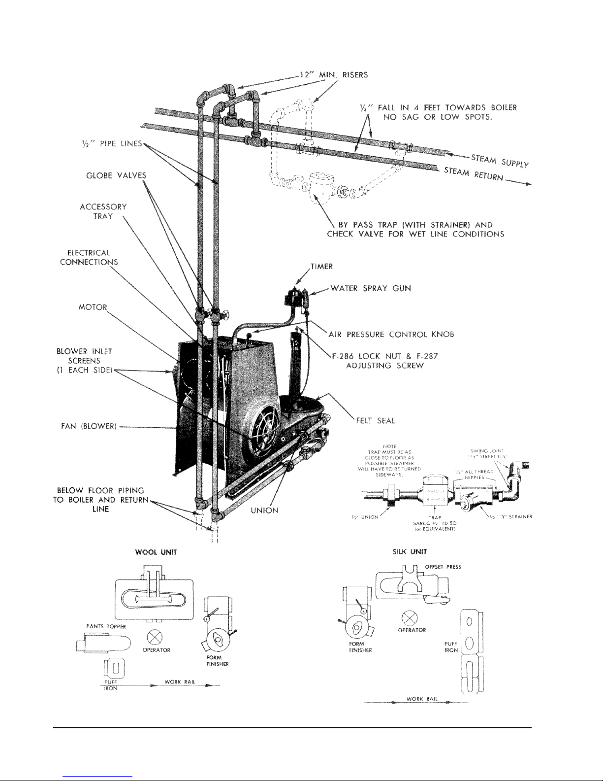
STEAM SUPPLY line must fall towards machine (without water pockets.) Connect Finisher to steam
supply line with union, globe valve and 12 (or more) riser, as illustrated on reverse side. If Finisher
is located at the end of stream line, extend line at least 4 feet beyond machine, and install a by-pass
trap and check valve as illustrated in dotted lines; if gravity return, omit trap.
STEAM RETURN line must fall towards boiler (without water pockets). Connect Finisher to steam
return line with a swing connection, unions, strainer, trap, check valve and 12 (or more) riser as
illustrated on reverse side. Inspect trap carefully for inlet and outlet markings and install swing
connection, trap, and check valve as close to machine as possible with trap as close to floor as
practical.
Use a separate trap for the Finisher; keep it clean and in good working condition for best performance. If steam line is gravity returned to boiler, omit trap.
IMPORTANT: Before installing trap and connecting steam return line, open globe valve in steam
supply connection and flush pipe dope, borings and other foreign matter, from steam connections and
steam chamber within Finisher. Failure to do this may later cause trap trouble.
THE STANDARD Cissell Form Finisher has single phase motors and controls.
MAKE ELECTRICAL CONNECTIONS as indicated on wiring diagram attached to inside cover of
electrical junction box on Finisher. Voltage and current of power line must be the same as the Electrical Specifications of the motor, relay and solenoid.
FOR SINGLE PHASE CURRENT (120V), connect the black and white power leads of the Finisher to
an approved fused disconnect switch in the power line.
(continued)
Page 5
Page 6

TO CONNECT STANDARD, SINGLE PHASE MACHINE TO THREE PHASE CURRENT, connect
the black and white power leads of the Finisher to any two terminals of an approved fused disconnect
switch in the three phase power line.
IMPORTANT: Consult your local electrical code, before making any electrical connections, and be
certain that the electrical installation conforms with all local requirements.
Always check wiring before closing the disconnect switch.
Operate the Steam Cycle a couple of times before installing the Revolving Assembly.
OPEN SLEEVE ZIPPERS ON EACH SIDE OF FORM; insert hand through zipper openings, and
remove paper between shoulder form and nylon form, which is a
protective covering for shipping only. Remove paper covering on front and rear clamps; grip handles
of front and rear clamps, and replace revolving form on base. Finisher is now ready for operation.
REMOVE NYLON FORM from finisher at frequent intervals for cleaning, as determined by its soiled
condition. WET clean only ... do NOT dryclean. After wet cleaning, the nylon form should be extracted and blown dry on a wind whip. KEEP NYLON FORM CLEAN. Nylon Fabric acts as a filter
in operation, collecting dust and lint, etc., which clogs pores of fabric, greatly reducing its efficient
operation. FAILURE to keep form clean may cause transfer of soil from form to lining of garments.
REPAIR HOLES OR WORN SPOTS in nylon form to extend its useful life; REPLACE when holes or
worn spots are beyond repair. A defective or worn nylon form will cause the machine to operate
unsatisfactorily.
CAUTION
Use only genuine CISSELL FD10 or FG10 replacement Nylon Forms for best results. The fabric for
Cissell Nylon Forms is especially woven (and cut to an exact pattern) to give the correct porosity for
proper steaming and drying. Remember, your CISSELL Form Finisher depends entirely on the Nylon
Form for proper operation.
Page 7

CISSELL FORM FINISHER
MECHANICAL ADJUSTMENTS
ADJUSTABLE LEVERS - Move back and forth to regulate size of nylon form at waist, hip and
lower positions. Markings on Index plates enable operator to re-set levers to the exact adjustments
for a known garment style or size. Rotate knob on lever clockwise to lock; counter-clockwise 1/4
to 1/2 turn to unlock; move knob
forward to increase size of form, reverse movement to decrease. Avoid excessive tightening or
loosening of knob as this will delay
adjustments and retard production.
WAIST CONTROL - Regulates expansion at waist line --- for finishing short jackets and childrens
garments.
HIP CONTROL - Regulates expansion at hip line --- for finishing sack coats,
medium length jackets, blouses, etc.
LOWER CONTROL - Regulated expansion at bottom --- for finishing topcoats,
overcoats, raincoats, etc.
ARM ZIPPERS (on both sides) - Open, for sleeved garments; close, for sleeveless; or adjust
between open and closed positions to provide required amount of steam and air within sleeves.
FRONT CLAMP - For clamping front edges of sack coats, jackets, overcoats, housecoats, robes,
front-buttoned dresses and blouses, etc.; - raises 5 for smallest childs garment. Front edges must
overlap at least 3 with buttons on outside. (Push lever to lock, squeeze trigger to unlock.)
BACK CLAMP - For clamping rear vent of sack coats, jackets, topcoats, raincoats, overcoats, etc.,
or center kick-pleat in rear panel of skirt. (Push lever to lock, squeeze trigger to unlock.) Separate
vent clamp furnished for holding rear vent of extremely short garments.
FORM - Rotates 360o (in either direction) to obtain the most convenient loading position. The back
clamp has two open positions. In the extreme open position, the handle of the back clamp will
strike the timer assembly, when rotated 360o. To avoid this, move clamp to intermediate position.
Avoid rotating form for each garment, as this is tiresome and will greatly reduce production. It is
best for the operator to step from front to rear, as required.
SHOULDER ADJUSTMENT - For adjusting width of shoulder to size of garment. (Rotate knob
clockwise to increase width; counter-clockwise to decrease).
Page 8

CISSELL FORM FINISHER
(Operating Instructions)
Read General Information on Preceding Pages Before Reading Operating Instructions below.
-IMPORTANT-
For best performance, and maximum production, avoid unnecessary adjustments. Finish, in sequence,
garments of same size and type. This will eliminate adjusting waist, hip, or lower controls for each
garment; increase production, and provide maximum life for the nylon form. Time can also be saved
by finishing small garments first, then progressively moving from group to group, until largest size and
type is reached.
Selection from unfinished garments may be made by the operator directly from the incoming speed
rail, without separate sorting, classifying or grouping. It is best to REDUCE FORM TO ITS SMALLEST SIZE WITH AIR OFF, or with AIR CONTROL in Minimum Setting. Controls can be released
easily to allow air to expand form to size of garment with AIR ON.
AIR CONTROL
AIR PRESSURE - can be adjusted, at front of machine, from maximum to minimum, or to any intermediate stage. Markings 1-2-3 help operator to identify air pressure for repeat operations of similar
garments.
FOR HEAVY GARMENTS, keep air in maximum position, or adjust to any lower pressure
desired during step number 2 under finishing instructions.
FOR SHEER, delicate fabrics, reduce air to minimum or adjust to any higher pressure desired
during step number 2 under finishing instructions.
COAT FINISHING
Open Arm Zippers in Nylon Form for All Garments With Sleeves; Keep Closed for Sleeveless Garments.
1. PLACE COAT ON FORM FINISHER. With each hand, grasp front edges of coat lapels just
below gored seams. Swing coat over and around form and place coat to hang evenly. STRAIGHTEN
COAT - pocket flaps, collar lapels, etc.
Pull two front edges of coat forward; overlap front edges at least 3 from bottom of coat to
lapels with buttons on outside; close front clamp. Front clamp raises or lowers 5 to permit proper
positioning for long or short coats. Close back clamp on rear vent of topcoats, raincoats, or overcoats.
(Place separate vent clamp on rear vent of extremely short garments.)
Page 9

2. ADJUST FORM. Set Timer for continuous operation of air, move air control to
minimum setting. Adjust waist, hip, and lower controls as required. Never allow
nylon form to be larger than garment. It is unnecessary to adjust hip and lower
controls for childrens garments or very short jackets; or to adjust the lower
control for sack coats or medium length jackets. The control governing the width of
the form immediately below the lower edges of the garment is the important
adjustment; the control governing the width of the form within the garment is
next. Insert expanding sleever in one sleeve - POSITION CORRECTLY. Before inserting
second sleever, step No. 3 may be started.
3. STEAM AND DRY COAT. Move Air Control to obtain required pressure. Set Timer for
automatic steaming and drying. With Steam on, operator may proceed immediately with touchup of garment previously removed from form, as steaming and drying is fully automatic.
4. REMOVE COAT. With AIR OFF, withdraw sleevers, relieving spring tension while
withdrawing. Release front and rear clamps. (Remove coat, and place on hanger or press for
touch-up.) If next garment is a smaller size, reduce form to its smallest size with air off. It is
unnecessary to make repeated adjustments for successive garments when they are approximately
the same size and type.
PRODUCTION HINTS
In many instances, the nylon form can be expanded only to the inner lining of a garment, when it is
smaller than the garment. To solve this problem, adjust hip and lower width controls to the lining, or
as large as possible, whichever comes first. Then, during the steam cycle, pull the lower edges of the
garment until the entire garment is progressively brought into contact with the form for steaming; then
follow with normal drying procedure.
When the front clamp is used on full-nap soft fabrics, interchange the lapels after the initial steaming
period and resteam. During the drying cycle, release front (and rear) clamps slowly to avoid impression marks.
Page 10
 Loading...