

Washer-Extractors
Pocket Hardmount Variable-Speed
PS40 Control
Refer to Page 4 for Model Identification
Installation/Operation Supplement
Keep These Instructions for Future Reference.
(If this machine changes ownership, this manual must accompany machine.)
www.comlaundry.com
PHM1397C
PHM1397C
Part No. C002882
March 2008


Installation/Operation Supplement
Table of
Contents
Safety Information.............................................................................. 2
Explanation of Safety Messages........................................................... 2
Important Safety Instructions ............................................................... 2
Model Identification ............................................................................. 4
Specifications and Dimensions........................................................... 5
High Speed Models............................................................................... 5
Medium Speed Models......................................................................... 8
Machine Dimensions ............................................................................ 10
40 Pound Models ............................................................................. 11
60 Pound Models ............................................................................. 12
80 Pound Models ............................................................................. 13
100 Pound Models ........................................................................... 14
125 Pound Models ........................................................................... 15
140 Pound Models ........................................................................... 16
175 Pound Models ........................................................................... 17
Front and Rear Features........................................................................ 18
Floor Load Data.................................................................................... 19
Installation Instructions ........................................................................ 21
Surface ............................................................................................. 21
Anchors ............................................................................................ 21
Mounting.......................................................................................... 21
Mounting Bolt Installation Requirements ............................................ 22
Location ........................................................................................... 22
Clearances ........................................................................................ 22
40 Pound Models ............................................................................. 23
60, 80 and 100 Pound Models.......................................................... 25
125, 140 and 175 Pound Models...................................................... 27
Provisions for 50 Hz Installations.................................................... 29
Operation............................................................................................. 31
General Operation Instructions............................................................. 32
Operating PS40 Control........................................................................ 32
Disposal of Unit................................................................................... 34
© Copyright 2008, Alliance Laundry Systems LLC
All rights reserved. No part of the contents of this book may be reproduced or transmitted in any form or by any
means without the expressed written consent of the publisher.
C002882
© Copyright, Alliance Laundry Systems LLC – DO NOT COPY or TRANSMIT
1
Installation/Operation Supplement
Safety Information
Explanation of Safety Messages
Precautionary statements (“DANGER,” “WARNING,”
and “CAUTION”), followed by specific instructions,
are found in this manual and on machine decals. These
precautions are intended for the personal safety of the
operator, user, servicer, and those maintaining the
machine.
DANGER
DANGER indicates the presence of a
hazard that will cause severe personal
injury, death, or substantial property
damage if the danger is ignored.
WARNING
WARNING indicates the presence of a
hazard that can cause severe personal
injury, death, or substantial property
damage if the warning is ignored.
Important Safety Instructions
WARNING
To reduce the risk of fire, electric shock,
serious injury or death to persons when
using your washer, follow these basic
precautions:
W023
1. Read all instructions before using the washer.
2. Refer to the GROUNDING INSTRUCTIONS in
the INSTALLATION manual for the proper
grounding of the washer.
3. Do not wash textiles that have been previously
cleaned in, washed in, soaked in, or spotted with
gasoline, kerosene, waxes, cooking oils, drycleaning solvents, or other flammable or
explosive substances as they give off vapors that
could ignite or explode.
4. Do not add gasoline, dry-cleaning solvents, or
other flammable or explosive substances to the
wash water. These substances give off vapors that
could ignite or explode.
CAUTION
CAUTION indicates the presence of a
hazard that will or can cause minor
personal injury or property damage if the
caution is ignored.
Additional precautionary statements (“IMPORTANT”
and “NOTE”) are followed by specific instructions.
IMPORTANT: The word “IMPORTANT” is used
to inform the reader of specific procedures where
minor machine damage will occur if the procedure
is not followed.
NOTE: The word “NOTE” is used to communicate
installation, operation, maintenance or servicing
information that is important but not hazard
related.
5. Under certain conditions, hydrogen gas may be
produced in a hot water system that has not been
used for two weeks or more. HYDROGEN GAS
IS EXPLOSIVE. If the hot water system has not
been used for such a period, before using a
washing machine or combination washer-dryer,
turn on all hot water faucets and let the water
flow from each for several minutes. This will
release any accumulated hydrogen gas. The gas is
flammable, do not smoke or use an open flame
during this time.
6. Do not allow children to play on or in the washer.
Close supervision of children is necessary when
the washer is used near children. This is a safety
rule for all appliances.
7. Before the washer is removed from service or
discarded, remove the door to the washing
compartment.
8. Do not reach into the washer if the wash drum is
moving.
2
© Copyright, Alliance Laundry Systems LLC – DO NOT COPY or TRANSMIT C002882

Installation/Operation Supplement
9. Do not install or store the washer where it will be
exposed to water and/or weather.
10. Do not tamper with the controls.
11. Do not repair or replace any part of the washer, or
attempt any servicing unless specifically
recommended in the user-maintenance
instructions or in published user-repair
instructions that the user understands and has the
skills to carry out.
12. To reduce the risk of an electric shock or fire, DO
NOT use an extension cord or an adapter to
connect the washer to the electrical power source.
13. Use washer only for its intended purpose,
washing textiles.
14. Never wash machine parts or automotive parts in
the machine. This could result in serious damage
to the basket.
15. ALWAYS disconnect the washer from electrical
supply before attempting any service. Disconnect
the power cord by grasping the plug, not the cord.
16. Install the washer according to the
INSTALLATION INSTRUCTIONS. All
connections for water, drain, electrical power and
grounding must comply with local codes and be
made by licensed personnel when required.
17. To reduce the risk of fire, textiles which have
traces of any flammable substances such as
vegetable oil, cooking oil, machine oil,
flammable chemicals, thinner, etc., or anything
containing wax or chemicals such as in mops and
cleaning cloths, must not be put into the washer.
These flammable substances may cause the
fabric to catch on fire by itself.
18. Do not use fabric softeners or products to
eliminate static unless recommended by the
manufacturer of the fabric softener or product.
20. Be sure water connections have a shut-off valve
and that fill hose connections are tight. CLOSE
the shut-off valves at the end of each wash day.
21. Loading door MUST BE CLOSED any time the
washer is to fill, tumble or spin. DO NOT bypass
the loading door switch by permitting the washer
to operate with the loading door open.
22. Always read and follow manufacturer’s
instructions on packages of laundry and cleaning
aids. Heed all warnings or precautions. To reduce
the risk of poisoning or chemical burns, keep
them out of the reach of children at all times
(preferably in a locked cabinet).
23. Always follow the fabric care instructions
supplied by the textile manufacturer.
24. Never operate the washer with any guards and/or
panels removed.
25. DO NOT operate the washer with missing or
broken parts.
26. DO NOT bypass any safety devices.
27. Failure to install, maintain, and/or operate this
washer according to the manufacturer’s
instructions may result in conditions which can
produce bodily injury and/or property damage.
NOTE: The WARNINGS and IMPORTANT
SAFETY INSTRUCTIONS appearing in this
manual are not meant to cover all possible
conditions and situations that may occur. Common
sense, caution and care must be exercised when
installing, maintaining, or operating the washer.
Any problems or conditions not understood should be
reported to the dealer, distributor, service agent or the
manufacturer.
19. Keep washer in good condition. Bumping or
dropping the washer can damage safety features.
If this occurs, have washer checked by a qualified
service person.
C002882
© Copyright, Alliance Laundry Systems LLC – DO NOT COPY or TRANSMIT
3

Installation/Operation Supplement
Model Identification
Information in this manual is applicable to these
models:
Medium Speed High Speed
40
Pound
60
Pound
80
Pound
100
Pound
125
Pound
140
Pound
175
Pound
CP040PMN1
CP040PMQ1
CP040PMX1
CPC40M
IP040PMN1
CP060PMN1
CP060PMQ1
CP060PMX1
CPC60M
IP060PMN1
CP080PMN1
CP080PMQ1
CPC80M
IP080PMN1
CP100PMN1
CP100PMQ1
CPC100M
IP100PMN1
Not Applicable
CP140PMN1
CP140PMQ1
CPC140M
IP140PMN1
Not Applicable
IP040PMQ1
IP040PMX1
IPH40M
IPH180
IP060PMQ1
IP060PMX1
IPH60M
IPH270
JP060PMQ1
IP080PMQ1
IPH80M
IPH370
IP100PMQ1
IPH100M
IPH460
JP100PMQ1
IP140PMQ1
IPH140M
IPH640
JP140PMQ1
CP040PHN1
CP040PHQ1
CP040PHX1
CPC40H
IP040PHN1
CP060PHN1
CP060PHQ1
CP060PHX1
CPC60H
IP060PHN1
CP080PHN1
CP080PHQ1
CPC80H
IP080PHN1
CP100PHN1
CP100PHQ1
CPC100H
IP100PHN1
CP125PHN1
CP125PHQ1
CPC125H
IP125PHN1
CP140PHN1
CP140PHQ1
CPC140H
IP140PHN1
CP175PHN1
CPC175H
IP175PHN1
IP040PHQ1
IP040PHX1
IPH40H
JP040PHN1
JP040PHQ1
IP060PHQ1
IP060PHX1
IPH60H
JP060PHN1
JP060PHQ1
IP080PHQ1
IPH80H
JP080PHN1
JP080PHQ1
IP100PHQ1
IPH100H
JP100PHN1
JP100PHQ1
IP125PHQ1
IPH125H
IPH570
JP125PHN1
IP140PHQ1
IPH140H
JP140PHN1
JP140PHQ1
IPH175H
IPH790
4
© Copyright, Alliance Laundry Systems LLC – DO NOT COPY or TRANSMIT
C002882
Installation/Operation Supplement
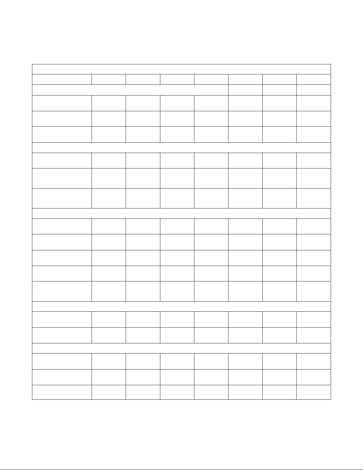
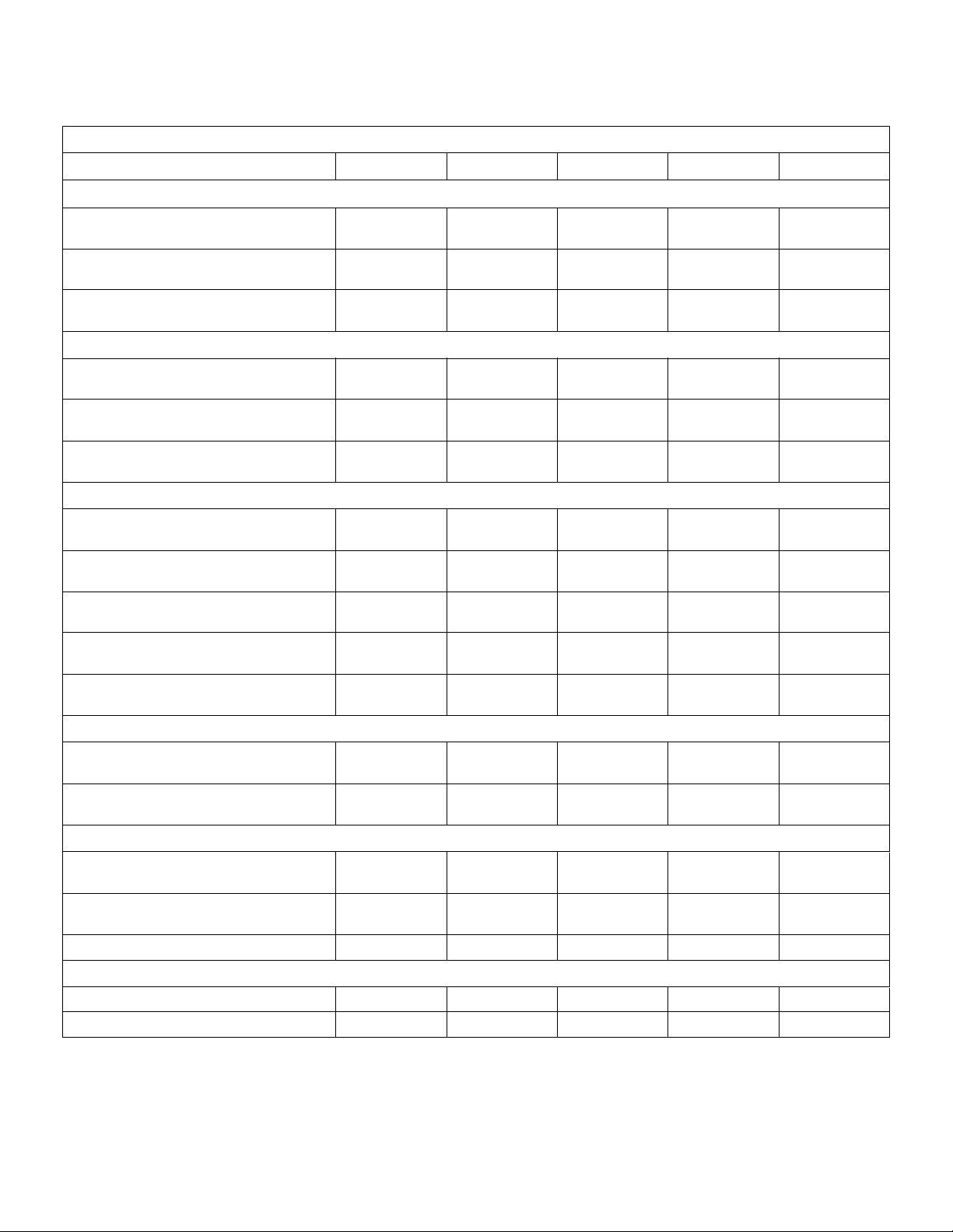
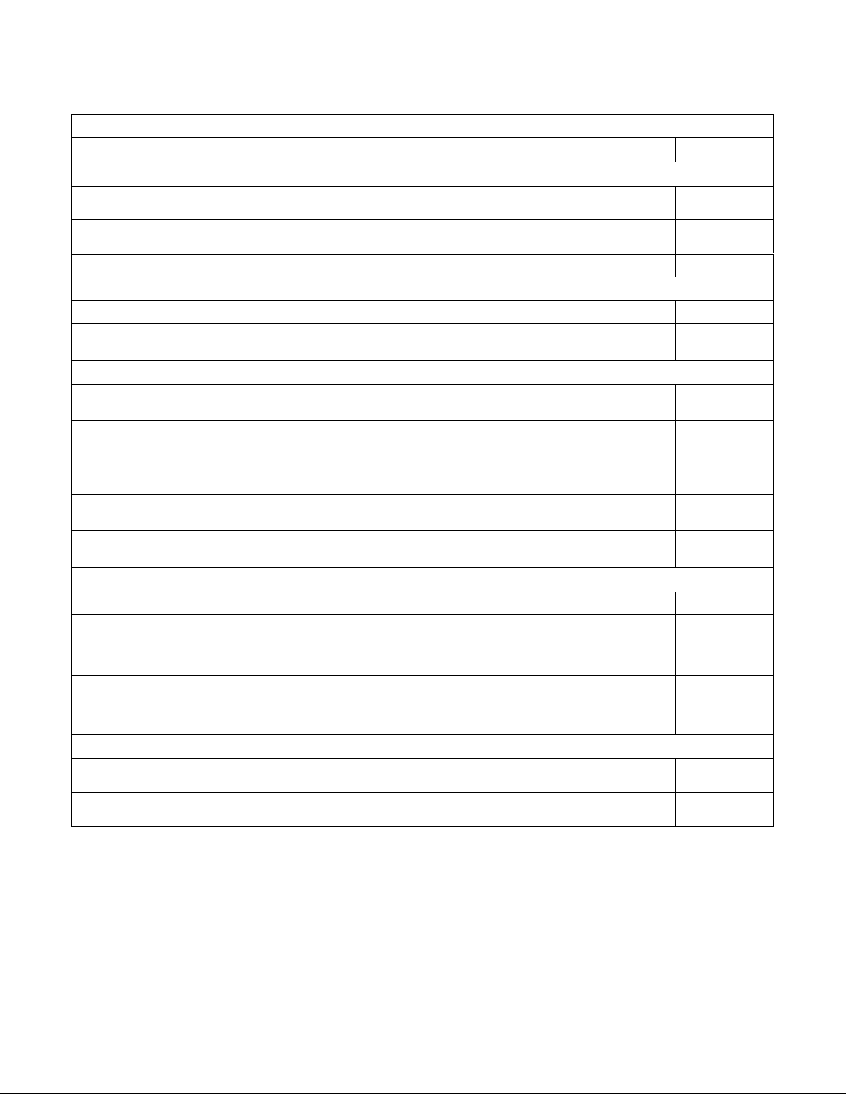
Specifications and Dimensions
High Speed Models
Models
Specifications 40H 60H 80H 100H 125H 140H 175H
Overall Dimensions
Overall Width,
mm (in.)
Overall Height,
mm (in.)
Overall Depth,
mm (in.)
Weight and Shipping Information
Net Weight,
kg (lbs.)
Domestic Shipping
Wei ght,
kg (lbs.)
Domestic Shipping
Vo lu m e,
m3 (ft.3)
813
(32)
1448
(57)
1158
(45.6)
768.2
(1690)
804.5
(1770)
1.78
(63)
876
(34.5)
1590
(62.6)
1213
(47.8)
815.9
(1795)
861.3
(1895)
2.18
(76.9)
1080
(42.5)
1778
(70)
1306
(51.4)
875.5
(1926)
920.9
(2026)
3.11
(110)
1080
(42.5)
1778
(70)
1433
(56.4)
985
(2167)
1030.5
(2267)
3.45
(122)
1430
(56.3)
1958
(77.1)
1425
(56.1)
1247
(2749)
1292
(2849)
4.53
(160)
1430
(56.3)
1958
(77.1)
1502
(59.1)
1375.9
(3027)
1421.3
(3127)
4.73
(167)
1430
(56.3)
1958
(77.1)
1626
(64)
1489.5
(3277)
1535
(3377)
5.16
(179)
Wash Cylinder Information
Cylinder Diameter,
mm (in.)
Cylinder Depth,
mm (in.)
Cylinder Volume,
l (ft.3)
Perforation Size,
mm (in.)
Cylinder Capacity 1:10
Fill Ratio,
kg (lbs.)
686
(27)
483
(19)
178.3
(6.3)
4.83
(0.19)
17.8
(39.3)
787
(31)
559
(22)
271.7
(9.6)
4.83
(0.19)
27.2
(60)
Door Opening Information
Door Opening Size,
mm (in.)
Height of Door Bottom
Above Floor, mm (in.)
381
(15)
648
(25.5)
432
(17)
730
(28.8)
Drain System
Overflow Size,
mm (in.)
Drain Outlet Size,
mm (in.)
Number of Drain
Outlets, (std/opt)
All specifications are subject to change without notification.
38.1
(1.5)
76.2
(3)
38.1
(1.5)
76.2
(3)
1/2 1/2 1/2 1/2 1/2 1/2 1/2
940
(37)
533
(21)
370.7
(13.1)
4.83
(0.19)
37
(81.6)
508
(20)
752
(29.6)
38.1
(1.5)
76.2
(3)
Table 1 (continued)
940
(37)
660
(26)
458.5
(16.2)
4.83
(0.19)
45.9
(101)
508
(20)
765
(30.1)
38.1
(1.5)
76.2
(3)
1092
(43)
610
(24)
569.2
(20.1)
4.83
(0.19)
57
(125)
622
(24.5)
837
(34)
76.2
(3)
76.2
(3)
1092
(43)
686
(27)
642.4
(22.7)
4.83
(0.19)
64.3
(141.7)
622
(24.5)
871
(34.3)
76.2
(3)
76.2
(3)
1092
(43)
813
(32)
759.9
(26.8)
4.83
(0.19)
79.5
(175)
622
(24.5)
884
(34.8)
76.2
(3)
76.2
(3)
C002882
© Copyright, Alliance Laundry Systems LLC – DO NOT COPY or TRANSMIT
5
Installation/Operation Supplement
Table 1 (continued)
Models
Specifications 40H 60H 80H 100H 125H 140H 175H
Water Inlet
Connection Size
Number of Inlets,
(std/opt)
3/4 NPT 3/4 NPT 3/4 NPT 3/4 NPT 3/4 NPT 1-1/4 NPT 1-1/4 NPT
2/3 2/3 2/3 2/3 2/3 2/3 2/3
Chemical Supply System
Number of Dry
Chemical
Compartments, (std/opt)
Number of Liquid
Supply Connections,
(std/opt)
1/5 1/5 1/5 1/5 1/5 1/5 1/5
6/12 6/12 6/12 6/12 6/12 6/12 6/12
Cylinder Speeds/Centrifugal Force Data
Low Wash Speed,
G-Force (RPM)
Wash Speed,
G-Force (RPM)
Balance Speed,
G-Force (RPM)
Low Extract Speed,
G-Force (RPM)
Medium Extract Speed,
G-Force (RPM)
High Extract Speed,
G-Force (RPM)
Maximum SmartSpin
Speed,
G-Force (RPM)
0.014
(6)
0.8
(46)
2
(72)
100
(511)
140
(605)
230
(775)
300
(885)
0.016
(6)
0.8
(43)
2
(67)
100
(477)
140
(564)
230
(723)
300
(826)
0.019
(6)
0.8
(39)
2
(62)
100
(437)
140
(516)
230
(662)
300
(756)
0.019
(6)
0.8
(39)
2
(62)
100
(437)
140
(516)
230
(662)
300
(756)
0.022
(6)
0.8
(36)
2
(57)
100
(405)
140
(479)
200
(573)
300
(701)
0.022
(6)
0.8
(36)
2
(57)
100
(405)
140
(479)
200
(573)
250
(640)
0.022
(6)
0.8
(36)
2
(57)
100
(405)
140
(479)
200
(573)
250
(640)
Drive Train Information
Number of Motors In
Drive Train
Drive Motor Power,
kW (hp)
1111111
2.3
(3)
3.7
(5)
(7.5)
Balance Detection
Vibration Switch
Installed
STD STD STD STD STD STD STD
Electrical Heating (Optional)
Total Electrical Heating
Capacity,
kW
Number of Electrical
Heating Elements
Electrical Heating
Element Size, kW
21.5@240V
21.5@480V
6 – 240V
6 – 480V
32.2@240V
21.5@480V
9 – 240V
6 – 480V
32.2@240V
21.5@480V
9 – 240V
6 – 480V
3333Not
Electrical Connections (Non-electric Heated Models)
Table 1 (continued)
6
© Copyright, Alliance Laundry Systems LLC – DO NOT COPY or TRANSMIT
5.6
5.6
(7.5)
32.2@240V
21.5@480V
9 – 240V
6 – 480V
7.5
(10)
Not
Applicable
Not
Applicable
Applicable
5.6
(7.5)
Not
Applicable
Not
Applicable
Not
Applicable
11.2
(15)
Not
Applicable
Not
Applicable
Not
Applicable
C002882

Installation/Operation Supplement
Table 1 (continued)
Specifications 40H 60H 80H 100H 125H 140H 175H
Max. Circuit Breaker
Size
(200-240V, 3P)
Max. Circuit Breaker
Size
(380-480V, 3P)
All specifications are subject to change without notification.
15 15 20 20 30 30 Not
15 15 15 15 15 15 20
Tab le 1
Applicable
C002882
© Copyright, Alliance Laundry Systems LLC – DO NOT COPY or TRANSMIT
7
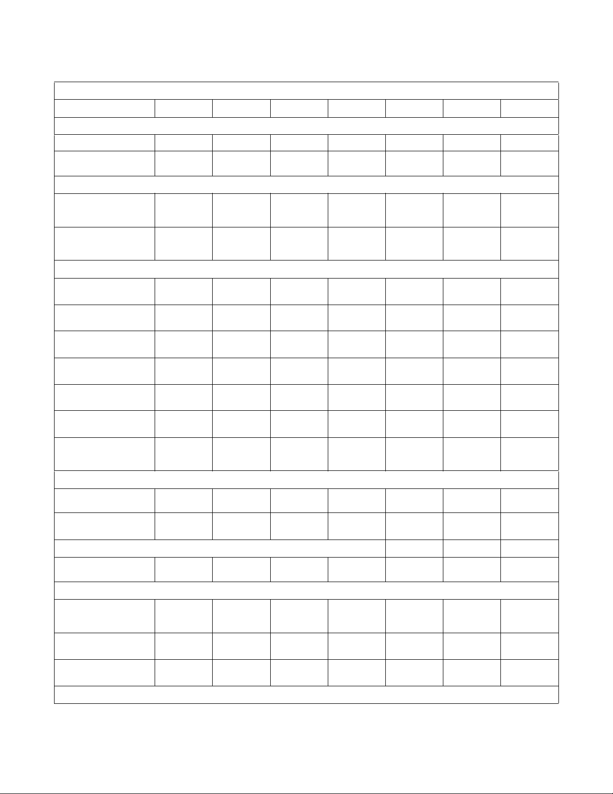
Installation/Operation Supplement
Medium Speed Models
Specifications 40M 60M 80M 100M 140M
Overall Dimensions
Overall Width,
mm (in.)
Overall Height,
mm (in.)
Overall Depth,
mm (in.)
Weight and Shipping Information
Net Weight,
kg (lbs.)
Domestic Shipping Weight,
kg (lbs.)
Domestic Shipping Volume,
m3 (ft.3)
Wash Cylinder Information
Cylinder Diameter,
mm (in.)
Cylinder Depth,
mm (in.)
Cylinder Volume,
l (ft.3)
Perforation Size,
mm (in.)
Cylinder Capacity 1:10 Fill Ratio,
kg (lbs.)
813
(32)
1448
(57)
1158
(45.6)
499
(110)
536
(1180)
1.78
(63)
686
(27)
483
(19)
178.3
(6.3)
4.83
(0.19)
17.8
(39.3)
Models
(34.5)
1590
(62.6)
1213
(47.8)
(1175)
(1250)
2.18
(76.9)
(31)
(22)
271.7
(9.6)
4.83
(0.19)
27.2
(60)
876
533
567
787
559
1080
(42.5)
1778
(70)
1306
(51.4)
740
(1630)
785
(1730)
3.11
(110)
940
(37)
533
(21)
370.7
(13.1)
4.83
(0.19)
37
(81.6)
1080
(42.5)
1778
(70)
1433
(56.4)
804
(1770)
849
(1870)
3.45
(122)
940
(37)
660
(26)
458.5
(16.2)
4.83
(0.19)
45.9
(101)
1276
(50.3)
1958
(77.1)
1502
(59.1)
1044
(2300)
1112
(2450)
4.73
(167)
1092
(43)
686
(27)
642.4
(22.7)
4.83
(0.19)
64.3
(141.7)
Door Opening Information
Door Opening Size,
mm (in.)
Height of Door Bottom Above Floor,
mm (in.)
381
(15)
648
(25.5)
Drain System
Overflow Size,
mm (in.)
Drain Outlet Size,
mm (in.)
Number of Drain Outlets, (std/opt)
38.1
(1.5)
76.2
(3)
1/2 1/2 1/2 1/2 1/2
Water Inlet
Connection Size
Number of Inlets, (std/opt)
All specifications are subject to change without notification.
8
© Copyright, Alliance Laundry Systems LLC – DO NOT COPY or TRANSMIT
3/4 NPT 3/4 NPT 3/4 NPT 3/4 NPT 1-1/4 NPT
2/3 2/3 2/3 2/3 2/3
432
(17)
730.3
(28.8)
38.1
(1.5)
76.2
(3)
Table 2 (continued)
508
(20)
751.8
(29.6)
38.1
(1.5)
76.2
(3)
508
(20)
765
(30.1)
38.1
(1.5)
76.2
(3)
622
(24.5)
871.2
(34.3)
76.2
(3)
76.2
(3)
C002882
Specifications 40M 60M 80M 100M 140M
Chemical Supply System
Number of Dry Chemical
compartments, (std/opt)
Number of Liquid Supply
Connections, (std/opt)
Liquid Supply Connection Size
1/51/51/51/51/5
6/12 6/12 6/12 6/12 6/12
1/2 NPT1/2 NPT1/2 NPT1/2 NPT1/2 NPT
Drive Train Information
Number of Motors In Drive Train
Drive Motor Power,
kW (hp)
2.3
(3)
Cylinder Speeds/Centrifugal Force Data
Low Wash Speed,
G-Force (RPM)
Was h S peed ,
G-Force (RPM)
Balance Speed,
G-Force (RPM)
Extract Speed,
G-Force (RPM)
Maximum SmartSpin Speed,
G-Force (RPM)
0.014
(6)
0.8
(46)
(72)
100
(511)
150
(625)
Installation/Operation Supplement
Table 2 (continued)
Models
11111
2.3
(3)
0.016
(6)
0.8
(43)
2
2
(67)
100
(477)
150
(585)
3.7
(5)
0.019
(6)
0.8
(39)
2
(62)
100
(437)
150
(535)
3.7
(5)
0.019
(6)
0.8
(39)
2
(62)
100
(437)
150
(535)
5.6
(7.5)
0.022
(6)
0.8
(36)
2
(57)
100
(405)
152
(500)
Balance Detection
Vibration Switch Installed
STDSTDSTDSTDSTD
Electrical Heating (Optional)
Total Electrical Heating Capacity, kW
Number of Electrical Heating
Elements
Electrical Heating Element Size, kW
21.5@240V
21.5@480V
6 – 240V
6 – 480V
3 3 3 3 Not Applicable
32.2@240V
21.5@480V
9 – 240V
6 – 480V
Electrical Connections (Non-electric Heated Models)
Max. Circuit Breaker Size
(200-240V, 3P)
Max. Circuit Breaker Size
(380-480V, 3P)
15 15 15 15 20
15 15 15 15 15
All specifications are subject to change without notification.
Tab le 2
32.2@240V
21.5@480V
9 – 240V
6 – 480V
32.2@240V
21.5@480V
9 – 240V
6 – 480V
Not Applicable
Not Applicable
C002882
© Copyright, Alliance Laundry Systems LLC – DO NOT COPY or TRANSMIT
9

Installation/Operation Supplement
Machine Dimensions
Dimensional Clearances
Allow a minimum of 600 mm (24 in.) at the rear and
450 mm (18 in.) at the sides for maintenance,
inspection, and adjustment. Allow at least 450 mm
(18 in.) between machines in multiple installations.
Machine dimensions are indicated in Figure 1 through
Figure 7. For minimum clearances, refer to Figure 9.
NOTE: The dimensions shown here are for
planning purposes only. They are approximate and
subject to normal manufacturing tolerances. If
exact dimensions are required for construction
purposes, contact the distributor or the
manufacturer. We reserve the right to make
changes at any time without notice
10
© Copyright, Alliance Laundry Systems LLC – DO NOT COPY or TRANSMIT
C002882

40 Pound Models
Installation/Operation Supplement
L
4
3
2
1
K
J
5
6
7
A
C
D
B
TOP
1 External Supply Connection 6 External Supply Wiring Connection
2 Auxiliary 7 Power Inlet
3 Hot Water 8 Steam Inlet
4 Cold Water 9 Auxiliary Drain
5 Greasing Points 10 Drain
FRONT
E
F
G
H
I
P
10
9
8
REAR
Figure 1
A
1158 mm (45.6 in.)
I
297 mm (11.7 in.)
O
N
M
PHM727N
PHM727N
B
C
D
E
F
G
H
C002882
813 mm (32 in.)
648 mm (25.5 in.)
572 mm (22.5 in.)
1448 mm (57 in.)
1321 mm (52 in.)
1219 mm (48 in.)
1118 mm (44 in.)
J
K
L
M
N
O
P
260 mm (10.25 in.)
491 mm (19.35 in.)
709 mm (27.93 in.)
554 mm (21.8 in.)
1092 mm (43 in.)
1306 mm (51.4 in.)
226 mm (8.88 in.)
Tab le 3
© Copyright, Alliance Laundry Systems LLC – DO NOT COPY or TRANSMIT
11

Installation/Operation Supplement
60 Pound Models
M
4
3
2
1
10
L
K
5
6
7
A
C
D
B
TOP
1 External Supply Connection 6 External Supply Wiring Connection
2 Auxiliary 7 Power Inlet
3 Hot Water 8 Auxiliary Drain
4 Cold Water 9 Drain
5 Greasing Points 10 Steam Inlet
FRONT
E
F
G
H
I
J
P
9
8
REAR
Figure 2
A
B
C
D
E
F
G
H
1213 mm (47.8 in.)
876 mm (34.5 in.)
732 mm (28.8 in.)
656 mm (25.8 in.)
1590 mm (62.6 in.)
1464 mm (57.62 in.)
1362 mm (53.62 in.)
1260 mm (49.62 in.)
I
J
K
L
M
N
O
P
978 mm (38.5 in.)
297 mm (11.7 in.)
292 mm (11.5 in.)
536 mm (21.1 in.)
754 mm (29.69 in.)
1234 mm (48.6 in.)
1450 mm (57.1 in.)
245 mm (9.63 in.)
O
N
PHM728N
PHM728N
12
Tab le 4
© Copyright, Alliance Laundry Systems LLC – DO NOT COPY or TRANSMIT
C002882

80 Pound Models
Installation/Operation Supplement
O
4
3
2
1
10
A
E
G
F
H
I
J
N
M
5
6
7
Q
P
C
D
B
S
TOP
1 External Supply Connection 6 External Supply Wiring Connection
2 Auxiliary 7 Power Inlet
3 Hot Water 8 Auxiliary Drain
4 Cold Water 9 76.2 mm (3 in.) Drain
5 Greasing Points 10 Steam Inlet
FRONT
K
L
R
9
8
REAR
Figure 3
A
B
C
D
E
F
G
H
I
J
1306 mm (51.4 in.)
1080 mm (42.5 in.)
752 mm (29.6 in.)
676 mm (26.6 in.)
1321 mm (52 in.)
1562 mm (61.05 in.)
1778 mm (70 in.)
1678 mm (66 in.)
1575 mm (62 in.)
1473 mm (58 in.)
K
L
M
N
O
P
Q
R
S
975 mm (38.4 in.)
297 mm (11.7 in.)
311 mm (12.25 in.)
737 mm (29 in.)
958 mm (37.7 in.)
1422 mm (56 in.)
1636 mm (64.4 in.)
305 mm (12 in.)
152 mm (6 in.)
PHM729N
PHM729N
C002882
Tab le 5
© Copyright, Alliance Laundry Systems LLC – DO NOT COPY or TRANSMIT
13

Installation/Operation Supplement
100 Pound Models
A
C
D
O
4
3
2
1
10
G
H
F
E
I
J
I
K
L
N
M
5
6
7
Q
P
B
S
TOP
1 External Supply Connection 6 External Supply Wiring Connection
2 Auxiliary 7 Power Inlet
3 Hot Water 8 Auxiliary Drain
4 Cold Water 9 76.2 mm (3 in.) Drain
5 Greasing Points 10 Steam Inlet
FRONT
9
R
8
REAR
Figure 4
A
B
C
D
E
F
G
1433 mm (56.4 in.)
1080 mm (42.5 in.)
765 mm (30.12 in.)
689 mm (27.13 in.)
1321 mm (52 in.)
1562 mm (61.05 in.)
1778 mm (70 in.)
K
L
M
N
O
P
Q
975 mm (38.4 in.)
297 mm (11.7 in.)
311 mm (12.25 in.)
737 mm (29 in.)
958 mm (37.7 in.)
1422 mm (56 in.)
1636 mm (64.4 in.)
PHM730N
PHM730N
14
H
I
J
1676 mm (66 in.)
1575 mm (62 in.)
1473 mm (58 in.)
R
S
305 mm (12 in.)
152 mm (6 in.)
Tab le 6
© Copyright, Alliance Laundry Systems LLC – DO NOT COPY or TRANSMIT
C002882

125 Pound Models
B
Installation/Operation Supplement
Q
P
O
N
4
3
2
1
9
H
A
C
D
G
F
E
I
J
K
L
M
5
6
S
R
U
TOP
1 External Supply Connection 6 Power Inlet
2 Hot Water 7 76.2 mm (3 in.) Drain
3 Cold Water 8 Auxiliary Drain
4 Auxiliary 9 Steam Inlet
5 External Supply Wiring Connection
FRONT
REAR
Figure 5
A
B
C
D
E
F
G
H
1425 mm (56.1 in.)
1278 mm (50.3 in.)
871 mm (34.3 in.)
795 mm (31.3 in.)
1473 mm (58 in.)
1717 mm (67.6 in.)
1958 mm (77.1 in.)
1821 mm (71.7 in.)
L
M
N
O
P
Q
R
S
1149 mm (45.3 in.)
294 mm (11.6 in.)
171 mm (6.7 in.)
460 mm (18.1 in.)
732 mm (28.8 in.)
789 mm (31.1 in.)
1621 mm (63.8 in.)
1784 mm (70.2 in.)
T
7
8
PHM731N
J
K
C002882
I
1719 mm (67.7 in.)
1638 mm (64.5 in.)
T
U
492 mm (19.4 in.)
152 mm (6 in.)
1618 mm (63.7 in.)
Tab le 7
© Copyright, Alliance Laundry Systems LLC – DO NOT COPY or TRANSMIT
15

Installation/Operation Supplement
140 Pound Models
P
O
3
2
1
N
M
L
4
5
6
A
C
D
B
T
TOP
1 External Supply Connection 6 Power Inlet
2 Cold Water 7 Greasing Points
3 Hot Water 8 Auxiliary Drain
4 Auxiliary 9 76.2 mm (3 in.) Drain
5 External Supply Wiring Connection 10 Steam Inlet
FRONT
G
F
E
10
H
I
J
K
9
S
8
Figure 6
A
1502 mm (59.1 in.)
K
297 mm (11.7 in.)
R
Q
7
REAR
PHM732N
16
B
C
D
E
F
G
H
I
J
1275 mm (50.3 in.)
871 mm (34.3 in.)
795 mm (31.3 in.)
1473 mm (58 in.)
1717 mm (67.6 in.)
2083 mm (82 in.)
1798 mm (70.8 in.)
1502 mm (65.7 in.)
1158 mm (45.6 in.)
L
M
N
O
P
Q
R
S
T
305 mm (12 in.)
386 mm (15.18 in.)
432 mm (17 in.)
932 mm (36.7 in.)
1150 mm (45.26 in.)
1422 mm (56 in.)
1636 mm (64.4 in.)
490 mm (19.3 in.)
152 mm (6 in.)
Tab le 8
© Copyright, Alliance Laundry Systems LLC – DO NOT COPY or TRANSMIT
C002882

175 Pound Models
Installation/Operation Supplement
P
O
3
2
1
N
M
L
4
5
6
A
E
C
D
B
T
TOP
1 External Supply Connection 6 Power Inlet
2 Cold Water 7 Greasing Points
3 Hot Water 8 Auxiliary Drain
4 Auxiliary 9 76.2 mm (3 in.) Drain
5 External Supply Wiring Connection 10 Steam Inlet
FRONT
G
F
10
H
I
J
K
9
S
8
Figure 7
A
B
1628 mm (64.1 in.)
1276 mm (50.3 in.)
K
L
297 mm (11.7 in.)
305 mm (12 in.)
R
Q
7
REAR
PHM733N
C002882
C
D
E
F
G
H
I
J
871 mm (34.3 in.)
795 mm (31.3 in.)
1473 mm (58 in.)
1717 mm (67.6 in.)
1958 mm (77.1 in.)
1798 mm (70.8 in.)
1658 mm (65.3 in.)
1155 mm (45.5 in.)
M
N
O
P
Q
R
S
T
386 mm (15.18 in.)
432 mm (17 in.)
932 mm (36.7 in.)
1150 mm (45.26 in.)
1422 mm (56 in.)
1636 mm (64.4 in.)
490 mm (19.3 in.)
152 mm (6 in.)
Tab le 9
© Copyright, Alliance Laundry Systems LLC – DO NOT COPY or TRANSMIT
17

Installation/Operation Supplement
Front and Rear Features
5
4
3
2
6
11
10
12
13
14
9
15
8
7
1
FRONT
16
REAR
PHM687N
1 Front Service Panel 9 Chemical Service Connection
2 Door Release Panel 10 Water Service Connections
3 Door Handle 11 Lubrication Points for Bearings
4 Loading Door 12 Top Service Panel
5 Control Panel 13 Chemical Signal Control Connection
6 Supply Dispenser 14 Power Service Connection
7 Rear Service Panel 15 Cooling Fan and Filter
8 Steam Service Connection 16 Drain Service Connections
Figure 8
PHM687N
18
© Copyright, Alliance Laundry Systems LLC – DO NOT COPY or TRANSMIT
C002882

C002882
Floor Load Data
Machine
Size
40M 100G
© Copyright, Alliance Laundry Systems LLC – DO NOT COPY or TRANSMIT
40M 150G
40H 230G
40H 300G
60M 100G
60M 150G
60H 230G
60H 300G
80M 100G
80M 150G
80H 230G
Max
Dynamic
Floor
Pressure
(lbs./ft.2)
Base
Moment
(lbs./ft.)
Basket
Diameter
Net Wt.
of
Machine
(lbs.)
Height
of
Basket
Center
(in.)
Max
RPMGCalculated
Static
Load
(lbs.)
Static
Floor
Pressure
(lbs./ft.
2
)
Dynamic
Load
(lbs.)
Max
Vertical
Load
(lbs.)
27 1583 33.35 511 100 1701 179 786 2440 256.8 2185 8.52
27 1583 33.35 625 149.6 1701 179 706 2359 248.3 1961 10.42
27 1690 33.35 775 230 1808 190.3 1808 3569 375.7 5025 12.92
27 1690 33.35 885 300 1808 190.3 1415 3175 334.2 3931 14.75
31 1627 37.2 477 100 1807 170.9 1201 2936 277.7 3722 7.95
31 1627 37.2 585 150.5 1807 170.9 1083 2818 266.6 3359 9.75
31 1795 37.2 723 229.9 1975 186.8 2758 4661 440.9 8551 125
31 1795 37.2 826 300 1975 186.8 2160 4063 384.3 6696 13.77
37 1766 40 437 100.2 2011 139.2 1636 3549 245.7 5452 7.28
37 1766 40 535 150.2 2011 139.2 1471 3384 234.3 4903 8.92
37 1926 40 662 230 2171 150.3 3754 5826 403.5 12512 11.03
Load
Freq
(Hz)
19
80H 300G
100M 100G
100M 150G
100H 230G
100H 300G
37 1926 40 756 300 2171 150.3 2937 5010 346.9 9791 12.6
37 2007 40.3 437 100.2 2310 145.1 2025 4213 264.7 6799 7.28
37 2007 40.3 535 150.2 2310 145.1 1821 4009 251.9 6114 8.52
37 2167 40.3 662 230 2470 155.2 4646 6995 439.4 15603 11.03
37 2167 40.3 756 300 2470 155.2 3635 5984 375.9 2209 12.6
Table10 (continued)
Installation/Operation Supplement

20
Installation/Operation Supplement
Table10 (continued)
© Copyright, Alliance Laundry Systems LLC – DO NOT COPY or TRANSMIT
Machine
Size
125H 200G
125H 300G
140M 100G
140M 150G
140H 200G
140H 250G
175H 200G
175H 250G
Basket
Diameter
Net Wt.
of
Machine
(lbs.)
Height
of
Basket
Center
(in.)
Max
RPM
G
Calculated
Static
Load
(lbs.)
Static
Floor
Pressure
(lbs./ft.
2
)
Dynamic
Load
(lbs.)
Max
Vertical
Load
(lbs.)
Max
Dynamic
Floor
Pressure
(lbs./ft.
2
Base
Moment
(lbs./ft.)
)
43 2749 46.5 573 200.3 3124 165.8 5006 7980 423.6 19400 9.55
43 2749 46.5 701 299.7 3124 165.8 4496 7470 396.5 17421 11.68
43 2749 46.8 405 100 3174 155.5 2835 5839 286 11057 6.75
43 2749 46.8 500 152.5 3174 155.5 2593 5597 274.2 10112 8.33
43 3027 46.8 573 200.3 3452 169.1 5675 8957 438.8 22134 9.55
43 3027 46.8 640 249.8 3452 169.1 4248 7530 368.9 16567 10.67
43 3450 46.8 573 200.3 3975 166.6 7009 10774 451.5 27335 9.56
43 3450 46.8 640 249.8 3975 166.6 5246 9011 377.6 20461 10.67
Ta b le 1 0
Load
Freq
(Hz)
C002882

Installation/Operation Supplement
Installation Instructions
Surface
These machines must be securely anchored on a solid,
flat reinforced concrete surface capable of
withstanding the weight of the machine and the
considerable forces generated during the spin/extract
cycle. Surface should be a high quality concrete
(minimum 3500 psi test strength) and at least 305 mm
(12 in.) thickness for all models. The surface shall be
clean, flat and free of irregularities. The pad should be
305 mm (12 in.) larger than the footprint of the
machine on all sides, beveling out towards the bottom
of the pad.
Anchors
The use of “Hilti” brand, or equivalent expansion bolt,
chemical adhesive anchor, or “J” bolts is
recommended for installing washer-extractors.
Mounting
WARNING
• Always mount this machine on a solid,
stable ground floor.
• Never install a hard mount washerextractor on an above ground floor or
over a basement.
• Never use any material between the
machine and floor except gro ut. The use
of rubber pads, neoprene or other
materials will make the installation
unsafe, noisy and will void all
warranties.
W706
On Metal Base
Installation on a raised metal base is not
recommended.
On Concrete
When mounting directly to concrete floor, position
machine being sure to allow for clearances. Mark and
drill holes as dictated by anchoring method and anchor
types used. Reposition machine over holes. Raise
machine 12.7 mm – 19 mm (1/2 in. – 3/4 in.) to allow
for grouting. Install anchors in place but do not
tighten. Using a high quality machinery grout, force
grout between concrete surface and base until all voids
are filled. Before grout has set and become stiff,
carefully lower machine into web grout. When grout is
fully hardened, install lock washers and nuts on
anchors. Tighten nuts in even increments using a
diagonal pattern. After machine has been in place and
operated for one day, retighten anchors in same
manner as before.
C002882
© Copyright, Alliance Laundry Systems LLC – DO NOT COPY or TRANSMIT
21

Installation/Operation Supplement
Mounting Bolt Installation
Requirements
Location
Plan the location of the machines. When placing
machines consider the following:
• The loading door is easily accessible to your
workers and does not interfere with other
equipment such as dryers or adjacent washers
(door swings open 180 degrees). Make sure that
the machine does not block emergency exits,
open doors, work traffic paths, etc.
• There is adequate clearance in front of the
machine for workers and laundry carts or to
remove the basket.
• There is clearance behind and above the machine
to remove the rear and top service panels to
safely perform periodic maintenance. Always
check local codes. Refer to Clearances section.
All machine dimensions are subject to manufacturing
tolerances and design revisions. All specifications are
subject to change without notice. If precise machine
dimensions are required for construction, consult the
manufacturer for verification.
All washer-extractors must be mounted using high
strength machinery anchor bolts in 24000 N/m
2
(3500 psi) reinforced concrete. The concrete is to be a
minimum of 305 mm (12 in.) thick over 610 mm
(24 in.) of compacted fill dirt. The pad should be
305 mm (12 in.) larger than the footprint of the
machine on all sides, beveling out towards the bottom
of the pad.
Clearances
When installing the washer-extractor it is important to
allow adequate clearance on all sides of the machine.
If multiple machines are installed, observe the
minimum clearance allowed between machines. Refer
to Figure 9.
25 mm
(1 in.)
25 mm
(1 in.)
610 mm
(24 in.)
610 mm
(24 in.)
PHM692N
Figure 9
22
© Copyright, Alliance Laundry Systems LLC – DO NOT COPY or TRANSMIT
C002882

40 Pound Models
Installation/Operation Supplement
WALL
610 MM (24 IN.) MIN. RECOMMENDED FOR SERVICE
REAR OF MACHINE
G
D
H
F
E
K
C
B
A
L
FRONT OF MACHINE
N
I
J
M
C002882
O
P
Figure 10
© Copyright, Alliance Laundry Systems LLC – DO NOT COPY or TRANSMIT
PHM724N
23

Installation/Operation Supplement
40 Pound
A
B
C
D
E
F
G
H
156 mm (6.125 in.)
25 mm (1 in.)
140 mm (5.5 in.)
775 mm (30.5 in.)
445 mm (17.5 in.)
229 mm (9 in.)
156 mm (6.13 in.)
795 mm (31.31 in.)
I
J
K
L
M
N
O
P
581 mm (22.88 in.)
883 mm (34.75 in.)
694 mm (27.31 in.)
940 mm (37 in.)
1087 mm (42.81 in.)
533 mm (21 in.)
762 mm (30 in.)
813 mm (32 in.)
Table 11
24
© Copyright, Alliance Laundry Systems LLC – DO NOT COPY or TRANSMIT C002882

60, 80 and 100 Pound Models
Installation/Operation Supplement
WALL
610 MM (24 IN.) MIN. RECOMMENDED FOR SERVICE
REAR OF MACHINE
H
D
I
G
F
E
C
B
A
L
M
P
FRONT OF MACHINE
J
K
N
O
C002882
Q
R
S
Figure 11
© Copyright, Alliance Laundry Systems LLC – DO NOT COPY or TRANSMIT
PHM725N
25

Installation/Operation Supplement
60 Pound 80 Pound 100 Pound
G
M
O
A
B
C
D
E
F
116 mm (4.56 in.) 67 mm (2.63 in.) 194 mm (7.63 in.)
38 mm (1.5 in.) 38 mm (1.5 in.) 38 mm (1.5 in.)
140 mm (5.5 in.) 178 mm (7 in.) 178 mm (7 in.)
889 mm (35 in.) 1054 mm (41.5 in.) 1054 mm (41.5 in.)
667 mm (26.25 in.) 838 mm (33 in.) 838 mm (33 in.)
445 mm (17.5 in.) 559 mm (22 in.) 559 mm (22 in.)
222 mm (8.75 in.) 279 mm (11 in.) 279 mm (11 in.)
H
I
J
K
L
116 mm (4.56 in.) 122 mm (4.81 in.) 122 mm (4.81 in.)
8.30 mm (32.69 in.) 1041 mm (41 in.) 1041 mm (41 in.)
637 mm (25.6 in.) 776 mm (30.56 in.) 776 mm (30.56 in.)
916 mm (36.6 in.) 1148 mm (45.19 in.) 1148 mm (45.19 in.)
744 mm (29.31 in.) 914 mm (36 in.) 914 mm (36 in.)
895 mm (35.25 in.) 1108 mm (43.63 in.) 1108 mm (43.63 in.)
N
1041 mm (41 in.) 1030 mm (51.5 in.) 1308 mm (51.5 in.)
1195 mm (47.06 in.) 1456 mm (57.31 in.) 1456 mm (57.31 in.)
P
1072 mm (42.19 in.) 1280 mm (50.38 in.) 1280 mm (50.38 in.)
Q
R
S
597 mm (23.5 in.) 724 mm (28.5 in.) 724 mm (28.5 in.)
800 mm (31.5 in.) 1003 mm (39.5 in.) 1003 mm (39.5 in.)
876 mm (34.5 in.) 1080 mm (42.5 in.) 1080 mm (42.5 in.)
Table 12
26
© Copyright, Alliance Laundry Systems LLC – DO NOT COPY or TRANSMIT
C002882

125, 140 and 175 Pound Models
REAR OF MACHINE
Installation/Operation Supplement
WALL
610 MM (24 IN.) MIN. RECOMMENDED FOR SERVICE
H
D
I
G
F
E
L
M
C
B
P
J
K
N
O
C002882
FRONT OF MACHINE
Q
A
R
S
Figure 12
© Copyright, Alliance Laundry Systems LLC – DO NOT COPY or TRANSMIT
PHM726N
27

Installation/Operation Supplement
125 Pound 140 Pound 175 Pound
G
M
O
A
B
C
D
E
F
102 mm (4 in.) 118 mm (4.63 in.) 118 mm (4.63 in.)
38 mm (1.5 in.) 38 mm (1.5 in.) 38 mm (1.5 in.)
178 mm (7 in.) 178 mm (7 in.) 178 mm (7 in.)
1207 mm (47.5 in.) 1245 mm (49 in.) 1496 mm (58.88 in.)
686 mm (27 in.) 686 mm (27 in.) 810 mm (31.88 in.)
457 mm (18 in.) 457 mm (18 in.) 581 mm (22.88 in.)
229 mm (9 in.) 229 mm (9 in.) 353 mm (13.88 in.)
H
I
J
K
L
89 mm (3.5 in.) 124 mm (4.88 in.) 124 mm (4.88 in.)
1223 mm (48.13 in.) 1223 mm (48.13 in.) 1223 mm (48.13 in.)
949 mm (37.38 in.) 949 mm (37.38 in.) 949 mm (37.38 in.)
1284 mm (50.56 in.) 1284 mm (50.56 in.) 1284 mm (50.56 in.)
1029 mm (40.5 in.) 1029 mm (40.5 in.) 1029 mm (40.5 in.)
1148 mm (45.19 in.) 1148 mm (45.19 in.) 1148 mm (45.19 in.)
N
1383 mm (54.44 in.) 1383 mm (54.44 in.) 1383 mm (54.44 in.)
1702 mm (67 in.) 1729 mm (68.06 in.) 1822 mm (71.75 in.)
P
1518 mm (59.75 in.) 1548 mm (60.94 in.) 1653 mm (65.06 in.)
Q
R
S
921 mm (36.25 in.) 921 mm (36.25 in.) 921 mm (36.25 in.)
1200 mm (47.25 in.) 1200 mm (47.25 in.) 1200 mm (47.25 in.)
1276 mm (50.25 in.) 1276 mm (50.25 in.) 1276 mm (50.25 in.)
Table 13
28
© Copyright, Alliance Laundry Systems LLC – DO NOT COPY or TRANSMIT
C002882

Provisions f o r 50 Hz Installations
If machine is to be installed on a 50 Hz power system,
adjust control transformer taps as described in
Installation manual. Then change drain valve wiring
as follows:
1. Disconnect power from machine. Follow lockout/tag-out procedures.
2. Remove lower rear panel to acess drain valves.
3. Snap black plastic cover off of each drain valve
motor by locating and squeezing two tabs on
each cover.
4. On each drain valve motor there are three
terminals (labeled 60 Hz, 50 Hz and N). Locate
these terminals.
5. On each drain valve motor, move wire from 60
Hz tap to 50 Hz tap. There should be wires on 50
Hz terminal and N terminal.
6. Reinstall black plastic motor covers.
1 Cover
Installation/Operation Supplement
1
50Hz
60Hz
N
PHM695N
Figure 13
7. Reinstall rear panel.
8. Reconnect power to machine.
NOTE: If proper tap on drain valve motor is not
selected it will run hot and will be damaged.
C002882
© Copyright, Alliance Laundry Systems LLC – DO NOT COPY or TRANSMIT
29

Installation/Operation Supplement
Voltage Designation Standard Electric Heat
Pocket Hard mount
Electrical Specifications
Model
40H
60H
80H
100H
125H
140H
175H
40M
2
Code
Voltage
Cycle
Phase
Wire
Full Load
Amps
Breaker
AWG
mm
Amps
Full Load
Breaker
AWG
N 380 – 480 50/60 3 3 4 15 14 2.5 29 35 8 10
Q 200 – 240 50/60 3 3 8 15 14 2.5 56 60 6 16
N 380 – 480 50/60 3 3 6 15 14 2.5 29 35 8 10
Q 200 – 240 50/60 3 3 11 15 14 2.5 84 90 3 25
N 380 – 480 50/60 3 3 8 15 14 2.5 31 35 8 10
Q 200 – 240 50/60 3 3 15 20 12 4 87 110 2 35
N 380 – 480 50/60 3 3 8 15 14 2.5 32 40 8 10
Q 200 – 240 50/60 3 3 15 20 12 4 88 110 2 35
N 380 – 480 50/60 3 3 10 15 14 2.5
Not Available
Q 200 – 240 50/60 3 3 19 30 10 6
N 380 – 480 50/60 3 3 11 15 14 2.5
Not Available
Q 200 – 240 50/60 3 3 20 30 10 6
N 380 – 480 50/60 3 3 15 20 12 4 Not Available
N 380 – 480 50/60 3 3 3 15 14 2.5 29 35 8 10
Q 200 – 240 50/60 3 3 5 15 14 2.5 56 60 6 16
2
mm
60M
Q 200 – 240 50/60 3 3 9 15 14 2.5 84 90 3 25
N 380 – 480 50/60 3 3 6 15 14 2.5 31 35 8 10
80M
Q 200 – 240 50/60 3 3 11 15 14 2.5 87 110 2 35
N 380 – 480 50/60 3 3 7 15 14 2.5 32 40 8 10
100M
Q 200 – 240 50/60 3 3 12 15 14 2.5 88 110 2 35
N 380 – 480 50/60 3 3 8 15 14 2.5
N 380 – 480 50/60 3 3 5 15 14 2.5 29 35 8 10
140M
Q 200 – 240 50/60 3 3 16 20 12 4
Not Available
NOTE: Wire-size based on: NFPA 70 (NEC), Table 310.16, 75°C Column. No more than three current carrying
conductors per raceway. Use copper conductors only. Use three-phase breakers only. Do not use fuses or single-phase
breakers. Suggested breaker size based on NFPA 70, Section 240.6. Contact local authority having jurisdiction for
additional information. Local electrical codes supersede all suggestions of this table. Follow all local electrical codes.
Local is defined as place of machine installation.
Table 14
30
© Copyright, Alliance Laundry Systems LLC – DO NOT COPY or TRANSMIT
C002882

Operation
Installation/Operation Supplement
1
12
11
1 Stop Button 7 Infra-Red Programming Port
2 Start Button 8 Enter Button
3 Main Display 9 Temperature/Toggle Button
4 Program Number/Alarm Display 10 Up Button
5 Emergency Stop Button 11 Down Button
6 Run/Program Mode Key Switch 12 Number Buttons
2
1 2 3
4 5 6
7 8 9
0
9
10
3
PS40
8
4
PROG
7
5
RUN
PHM1398C
6
PHM1398C
C002882
Figure 14
© Copyright, Alliance Laundry Systems LLC – DO NOT COPY or TRANSMIT
31

Installation/Operation Supplement
General Operation Instructions
1. Make sure machine has been installed properly
and that water and electrical services are on.
2. Sort laundry according to care labels, type, etc.
3. Open door and make sure that machine is empty.
WARNING
Never use flammable materials of an y kind
in the machine! Never use any solvent
other than water!
W686
4. Load goods to be processed into drum.
5. Close and lock door securely by pushing in on
door handle – it should click twice.
6. Open supply dispenser, slide out dispenser cups
one at a time and fill with appropriate chemicals.
Replace cups.
7. Close supply dispenser door.
8. Enter number of desired program. Refer to
Operating PS40 Control section. Programs 0 – 9
have been preprogrammed at factory for typical
conditions. Preprogrammed formulas may vary,
so a Programming manual will be provided to
document preprogrammed formulas.
9. Press START button on control.
10. Machine door will automatically lock and
selected formula will be executed.
11. When program is completed, display will show
message “open door” and door will automatically
be unlocked.
12. Open door by pushing door release panel and
remove all goods.
Operating PS40 Control
Running a Program:
1. Make sure loading door is closed and locked.
2. Enter 2 digit program number corresponding to
desired program.
3. Press START button.
Stopping a Program:
1. Press STOP button and wait for door to be
unlocked.
2. Open loading door.
3. Close loading door.
4. Press STOP button – program will be aborted.
5. Open and close loading door again and program
will be cleared and aborted. Display will return to
“Start”.
Fast Advancing a Program:
1. Press and hold ENTER button and program time
will advance.
2. When program time pauses, release ENTER
button. To continue to end of program, continue
holding ENTER button.
32
When PS40 Control fast advances it will pause
whenever it comes to beginning of a drain or agitation
routine.
Display bath temperature and cylinder speed:
1. Press TEMPERATURE/TOGGLE button and
current temperature is displayed.
2. Press TEMPERATURE/TOGGLE button again
and target temperature is displayed.
3. Press TEMPERATURE/TOGGLE button again
and current cylinder RPM is displayed.
4. Display will revert to program status display after
a few seconds.
© Copyright, Alliance Laundry Systems LLC – DO NOT COPY or TRANSMIT
C002882

Installation/Operation Supplement
Clearing an Alarm:
1. Note alarm code flashing on program display in
order to look it up and correct problem.
2. Press ENTER button and display will be cleared.
PS40 control will continue running normally.
An alarm code indicates a potential machine problem
or condition that should be examined.
Clearing a Fault:
1. Note fault code flashing on program display in
order to look it up and explain problem to a
qualified technician.
2. Wait until machine has stopped and door is
unlocked.
3. Open door.
4. Press E-Stop button or disconnect main electrical
service to machine.
5. Call a qualified service technician.
6. When power is restored fault will be cleared and
PS40 control will attempt to run again.
Tips:
• Always try to load machine as fully as possible.
Small loads are generally harder on any front
loading washer and cannot be processed as
efficiently. They use more water per pound and
more electrical energy.
• Use appropriate low sudsing detergents and
chemicals.
• If a power failure interrupts machine during a
program, program can be resumed where it was
interrupted when power is restored by pressing
START button on control.
• To add goods after a program has been started,
press STOP button. After machine has drained
and is safe, it will unlock door. Open door and
add additional goods to be processed. Close door
and press START button to restart program where
it left off.
• If wrong program number is accidentally entered,
control will allow you to reenter it and change
program being run for up to 3 minutes.
WARNING
The PS40’s faul t codes indicate potentially
hazardous operating conditions. If a Fault
occurs the machine should be shut off
and locked out until a service technician
can repair the machine. All fault codes are
indicated by a flashing “Fn” display.
Where F indicates a fault condition, and n
indicates the particular fault number.
W687
C002882
© Copyright, Alliance Laundry Systems LLC – DO NOT COPY or TRANSMIT
33

Installation/Operation Supplement
Disposal of Unit
This appliance is marked according to the European
directive 2002/96/EC on Waste Electrical and
Electronic Equipment (WEEE).
This symbol on the product or on its packaging
indicates that this product shall not be treated as
household waste. Refer to Figure 15. Instead it shall be
handed over to the applicable collection point for the
recycling of electrical and electronic equipment.
Ensuring this product is disposed of correctly will help
prevent potential negative consequences for the
environment and human health which could otherwise
be caused by inappropriate waste handling of this
product. The recycling of materials will help to
conserve natural resources. For more detailed
information about recycling of this product, please
contact the local city office, household waste disposal
service, or the source from which the product was
purchased.
MIX1N
Figure 15
34
© Copyright, Alliance Laundry Systems LLC – DO NOT COPY or TRANSMIT
C002882
 Loading...