


AireAire
Aire
AireAire
FF
F
FF
ModelModel
Model
ModelModel
AF1AF1
AF1
AF1AF1
OWNER’S MANUOWNER’S MANU
OWNER’S MANU
OWNER’S MANUOWNER’S MANU
ormorm
orm
ormorm
ALAL
AL
ALAL
CISSELL MANUFACTURING COMPANYCISSELL MANUFACTURING COMPANY
CISSELL MANUFACTURING COMPANY
CISSELL MANUFACTURING COMPANYCISSELL MANUFACTURING COMPANY
HEADQUARTERSHEADQUARTERS
HEADQUARTERS PHONE: (502) 587-1292
HEADQUARTERSHEADQUARTERS
831 SOUTH FIRST ST. SALES FAX: (502) 585-3625
P.O. BOX 32270 SERVICE/PARTS FAX: (502) 681-1275
LOUISVILLE, KY 40232-2270
MAN60MAN60
MAN60
MAN60MAN60
THIS MANUTHIS MANU
THIS MANU
THIS MANUTHIS MANU
4/954/95
4/95
4/954/95
AL MUST BE GIVEN AL MUST BE GIVEN
AL MUST BE GIVEN
AL MUST BE GIVEN AL MUST BE GIVEN
TT
O O
THE EQUIPMENT OWNER.THE EQUIPMENT OWNER.
T
O
THE EQUIPMENT OWNER.
TT
O O
THE EQUIPMENT OWNER.THE EQUIPMENT OWNER.
Page 1Page 1
Page 1
Page 1Page 1

WARRANTYWARRANTY
WARRANTY
WARRANTYWARRANTY
The Cissell Manufacturing Company (Cissell) warrants all new equipment (and the original parts thereof)
to be free from defects in material or workmanship for a period of one (1) year from the date of sale thereof
to an original purchaser for use, except as hereinafter provided. With respect to non-durable parts normally
requiring replacement in less than one (1) year due to normal wear and tear, including, but not limited to,
cloth goods, valve discs, hoses, and iron cords, and with respect to all new repair or replacement parts for
Cissell equipment for which the one (1) year warranty period has expired, or for all new repair or
replacement parts for equipment other than Cissell equipment, the warranty period is limited to ninety (90)
days from date of sale. The warranty period on each new replacement part furnished by Cissell in fulfillment
of the warranty on new equipment or parts shall be for the unexpired portion of the original warranty period
on the part replaced.
With respect to electric motors, coin meters and other accessories furnished with the new equipment, but
not manufactured by Cissell, the warranty is limited to that provided by the respective manufacturer.
Cissell's total liability arising out of the manufacture and sale of new equipment and parts, whether under
the warranty or caused by Cissell's negligence or otherwise, shall be limited to Cissell repairing or replacing,
at its option, any defective equipment or part returned f.o.b. Cissell's factory, transportation prepaid, within
the applicable warranty period and found by Cissell to have been defective, and in no event shall Cissell be
liable for damages of any kind, whether for any injury to persons or property or for any special or
consequential damages. The liability of Cissell does not include furnishing (or paying for) any labor such
as that required to service, remove or install; to diagnose troubles; to adjust, remove or replace defective
equipment or a part; nor does it include any responsibility for transportation expense which is involved
therein.
The warranty of Cissell is contingent upon installation and use of its equipment under normal operating
conditions. The warranty is void on equipment or parts; that have been subjected to misuse, accident, or
negligent damage; operated under loads, pressures, speeds, electrical connections, plumbing, or conditions
other than those specified by Cissell; operated or repaired with other than genuine Cissell replacement
parts; damaged by fire, flood, vandalism, or such other causes beyond the control of Cissell; altered or
repaired in any way that effects the reliability or detracts from its performance, or; which have had the
identification plate, or serial number, altered, defaced, or removed.
No defective equipment or part may be returned to Cissell for repair or replacement without prior written
authorization from Cissell. Charges for unauthorized repairs will not be accepted or paid by Cissell.
CISSELL MAKES NO OTHER EXPRESS OR IMPLIED WARRANTY, STATUTORY OR OTHERWISE,
CONCERNING THE EQUIPMENT OR PARTS INCLUDING, WITHOUT LIMITATION, A WARRANTY
OF FITNESS FOR A PARTICULAR PURPOSE, OR A WARRANTY OF MERCHANTABILITY. THE
WARRANTIES GIVEN ABOVE ARE EXPRESSLY IN LIEU OF ALL OTHER WARRANTIES, EXPRESS
OR IMPLIED. CISSELL NEITHER ASSUMES, NOR AUTHORIZES ANY PERSON TO ASSUME FOR IT,
ANY OTHER WARRANTY OR LIABILITY IN CONNECTION WITH THE MANUFACTURE, USE OR SALE
OF ITS EQUIPMENT OR PARTS.
For warranty service, contact the Distributor from whom the Cissell equipment or part was purchased. If
the Distributor cannot be reached, contact Cissell.
Page 2Page 2
Page 2
Page 2Page 2
Page 3Page 3
Page 3
Page 3Page 3

INSTINST
INST
INSTINST
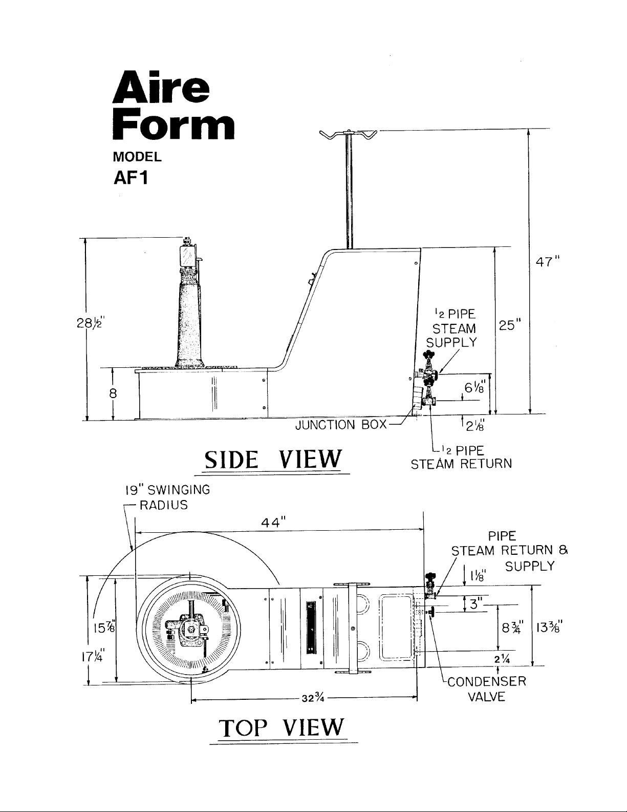
Refer to illustration sheet
(1) UNCRATE MACHINE. Check the nameplate voltage and current, making sure it
is the same as the supply voltage and current.
(2) SET MACHINE IN POSITION.
(3) REMOVE THE REVOLVING FORM by holding the turning knob and the oppo-
site weight “bucket” and lifting approximately 22”.
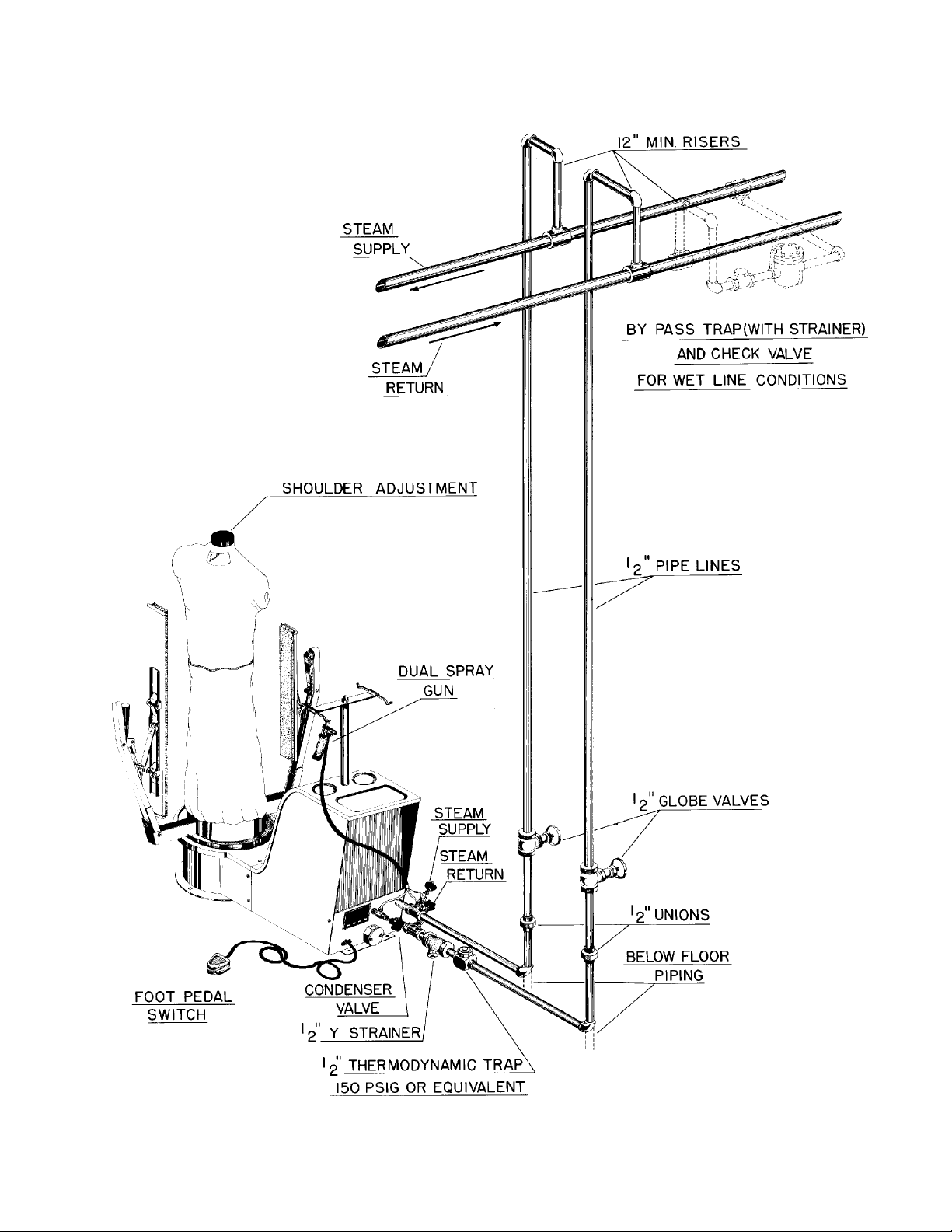
(4) CONNECT STEAM SUPPLY LINE as shown on next page.
(5) CONNECT RETURN LINE as shown on next page.
NOTE: Before final return line connection is made, open the steam supply valve
and blow all foreign matter out of the steam lines and chamber. Failure
to do so will cause trap to leak.
ALLAALLA
ALLA
ALLAALLA
TIONTION
TION
TIONTION
(6) MAKE ELECTRICAL CONNECTIONS in 3” junction box on rear of the machine,
according to applicable electric codes. Connections should include a fused
disconnect switch or circuit breaker with “slo-blow” characteristics and be
capable of carrying 15 amps 115 volts or 8 amps 230 volts.
(7) TURN ON ELECTRICAL POWER AND TEST THE MACHINE.
Replace the revolving assembly, remove the plastic protective bag, and open the
return and steam lines.
Page 4Page 4
Page 4
Page 4Page 4
Page 5Page 5
Page 5
Page 5Page 5

AIRE FORM OPERAAIRE FORM OPERA
AIRE FORM OPERA
AIRE FORM OPERAAIRE FORM OPERA
On the front panel of unit, set timers for required cycle. (Preferred is 5 seconds steam; 10
seconds air).
NOTE: A toggle switch on the control panel may be set to give steam followed by air (AUTO).
Set timers switches as described above. Or you may give air only (ON). Most fabrics
will finish better with the Auto cycle.
Where possible, perform all touc h-up of sleeves, collars, trim, etc., prior to finishing on the Aire
Form. In this way, differences in sheen will be eliminated from the garment.
TING INSTRUCTIONSTING INSTRUCTIONS
TING INSTRUCTIONS
TING INSTRUCTIONSTING INSTRUCTIONS
OPERAOPERA
OPERA
OPERAOPERA
1. Place overbag on the form.
2. Position garment on form and adjust shoulders. A knob on top of the form is used to adjust
the form shoulder width. Turn knob clockwise to increase shoulder width.
3. Step on foot switch to activate the automatic cycle.
4. Remove garment from form.
GENERAL SUGGESTIONS:GENERAL SUGGESTIONS:
GENERAL SUGGESTIONS:
GENERAL SUGGESTIONS:GENERAL SUGGESTIONS:
To finish coats and other open front garments, use front paddle clamp to hold front of garment
in place. Use the hand vent clamps to hold rear vent or pleat.
When additional moisture is needed for hard set wrinkles, use the water spray gun, spraying
into the steam from a distance of approximately 15”. Rotate the garment to the spray gun,
using the turning knob on the revolving assembly.
TION INSTRUCTIONS FOR TION INSTRUCTIONS FOR
TION INSTRUCTIONS FOR
TION INSTRUCTIONS FOR TION INSTRUCTIONS FOR
(Machine can be operated from either side)
““
AIRE”AIRE”
“
AIRE”
““
AIRE”AIRE”
FORM FINISHER FORM FINISHER
FORM FINISHER
FORM FINISHER FORM FINISHER
Keep the nylon bag clean and in good repair. A vacuum cleanable air filter is provided to help
keep the bag clean. Vacuum clean the filter weekly. Remove nylon bag (see detailed instructions) and wet clean as required. Repair holes or worn spots. To obtain proper characteristics
of cloth porosity, bag size, and control strings, use only genuine Cissell replacement bags.
Page 6Page 6
Page 6
Page 6Page 6

NET OVERBAG FOR CISSELL STEAM-AIR FINISHERNET OVERBAG FOR CISSELL STEAM-AIR FINISHER
NET OVERBAG FOR CISSELL STEAM-AIR FINISHER
NET OVERBAG FOR CISSELL STEAM-AIR FINISHERNET OVERBAG FOR CISSELL STEAM-AIR FINISHER
This overbag is for use ONLY when finishing sweaters or other soft garments that do
not require bag contact for proper finishing.
DO NOT use overbag with hard fabrics or heavy garments. Hard set wrinkles will not
be removed when using the overbag.
The Cissell overbag holds the form to a narrow size, thereby spreading steam and
gentle diffused air throughout the garment to eliminate distortion.
THE NET OVERBAG IS EASY THE NET OVERBAG IS EASY
THE NET OVERBAG IS EASY
THE NET OVERBAG IS EASY THE NET OVERBAG IS EASY
1. Place the net bag over the form so that it fully covers the standard nylon bag.
2. Place the garment on the form and operate the machine per standard instructions,
using “large size” setting for faster drying.
In general, garments including bonded knits and wool dresses can be finished without
the overbag.
When ordering additional net overbags, specify F816.
TT
O USEO USE
T
O USE
TT
O USEO USE
Page 7Page 7
Page 7
Page 7Page 7
TT
O REMOVE BAGO REMOVE BAG
T
O REMOVE BAG
TT
O REMOVE BAGO REMOVE BAG
TT
O REPLACE BAGO REPLACE BAG
T
O REPLACE BAG
TT
O REPLACE BAGO REPLACE BAG
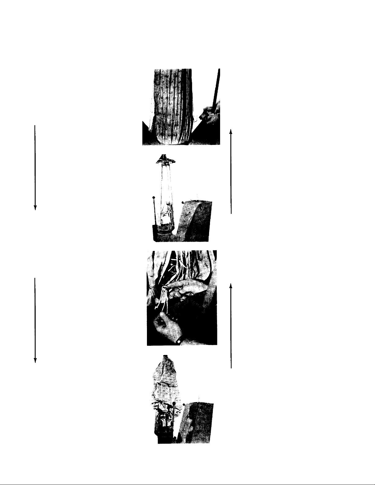
(1) Remove yellow
weights, 1 each
side.
(2) Raise the lower
control ring (inside
bag).
(3) Open zipper and
untie bottom string.
(4) Replace yellow
weights, one each
side, on end of
control strings.
(3) Lower the control
ring inside bag.
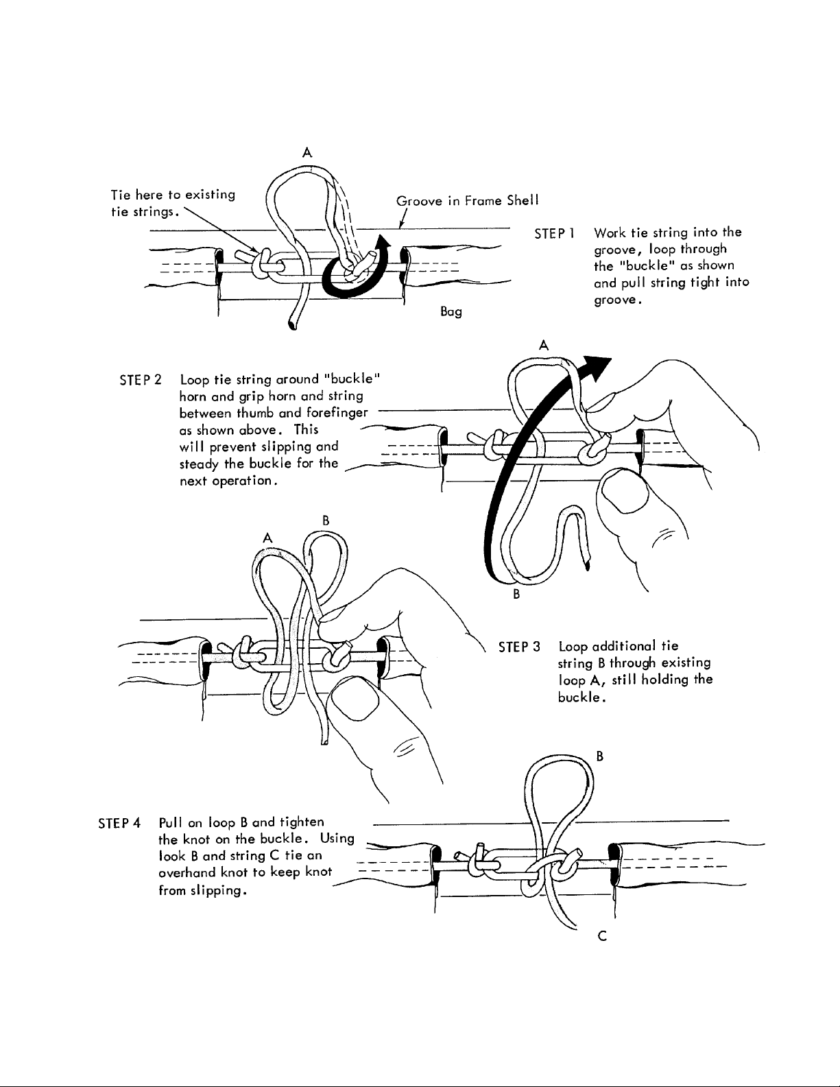
(2) Tie bottom string in
groove and close
zipper. Refer to
instructions on next
page for proper knot
when tying string.
Straighten bag until
control strings are at
the sides.
(4) Lift bag off over
revolving assembly
shoulder form.
Page 8Page 8
Page 8
Page 8Page 8
(1) Place bag over
revolving assembly
shoulder form, with
front of bag toward
front of form.
Page 9Page 9
Page 9
Page 9Page 9

CISSELL FORM FINISHERCISSELL FORM FINISHER
CISSELL FORM FINISHER
CISSELL FORM FINISHERCISSELL FORM FINISHER
INSTRUCTIONS FOR ADJUSTING HEIGHT OR REVOLVING FORM
Should the revolving form “drag” on the Form Finisher base rather than turn freely, the form
must be raised.
Conversely, if the revolving form rides too high above the Form Finisher base, permitting steam
to escape from the space between the form and base, the form must be lowered.
WHEN AN ADJUSTMENT MUST BE MADE, REMOVE REVOLVING FORM BY SIMPLY
LIFTING IT SRAIGHT UP OFF THE FORM FINISHER BASE
PROBLEM: Revolving Form “drags” on base of Form Finisher
TO CORRECT: Loosen F-286 Bearing Lock Nut. Turn F-287 Bearing Adjustment Screw
COUNTER-CLOCKWISE.
CHECK ADJUSTMENT: Replace revolving form on Form Finisher base. Rotate form. If
perfectly adjusted, form will rotate freely and snugly on felt seal around top of base. If form is
still too low...or too high...repeat adjustment until it is correct.
PROBLEM: Revolving Form rides too high above Form Finisher base.
TO CORRECT: Loosen F-286 Bearing Lock Nut. Turn F-287 Bearing Adjustment Screw
CLOCKWISE.
CHECK ADJUSTMENT: Replace revolving form on Form Finisher base. Rotate form. If
perfectly adjusted, form will rotate freely and snugly on felt seal around top of base. If form is
still too high...or too low...repeat adjustment until it is correct.
Page 10Page 10
Page 10
Page 10Page 10

F517 - Adjustable Shoulder Assembly
Consists of 1-10, 18, 19, 20.
AIR FORM REVOLAIR FORM REVOL
AIR FORM REVOL
AIR FORM REVOLAIR FORM REVOL
AF115 - Revolving Form w/Front & Rear Clamps
AF181 - Revolving Form w/o Clamps
Ref.Ref.
Ref.
Ref.Ref.
No.No.
No.
No.No.
1 TU3478 #8 x 1/2” Screw
2 F381 Shoulder Adjustment Rod,
3 F49 Shoulder Lever Pin
4 F192 Insulating Gskt.
5 F492 Neck Form w/4 Bolts,
6 F493 Shoulder Extension
7 F336 Shoulder Connecting Link
8 F494 Bearing Plate w/Scrs.
9 F197 Shldr. Tension Sprg.
10 F317 Shoulder Lever
11 AF113 Frame Assm. w/Hdwe.
12 AF121WH Rear Paddle Clmp. Asm.
13 AF176WH Front Paddle Clmp. Asm.
14 F1060 Bearing Assy.
16 AF207 Collar
17 AF153 Form Assembly
18 TU3477 #10 - 24 x 1/2 Screw
19 FB187 #10 Lockwasher (pkg. 6)
20 FB185 #10 Nut (pkg. 6)
PP
artart
P
art
PP
artart
No.No.
No.
No.No.
VING FORMVING FORM
VING FORM
VING FORMVING FORM
DescriptionDescription
Description
DescriptionDescription
Knob, & Pin
(2 required)
Nuts & Washers
*
*
AF114 Replacement Bag
(not shown)
*See Separate Page for Exploded View
Painted parts furnished in white unless
otherwise specified
Page 11Page 11
Page 11
Page 11Page 11

FRONT PFRONT P
FRONT P
FRONT PFRONT P
REAR PREAR P
REAR P
REAR PREAR P
ADDLE CLAMP ADDLE CLAMP
ADDLE CLAMP
ADDLE CLAMP ADDLE CLAMP
ADDLE CLAMP ADDLE CLAMP
ADDLE CLAMP
ADDLE CLAMP ADDLE CLAMP
ASSEMBLASSEMBL
ASSEMBL
ASSEMBLASSEMBL
ASSEMBLASSEMBL
ASSEMBL
ASSEMBLASSEMBL
Y - Y -
Y -
Y - Y -
Y - Y -
Y -
Y - Y -
AF176AF176
AF176
AF176AF176
AF121AF121
AF121
AF121AF121
Ref.Ref.
Ref.
Ref.Ref.
No.No.
No.
No.No.
1 FG135 Handle Weldment
2 AF157 Trigger Release w/Rodhinge, Pin,
3 F218 Clamp Leaf Spring w/Hardware
4 F267 Pivot Pin w/”E” Rings
5 F240 Clamp Slide Supp. Pin
6 FG443 Clamp Latch Rod
7 F243 Slide Spring Clip
8 F237 Clamp Slide
9 F215 Set Collar
10 F197 Spring
11 F949 Pin
12 FG288 Pin
PP
artart
P
art
PP
artart
No.No.
No.
No.No.
FG450 Latch Pin
F489 “E” Rings
DescriptionDescription
Description
DescriptionDescription
“E” Rings
Painted parts furnished in white unless otherwise specified
Page 12Page 12
Page 12
Page 12Page 12
Ref.Ref.
Ref.
Ref.Ref.
No.No.
No.
No.No.
13 FG277 Stud
14 F63 Springs w/Hardware (Set of 2)
15 F11 No. 11 Sleevers (Set of 2)
16 F432 Front Paddle Channel
17 F433 Sponge for Front Paddle
18 AF165 Sponge for Rear Paddle
19 AF168 Rear Paddle Channel
20 F904 Sponge Pad (Set 6/F842)
21 F842 Vent Clamp
22 F24 No. 24 Sleevers
23 TU4787 Hex Nut
24 F888 “E” Rings
25 F901 #10-24 x 3/8 Screw
26 FB187 #10 Lockwasher
PP
artart
P
art
PP
artart
No.No.
No.
No.No.
DescriptionDescription
Description
DescriptionDescription

AIRE FORM JAIRE FORM J
AIRE FORM J
AIRE FORM JAIRE FORM J
ACKETACKET
ACKET
ACKETACKET
Ref.Ref.
Ref.
Ref.Ref.
No.No.
No.
No.No.
1 AF120 Gun Support Bracket
2 AF117 Locating Plug
3 PU47 Shaft
4 AF152 Tube Cover
5 AF102 Removable Air Filter
6 AF104 Frame Weldment
7 AF103 Filter Screen
9 AF144 Ja cket Weldment
10 FG344 Speed Nut
11 TU8013 Cissell Nameplate
12 AF161 Control Panel Assembly
13 FG343 Screw w/Wear Washer
14 FG345 Retaining Washer
Painted parts furnished in white unless otherwise specified
PP
artart
P
art
PP
artart
No.No.
No.
No.No.
Page 13Page 13
Page 13
Page 13Page 13
DescriptionDescription
Description
DescriptionDescription
(See Separate Page)

CONTROL PCONTROL P
CONTROL P
CONTROL PCONTROL P
ANEL - ANEL -
ANEL -
ANEL - ANEL -
AF161AF161
AF161
AF161AF161
Ref.Ref.
Ref.
Ref.Ref.
No.No.
No.
No.No.
1 FG235 Relay - 115V/50-60 Hz.
2 FG453 Timer - 115-230V
3 AF185 Toggle Switch
4 AF162 Panel
5 AF100 Nameplate
6 PT118 Timer Knob
7 C196 Set Screw
8 LB291 #6-32 x 3/8 Rd. Hd. Screw
PP
artart
P
art
PP
artart
No.No.
No.
No.No.
FG234 Relay - 230V/50-60 Hz.
AF203 Wiring Harness (not shown)
AF216 Resistor, 200VL w/Piggy Back End & Black Insulation
AF217 Resistor, 500VL w/Piggy Back End & Black Insulation
DescriptionDescription
Description
DescriptionDescription
Page 14Page 14
Page 14
Page 14Page 14

AIR FORM REAR BASEAIR FORM REAR BASE
AIR FORM REAR BASE
AIR FORM REAR BASEAIR FORM REAR BASE
Ref.Ref.
Ref.
Ref.Ref.
No.No.
No.
No.No.
PP
artart
P
art
PP
artart
No.No.
No.
No.No.
1 FG274 1/2” Pipe 30” Long
2 SGV13 Supply Valve
3 SGV40 Return Valve
4 AF124 Rear Base Weldment
5 SB170 Junction Box Cover
6 PIU94 Nameplate
7 F739 Solenoid - 115V
F738 Solenoid - 230V
8 TU3549 Rubber Bumper
9 FG175 Rod Extension
DescriptionDescription
Description
DescriptionDescription
Painted parts furnished in white unless otherwise specified
Page 15Page 15
Page 15
Page 15Page 15
Ref.Ref.
Ref.
Ref.Ref.
No.No.
No.
No.No.
10 F520 Seal Spring
11 F519 Nylon Seal
12 AF128 Damper
13 OP296 1/2” Pipe 5” Long
14 FG273 1/2” Pipe 28 - 1/2” Long
15 OP306 Tee - 1/2” x 1/2” x 3/8”
16 FG143 Tee - 1/2” x 1/2” x 1/4”
17 M155 Strain Relief
18 RC385 Round Head Screw
19 M263 Sheet Metal Screw
PP
artart
P
art
PP
artart
No.No.
No.
No.No.
DescriptionDescription
Description
DescriptionDescription

Ref.Ref.
Ref.
Ref.Ref.
No.No.
No.
No.No.
PP
artart
P
art
PP
artart
No.No.
No.
No.No.
DescriptionDescription
Description
DescriptionDescription
Ref.Ref.
Ref.
Ref.Ref.
No.No.
No.
No.No.
PP
artart
P
art
PP
artart
No.No.
No.
No.No.
DescriptionDescription
Description
DescriptionDescription
1 F149 Steam Valve Pull Rod
2 FG320 Extension Bar
3 F215 Set Collar, 2 req’d
4 FG275 Steam Valve Lever Ass’y
5 TU49 Delrin Bearing (Pkg. 2)
6 F539 Stm. Chamber
7 TU4593 1/2” x 90º Pipe Elbow
8 LB20 1/2” Pipe Nipple 3” Long
9 FG319 Stm. Coil Adapter
10 F357 Felt Air Seal
11 FG321 Steam Manifold
12 FG322 Steam Coil
13 FG323 Shallow Base Welded Ass’y
Page 16Page 16
Page 16
Page 16Page 16
14 ------ See Separate Parts Sheet
15 F122 1/4” - 28 Brass Nut
16 RC349 1/4” Lockwasher
17 V02 1/16” x 1/2” Cotter Pin
18 IB139 3/8” x 1-1/4” Hex. Hd. Scw.
19 VSB134 3/8” Split Lockwasher
20 IB140 3/8” Flat Washer
21 F819 5/16” - 18-5/8” Sq. Hd. Set Scw.
22 P126 1/4” - 20 x 1/4” Set Scw.
23 TU3210 5/16” - 18 x 5/8” Hex. Scw.
24 TU2814 5/16” Split Lockwasher
25 TU2793 #8 x 5/8” S.M.S.

Ref.Ref.
Ref.
Ref.Ref.
No.No.
No.
No.No.
PP
artart
P
art
PP
artart
No.No.
No.
No.No.
1 F287 Bearing Adjustment Scr.
2 F286 Bearing Locknut
3 F285 Bearing Support Box
4 FV101 Valve Lever
5 OP547 Locknut
6 FV106 Collar Retainer
7 F18 Steam Spreader
FV110 Valve Ass’y CONSISTS OF
10 FV100 Valve Body
11* V36 Valve Seat
12* P103 Gasket
13 F359 “E” Ring
14* FV103 Valve Stem
15* V15 Small Locknut
16* V16 Teflon Disc
17 FV104 Valve Disc Holder
18* V330 30 Lb. Spring
19 FV105 Spring Retainer
20* F358 “E” Ring
*K451 Repair Kit for FV110 Valve
DescriptionDescription
Description
DescriptionDescription
REF. NO. 10-20
Page 17Page 17
Page 17
Page 17Page 17

CONDENSER PCONDENSER P
CONDENSER P
CONDENSER PCONDENSER P
SGC9 - Condenser Only (Consists of Ref. Nos. 2, 3, 4, 5, 6)
ARTSARTS
ARTS
ARTSARTS
Ref.Ref.
Ref.
Ref.Ref.
No.No.
No.
No.No.
1 F578 Plug
2 SGC6 Upper Section
3 SG116 Taptite Bolts
4 SG77 “O” Ring
5 SG79 Strainer
6 SGC8 Lower Section
7 OP225 Straight Connector
8 FG340 Copper Tube - 24”
9 FG159 Elbow
10 OP305 Bushing 3/8 x 1/4
11 BR61 Bushing 1/4 x 1/8
12 SB88 Straight Connector
13 AF142 Tube - 16”
14 V63 Small Pack Nut
15 PU8 Bead
16 SGV12 Valve
PP
artart
P
art
PP
artart
No.No.
No.
No.No.
Page 18Page 18
Page 18
Page 18Page 18
DescriptionDescription
Description
DescriptionDescription

BLOWER & MOBLOWER & MO
BLOWER & MO
BLOWER & MOBLOWER & MO
TT
OR MOUNTOR MOUNT
T
OR MOUNT
TT
OR MOUNTOR MOUNT
Ref.Ref.
Ref.
Ref.Ref.
No.No.
No.
No.No.
1 FG292 Blower Wheel
2 FG226 Inlet Cone
3 AF131 Motor Bracket w/Hardware (7, 8, 9)
4 AF130 Mounting Hardware (3 sets/pkg.)
5 FG148 Harness Clamp
6 MTR88 Motor - 110-120/220-240/50/60/1
7 FB124 Cap Screw
8 TU2814 Split Lockwasher
9 C249 Hex Nut
10 TU2793 Sheet Metal Screw
11 M263 Sheet Metal Screw
PP
artart
P
art
PP
artart
No.No.
No.
No.No.
Consult factory for other voltages
Page 19Page 19
Page 19
Page 19Page 19
DescriptionDescription
Description
DescriptionDescription

FOOFOO
FOO
FOOFOO
T PEDAL SWITCH T PEDAL SWITCH
T PEDAL SWITCH
T PEDAL SWITCH T PEDAL SWITCH
ASSEMBLASSEMBL
ASSEMBL
ASSEMBLASSEMBL
Y - PT527Y - PT527
Y - PT527
Y - PT527Y - PT527
INSTINST
INST
INSTINST
ALLAALLA
ALLA
ALLAALLA
FOR FOR
FOR
FOR FOR
1. Turn switch to upside down
2. Lift off base plate pad.
3. Remove two (2) screws marked (B)
4. Remove two (2) washers, plate,
insulation and switch.
5. Remove wires from old switch and
6. Reinstall switch, insulation, plate,
TION INSTRUCTIONTION INSTRUCTION
TION INSTRUCTION
TION INSTRUCTIONTION INSTRUCTION
AF 177 SWITCHAF 177 SWITCH
AF 177 SWITCH
AF 177 SWITCHAF 177 SWITCH
position and remove two (2)
screws marked (A) as illustrated.
as shown.
install wires on new switch and
tighten securely.
washers and screws and tighten
securely.
Page 20Page 20
Page 20
Page 20Page 20
7. Reinstall base-plate-pad and
screws and tighten securely.

SPRASPRA
SPRA
SPRASPRA
Y GUN Y GUN
Y GUN
Y GUN Y GUN
VV
V
VV
ALAL
AL
ALAL
VE PVE P
VE P
VE PVE P
ARTSARTS
ARTS
ARTSARTS
Ref.Ref.
Ref.
Ref.Ref.
No.No.
No.
No.No.
10 SGV47 Valve Spring
PP
artart
P
art
PP
artart
No.No.
No.
No.No.
1 SGV38 Valve Pin
2 SGV41 Hose Adapter
3 SGV37 Teflon Ball
4 SGV56 Valve Body
5 V30 Small Pack Ring
6 SGV46 Piston
7 V73 Control Knob Asy.
8 SGV56 Valve Body
9 SGV57 Valve Body
DescriptionDescription
Description
DescriptionDescription
Page 21Page 21
Page 21
Page 21Page 21

DUDU
AL SPRAAL SPRA
DU
AL SPRA
DUDU
AL SPRAAL SPRA
SG146 - Complete Gun & Hose SG146 - Complete Gun & Hose
SG146 - Complete Gun & Hose
SG146 - Complete Gun & Hose SG146 - Complete Gun & Hose
Y GUN & HOSE Y GUN & HOSE
Y GUN & HOSE
Y GUN & HOSE Y GUN & HOSE
SG147 - Dual Spray Gun Only
SKD147 - Repair Kit-Includes parts marked (*).
ASSEMBLASSEMBL
ASSEMBL
ASSEMBLASSEMBL
AssemblyAssembly
Assembly
AssemblyAssembly
Parts to repair one Dual Spray Gun.
YY
Y
YY
SG148 - Hose SG148 - Hose
SG148 - Hose
SG148 - Hose SG148 - Hose
Ref.Ref.
Ref.
Ref.Ref.
No.No.
No.
No.No.
1 SG122 Tube Adapter
2 SG136 Set of 3 Tubes (Black, White,
3 SG11 Tube Connection Nut
4 SG126 Tube Connector
5 SG25 Hose Gasket
6 SG137 Tube Cover Assembly
7 AF123 Hose Clamp (Not part
PP
P
PP
No.No.
No.
No.No.
SG200 Blue Tube Only
SG201 Black Tube Only
SG202 White Tube Only
Assembly OnlyAssembly Only
Assembly Only
Assembly OnlyAssembly Only
artart
art
artart
DescriptionDescription
Description
DescriptionDescription
& Blue)
of Assembly)
Page 22Page 22
Page 22
Page 22Page 22

HOSE CONNECTIONS FORHOSE CONNECTIONS FOR
HOSE CONNECTIONS FOR
HOSE CONNECTIONS FORHOSE CONNECTIONS FOR
CISSELL DUCISSELL DU
CISSELL DU
CISSELL DUCISSELL DU
AL SPRAAL SPRA
AL SPRA
AL SPRAAL SPRA
Y GUNY GUN
Y GUN
Y GUNY GUN
* NOTE: This connection works best in most installations. Should there be excessive condensate in the
spray, reverse these two connections and use the configuration that has the best results.
Page 23Page 23
Page 23
Page 23Page 23

TT
O O
ADJUST STEAM ADJUST STEAM
T
O
ADJUST STEAM
TT
O O
ADJUST STEAM ADJUST STEAM
1. Set steam valve extension bar and solenoid lever at 90º as shown and tighten set screw.
2. Adjust steam valve adjusting nuts until 1/32” to 1/16” gap is obtained as shown
above and lock adjusting nuts tightly together.
VV
V
VV
ALAL
AL
ALAL
VE VE
AND SOLENOID LINKAGE:AND SOLENOID LINKAGE:
VE
AND SOLENOID LINKAGE:
VE VE
AND SOLENOID LINKAGE:AND SOLENOID LINKAGE:
Page 24Page 24
Page 24
Page 24Page 24

Page 25Page 25
Page 25
Page 25Page 25

Page 26Page 26
Page 26
Page 26Page 26

PROBLEMPROBLEM
PROBLEM
PROBLEMPROBLEM
(1) No Steam
(2) Blower motor will start,
steam won’t start
(3) Leaking steam valve
(4) Wet steam
CACA
USEUSE
CA
USE
CACA
USEUSE
1A Steam supply valve
off.
1B Electric power “Off”
2A Loose wires
2B Incorrect voltage of
electrical parts
2C Defective start switch
2D Defective solenoid
2E Defective solenoid
linkage
3A Solenoid linkage
adjusted incorrectly
3B Loose valve seat
3C Worn valve
4A Trap not operating
4B Trap installed
incorrectly
4C Check valve installed
wrong or sticking
REMEDYREMEDY
REMEDY
REMEDYREMEDY
Open valve in steam supply
line.
Inspect electric service for
blown fuses & loose connections. Turn main disconnect
“ON”.
Inspect and replace any loose
wires.
Inspect nameplate voltage and
voltage on electrical parts,
especially the solenoid. Replace
switch if necessary.
Check switch to see that it
operates and will carry current.
Replace switch if necessary.
Inspect solenoid. Replace if
necessary.
Check linkage between solenoid
and steam valve for broken or
loose parts. Repair or replace
as required. (See adjustment
instructions.)
Inspect linkage and adjust
according to instructions.
Tighten all lock nuts and set
screws.
Inspect and tighten seat if
required.
Inspect valve parts. Replace
worn parts as required.
Check size and operation of
trap. Repair or replace if
required.
Check to see that direction of
flow in trap is correct and that
trap is in or below machine
return line.
Check to see that direction of
flow is correct and valve not
sticking.
Page 27Page 27
Page 27
Page 27Page 27

PROBLEMPROBLEM
PROBLEM
PROBLEMPROBLEM
(4) Wet steam (Cont.)
(5) Water accumulates in
base
(6) Excessive noise or
vibration
(7) Blower motor won’t
start, machine won’t
steam
CACA
USEUSE
CA
USE
CACA
USEUSE
4D Strainer clogged
4E Return line turned off
4F Steam Cycle too long
4G Improperly installed
steam lines
4H Heavy condensate in
supply line
4I Machine not
individually trapped
4J Back pressure in return
line
5A Steam too wet
5B Leak in finned tube or
pipe fitting
5C Leaking steam valve
6A Foreign object in blower
wheel
6B Blower wheel out of
balance
6C Motor bearings bad
6D Motor mount bent
6E Blower wheel loose on
motor shaft
7A No electrical power
REMEDYREMEDY
REMEDY
REMEDYREMEDY
Inspect strainer and clean if
necessary.
Open valve in condensate
return line.
Reduce amount of time set on
steam timer.
Check steam line installation to
see that “risers” are installed,
as shown on installation
illustration.
Install a by-pass trap from
supply header to by-pass
condensate to return line.
Install a separate trap for each
machine.
Inspect all traps to see if one is
stuck open, or improperly
installed. Perform steps necessary to make return line drain
by gravity to condensate return
tank. See that return tank is
adequately vented.
See wet steam above.
Inspect machine and repair or
replace any leaking parts.
See leaking steam valve (3).
Inspect wheel and remove any
foreign objects & lint.
Inspect wheel for loose balance
weights, out of round or damage, replace if necessary.
Inspect motor to see if bearings
are tight and motor free
turning. Replace motor if
necessary.
Inspect motor mount to see if
machine has been dropped in
transit, bending the mount,
letting the blower wheel hit the
housing. If so, inspect blower
wheel for damage. Replace
either or both if necessary.
Check to see that wheel is
mounted in center of housing,
key is in keyway if used, and
both set screws tight.
Check electrical service and be
sure main switch is “ON” all
wires are tight and fuses are
good.
Page 28Page 28
Page 28
Page 28Page 28

PROBLEMPROBLEM
PROBLEM
PROBLEMPROBLEM
(7) Blower motor won’t
start, machine won’t
steam (Cont.)
(8) Blower motor won’t
start, machine steams
continuously after air
switch is operated.
(9) Blower motor will start,
machine steams only
while control knob is
pushed
CACA
USEUSE
CA
USE
CACA
USEUSE
7B Incorrect supply voltage
7C Air timer set at 0 time
7D Defective blower relay
7E Defective blower motor
7F Loose wires
8 Defective start switch
9A Steam timer set at 0
time
9B Defective steam timer
9C Defective steam relay
REMEDYREMEDY
REMEDY
REMEDYREMEDY
Check power source. Voltage
phase and frequency must be
the same as specified on machine nameplate.
Timer knob may slip on the
shaft and leave the timer set at
0 time. Tighten knob set screw
and set timer and knob to suit,
approx. 20 seconds.
Check to see if the blower relay
will operate. If not, replace
relay.
Check motor to see if it will
operate on normal nameplate
electrical power. If not, replace
the motor.
Check to see that all wires and
connections are tight. If not,
replace the wires and tighten
connections.
Check switch to see that it
operates and will carry current.
Replace switch if necessary.
Timer knob may slip on the
shaft and leave the timer set at
0 time. Tighten knob set screw
and set timer and knob to suit,
approx. 8 seconds.
Check timer operation. See if
timer switch operates properly.
If not, replace timer.
Check to see if relay will
operate on rated current and if
contacts will carry current. If
not, replace relay.
Page 29Page 29
Page 29
Page 29Page 29

PROBLEMPROBLEM
PROBLEM
PROBLEMPROBLEM
(10) Inadequate steam flow
(11) Blower motor will start,
steam starts but won’t
stop
(12) Blower Motor won’t
stop
CACA
USEUSE
CA
USE
CACA
USEUSE
10A Steam valve linkage not
properly adjusted
10B Steam time set too
short
11 Defective steam timer
12A Defective Air timer
12B Defective blower relay
REMEDYREMEDY
REMEDY
REMEDYREMEDY
Adjust linkage according to
adjustment instructions.
Tighten all set screws and lock
nuts.
Set steam timer for longer time.
Tighten knob set screw if
necessary.
Check timer operation. See if
timer switch operates properly.
If operation is not correct,
replace the timer.
Check timer operation. See if
timer switch operates properly.
If operation is not correct,
replace the timer.
Check to see if relay operates
properly on rated current. If
contacts are stuck or welded
shut, or relay does not operate
properly, replace it.
Aire FAire F
Aire F
Aire FAire F
orm orm
orm
orm orm
PP
artart
P
art
PP
artart
No.No.
No.
No.No.
F218 Clamp Leaf Spring
F267 Pivot Pin w/”E” Rings
F63 Covered Spring Asm.
F11 Set No. 11 Sleevers
F433 Sponge for Front Paddle
AF165 Sponge for Rear Paddle
F904 Foam Rubber Pads, Vent Clamp
F357 Felt Air Seal
F287 Bearing Adjust Screw
F18 Steam Spreader Asm.
F739H Solenoid
F738H Solenoid
V30 Pack Ring
TU13224 RBM Relay, 115V
TU13225 RBM Relay, 230V
FG453 Timer
AF185 Toggle Switch
AF102 Air Filter
SKD147 Repair Kit for SG147 Gun
SG148 Teflon Hose Assy. for SG147
K451 Repair Kit for FV110 Valve
AF1 Suggested Spare PAF1 Suggested Spare P
AF1 Suggested Spare P
AF1 Suggested Spare PAF1 Suggested Spare P
DescriptionDescription
Description
DescriptionDescription
artsarts
arts
artsarts
Page 30Page 30
Page 30
Page 30Page 30
 Loading...