

Page 1

Cisco 850 Series and Cisco 870 Series Access Routers Hardware Installation Guide
Corporate Headquarters
Cisco Systems, Inc.
170 West Tasman Drive
San Jose, CA 95134-1706
USA
http://www.cisco.com
Tel: 408 526-4000
800 553-NETS (6387)
Fax: 408 526-4100
Text Part Number: OL-5331-01
Page 2

CCSP, the Cisco Square Bridge logo, Follow Me Browsing, and StackWise are trademarks of Cisco Systems, Inc.; Changing the Way We Work, Live, Play, and Learn, and iQuick
Study are service marks of Cisco Systems, Inc.; and Access Registrar, Aironet, ASIST, BPX, Catalyst, CCDA, CCDP, CCIE, CCIP, CCNA, CCNP, Cisco, the Cisco Certified
Internetwork Expert logo, Cisco IOS, Cisco Press, Cisco Systems, Cisco Systems Capital, the Cisco Systems logo, Cisco Unity, Empowering the Internet Generation,
Enterprise/Solver, EtherChannel, EtherFast, EtherSwitch, Fast Step, FormShare, GigaDrive, GigaStack, HomeLink, Internet Quotient, IOS, IP/TV, iQ Expertise, the iQ logo, iQ
Net Readiness Scorecard, LightStream, Linksys, MeetingPlace, MGX, the Networkers logo, Networking Academy, Network Registrar, Pac ke t, PIX, Post-Routing, Pre-Routing,
ProConnect, RateMUX, ScriptShare, SlideCast, SMARTnet, StrataView Plus, SwitchProbe, TeleRouter, The Fastest Way to Increase Your Internet Quotient, TransPath, and VCO
are registered trademarks of Cisco Systems, Inc. and/or its affiliates in the United States and certain other countries.
All other trademarks mentioned in this document or Website are the property of their respective owners. The use of the word partner does not imply a partnership relationship
between Cisco and any other company. (0501R)
THE SPECIFICATIONS AND INFORMATION REGARDING THE PRODUCTS IN THIS MANUAL ARE SUBJECT TO CHANGE WITHOUT NOTICE. ALL
STATEMENTS, INFORMATION, AND RECOMMENDATIONS IN THIS MANUAL ARE BELIEVED TO BE ACCURATE BUT ARE PRESENTED WITHOUT
WARRANTY OF ANY KIND, EXPRESS OR IMPLIED. USERS MUST TAKE FULL RESPONSIBILITY FOR THEIR APPLICATION OF ANY PRODUCTS.
THE SOFTWARE LICENSE AND LIMITED WARRANTY FOR THE ACCOMPANYING PRODUCT ARE SET FORTH IN THE INFORMATION PACKET THAT
SHIPPED WITH THE PRODUCT AND ARE INCORPORATED HEREIN BY THIS REFERENCE. IF YOU ARE UNABLE TO LOCATE THE SOFTWARE LICENSE
OR LIMITED WARRANTY, CONTACT YOUR CISCO REPRESENTATIVE FOR A COPY.
The following information is for FCC compliance of Class A devices: This equipment has been tested and found to comply with the limits for a Class A digital device, pursuant
to part 15 of the FCC rules. These limits are designed to provide reasonable protection against harmful interference when the equipment is operated in a commercial
environment. This equipment generates, uses, and can radiate radio-frequency energy and, if not installed and used in accordance with the instruction manual, may cause
harmful interference to radio communications. Operation of this equipment in a residential area is likely to cause harmful interference, in which case users will be required
to correct the interference at their own expense.
The following information is for FCC compliance of Class B devices: The equipment described in this manual generates and may radiate radio-frequency energy. If it is not
installed in accordance with Cisco’s installation instructions, it may cause interference with radio and television reception. This equipment has been tested and found to
comply with the limits for a Class B digital device in accordance with the specifications in part 15 of the FCC rules. These specifications are designed to provide reasonable
protection against such interference in a residential installation. However, there is no guarantee that interference will not occur in a particular installation.
Modifying the equipment without Cisco’s written authorization may result in the equipment no longer complying with FCC requirements for Class A or Class B digital
devices. In that event, your right to use the equipment may be limited by FCC regulations, and you may be required to correct any interference to radio or television
communications at your own expense.
You can determine whether your equipment is causing interference by turning it off. If the interference stops, it was probably caused by the Cisco equipment or one of its
peripheral devices. If the equipment causes interference to radio or television reception, try to correct the interference by using one or more of the following measures:
• Turn the television or radio antenna until the interference stops.
• Move the equipment to one side or the other of the television or radio.
• Move the equipment farther away from the television or radio.
• Plug the equipment into an outlet that is on a different circuit from the television or radio. (That is, make certain the equipment and the television or radio are on circuits
controlled by different circuit breakers or fuses.)
Modifications to this product not authorized by Cisco Systems, Inc. could void the FCC approval and negate your authority to operate the product.
The Cisco implementation of TCP header compression is an adaptation of a program developed by the University of California, Berkeley (UCB) as part of UCB’s public
domain version of the UNIX operating system. All rights reserved. Copyright © 1981, Regents of the University of California.
NOTWITHSTANDING ANY OTHER WARRANTY HEREIN, ALL DOCUMENT FILES AND SOFTWARE OF THESE SUPPLIERS ARE PROVIDED “AS IS” WITH
ALL FAULTS. CISCO AND THE ABOVE-NAMED SUPPLIERS DISCLAIM ALL WARRANTIES, EXPRESSED OR
LIMITATION, THOSE OF MERCHANTABILITY, FITNESS FOR A PARTICULAR PURPOSE AND NONINFRINGEMENT OR ARISING FROM A COURSE OF
DEALING, USAGE, OR TRADE PRACTICE.
IN NO EVENT SHALL CISCO OR ITS SUPPLIERS BE LIABLE FOR ANY INDIRECT, SPECIAL, CONSEQUENTIAL, OR INCIDENTAL DAMAGES, INCLUDING,
WITHOUT LIMITATION, LOST PROFITS OR LOSS OR DAMAGE TO DATA ARISING OUT OF THE USE OR INABILITY TO USE THIS MANUAL, EVEN IF CISCO
OR ITS SUPPLIERS HAVE BEEN ADVISED OF THE POSSIBILITY OF SUCH DAMAGES.
IMPLIED, INCLUDING, WITHOUT
Cisco 850 Series and Cisco 870 Series Access Routers Hardware Installation Guide
Copyright © 2005 Cisco Systems, Inc. All rights reserved.
Page 3

Preface 7
Objective 1-7
Audience 1-7
Organization 1-8
Conventions 1-8
Related Documentation 1-14
Obtaining Documentation and Submitting a Service Request 1-14
CONTENTS
CHAPTER
1 Product Overview 1-1
General Descriptions of the Router Models 1-1
Cisco 851 and Cisco 871 Ethernet-to-Ethernet Routers 1-1
Router Ports on the Cisco 851 and Cisco 871 Back Panel 1-3
USB Port Power Allocation on the Cisco 871 Router 1-3
Cisco 857 and Cisco 877 ADSL-over-POTS Routers 1-3
Router Ports on the Cisco 857 and Cisco 877 Back Panel 1-5
Cisco 876 ADSL-over-ISDN Router 1-5
Router Ports on the Cisco 876 Back Panel 1-6
Cisco 878 SHDSL Router 1-6
Router Ports on the Cisco 878 Back Panel 1-7
Feature Summary 1-7
Hardware Features 1-9
Serial Number Location 1-9
LED Indicators on the Routers 1-9
Integrated 802.11b/g Radio Module (Wireless Models Only) 1-11
Supported Cisco Radio Antennas (Wireless Models Only) 1-12
External Power-over-Ethernet Module (Optional) 1-12
LED Indicators on the PoE Module 1-16
Router Memory 1-16
Router Hardware Security 1-17
CHAPTER
OL-5331-01
Regulatory Compliance 1-17
2 Preinstallation Information 2-1
Safety Warnings and Guidelines 2-1
Additional Warnings for Wireless Routers 2-3
Cisco 850 Series and Cisco 870 Series Access Routers Hardware Installation Guide
3
Page 4

Contents
General Safety Guidelines for Wireless Routers 2-3
Preventing Electrostatic Discharge Damage 2-3
Preventing Damage to the Router 2-4
Unpacking the Box 2-4
Preparing for Installation 2-5
What to Do Next 2-6
CHAPTER
CHAPTER
3 Router and PoE Module Mounting Procedures 3-1
Connecting Antennas to the Wireless Router 3-1
Mounting on a Table 3-1
Mounting on a Wall 3-2
Guidelines for Wall Mounting 3-2
Mounting the Router on a Wall 3-2
Mounting the PoE Module on a Wall 3-5
What to Do Next 3-6
4 Router Cabling Procedures 4-1
Cabling for Nonwireless Routers 4-2
Typical Installations 4-2
Connecting the Radio Antennas to the Wireless Router 4-6
Connecting the Power-over-Ethernet Module (Optional) 4-7
Connecting a Server, PC, or Workstation 4-8
Connecting an External Ethernet Switch (Optional) 4-9
Connecting a Broadband Modem 4-11
CHAPTER
4
Connecting a Terminal or PC to the Console Port 4-12
Connecting an Async Modem to the Console Port 4-13
Connecting an ISDN S/T Port 4-14
Connecting an ADSL Line—ADSLoPOTS Port 4-16
Connecting an ADSL Line—ADSLoISDN Port 4-17
Connecting a G.SHDSL Line 4-18
Connecting the AC Adapter 4-19
Verifying Router Operations 4-21
What to Do Next 4-22
5 Initial Configuration 5-1
Installing Cisco Router and Security Device Manager 5-1
Cisco 850 Series and Cisco 870 Series Access Routers Hardware Installation Guide
OL-5331-01
Page 5

Initial Configuration Using Cisco SDM 5-1
Initial Configuration Using the Setup Command Facility 5-2
Initial Configuration Using the Cisco CLI—Manual Configuration 5-4
Verifying the Initial Configuration 5-5
What to Do Next 5-5
Contents
CHAPTER
APPENDIX
I
NDEX
6 Troubleshooting 6-1
Before You Call Your Cisco Reseller 6-1
Problems During First Startup 6-2
Problems After the Router Is Running 6-3
A Specifications A-1
Router Specifications A-1
Power-over-Ethernet Module Specifications A-2
LAN Port Pinouts A-3
Console Connector Pinouts A-4
ADSL Port Connector Pinouts A-4
Cable Specifications A-5
Ethernet Cable Specifications A-5
Maximum Cable Length A-5
OL-5331-01
Cisco 850 Series and Cisco 870 Series Access Routers Hardware Installation Guide
5
Page 6

Contents
Cisco 850 Series and Cisco 870 Series Access Routers Hardware Installation Guide
6
OL-5331-01
Page 7

Preface
This preface describes the objectives, audience, organization, and conventions of this guide, and
describes related documents that have additional information. It contains the following sections:
• Objective, page 7
• Audience, page 7
• Organization, page 8
• Conventions, page 8
• Related Documentation, page 14
Objective
Audience
• Obtaining Documentation and Submitting a Service Request, page 14
This guide explains how to install, maintain, and troubleshoot your router hardware.
This guide describes the wireless and nonwireless Cisco 850 series and Cisco 870 series router models.
Some information may not apply to your particular router model.
For warranty, service, and support information, see the “Cisco One-Year Limited Hardware Warranty
Terms” section in the Cisco 850 Series and Cisco 870 Series Access Routers Cabling and Setup Quick
Start Guide that was shipped with your router.
This guide is intended for service technicians who have little or no experience in installing routers and
whose goal is to connect the router to the network as quickly as possible.
OL-5331-01
Cisco 850 Series and Cisco 870 Series Access Access Routers Hardware Installation Guide
7
Page 8

Organization
Organization
This guide contains the following information:
Chapter 1, “Product Overview” Describes the router hardware and features.
Chapter 2, “Preinstallation Information” Provides preinstallation information, including
Chapter 3, “Router and PoE Module Mounting
Procedures”
Chapter 4, “Router Cabling Procedures” Provides information about connecting the router to
Chapter 5, “Initial Configuration” Provides the procedures for initially configuring the
Chapter 6, “Troubleshooting” Describes problems that might develop and how to
Appendix A, “Specifications” Provides product specifications, port connector
Preface
safety warnings and guidelines, and information
about the items shipped with your router.
Describes how to mount the router before
connecting devices to the router.
various devices, mounting the router, and powering
up the router and the connected devices.
router settings.
identify and solve them.
pinouts, and specifications for cables that you might
need to supply.
Conventions
This section describes the conventions used in this guide.
Note Means reader take note. Notes contain helpful suggestions or references to additional information and
material.
Caution This symbol means reader be careful. In this situation, you might do something that could result in
equipment damage or loss of data.
Cisco 850 Series and Cisco 870 Series Access Access Routers Hardware Installation Guide
8
OL-5331-01
Page 9

Preface
Conventions
Warning
Waarschuwing
Varoitus
IMPORTANT SAFETY INSTRUCTIONS
This warning symbol means danger. You are in a situation that could cause bodily injury. Before you
work on any equipment, be aware of the hazards involved with electrical circuitry and be familiar
with standard practices for preventing accidents. Use the statement number provided at the end of
each warning to locate its translation in the translated safety warnings that accompanied this
device.
Statement 1071
SAVE THESE INSTRUCTIONS
BELANGRIJKE VEILIGHEIDSINSTRUCTIES
Dit waarschuwingssymbool betekent gevaar. U verkeert in een situatie die lichamelijk letsel kan
veroorzaken. Voordat u aan enige apparatuur gaat werken, dient u zich bewust te zijn van de bij
elektrische schakelingen betrokken risico's en dient u op de hoogte te zijn van de standaard
praktijken om ongelukken te voorkomen. Gebruik het nummer van de verklaring onderaan de
waarschuwing als u een vertaling van de waarschuwing die bij het apparaat wordt geleverd, wilt
raadplegen.
BEWAAR DEZE INSTRUCTIES
TÄRKEITÄ TURVALLISUUSOHJEITA
Tämä varoitusmerkki merkitsee vaaraa. Tilanne voi aiheuttaa ruumiillisia vammoja. Ennen kuin
käsittelet laitteistoa, huomioi sähköpiirien käsittelemiseen liittyvät riskit ja tutustu
onnettomuuksien yleisiin ehkäisytapoihin. Turvallisuusvaroitusten käännökset löytyvät laitteen
mukana toimitettujen käännettyjen turvallisuusvaroitusten joukosta varoitusten lopussa näkyvien
lausuntonumeroiden avulla.
Attention
Warnung
SÄILYTÄ NÄMÄ OHJEET
IMPORTANTES INFORMATIONS DE SÉCURITÉ
Ce symbole d'avertissement indique un danger. Vous vous trouvez dans une situation pouvant
entraîner des blessures ou des dommages corporels. Avant de travailler sur un équipement, soyez
conscient des dangers liés aux circuits électriques et familiarisez-vous avec les procédures
couramment utilisées pour éviter les accidents. Pour prendre connaissance des traductions des
avertissements figurant dans les consignes de sécurité traduites qui accompagnent cet appareil,
référez-vous au numéro de l'instruction situé à la fin de chaque avertissement.
CONSERVEZ CES INFORMATIONS
WICHTIGE SICHERHEITSHINWEISE
Dieses Warnsymbol bedeutet Gefahr. Sie befinden sich in einer Situation, die zu Verletzungen führen
kann. Machen Sie sich vor der Arbeit mit Geräten mit den Gefahren elektrischer Schaltungen und
den üblichen Verfahren zur Vorbeugung vor Unfällen vertraut. Suchen Sie mit der am Ende jeder
Warnung angegebenen Anweisungsnummer nach der jeweiligen Übersetzung in den übersetzten
Sicherheitshinweisen, die zusammen mit diesem Gerät ausgeliefert wurden.
BEWAHREN SIE DIESE HINWEISE GUT AUF.
OL-5331-01
Cisco 850 Series and Cisco 870 Series Access Access Routers Hardware Installation Guide
9
Page 10

Conventions
Preface
Avvertenza
Advarsel
Aviso
IMPORTANTI ISTRUZIONI SULLA SICUREZZA
Questo simbolo di avvertenza indica un pericolo. La situazione potrebbe causare infortuni alle
persone. Prima di intervenire su qualsiasi apparecchiatura, occorre essere al corrente dei pericoli
relativi ai circuiti elettrici e conoscere le procedure standard per la prevenzione di incidenti.
Utilizzare il numero di istruzione presente alla fine di ciascuna avvertenza per individuare le
traduzioni delle avvertenze riportate in questo documento.
CONSERVARE QUESTE ISTRUZIONI
VIKTIGE SIKKERHETSINSTRUKSJONER
Dette advarselssymbolet betyr fare. Du er i en situasjon som kan føre til skade på person. Før du
begynner å arbeide med noe av utstyret, må du være oppmerksom på farene forbundet med
elektriske kretser, og kjenne til standardprosedyrer for å forhindre ulykker. Bruk nummeret i slutten
av hver advarsel for å finne oversettelsen i de oversatte sikkerhetsadvarslene som fulgte med denne
enheten.
TA VARE PÅ DISSE INSTRUKSJONENE
INSTRUÇÕES IMPORTANTES DE SEGURANÇA
Este símbolo de aviso significa perigo. Você está em uma situação que poderá ser causadora de
lesões corporais. Antes de iniciar a utilização de qualquer equipamento, tenha conhecimento dos
perigos envolvidos no manuseio de circuitos elétricos e familiarize-se com as práticas habituais de
prevenção de acidentes. Utilize o número da instrução fornecido ao final de cada aviso para
localizar sua tradução nos avisos de segurança traduzidos que acompanham este dispositivo.
¡Advertencia!
Varning!
GUARDE ESTAS INSTRUÇÕES
INSTRUCCIONES IMPORTANTES DE SEGURIDAD
Este símbolo de aviso indica peligro. Existe riesgo para su integridad física. Antes de manipular
cualquier equipo, considere los riesgos de la corriente eléctrica y familiarícese con los
procedimientos estándar de prevención de accidentes. Al final de cada advertencia encontrará el
número que le ayudará a encontrar el texto traducido en el apartado de traducciones que acompaña
a este dispositivo.
GUARDE ESTAS INSTRUCCIONES
VIKTIGA SÄKERHETSANVISNINGAR
Denna varningssignal signalerar fara. Du befinner dig i en situation som kan leda till personskada.
Innan du utför arbete på någon utrustning måste du vara medveten om farorna med elkretsar och
känna till vanliga förfaranden för att förebygga olyckor. Använd det nummer som finns i slutet av
varje varning för att hitta dess översättning i de översatta säkerhetsvarningar som medföljer denna
anordning.
SPARA DESSA ANVISNINGAR
10
Cisco 850 Series and Cisco 870 Series Access Access Routers Hardware Installation Guide
OL-5331-01
Page 11
Preface
Conventions
OL-5331-01
Cisco 850 Series and Cisco 870 Series Access Access Routers Hardware Installation Guide
11
Page 12
Conventions
Preface
Aviso
Advarsel
INSTRUÇÕES IMPORTANTES DE SEGURANÇA
Este símbolo de aviso significa perigo. Você se encontra em uma situação em que há risco de lesões
corporais. Antes de trabalhar com qualquer equipamento, esteja ciente dos riscos que envolvem os
circuitos elétricos e familiarize-se com as práticas padrão de prevenção de acidentes. Use o
número da declaração fornecido ao final de cada aviso para localizar sua tradução nos avisos de
segurança traduzidos que acompanham o dispositivo.
GUARDE ESTAS INSTRUÇÕES
VIGTIGE SIKKERHEDSANVISNINGER
Dette advarselssymbol betyder fare. Du befinder dig i en situation med risiko for
legemesbeskadigelse. Før du begynder arbejde på udstyr, skal du være opmærksom på de
involverede risici, der er ved elektriske kredsløb, og du skal sætte dig ind i standardprocedurer til
undgåelse af ulykker. Brug erklæringsnummeret efter hver advarsel for at finde oversættelsen i de
oversatte advarsler, der fulgte med denne enhed.
GEM DISSE ANVISNINGER
12
Cisco 850 Series and Cisco 870 Series Access Access Routers Hardware Installation Guide
OL-5331-01
Page 13
Preface
Conventions
OL-5331-01
Cisco 850 Series and Cisco 870 Series Access Access Routers Hardware Installation Guide
13
Page 14

Related Documentation
Related Documentation
In addition to the Cisco 850 Series and Cisco 870 Series Routers Hardware Installation Guide (this
document), the Cisco 850 series and Cisco 870 series routers document set includes the following:
• Cisco 850 Series and Cisco 870 Series Access Routers Cabling and Setup Quick Start Guide
• Cisco 850 Series and Cisco 870 Series Access Routers Software Configuration Guide
• Cisco Access Router Wireless Configuration Guide
• Regulatory Compliance and Safety Information for Cisco 800 Series and SOHO Series Routers
• Declarations of Conformity and Regulatory Information for Cisco Access Products with 802.11a/b/g
and 802.11b/g Radios
• Upgrading Memory in Cisco 800 Routers
• The latest version of the Cisco IOS Release Notes
You might also need to refer to the following documents:
• Cisco Router and Security Device Manager (SDM) Quick Start Guide
• Cisco IOS Release 12.3 Quality of Service Solutions Configuration Guide
• Cisco IOS Security Configuration Guide, Release 12.3
Preface
Obtaining Documentation and Submitting a Service Request
For information on obtaining documentation, submitting a service request, and gathering additional
information, see the monthly What’s
revised Cisco
http://www.cisco.com/en/US/docs/general/whatsnew/whatsnew.html
Subscribe to the What’s New in Cisco Product Documentation as a Really Simple Syndication (RSS) feed
and set content to be delivered directly to your desktop using a reader application. The RSS feeds are a free
service and Cisco currently supports RSS
technical documentation, at:
New in Cisco Product Documentation, which also lists all new and
Ve r si o n 2.0.
14
Cisco 850 Series and Cisco 870 Series Access Access Routers Hardware Installation Guide
OL-5331-01
Page 15

Product Overview
This chapter provides an overview of the hardware features for the Cisco 851, Cisco 857, Cisco 871,
Cisco
876, Cisco 877, and Cisco 878 routers. It contains the following sections:
• General Descriptions of the Router Models, page 1-1
• Feature Summary, page 1-7
• Hardware Features, page 1-9
• Regulatory Compliance, page 1-17
General Descriptions of the Router Models
This section provides a general description of each of the router models.
• Cisco 851 and Cisco 871 Ethernet-to-Ethernet Routers
• Cisco 857 and Cisco 877 ADSL-over-POTS Routers
• Cisco 876 ADSL-over-ISDN Router
CHA P TER
1
• Cisco 878 SHDSL Router
Cisco 851 and Cisco 871 Ethernet-to-Ethernet Routers
The Cisco 851 and Cisco 871 Ethernet-to-Ethernet routers can connect a corporate teleworker or a small
office to an Internet service provider (ISP) over a broadband or Ethernet connection to a corporate LAN
or to the Internet. The Cisco 851 and Cisco 871 routers are switch-capable routers that provide a 4-port
Ethernet switch for the LAN. These routers are capable of bridging and multiprotocol routing between
LAN and WAN ports.
Universal Serial Bus (USB) ports on the Cisco 871 router provide connection for USB devices such as
security tokens, flash memory sticks, and printers.
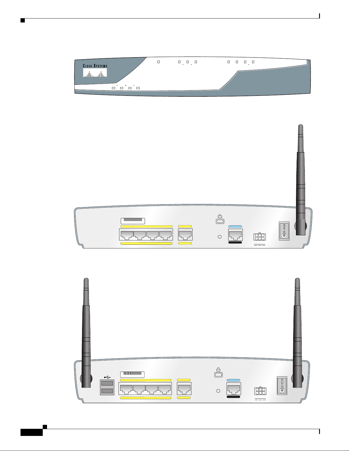
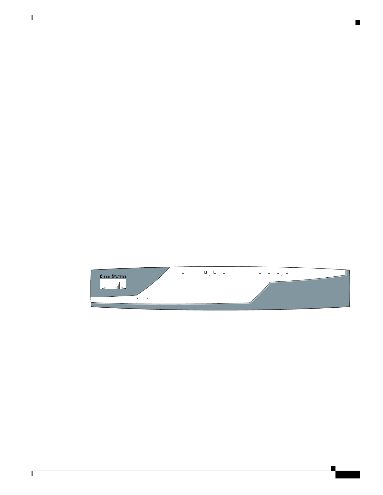
The front panels of the Cisco 851 and Cisco 871 routers are identical. (See Figure 1-1.) Figure 1-2 shows
the back panel of the Cisco 851 router, and Figure 1-3 shows the back panel of the Cisco 871 router.
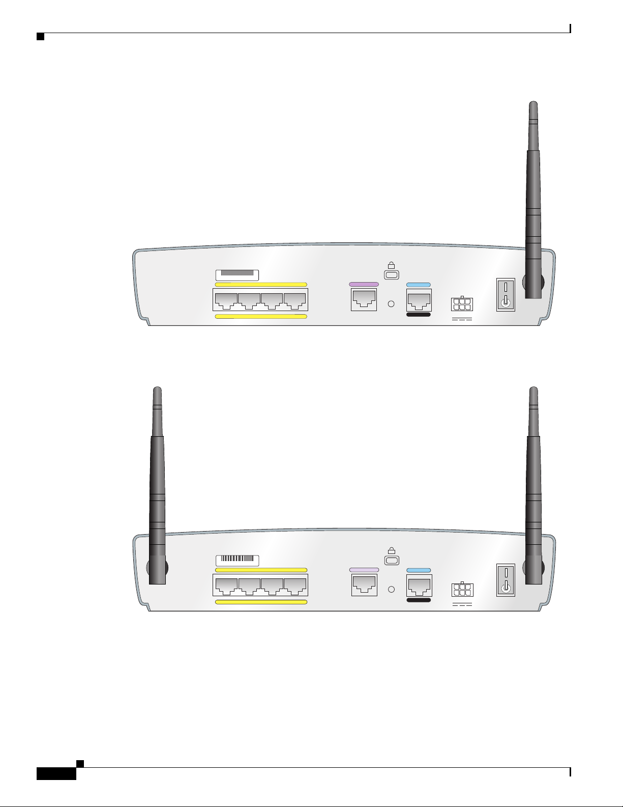
The Cisco 851 wireless model supports the use of a single 2.4-GHz antenna (see Figure 1-2), and the
Cisco 871 wireless model supports the use of two 2.4-GHz antennas (see Figure 1-3).
Cisco 850 Series and Cisco 870 Series Access Routers Hardware Installation Guide
OL-5331-01
1-1
Page 16
General Descriptions of the Router Models
OK LNK PPP VPN OK DATA
WLAN
RXD
WAN
TXD
CISCO 800 SERIES
ETHERNET LAN
0123
122347
122245
SN: XXXNNNNXXXX
LAN
4
3
2
1
Cisco 851W
CONSOLE
AUX
RESET
+5,+12 VDC
WAN
FE4
FE0
FE1
FE2
FE3
LAN
FE0
FE1
FE2
FE3
Cisco 871W
CONSOLE
AUX
RESET
+5,+12 VDC
LEFT
RIGHT / PRIMARY
1
0
WAN
FE4
122241
SN: XXXNNNNXXXX
Figure 1-1 Cisco 851 and Cisco 871 Router Front Panel
Figure 1-2 Cisco 851 Router Back Panel
Chapter 1 Product Overview
1-2
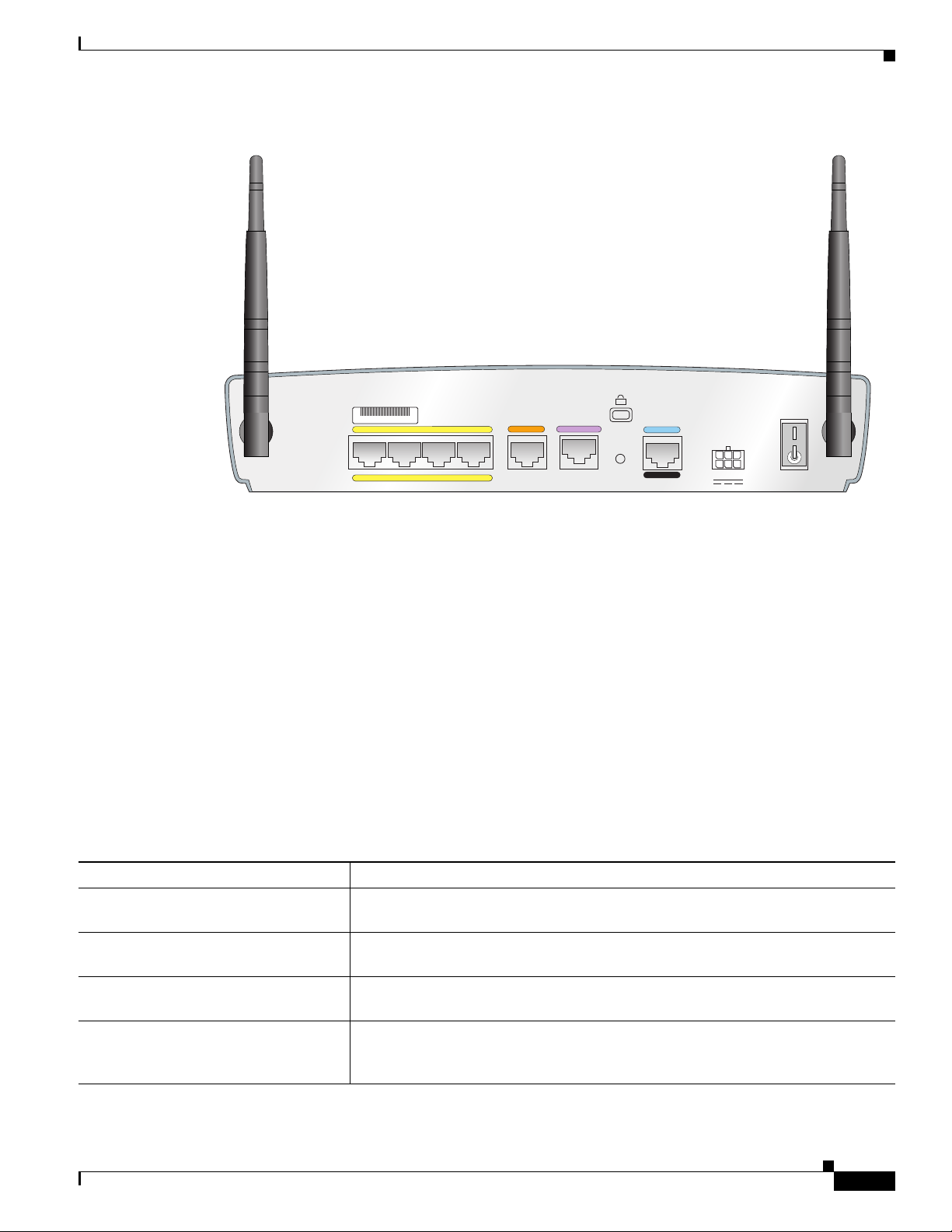
Figure 1-3 Cisco 871 Router Back Panel with Antennas
Cisco 850 Series and Cisco 870 Series Access Routers Hardware Installation Guide
OL-5331-01
Page 17
Chapter 1 Product Overview
OK CD PPP VPN OK DATA
WLAN
RXD
ADSL
TXD
CISCO 800 SERIES
ETHERNET LAN
0123
122348
Router Ports on the Cisco 851 and Cisco 871 Back Panel
The Cisco 851 and Cisco 871 routers have the following ports on the back panel:
• Four 10/100BASE-T RJ-45 Fast Ethernet LAN ports with a built-in switch
• One 10/100BASE-T RJ-45 WAN Fast Ethernet port
• One RJ-45 console port
• Two USB ports (on the Cisco 871 router only)
USB Port Power Allocation on the Cisco 871 Router
The power available for each of the two USB ports is 500 mA. Power is dynamically allocated to each
port as needed, up to 500 mA.
Cisco 857 and Cisco 877 ADSL-over-POTS Routers
The Cisco 857 and Cisco 877 routers are asymmetric digital subscriber line (ADSL)-over-plain old
telephone service (POTS) routing devices. The routers have an integrated 4-port Ethernet switch for the
LAN and an ADSL physical interface for the WAN, allowing the routers to connect a corporate
telecommuter or small office to corporate LANs and the Internet.
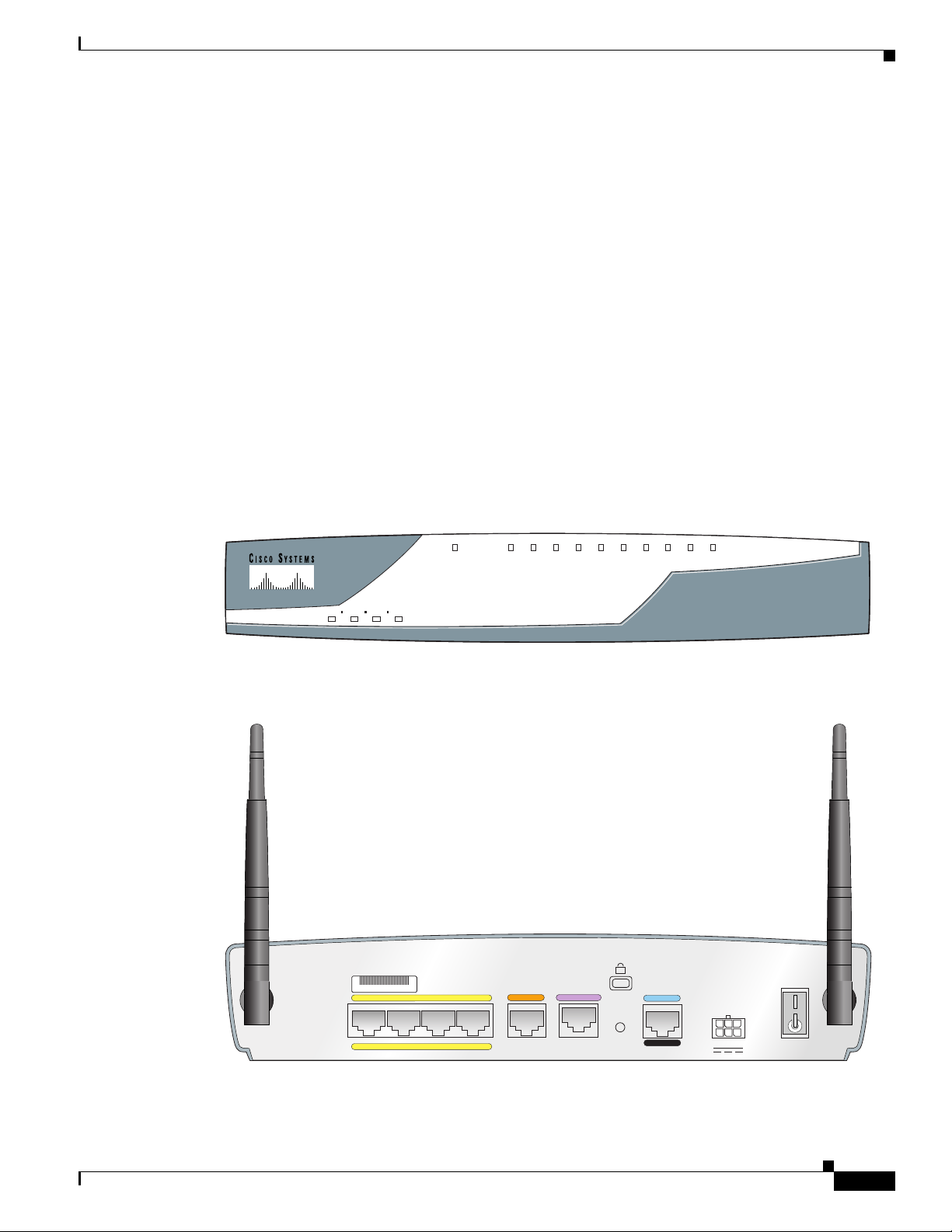
The front panels of the Cisco 857 and Cisco 877 routers are identical. (See Figure 1-4.) The back panels
of these two routers are similar except for their model numbers, which differ. Figure 1-5 shows the back
panel of a Cisco 857 router, and Figure 1-6 shows the back panel of a Cisco 877 router.
General Descriptions of the Router Models
Figure 1-4 Cisco 857 and Cisco 877 Router Front Panel
OL-5331-01
Cisco 850 Series and Cisco 870 Series Access Routers Hardware Installation Guide
1-3
Page 18
General Descriptions of the Router Models
ADSLoPOTS
LAN
FE0
FE1
FE2
FE3
Cisco 857W
CONSOLE
AUX
RESET
+5,+12 VDC
122242
SN: XXXNNNNXXXX
ADSLoPOTS
LAN
FE0
FE1
FE2
FE3
Cisco 877W
CONSOLE
AUX
RESET
+5,+12 VDC
127093
SN: XXXNNNNXXXX
LEFT
RIGHT/PRIMARY
Figure 1-5 Cisco 857 Router Back Panel, with Antenna Installed
Chapter 1 Product Overview
Figure 1-6 Cisco 877 Router Back Panel, with Antennas Installed
1-4
Cisco 850 Series and Cisco 870 Series Access Routers Hardware Installation Guide
OL-5331-01
Page 19
Chapter 1 Product Overview
OK CD PPP VPN OK DATA
WLAN
RXD
ADSL
B1
ISDN
TXD
CISCO 800 SERIES
ETHERNET LAN
0123
122349
LNK
–––––
B2
LEFT
RIGHT / PRIMARY
AUX
ADSL o ISDN
LAN
FE0
FE1
FE2
FE3
Cisco 876W
CONSOLE
RESET
+5,+12 VDC
ISDN S/T
SN: XXXNNNNXXXX
Router Ports on the Cisco 857 and Cisco 877 Back Panel
The Cisco 857 and Cisco 877 routers have the following ports on the back panel:
• Four 10/100BASE-T RJ-45 Fast Ethernet LAN ports with a built-in switch
• One ADSL-over-POTS port
• One RJ-45 console port
Cisco 876 ADSL-over-ISDN Router
The Cisco 876 router is an asymmetric digital subscriber line (ADSL)—over—ISDN routing device. The
router has an integrated 4-port Ethernet switch for the LAN and an ADSL physical interface for the
WAN, and ISDN BRI WAN connectivity. This ISDN BRI interface can be used for normal WAN
connections or can be configured as a backup connection for the ADSL WAN interface. These features
allow the routers to connect a corporate telecommuter or a small office to a central office or an Internet
service provider (ISP) over an ADSL interface.
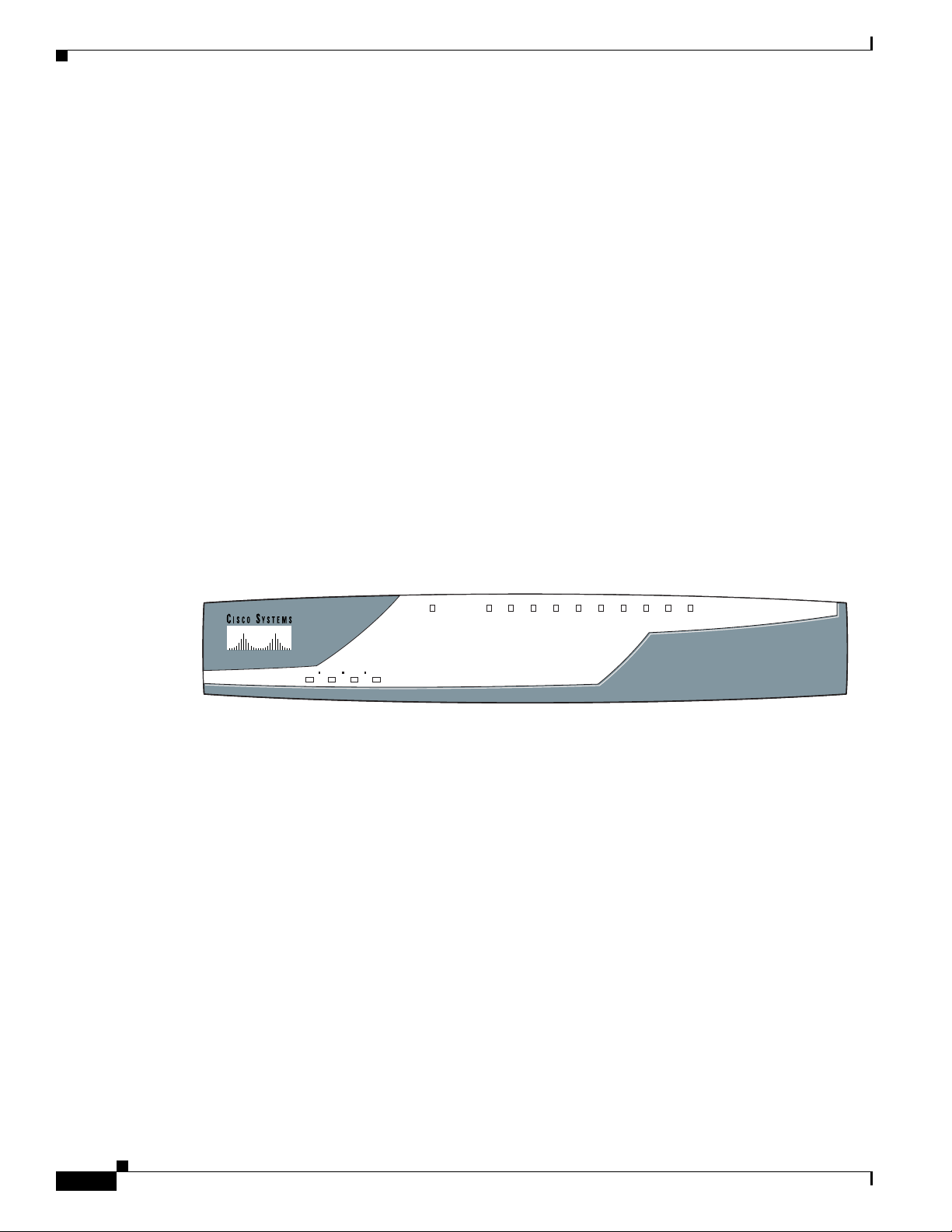
Figure 1-7 shows the front panel of the Cisco 876 router, and Figure 1-8 shows the back panel.
General Descriptions of the Router Models
Figure 1-7 Cisco 876 Router Front Panel
Figure 1-8 Cisco 876 Router Back Panel, with Antennas Installed
OL-5331-01
Cisco 850 Series and Cisco 870 Series Access Routers Hardware Installation Guide
1-5
Page 20
General Descriptions of the Router Models
122350
OK CD PPP VPN OK DATA
WLAN
RXD
G.SHDSL
B1
ISDN
TXD
CISCO 800 SERIES
ETHERNET LAN
0123
LNK
–––––
B2
Router Ports on the Cisco 876 Back Panel
The Cisco 876 router has the following ports on the back panel:
• Four 10/100BASE-T RJ-45 Fast Ethernet LAN ports with a built-in switch
• One 10/100BASE-T RJ-45 WAN Fast Ethernet port
• One ISDN S/T port
• One ADSL-over-ISDN port
• One RJ-45 console port
Cisco 878 SHDSL Router
The Cisco 878 router can connect a corporate telecommuter or small office to an Internet service
provider (ISP) over multirate symmetrical high-data-rate digital subscriber lines (G.SHDSLs) to a
corporate LAN and to the Internet.
The router has an integrated 4-port Ethernet switch for the LAN, a G.SHDSL physical interface for the
WAN, and an ISDN BRI interface. The ISDN BRI S/T port can be used for remote management. The
router is capable of bridging and multiprotocol routing between LAN and WAN ports.
Chapter 1 Product Overview
Figure 1-9 shows the front panel of the Cisco 878 router, and Figure 1-10 shows the back panel.
Figure 1-9 Cisco 878 Router Front Panel
1-6
Cisco 850 Series and Cisco 870 Series Access Routers Hardware Installation Guide
OL-5331-01
Page 21
Chapter 1 Product Overview
122244
LEFT
RIGHT / PRIMARY
G.SHDSL
LAN
4
3
2
1
Cisco 878W
CONSOLE
AUX
RESET
+5,+12 VDC
ISDN S/T
FE0
FE1
FE2
FE3
SN: XXXNNNNXXXX
Figure 1-10 Cisco 878 Router Back Panel with Antennas
Feature Summary
Router Ports on the Cisco 878 Back Panel
The Cisco 878 router has the following ports on the back panel:
• Four 10/100BASE-T RJ-45 Fast Ethernet LAN ports with a built-in switch
• One ISDN S/T port
• One G.SHDSL port
• One RJ-45 console port
Feature Summary
Table 1-1 summarizes the features of these routers.
Ta b l e 1-1 Hardware Feature Summary
Feature Description
10BASE-T/100BASE-T built-in switch
ports
Fast Ethernet WAN port Cisco 851 and Cisco 871 routers only. Provides connection to 10/100BASE-T. Can
ADSL-over-POTS port Cisco 857 and Cisco 877 routers only. Provides connection to an ADSL network.
ISDN S/T port Cisco 876 and Cisco 878 routers only. Provides remote management functions
Provides connection to 10/100BASE-T (10/100-Mbps) Ethernet networks.
Compatible with 10/100-Mbps devices.
be connected to other network devices, such as cable modem, ADSL, and router.
Does not support the autoswitch function.
when the main ADSL or SHDSL link goes down by connecting to the ISDN service
provider. Can be used for dial backup on Cisco 876 routers only.
OL-5331-01
Cisco 850 Series and Cisco 870 Series Access Routers Hardware Installation Guide
1-7
Page 22

Chapter 1 Product Overview
Feature Summary
Table 1-1 Hardware Feature Summary (continued)
Feature Description
ADSL-over-ISDN port Cisco 876 router only. Provides connection to an ADSL-over-ISDN network. Does
not support the autoswitch function.
G.SHDSL port Cisco 878 router only. Provides 2-wire or 4-wire connection to a G.SHDSL
network.
Console port Provides a connection to the terminal or PC for software configuration or
troubleshooting using the command-line interface (CLI). The console port may be
configured as a virtual auxiliary port (using the CLI) for dial backup and remote
management.
Flash memory Cisco 850 series routers:
20 MB of flash memory (default and maximum)
Cisco 870 series routers:
20 MB of flash memory (default)
28 MB of flash memory for routers ordered with a Cisco IOS Advanced IP Services
image or Enterprise Services image.
Expandable by 8, 16, or 32 MB, up to a maximum of 52 MB.
Synchronous dynamic RAM (SDRAM) Cisco 850 series routers: 64 MB of SDRAM on board.
Cisco 870 series routers: 128 MB of SDRAM on board.
Expandable by 64 or 128 MB, up to a maximum of 256 MB.
Router Reset button Resets the router configuration to the factory default.
Dying gasp Detects whether the router is about to lose power, and sends a signal to warn the
digital subscriber line access multiplexer (DSLAM) about the impending line drop.
Wall-mount feature Brackets for mounting the router on a wall or vertical surface.
USB ports Cisco 871 router only. Supports USB-compatible devices such as security tokens
and flash memory sticks.
IPSec hardware accelerator The security processor implements symmetric key encryption, public key
encryption, authentication, and data compression in hardware.
Integrated 802.11b/g radio module (Optional) Provides connectivity to a wireless LAN using IEEE 802.11b/g
standards. Enables the router to act as an access point (AP) in infrastructure mode.
External power-over-Ethernet (PoE)
module
(Optional) Provides inline power for powered devices (such as PCs and phones)
that are connected to the router.
Kensington security slot Allows the router to be secured to a desktop or other surface by using Kensington
lockdown equipment.
Security features Provides support for virtual private networks (VPNs), Cisco IOS Firewall, and
IPSec. For information about software security features, see the Cisco
and Cisco
870 Series Access Routers Software Configuration Guide.
Autosensing function Eliminates the need for a crossover cable and allows the router to detect
medium-dependent interface in normal mode (MDI) or medium-dependent
interface in crossover mode (MDIX) in any other PC or hub with a straight-through
cable or a crossover cable. The router is capable of bridging and multiprotocol
routing between the LAN and WAN ports.
850 Series
1-8
Cisco 850 Series and Cisco 870 Series Access Routers Hardware Installation Guide
OL-5331-01
Page 23
Chapter 1 Product Overview
120729, 78-16262-01 Rev A0
G
.S
H
D
S
L
ISDN S/T
LAN
FE0
FE1
FE2
FE3
Cisco 878
CONSOLE
AUX
R
E
SE
T
+5,+9 V
D
C
S
N
: A
A
A
N
N
N
N
X
X
X
X
SN: AAANNNNXXXX
Hardware Features
This section provides an overview of the hardware features of Cisco 850 series and Cisco 870 series
routers and includes the following topics:
• Serial Number Location
• LED Indicators on the Routers
• Integrated 802.11b/g Radio Module (Wireless Models Only)
• Supported Cisco Radio Antennas (Wireless Models Only)
• External Power-over-Ethernet Module (Optional)
• Router Memory
• Router Hardware Security
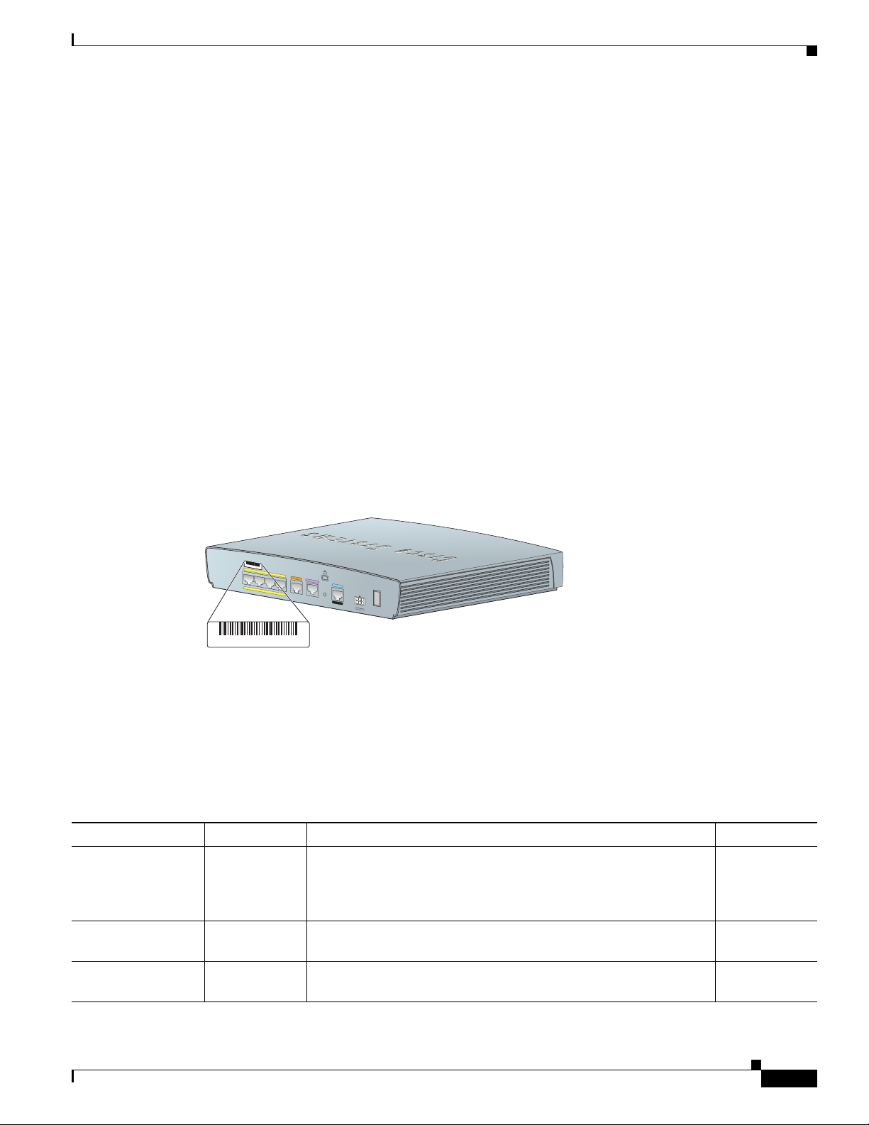
Serial Number Location
The serial number label for the router is located on the rear of the chassis, at the left edge (see
Figure 1-11).
Hardware Features
Figure 1-11 Serial Number Location
LED Indicators on the Routers
The router LEDs that indicate status or activity on the router are located on the front panel of the routers.
Table 1-2 lists and describes the LEDs.
Ta b l e 1-2 LED Indicators on the Routers
LED Color Description Router Model
OK Green On when DC power is being supplied to the router. The light blinks
if an error occurs during bootup.
WA N LN K Green On if the WAN Ethernet carrier detects status and connects to the
digital subscriber line access multiplexer (DSLAM).
WA N RX D Green Blinks when WAN DSL or WAN Internet receives data. Cisco 851,
All Cisco 850
series and
Cisco 870
series
Cisco 851,
Cisco 871
Cisco 871
OL-5331-01
Cisco 850 Series and Cisco 870 Series Access Routers Hardware Installation Guide
1-9
Page 24

Chapter 1 Product Overview
Hardware Features
Table 1-2 LED Indicators on the Routers (continued)
LED Color Description Router Model
WA N TX D Green Blinks when WAN DSL or WAN Internet transmits data. Off when
no data is being uploaded.
ADSL CD Green On if the ADSL carrier detects status and connects to the DSLAM. Cisco 857,
ADSL RXD Green Blinks when the ADSL interface receives data. Off when there is no
data.
ADSL TXD Green Blinks when the ADSL interface transmits data. Off when no data
is being uploaded.
G.SHDSL CD Green On if the SHDSL carrier detects status and connects to the DSLAM. Cisco 878
G.SHDSL RXD Green Blinks when the SHDSL interface receives data. Off when there is
no data.
G.SHDSL TXD Green Blinks when the SHDSL interface transmits data. Off when no data
is being uploaded.
ISDN LNK Green On when the ISDN D channel connects. Cisco 876,
ISDN B1 Green On when the ISDN B1 channel connects. Blinks when the B1
channel receives or sends data, or when data passes through ISDN
channel 1.
ISDN B2 Green On when the ISDN B2 channel connects. Blinks when the B2
channel receives or sends data, or when data passes through ISDN
channel 2.
PPP Green PPP-over-Ethernet (PPPoE) or PPP-over-ATM (PPPoA) client
status. On if at least one PPPoE or PPPoA client session is running.
Off if neither PPPoE nor PPPoA is running.
VPN Green VPN tunnel status. On when at least one crypto (IPSec) session is
running. Off when no crypto session is running.
WLAN OK Green Shows whether the wireless link status is operational. Blinks if no
client is associated. Solid green if at least one client is associated.
WLAN DATA Green Wireless LAN link traffic. Blinks if there is traffic on the wireless
LAN. Off if there is no traffic.
Cisco 851,
Cisco 871
Cisco 876,
Cisco 877
Cisco 857,
Cisco 876,
Cisco 877
Cisco 857,
Cisco 876,
Cisco 877
Cisco 878
Cisco 878
Cisco 878
Cisco 876,
Cisco 878
Cisco 876,
Cisco 878
All Cisco 850
series and
Cisco 870
series
All Cisco 850
series and
Cisco 870
series
All Cisco 850
series and
Cisco 870
series wireless
models
All Cisco 850
series and
Cisco 870
series wireless
models
1-10
Cisco 850 Series and Cisco 870 Series Access Routers Hardware Installation Guide
OL-5331-01
Page 25

Chapter 1 Product Overview
Hardware Features
Table 1-2 LED Indicators on the Routers (continued)
LED Color Description Router Model
ETHERNET LAN 0 Green On when a device connects to the Ethernet LAN 0 port. Blinks when
the Ethernet LAN 0 port receives or sends data, or when data passes
through the port.
ETHERNET LAN 1 Green On when a device connects to the Ethernet LAN 1 port. Blinks when
the Ethernet LAN 1 port receives or sends data, or when data passes
through the port.
ETHERNET LAN 2 Green On when a device connects to the Ethernet LAN 2 port. Blinks when
the Ethernet LAN 2 port receives or sends data, or when data passes
through the port.
ETHERNET LAN 3 Green On when a device connects to the Ethernet LAN 3 port. Blinks when
the Ethernet LAN 3 port receives or sends data, or when data passes
through the port.
All Cisco 850
series and
Cisco 870
series
All Cisco 850
series and
Cisco 870
series
All Cisco 850
series and
Cisco 870
series
All Cisco 850
series and
Cisco 870
series
Integrated 802.11b/g Radio Module (Wireless Models Only)
The Cisco 850 series and Cisco 870 series wireless routers have an integrated IEEE 802.11b/g radio
module that operates as a wireless access point in infrastructure mode. The wireless routers have two
reverse-polarity threaded Neill-Concelman (RP-TNC) connectors on the back panel. The dipole swivel
antennas that were shipped with the router connect to the RP-TNC connectors to operate the 802.11b/g radio
module.
The wireless operations can be configured by using the Cisco Router and Security Device Manager
(SDM) web-based application, or by using the Cisco IOS command-line interface (CLI). See the
Cisco
Router and Security Device Manager (SDM) Quick Start Guide or the Cisco Access Router
Wireless Configuration Guide for more information.
OL-5331-01
Cisco 850 Series and Cisco 870 Series Access Routers Hardware Installation Guide
1-11
Page 26

Chapter 1 Product Overview
Hardware Features
Supported Cisco Radio Antennas (Wireless Models Only)
Table 1-3 lists the Cisco antennas that are supported on the Cisco 850 series and Cisco 870 series
wireless routers.
Ta b l e 1-3 Cisco Antennas Supported on the Cisco 850 Series and Cisco 870 Series Wireless Routers
Cisco Part Number Antenna Type Maximum Gain Description
23.7786.51 Omnidirectional 2.2 dBi This is the default antenna. Swivel-mount dipole
antenna operating in the 2.4- to 2.5-GHz band. This
antenna is designed for use with Cisco wireless
products utilizing an RP-TNC connector. For more
information, see the
Dipole Antenna (23.7786.51) document.
AIR-ANT4941 Omnidirectional 2.2 dBi Swivel-mount dipole antenna operating in the 2.4-
to 2.5-GHz band. This antenna is designed for use
with Cisco wireless products utilizing an RP-TNC
connector. For more information, see the
Cisco Aironet 2.4 Ghz Articulated Dipole Antenna
(AIR-ANT4941) document.
AIR-ANT1728 Omnidirectional 5.2 dBi Ceiling-mount antenna operating in the 2.4- to
2.5-GHz band. This antenna has a clip that allows
it to be mounted to a drop-ceiling cross member.
For more information, see the
Gain Omnidirectional Ceiling Mount Antenna
(AIR-ANT1728) document.
Note This antenna is not supported in Japan.
AIR-ANT3549 Patch 9 dBi Wall-mount antenna operating in the 2.4- to
2.5-GHz band.
Note This antenna is not supported in the
United
AIR-ANT5959 Diversity
omnidirectional
2.35 dBi Ceiling-mount antenna operating in the 2.4- to
2.5-GHz band. This antenna has a clip that allows
it to be mounted to a drop-ceiling cross member.
For more information, see the
Diversity Omnidirectional Ceiling Mount Antenna
(AIR-ANT5959) document.
Cisco 2.4-GHz Swivel-Mount
Cisco Aironet High
States and Canada.
Cisco Aironet 2 dBi
External Power-over-Ethernet Module (Optional)
The optional external power-over-Ethernet (PoE) module is a standalone device that connects to the
Ethernet ports on the router on one side (To ROUTER) and to powered devices (such as PCs, laptops,
and IP phones) on the other side (To LAN). The PoE module has an independent power source that can
provide inline power to devices connected to each of the four Ethernet ports, so that these devices do not
need separate power sources.
Cisco 850 Series and Cisco 870 Series Access Routers Hardware Installation Guide
1-12
OL-5331-01
Page 27
Chapter 1 Product Overview
121040
48VDC
TO ROUTER
3210
1
2
121039
2
TO LAN
3210
PWR
1
Caution To ensure proper PoE module operation, do not connect the PoE module power supply to the PoE module
before you connect the PoE module to the router. Do not connect ISDN devices to the Ethernet ports on
the PoE module; doing so may damage the hardware.
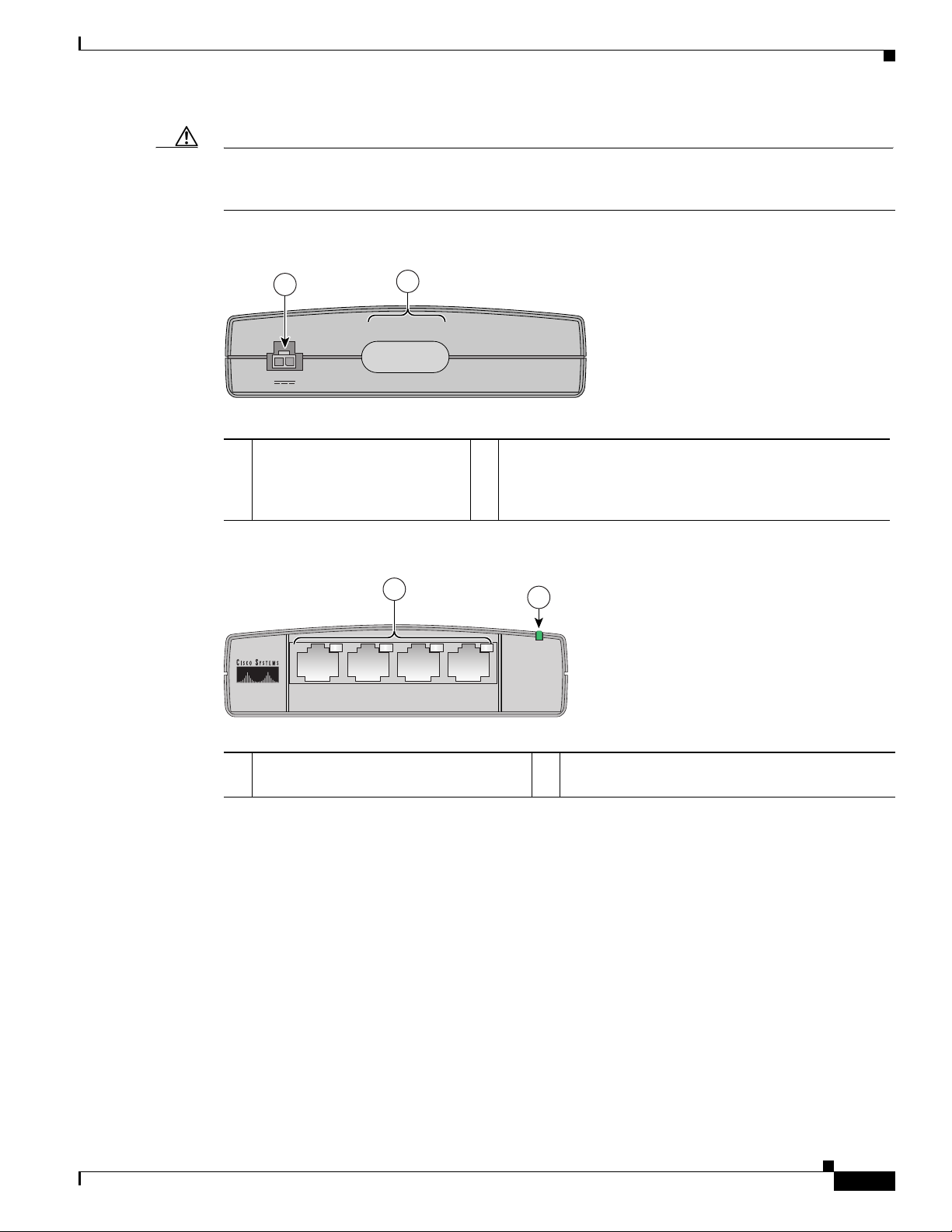
Figure 1-12 Power-over-Ethernet Module Front Panel
1 Power adapter input jack 2 Cable numbers associated with the corresponding Ethernet
Hardware Features
ports on the back panel. The integrated cable below the
cable number label, consisting of four RJ-45 connectors
organized by a plastic clip, is not shown in this illustration.
Figure 1-13 Power-over-Ethernet Module Back Panel
1 LED indicators and Ethernet ports for
2 Power indicator
connecting powered devices
OL-5331-01
Cisco 850 Series and Cisco 870 Series Access Routers Hardware Installation Guide
1-13
Page 28

Hardware Features
122351
+5
,+
12 V
D
C
LE
F
T
R
IG
H
T / P
R
IM
A
R
Y
LA
N
F
E
0F
E
1F
E
2
F
E
3
Cisco 871W
C
O
N
S
O
LE
A
U
X
R
E
S
E
T
1
0
W
A
N
F
E
4
1
2
4
6
To LAN
3210
PWR
3
5
7
SN: XXXNNNNXXXX
Figure 1-14 Installing the PoE Module
Chapter 1 Product Overview
1 Cisco 870 series router 5 Router power adapter
2 Ethernet cables on the PoE module (four
6 PoE power plug
RJ-45 connectors in series)
3 PoE module 7 Router power plug
4 PoE power adapter
1-14
Cisco 850 Series and Cisco 870 Series Access Routers Hardware Installation Guide
OL-5331-01
Page 29

Chapter 1 Product Overview
142607
+5,+12 VDC
LEFT
R
IG
HT / PR
IM
A
RY
LAN
FE0
FE1
FE2
F
E3
Cisco 871W
CO
N
SO
LE
AU
X
RESET
1
0
W
AN
FE4
1
3
SN: XXXNNNNXXXX
To LAN
3210
PWR
2
4
Figure 1-15 Connecting the PoE Module to the Router
Hardware Features
1 Cisco 870 series router 3 Four RJ-45 Ethernet plugs, in series, from the
PoE module (plug these into the Ethernet
ports on the router)
2 RJ-45 Ethernet ports on the router 4 PoE module
Cisco 850 Series and Cisco 870 Series Access Routers Hardware Installation Guide
OL-5331-01
1-15
Page 30

Hardware Features
142608
+5,+12 VDC
LEFT
R
IG
H
T
/ P
R
IM
A
R
Y
L
A
N
F
E
0
F
E
1
F
E
2
FE
3
Cisco 871W
C
O
N
S
O
LE
A
U
X
RESET
1
0
W
A
N
F
E
4
SN: XXXNNNNXXXX
Figure 1-16 PoE Module Connected to the Router
Chapter 1 Product Overview
LED Indicators on the PoE Module
Ta b l e 1-4 LED Indicators for the PoE Module
LED Color and Behavior Description
POE ports 0, 1, 2, 3 None No powered device detected
Solid amber Power administratively down
Solid green Power provided to the device
Blinking amber Fault detected in power delivery
Blinking green Power denied to the device
Router Memory
Cisco 850 series and Cisco 870 series routers support the following types of memory:
• Flash Memory
• SDRAM
Flash Memory
Flash memory stores the image of the ROMMON boot code, the Cisco IOS software, and the router
configuration file. The router provides two onboard StrataFlash devices, one with 16 MB and the other
with 4 MB of memory, for a total of 20 MB of onboard flash memory.
Cisco 850 Series and Cisco 870 Series Access Routers Hardware Installation Guide
1-16
OL-5331-01
Page 31

Chapter 1 Product Overview
• For Cisco 850 series routers, the default and maximum flash memory is 20 MB. This is not
upgradable.
• For Cisco 870 series routers, an expansion slot allows for an additional 8 MB, 16 MB, or 32 MB of
memory. The maximum flash memory is 52 MB. The default flash memory depends on which
Cisco
IOS image is ordered with the router.
–
By default, the router ships with 4 MB in the expansion slot, for a total of 24 MB of flash
memory.
–
If ordered with a Cisco IOS Advanced IP Services image or Enterprise Services image, the
router ships by default with 8 MB of memory in the expansion slot, for a total of 28 MB of
flash
memory.
SDRAM
SDRAM stores the Cisco IOS software and provides memory for data created during packet processing.
The router provides 128 MB of onboard SDRAM, with an expansion slot that allows an additional
64
MB or 128 MB, up to a maximum of 256 MB of SDRAM.
Router Hardware Security
Regulatory Compliance
The Cisco 850 series and Cisco 870 series routers have a Kensington security slot on the back panel. To
secure the router to a desktop or other surface, use the Kensington lockdown equipment.
Regulatory Compliance
For compliance and safety information, see the Regulatory Compliance and Safety Information for
Cisco
800 Series and SOHO Series Routers document that was shipped with the router.
For wireless models, also see the Declarations of Conformity and Regulatory Information for Cisco
Access Products with 802.11a/b/g and 802.11b/g Radios document that was shipped with the router.
OL-5331-01
Cisco 850 Series and Cisco 870 Series Access Routers Hardware Installation Guide
1-17
Page 32

Regulatory Compliance
Chapter 1 Product Overview
1-18
Cisco 850 Series and Cisco 870 Series Access Routers Hardware Installation Guide
OL-5331-01
Page 33

Preinstallation Information
This chapter provides information about safety, unpacking the router, and preparing for installation for
Cisco
851, Cisco 857, Cisco 871, Cisco 876, Cisco 877, and Cisco 878 routers. It contains the following
sections:
• Safety Warnings and Guidelines, page 2-1
• Preventing Damage to the Router, page 2-4
• Unpacking the Box, page 2-4
• Preparing for Installation, page 2-5
• What to Do Next, page 2-6
Safety Warnings and Guidelines
CHA P TER
2
Warning
Warning
Warning
Warning
This section provides the safety warnings and guidelines for working with wireless and nonwireless
routers that are applicable to the Cisco
Before installing the router and the optional Power-over-Ethernet (PoE) module, read the following
warnings:
Read the installation instructions before connecting the system to the power source.
Voltages that present a shock hazard may exist on Power over Ethernet (PoE) circuits if
interconnections are made using uninsulated exposed metal contacts, conductors, or terminals.
Avoid using such interconnection methods, unless the exposed metal parts are located within a
restricted access location and users and service people who are authorized within the restricted
access location are made aware of the hazard. A restricted access area can be accessed only through
the use of a special tool, lock and key or other means of security.
No user-serviceable parts inside. Do not open.
Installation of the equipment must comply with local and national electrical codes.
850 series and Cisco 870 series routers.
Statement 1004
Statement 1072
Statement 1073
Statement 1074
OL-5331-01
Cisco 850 Series and Cisco 870 Series Access Routers Hardware Installation Guide
2-1
Page 34

Safety Warnings and Guidelines
Chapter 2 Preinstallation Information
Warning
Warning
Warning
Warning
Warning
Warning
This product relies on the building’s installation for short-circuit (overcurrent) protection. Ensure that
the protective device is rated not greater than: 120 VAC, 15A U.S. (240 VAC, 10A international)
Statement 1005
To avoid electric shock, do not connect safety extra-low voltage (SELV) circuits to telephone-network
voltage (TNV) circuits. LAN ports contain SELV circuits, and WAN ports contain TNV circuits. Some
LAN and WAN ports both use RJ-45 connectors. Use caution when connecting cables.
Statement 1021
Do not work on the system or connect or disconnect cables during periods of lightning activity.
Statement 1001
Ultimate disposal of this product should be handled according to all national laws and regulations.
Statement 1040
To reduce the risk of fire, use only No. 26 AWG or larger telecommunication line cord.
Statement 1023
Before working on a chassis or working near power supplies, unplug the power cord on AC units;
disconnect the power at the circuit breaker on DC units.
Statement 12
Warning
Warning
During this procedure, wear grounding wrist straps to avoid ESD damage to the card. Do not directly
touch the backplane with your hand or any metal tool, or you could shock yourself.
Statement 94
Before working on equipment that is connected to power lines, remove jewelry (including rings,
necklaces, and watches). Metal objects will heat up when connected to power and ground and can
Warning
cause serious burns or weld the metal object to the terminals.
This equipment is not designed for making emergency telephony calls when the power fails.
Statement 43
Alternative arrangements should be made for access to emergency services. Access to emergency
services can be affected by any call-barring function of this equipment.
Caution Inline power circuits provide current through the communication cable. Use the cable provided by Cisco
Statement 199
or a communication cable with a minimum of 24 AWG.
2-2
Cisco 850 Series and Cisco 870 Series Access Routers Hardware Installation Guide
OL-5331-01
Page 35

Chapter 2 Preinstallation Information
Additional Warnings for Wireless Routers
Safety Warnings and Guidelines
Warning
Warning
In order to comply with FCC radio frequency (RF) exposure limits, antennas should be located at a
minimum of 7.9 inches (20 cm) or more from the body of all persons.
Do not operate your wireless network device near unshielded blasting
environment unless the device has been modified to be especially qualified for such use.
Statement 245B
General Safety Guidelines for Wireless Routers
The following are guidelines for the wireless router models:
• Do not touch or move antenna(s) while the unit is transmitting or receiving.
• Do not hold any component containing a radio so that the antenna is very close to or touching any
exposed parts of the body, especially the face or eyes, while transmitting.
• The use of wireless devices in hazardous locations is limited to the constraints posed by the local
codes, the national codes, and the safety directors of such environments.
Preventing Electrostatic Discharge Damage
Electrostatic discharge (ESD) is a transfer of electrostatic charge between bodies of different
electrostatic potentials, such as an operator and a piece of electrical equipment. It occurs when electronic
components are improperly handled, and it can damage equipment and impair electrical circuitry.
Electrostatic discharge is more likely to occur in the presence of synthetic fibers and dry atmosphere.
Always use the following ESD-prevention procedures when removing and replacing components:
Statement 332
caps or in an explosive
OL-5331-01
Step 1 Wear an ESD-preventive wrist strap that you provide, ensuring that it makes good skin contact.
Caution To properly guard against ESD damage and shocks, the wrist strap and cord must operate effectively.
Always follow the warnings and guidelines in this section.
Step 2 Do not touch any exposed contact pins or connector shells of interface ports that do not have a cable
attached.
If cables are connected at one end only, do not touch the exposed pins at the unconnected end of the
cable. This device is intended for use in residential and commercial environments only.
Caution Periodically check the resistance value of the antistatic strap, which should be between 1 and
10 megohms (Mohm).
Cisco 850 Series and Cisco 870 Series Access Routers Hardware Installation Guide
2-3
Page 36

Preventing Damage to the Router
Preventing Damage to the Router
Follow these guidelines when connecting devices to your router:
• Connect the color-coded cables supplied by Cisco Systems to the color-coded ports on the back
panel.
• If you must supply your own cable, see Appendix A, “Specifications,” for cabling specifications. If
this appendix does not provide specifications for a particular cable, we strongly recommend
ordering the cable from Cisco
Systems.
Unpacking the Box
Table 2-1 lists the quantity of items that are shipped with each router model in the Cisco 850 series and
the Cisco 870 series routers. Figure 2-1 depicts the items.
Verify that you have received all the items. If any is missing or damaged, contact your customer service
representative.
Chapter 2 Preinstallation Information
Ta b l e 2-1 Items Shipped with Cisco 850 Series and Cisco 870 Series Routers
Item
Cisco 851 and
Cisco
871 Routers
Cisco 857 and
Cisco
877 Routers Cisco 876 Router Cisco 878 Router
Ethernet cable(s) 2 1 1 1
DSL1 cable
ISDN4 S/T cable
Not applicable 1
2
Not applicable Not applicable Optional Optional
3
1
3
1
Console cable 1 1 1 1
Console-auxiliary5 cable
Optional Optional Optional Optional
Power adapter 1 1 1 1
Power cord
Cisco documentation
Cisco Router and Security Device
6
7
1 1 1 1
1 1 1 1
1 1 1 1
Manager (SDM) software CD
Swivel-mount dipole antenna
(wireless router models only)
1. DSL = digital subscriber line. Used for an asynchronous digital subscriber line (ADSL) or multirate symmetrical high-data-rate digital subscriber line
(G.SHDSL).
2. An RJ-11-to-RJ-11 straight-through cable is shipped, unless an RJ-11-to-RJ-11 crossover cable is specified.
3. An RJ-11-to-RJ-11 straight-through cable is shipped, unless an RJ-11-to-RJ-11 crossover cable or an RJ-11-to-RJ-45 cable is specified.
4. ISDN = Integrated Services Digital Network.
5. Console-auxiliary cable is used to connect the router console port to an async modem for dial backup or remote management.
6. Power cords are ordered as applicable to country or geographic region.
7. Includes the Regulatory Compliance and Safety Information for Cisco 800 Series and SOHO Series Routers document and the Cisco 850 Series and
Cisco 870 Series Access Routers Cabling and Setup Quick Start Guide. Also includes the Declarations of Conformity and Regulatory Information for
Cisco Access Products with 802.11a/b/g and 802.11b/g Radios document for wireless models.
Cisco 851:
1
antenna
Cisco 871:
2
antennas
Cisco 857:
1
antenna
Cisco 877:
2
antennas
2 2
2-4
Cisco 850 Series and Cisco 870 Series Access Routers Hardware Installation Guide
OL-5331-01
Page 37

Chapter 2 Preinstallation Information
Figure 2-1 Items Included with the Cisco 850 Series and Cisco 870 Series Routers
Preparing for Installation
1 Yellow Ethernet cable 5 Black power cord for adapter
2 Lavender DSL cable (optional) 6 Product documentation
3 Light blue console cable 7 Cisco SDM software CD
4 Router power adapter 8 Swivel-mount dipole antenna (wireless router
Preparing for Installation
Before installing the router and connecting devices to the router, perform these tasks:
Step 1 Obtain a broadband or Ethernet connection from your service provider.
Step 2 Remove the cables and product documentation from the plastic bag. Remove the router power adapter
and the black power cord from the accessory kit.
Step 3 If you ordered a wireless router, remove the antennas from the box.
Step 4 If you ordered a power-over-Ethernet (PoE) module, remove the PoE, its power adapter, and its power
cord from the box.
Step 5 Gather the Ethernet devices to be connected to the router: hub, servers, and workstations or PCs. Make
sure that there is a network interface card (NIC) in each device for connection to Ethernet ports.
Step 6 If you plan to configure the software using Cisco IOS commands using the console port, provide an
ASCII terminal or a PC that is running terminal emulation software to connect to the console port.
Step 7 If you plan to connect a modem, provide the modem and modem cable.
models only)
OL-5331-01
Step 8 If you plan to use the ISDN S/T port, provide an NT1 device and an ISDN S/T cable.
Cisco 850 Series and Cisco 870 Series Access Routers Hardware Installation Guide
2-5
Page 38

What to Do Next
Step 9 If you plan to use the cable-lock feature, provide a Kensington or equivalent locking cable.
Step 10 Read the safety warnings (the “Safety Warnings and Guidelines” section) and information about
preventing damage to the router (the “Preventing Damage to the Router” section).
What to Do Next
Mount the router properly by following the instructions in Chapter 3, “Router and PoE Module
Mounting Procedures.”
Chapter 2 Preinstallation Information
2-6
Cisco 850 Series and Cisco 870 Series Access Routers Hardware Installation Guide
OL-5331-01
Page 39

CHA P TER
3
Router and PoE Module Mounting Procedures
This chapter describes the procedures for mounting the following routers and the power-over-Ethernet
(PoE) module:
• Cisco 851 and Cisco 871 routers
• Cisco 857 and Cisco 877 routers
• Cisco 876 router
• Cisco 878 router
This chapter contains the following sections:
• Connecting Antennas to the Wireless Router, page 3-1
• Mounting on a Table, page 3-1
• Mounting on a Wall, page 3-2
• What to Do Next, page 3-6
Connecting Antennas to the Wireless Router
Before you mount the router on a table or a wall, connect the antennas to the back panel. It is difficult
to attach the antennas after the router has been mounted to a wall.
Mounting on a Table
The router and the PoE module can be mounted on a table or other flat horizontal surface.
To mount the router on a table, firmly place the router on a table. Do not cover or obstruct the router
vents, which are located on the router sides.
To mount the PoE module on a table, place the PoE module near the router so that the Ethernet cables
on the PoE module can easily connect to the router Ethernet ports.
Caution Do not cover or obstruct the router vents; otherwise, overheating could occur and cause damage to
the router.
Cisco 850 Series and Cisco 870 Series Access Routers Hardware Installation Guide
OL-5331-01
3-1
Page 40

Mounting on a Wall
Mounting on a Wall
This section provides information for mounting the router and the PoE module on a wall.
Guidelines for Wall Mounting
You should meet the following guidelines when you mount the router or PoE module on a wall:
• Mount the router with the front panel facing upward so that the LEDs are clearly visible.
• Mount the router low enough for you to see the LEDs.
• Mount the PoE module with the Ethernet cables (To ROUTER side) facing up, and the ports (To
LAN side) facing down.
• The Ethernet cables on the PoE module must easily connect to the Ethernet ports on the router.
• The power supply must rest on a horizontal surface such as the floor or a table. If the power supply
is not supported, the strain on the power adapter cable could cause it to disconnect from the
connector on the router back panel.
Chapter 3 Router and PoE Module Mounting Procedures
• Do not install the router, PoE module, or power supplies next to a heat source of any kind, including
heating vents during winter.
Mounting the Router on a Wall
The router can be mounted on a wall by using the molded mounting brackets on the bottom of the router
and three number-six, 3/4-in. (M3.5
the mounting brackets.
Caution If you are mounting the router on drywall, use three hollow-wall anchors to secure the three 1/8-in. (M3)
screws. If the screws are not properly anchored, the strain of the network cable connections could pull
the router from the wall. Use the drill bit size that is specified by the hollow-wall anchor manufacturer.
x 20 mm) screws. You must provide the screws. Figure 3-1 shows
3-2
Cisco 850 Series and Cisco 870 Series Access Routers Hardware Installation Guide
OL-5331-01
Page 41

Chapter 3 Router and PoE Module Mounting Procedures
127042
1
2
3
Figure 3-1 Mounting Brackets on the Bottom of the Router
Mounting on a Wall
1 Distance between two top mounting brackets
(near the front panel)
3 Vertical distance between the top mounting
brackets and the bottom bracket
2 Midpoint between the two top mounting
brackets (near the front panel)
Figure 3-2 shows the locations of the mounting screws and the router mounting brackets, and the
placement of the power adapter.
OL-5331-01
Cisco 850 Series and Cisco 870 Series Access Routers Hardware Installation Guide
3-3
Page 42

Mounting on a Wall
O
K
L
N
K
P
P
P
V
P
N
O
K
D
A
T
A
W
L
A
N
R
X
D
W
A
N
T
X
D
CIS
CO
800 SE
RIES
ETHERNET LAN
0
1
2
3
121714
5
6
4
2
7
1
1
1
3
Figure 3-2 Mounting the Router on a Wall
Chapter 3 Router and PoE Module Mounting Procedures
1 Three number-six, 3/4 in. screws 5 Maximum distance between the router and the power
adapter (6 ft. [1.8 m])
2 Distance between the top set of screws on the wall 6 Horizontal surface on which to place the power adapter
3 Vertical distance between the top screws and the bottom
screw on the wall
7 Distance between the screw head and the wall (1/8 in.
[0.32
cm])
4 Mounting brackets
3-4
Cisco 850 Series and Cisco 870 Series Access Routers Hardware Installation Guide
OL-5331-01
Page 43

Chapter 3 Router and PoE Module Mounting Procedures
Perform the following steps to mount the router on a wall:
Step 1 Select a location on the wall on which you wish to mount the router. Using Figure 3-1 as a reference,
draw a horizontal line measuring 6.69 in. (17.0 cm) long.
Step 2 Make sure that the horizontal line is level. Drill two holes for the mounting screws, one at each end of
the line. Use the drill bit size that is specified by the screw or hollow-wall anchor manufacturer.
Step 3 Measure 3.345 in. (8.5 cm) from either one of the screw holes to determine the midpoint between the
two top mounting screws.
Step 4 From the midpoint, measure a vertical distance of 5.55 in. (14.1 cm) to determine the location for the
bottom mounting screw, and then drill a hole.
Step 5 Anchor the screws into the wall, leaving 1/8 in. (0.32 cm) between the screw head and the wall for
mounting the router.
Step 6 Hang the router on the screws as shown in Figure 3-2. Secure the screws into the latches of the mounting
brackets.
Step 7 Place the power adapter on a horizontal surface. (See Figure 3-2.)
Mounting on a Wall
Mounting the PoE Module on a Wall
The PoE module can be mounted on a wall near the router. Figure 3-3 shows the location of the mounting
brackets on the bottom panel of the PoE module.
OL-5331-01
Cisco 850 Series and Cisco 870 Series Access Routers Hardware Installation Guide
3-5
Page 44

What to Do Next
127092
1
1
2
Chapter 3 Router and PoE Module Mounting Procedures
Figure 3-3 Mounting Brackets on the Bottom Panel of the PoE Module
1 Mounting brackets 2 Distance between the mounting brackets
Perform the following steps to mount the PoE module on a wall:
Step 1 Select a location on the wall on which you wish to mount the PoE module. See Figure 3-3 for the
locations of the mounting brackets on the bottom panel.
Step 2 Mark on the wall where the mounting screws will be anchored, making sure that the marks line up
vertically. Drill two holes 1.70
the screw or hollow-wall anchor manufacturer.
Step 3 Anchor the screws into the wall, leaving 1/8 in. (0.32 cm) between the screw head and the wall for
mounting the PoE module.
Step 4 Hang the PoE module on the wall, and secure the screws into the latches of the mounting brackets.
Step 5 Place the power supply on a horizontal surface.
What to Do Next
Connect devices to the router by following the instructions in Chapter 4, “Router Cabling Procedures.”
(1.70
in. [4.32 cm])
in. (4.32 cm) apart on the wall, using the drill bit size that is specified by
3-6
Cisco 850 Series and Cisco 870 Series Access Routers Hardware Installation Guide
OL-5331-01
Page 45

CHA P TER
Router Cabling Procedures
This chapter describes the cabling procedures for Cisco 851, Cisco 857, Cisco 871, Cisco 876,
Cisco
877, and Cisco 878 routers. It contains the following sections:
• Cabling for Nonwireless Routers, page 4-2
• Typical Installations, page 4-2
• Connecting the Radio Antennas to the Wireless Router, page 4-6
• Connecting the Power-over-Ethernet Module (Optional), page 4-7
• Connecting a Server, PC, or Workstation, page 4-8
• Connecting an External Ethernet Switch (Optional), page 4-9
• Connecting a Broadband Modem, page 4-11
• Connecting a Terminal or PC to the Console Port, page 4-12
• Connecting an Async Modem to the Console Port, page 4-13
• Connecting an ISDN S/T Port, page 4-14
• Connecting an ADSL Line—ADSLoPOTS Port, page 4-16
4
OL-5331-01
• Connecting an ADSL Line—ADSLoISDN Port, page 4-17
• Connecting a G.SHDSL Line, page 4-18
• Connecting the AC Adapter, page 4-19
• Verifying Router Operations, page 4-21
• What to Do Next, page 4-22
Note Read Chapter 2, “Preinstallation Information,” before you start the cabling procedures, making sure to
follow the safety warnings and guidelines in the “Safety Warnings and Guidelines” section.
Note The router and the optional power-over-Ethernet (PoE) module should be mounted before being
connected to the devices. See Chapter 3, “Router and PoE Module Mounting Procedures.”
Cisco 850 Series and Cisco 870 Series Access Routers Hardware Installation Guide
4-1
Page 46

Cabling for Nonwireless Routers
Cabling for Nonwireless Routers
Some portions of this document do not apply to nonwireless router models. Although illustrations show
the router with antennas attached, the nonwireless routers do not have antennas or connectors on the back
panel. However, except for the
procedures for connecting devices to the router are the same for wireless and nonwireless routers.
“Connecting the Radio Antennas to the Wireless Router” section, the
Typical Installations
Typical installations of the Cisco 850 series and Cisco 870 series routers are depicted in Figure 4-1
through Figure 4-4, as follows:
• Cisco 851 and Cisco 871 router—See Figure 4-1.
• Cisco 857 and Cisco 87 router—See Figure 4-2.
• Cisco 876 router—See Figure 4-3.
• Cisco 878 router—See Figure 4-4.
Chapter 4 Router Cabling Procedures
Figure 4-1 shows a typical installation of a Cisco 851 or Cisco 871 router. This figure shows the back
panel of a Cisco 871 router, which has two USB ports. The Cisco 851 router does not have any
USB
ports; however, the connections on the other ports are the same for both the Cisco 851 and
Cisco
871 routers.
4-2
Cisco 850 Series and Cisco 870 Series Access Routers Hardware Installation Guide
OL-5331-01
Page 47

Chapter 4 Router Cabling Procedures
LAN
4
3
2
1
Cisco 871W
CONSOLE
AUX
RESET
+5,+12 VDC
LEFT
RIGHT / PRIMARY
1
0
WAN
FE4
FE0
FE1
FE2
FE3
1
X
2
X
1
X
2
X
1
InternetInternet
1 2 5
3
4
122237
SN: XXXNNNNXXXX
Figure 4-1 Typical Installation of a Cisco 851 or Cisco 871 Router
Typical Installations
1 Ethernet connection to an external switch 4 Console port
2 Ethernet connection to a PC 5 Power adapter
3 WAN connection using a broadband modem to the
Internet
OL-5331-01
Cisco 850 Series and Cisco 870 Series Access Routers Hardware Installation Guide
4-3
Page 48

Typical Installations
RIGHT / PRIMARY
ADSLoPOTS
ETHERNET LAN
3
2
1
0
Cisco 877W
CONSOLE
AUX
RESET
+5,+12 VDC
LEFT
FE4
FE3
FE2
FE1
1
X
2
X
1
X
2
X
1
1 2 5
3
122238
4
SN: XXXNNNNXXXX
Figure 4-2 Typical Installation of a Cisco 857 or Cisco 877 Router
Chapter 4 Router Cabling Procedures
1 Ethernet connection to an external switch 4 Console port
2 Ethernet connection to a PC 5 Power adapter
3 ADSL-over-POTS connection
4-4
Cisco 850 Series and Cisco 870 Series Access Routers Hardware Installation Guide
OL-5331-01
Page 49

Chapter 4 Router Cabling Procedures
ADSL o ISDN
ISDN S/T
LAN
FE0
FE1
FE2
FE3
Cisco 876W
CONSOLE
AUX
RESET
+5,+12 VDC
LEFT
RIGHT / PRIMARY
1
X
2
X
1
X
2
X
1
1 2 6
122239
5
4
3
SN: XXXNNNNXXXX
Figure 4-3 Typical Installation of a Cisco 876 Router
Typical Installations
1 Ethernet connection to an external switch 4 ADSL-over-ISDN connection
2 Ethernet connection to a PC 5 Console port
3 ISDN S/T connection 6 Power adapter
OL-5331-01
Cisco 850 Series and Cisco 870 Series Access Routers Hardware Installation Guide
4-5
Page 50

Connecting the Radio Antennas to the Wireless Router
G.SHDSL
ISDN S/T
LAN
FE0
FE1
FE2
FE3
Cisco 878W
CONSOLE
AUX
RESET
+5,+12 VDC
LEFT
RIGHT / PRIMARY
1
X
2
X
1
X
2
X
1
1 2 64
3
122240
5
SN: XXXNNNNXXXX
Figure 4-4 Typical Installation of a Cisco 878 Router
Chapter 4 Router Cabling Procedures
1 Ethernet connection to an external switch 4 G.SHDSL connection
2 Ethernet connection to a PC 5 Console port
3 ISDN S/T connection 6 Power adapter
Connecting the Radio Antennas to the Wireless Router
If you selected the wireless option for the router, follow these steps to attach the radio antennas:
Step 1 Attach an antenna to a reverse-polarity threaded Neill-Concelman (RP-TNC) connector on the back of
the router and tighten the antenna hand-tight.
Step 2 Orient the antenna vertically:
a. If the router is being mounted on a desk, orient the antenna straight up.
b. If the router is being mounted on a wall, orient the antenna straight down.
4-6
Cisco 850 Series and Cisco 870 Series Access Routers Hardware Installation Guide
OL-5331-01
Page 51

Chapter 4 Router Cabling Procedures
LE
FT
R
IG
H
T / P
R
IM
A
R
Y
F
E
0F
E
1
F
E
2F
E
3
L
A
N
Cisco 871W
C
O
N
S
O
L
E
A
U
X
R
E
S
E
T
+
5,+12
V
D
C
1
0
W
A
N
F
E
4
121035
12
3
5
To LAN
3210
PWR
4
Connecting the Power-over-Ethernet Module (Optional)
Connecting the Power-over-Ethernet Module (Optional)
If you purchased a power-over-Ethernet (PoE) module to provide inline power to devices, connect the
four Ethernet cables on the PoE module to the four LAN Ethernet ports on the router. Make sure you
connect all four Ethernet cables. If the cables are too close together for easy insertion, move the plastic
cable guard away from the connector end of the cable. See
Caution Do not connect the PoE module power supply to the PoE module before you connect the PoE module to
the router. For information about connecting the power supply to the PoE module, see the
the AC Adapter” section.
Figure 4-5 Connecting the Power-over-Ethernet Module to the Router
Figure 4-5.
“Connecting
1 Router 4 PoE module
2 Router Ethernet ports 5 Plastic cable guard
3 Ethernet cables connecting the PoE module to
the router
After you connect the PoE module to the router, connect the Ethernet devices to the ports on the PoE
module, rather than to the Ethernet ports on the router.
Note When you connect a device (such as a PC or IP phone) to the PoE module, you may notice a 1- to
2-second delay before the LED indicator for the port comes on.
OL-5331-01
Cisco 850 Series and Cisco 870 Series Access Routers Hardware Installation Guide
4-7
Page 52

Connecting a Server, PC, or Workstation
LE
F
T
R
IG
H
T
/ P
R
IM
A
R
Y
L
A
N
4
3
2
1
Cisco 871W
C
O
N
S
O
L
E
A
U
X
R
E
S
E
T
+
5,+1
2 V
D
C
1
0
W
A
N
F
E
4
F
E
0F
E
1F
E
2
F
E
3
2
1
4
5
3
117971
Connecting a Server, PC, or Workstation
To connect a server, PC, or workstation to a built-in Ethernet switch port, follow the steps given after
Figure 4-6, which shows a Cisco 871 router connected to a PC. The procedure applies to Cisco 850 series
and Cisco 870 series routers.
Figure 4-6 Connecting a Server, PC, or Workstation
Chapter 4 Router Cabling Procedures
1 Router 4 PC
2 Yellow Ethernet cable 5 RJ-45 port on the network interface card
(NIC)
3 Built-in Ethernet switch port on the router
Cisco 850 Series and Cisco 870 Series Access Routers Hardware Installation Guide
4-8
OL-5331-01
Page 53

Chapter 4 Router Cabling Procedures
Connecting an External Ethernet Switch (Optional)
Perform the following steps to connect the PC (or other Ethernet devices) to a port on the built-in
Ethernet switch.
Caution Leave the PCs turned off until after you have completed all connections to the router.
Step 1 Connect one end of the yellow Ethernet cable to a built-in Ethernet switch port on the router.
Step 2 Connect the other end of the cable to the RJ-45 port on the NIC installed in the PC, server, or
workstation.
Step 3 (Optional) Connect additional servers, PCs, or workstations to the other built-in Ethernet switch ports.
Connecting an External Ethernet Switch (Optional)
If more than four PCs need to be connected to each other in an office, you may connect an external
Ethernet switch to the router’s built-in switch to add additional Ethernet connections to the router.
Although Figure 4-7 shows a Cisco 871 router, the procedure in this section applies to all Cisco 850
series and Cisco 870 series routers.
To connect an external Ethernet switch to a built-in Ethernet switch port on the router, follow the steps
given after
Figure 4-7, which shows this connection.
OL-5331-01
Cisco 850 Series and Cisco 870 Series Access Routers Hardware Installation Guide
4-9
Page 54

Connecting an External Ethernet Switch (Optional)
L
E
F
T
R
IG
H
T
/ P
R
IM
A
R
Y
LA
N
4
3
2
1
Cisco 871W
C
O
N
S
O
LE
A
U
X
R
E
S
E
T
+
5,+
1
2 V
D
C
1
0
W
A
N
F
E
4
F
E
0F
E
1F
E
2
F
E
3
M
O
D
E
Catalyst 3500
SERIES
XL
INLINE POWER
SYST
EM
1
X
2
X
1
5
X
1
6
X
R
PS
STAT
US
U
TIL
D
U
PLX
SPE
ED
1
2
3
4
5
6
7
8
9
10
11
12
1
1
X
2
X
1
5
X
1
6
X
1
2
3
4
5
6
7
8
9
10
11
12
2
117972
1
2
Figure 4-7 Connecting to an Ethernet Switch
Chapter 4 Router Cabling Procedures
1 Yellow Ethernet cable connecting an external
2 Available port on the external Ethernet switch
Ethernet switch to a built-in Ethernet switch
port on the router
Perform the following steps to connect the router to an external Ethernet switch:
Step 1 Connect one end of the yellow Ethernet cable to a built-in Ethernet switch port on the router.
Step 2 Connect the other end of the cable to the available port on the Ethernet switch to add additional Ethernet
connections.
Step 3 Turn on the Ethernet switch.
4-10
Cisco 850 Series and Cisco 870 Series Access Routers Hardware Installation Guide
OL-5331-01
Page 55

Chapter 4 Router Cabling Procedures
L
E
FT
R
IG
H
T / P
R
IM
A
R
Y
L
A
N
Cisco 871W
C
O
N
S
O
L
E
A
U
X
R
E
S
E
T
+5
,+1
2 V
D
C
1
0
W
A
N
F
E
4
F
E
0F
E
1
F
E
2
F
E
3
W
A
N
A
C
T
I
V
I
T
Y
E
T
H
E
R
N
E
T
P
O
W
E
R
C
i
s
c
o
5
7
5
-
L
R
E
1
2
117973
Connecting a Broadband Modem
This section applies only to Cisco 851 and Cisco 871 routers. You can connect to the Internet by
connecting a broadband modem. To connect to an installed DSL, cable, or long-reach Ethernet modem,
follow the steps given after
Figure 4-8 Connecting to a Broadband Modem
Figure 4-8, which shows this connection.
Connecting a Broadband Modem
1 Ethernet WAN port on the router 2 Available port on the modem
Perform the following steps to connect the router to an installed DSL, cable, or long-reach Ethernet
modem:
Step 1 Connect one end of the yellow cable to the Ethernet WAN FE4 port.
Step 2 Connect the other end of cable to an available port on the modem.
Step 3 Follow the instructions provided with your broadband modem to determine which port on the modem to
connect to.
Step 4 Turn on the broadband modem if it is not already turned on.
OL-5331-01
Note It is recommended that you use the Cisco Router and Security Device Manager (SDM) application to
configure the Internet connection settings. See the Cisco Router and Security Device Manager (SDM)
Quick Start Guide for more information.
Cisco 850 Series and Cisco 870 Series Access Routers Hardware Installation Guide
4-11
Page 56

Chapter 4 Router Cabling Procedures
LE
F
T
R
IG
H
T
/ P
R
IM
A
R
Y
L
A
N
4
3
2
1
Cisco 871W
C
O
N
S
O
L
E
A
U
X
R
E
S
E
T
+5,+12 V
D
C
1
0
W
A
N
F
E
4
2
1
117974
F
E
0F
E
1F
E
2
F
E
3
Connecting a Terminal or PC to the Console Port
Connecting a Terminal or PC to the Console Port
The console port is a service port to which you can connect a terminal or PC either to configure the
software by using the command-line interface (CLI) or to troubleshoot problems with the router.
Although Figure 4-9 shows a Cisco 871 router, the procedure in this section applies to all Cisco 850
series and Cisco 870 series routers.
To connect a terminal or PC to the console port, follow the steps given after Figure 4-9.
Figure 4-9 Connecting a Terminal or PC to the Console Port
1 Console port on the router 2 DB-9 connector
Perform the following steps to connect the router’s console port to a terminal or PC:
Step 1 Connect the RJ-45 connector on the light blue cable to the router console port.
Step 2 Connect the DB-9 connector to a terminal or PC.
Cisco 850 Series and Cisco 870 Series Access Routers Hardware Installation Guide
4-12
OL-5331-01
Page 57

Chapter 4 Router Cabling Procedures
A
D
S
L
o
P
O
T
S
L
A
N
F
E
0
F
E
1F
E
2F
E
3
Cisco 857W
C
O
N
S
O
L
E
A
U
X
R
E
S
E
T
+
5
,+
1
2
V
D
C
SN: XXXNNNNXXXX
4
2
5
127049
12
ABC3DEF
45
JKLGHI6MNO
78
TUVPQRS9WXYZ
*
0
OPER
#
3
1
Connecting an Async Modem to the Console Port
Connecting an Async Modem to the Console Port
The Cisco 850 series and Cisco 870 series routers support the dial backup function, which allows a user
to connect an analog modem to the console port as a backup link to the WAN port in case the ADSL
service goes down.
Note To connect an analog modem to the console port, you will need an optional router modem cable. Contact
your router vendor to order this cable.
Although Figure 4-10 shows the async modem connection to the console port on the Cisco 857 router,
this connection applies to all Cisco 850 series and Cisco 870 series routers.
Figure 4-10 Connecting an Async Modem to the Console Port
1 Router console port 4 Wall jack connected by an RJ-11 telephone
cable to a port on an async modem
2 Router modem cable 5 Telephone connected by an RJ-11 telephone
cable to a port on an async modem (optional)
3 Available port on an async modem
OL-5331-01
Cisco 850 Series and Cisco 870 Series Access Routers Hardware Installation Guide
4-13
Page 58

Connecting an ISDN S/T Port
Perform the following steps to connect the console port on the router to an async modem:
Step 1 Connect the RJ-45 end of the router modem cable to the console port.
Step 2 Connect the DB-25 connector end of the router modem cable to an available port on the async modem.
Step 3 Connect one end of the RJ-11 telephone cable to a wall jack, and then connect the other end of the RJ-11
cable to the modem.
Step 4 (Optional) Connect one end of an RJ-11 telephone cable to a telephone, fax, or other device, and then
connect the other end of the RJ-11 cable to the modem.
Connecting an ISDN S/T Port
This section applies to Cisco 876 and Cisco 878 routers. You can connect the ISDN S/T port to the ISDN
service provider as a backup link to the WAN port in case the ADSL service goes down.
The cabling requirements and information for the ISDN S/T connection follow:
• You must provide two unshielded Category 5 cables. The first cable connects the NT1 box to the
splitter, and the second cable connects the splitter to the wall jack.
Chapter 4 Router Cabling Procedures
• There are RJ-45 connectors at both ends of the default orange ISDN S/T cable. However, an
RJ-45-to-RJ-11 ISDN S/T cable is available upon request if the wall jack at the site requires an
RJ-11 connector. Contact your router reseller for the appropriate cable.
Caution Both LAN and WAN ports can use RJ-45 connectors. Use caution when connecting cables to these
connectors. To avoid damage to the router, do not connect telephone-network voltage (TNV) circuits
(such as ISDN or DSL circuits) to safety extra-low voltage (SELV) circuits (such as LAN circuits).
Although Figure 4-11 shows an ISDN S/T connection for a Cisco 876 router, this connection also applies
to a Cisco 878 router.
4-14
Cisco 850 Series and Cisco 870 Series Access Routers Hardware Installation Guide
OL-5331-01
Page 59

Chapter 4 Router Cabling Procedures
LE
F
T
RIG
H
T / P
RIM
A
RY
A
D
S
L o
IS
D
N
IS
D
N
S
/T
LA
N
F
E
0F
E
1
F
E
2
F
E
3
Cisco 876W
C
O
N
S
O
LE
A
U
X
R
E
S
E
T
+
5
,+
1
2
V
D
C
A
U
X
2
127094
1
3
8
4
7
6
5
Figure 4-11 Connecting the ISDN S/T Port to the ISDN Service Provider
Connecting an ISDN S/T Port
1 One end of the ISDN S/T cable that connects
to the ISDN S/T port on the router
5 ADSL splitter that is provided by the ADSL
service provider
2 Network termination 1 (NT1) box 6 Other end of the first unshielded Category 5
cable that connects to the telephone line port
on the splitter
3 Other end of the ISDN S/T cable that connects
to the S/T port on the NT1 box
7 One end of the second unshielded Category 5
cable that connects to the telecommunication
service port on the splitter
4 One end of the first unshielded Category 5
cable that connects to the U port on the NT1
8 Other end of the second unshielded
Category
5 cable that connects to the wall jack
box
Step 1 Connect one end of the orange ISDN S/T cable to the ISDN S/T port on the router.
Step 2 Connect the other end of the orange ISDN S/T cable to the S/T port on the NT1 box.
Step 3 Connect the first unshielded Category 5 cable from the U port on the NT1 box to the telephone line port
Step 4 Connect the second unshielded Category 5 cable from the telecommunication service port on the splitter
Perform the following steps to connect the ISDN S/T port to the ISDN service provider:
on the splitter.
to the wall jack to allow a link to the network service provider.
OL-5331-01
Cisco 850 Series and Cisco 870 Series Access Routers Hardware Installation Guide
4-15
Page 60

Connecting an ADSL Line—ADSLoPOTS Port
LE
F
T
R
IG
H
T
/ P
R
IM
A
R
Y
F
E
0F
E
1
F
E
2F
E
3
A
D
S
L
o
P
O
T
S
L
A
N
Cisco 877W
C
O
N
S
O
L
E
A
U
X
R
E
S
E
T
+5,+12 V
D
C
117977
2
1
Connecting an ADSL Line—ADSLoPOTS Port
This section applies only to Cisco 857 and Cisco 877 routers. Follow the steps shown after Figure 4-13
to connect an asymmetric digital subscriber line (ADSL) over plain old telephone service
(ADSLoPOTS) port on the router.
Note The DSL line must have been provisioned by your service provider and correctly configured for the LED
to show the carrier detect (CD) status. If the CD LED is not on, check with the DSL service provider.
Figure 4-12 Connecting the ADSLoPOTS Port to an ADSL Line
Chapter 4 Router Cabling Procedures
1 ADSLoPOTS port on the router 2 End of ADSL cable that connects to the wall jack
Perform the following steps to connect the ADSL cable to a cable wall jack:
Step 1 Connect one end of the ADSL cable to the ADSLoPOTS port on the router.
Step 2 Connect the other end of the cable to the wall jack.
Cisco 850 Series and Cisco 870 Series Access Routers Hardware Installation Guide
4-16
OL-5331-01
Page 61

Chapter 4 Router Cabling Procedures
A
D
S
L
o
IS
D
N
IS
D
N
S
/T
L
A
N
F
E
0F
E
1
F
E
2
F
E
3
Cisco 876W
C
O
N
S
O
L
E
A
U
X
R
E
S
E
T
+5,+
12 V
D
C
LE
F
T
R
IG
H
T
/ P
R
IM
A
R
Y
117963
2
1
3
4
5
A
U
X
Connecting an ADSL Line—ADSLoISDN Port
Connecting an ADSL Line—ADSLoISDN Port
This section applies only to the Cisco 876 router. The procedure for connecting an asymmetric digital
subscriber line (ADSL) depends on the router and, in some cases, on the location. Follow the steps shown
after
Figure 4-13 to connect the ADSL cable to a cable wall jack.
Note The DSL line must have been provisioned by your service provider and correctly configured for the
ADSL CD LED to show the statu s. If the ADSL CD LED is not on, check with the DSL service provider.
Note You must provide the unshielded Category 5 cable for connecting to the ADSL ISDN splitter that is
provided by the service provider.
Figure 4-13 Connecting the ADSLoISDN Port to an ADSL Line
1 One end of the ADSL cable that connects to
the router
2 ADSL splitter 5 Other end of the unshielded Category 5 cable
3 RJ-11 end of an unshielded Category 5 cable
4 RJ-11 end of the ADSL cable that connects to
the splitter
that connects to the wall jack
that connects to the splitter
Cisco 850 Series and Cisco 870 Series Access Routers Hardware Installation Guide
OL-5331-01
4-17
Page 62

Connecting a G.SHDSL Line
117967
LE
F
T
R
IG
H
T / P
R
IM
A
R
Y
G
.S
H
D
S
L
IS
D
N
S
/T
L
A
N
F
E
0F
E
1
F
E
2F
E
3
Cisco 878W
C
O
N
S
O
L
E
A
U
X
R
E
S
E
T
+5,+1
2 V
D
C
3
2
1
Perform the following steps to connect the ADSL line to a cable wall jack:
Step 1 Connect the RJ-11 end of the ADSL cable to the ADSLoISDN port on the router.
Step 2 Connect the other RJ-11 end of the ADSL cable to the local ADSL connector port on the ADSL splitter
(provided by the ADSL service provider).
Step 3 Connect the unshielded Category 5 cable from the outside ADSL port on the splitter to a wall jack.
Connecting a G.SHDSL Line
This section applies to the Cisco 878 router only. To connect the router to a G.SHDSL line, perform the
steps given after
Figure 4-14 Connecting the G.SHDSL Line
Figure 4-14.
Chapter 4 Router Cabling Procedures
1 G.SHDSL port on the router 2 DSL wall jack
Perform the following steps to connect the router to an installed DSL:
Step 1 Connect one end of the lavender DSL cable to the G.SHDSL port on the router.
Step 2 Connect the other end of the cable to the DSL wall jack.
Cisco 850 Series and Cisco 870 Series Access Routers Hardware Installation Guide
4-18
OL-5331-01
Page 63

Chapter 4 Router Cabling Procedures
LE
F
T
R
IG
H
T / P
R
IM
A
R
Y
L
A
N
Cisco 871W
C
O
N
S
O
L
E
A
U
X
R
E
S
E
T
+5,+1
2 V
D
C
1
0
W
A
N
F
E
4
117975
2
1
3
5
4
F
E
0F
E
1
F
E
2
F
E
3
Connecting the AC Adapter
To connect the AC adapter, follow the steps given after Figure 4-15. Although the illustration shows the
Cisco 871 router, the procedure applies to all Cisco 850 series and Cisco 870 series routers.
Connecting the AC Adapter
Warning
Warning
The device is designed to work with TN power systems.
Statement 19
This product relies on the building’s installation for short-circuit (overcurrent) protection. Ensure that
a fuse or circuit breaker no larger than 120VAC, 20A U.S. (240VAC, 16 to 20A international) is used on
the phase conductors (all current-carrying conductors). The fuse or circuit breaker must have
adequate safety approvals recognized by the country of usage.
Statement 119
Figure 4-15 Connecting the AC Adapter (No PoE Module)
OL-5331-01
1 Router 4 Desktop power adapter
2 Router input jack 5 Power cord plug
3 Power cord
Cisco 850 Series and Cisco 870 Series Access Routers Hardware Installation Guide
4-19
Page 64

Connecting the AC Adapter
122351
+5
,+
12 V
D
C
LE
F
T
R
IG
H
T / P
R
IM
A
R
Y
LA
N
F
E
0F
E
1F
E
2
F
E
3
Cisco 871W
C
O
N
S
O
LE
A
U
X
R
E
S
E
T
1
0
W
A
N
F
E
4
1
2
4
6
To LAN
3210
PWR
3
5
7
SN: XXXNNNNXXXX
Figure 4-16 Connecting AC Adapters to the Router and to the PoE Module
Chapter 4 Router Cabling Procedures
1 Router 5 Router power adapter
2 Ethernet cables on the PoE module 6 PoE module power adapter plug
3 PoE module 7 Router power adapter plug
4 PoE module power adapter
Perform the following steps to connect power to the router and to the PoE module:
Step 1 Connect one end of the power supply cable to the input jack of the router.
Step 2 Connect the other end of the power supply cable to the router power adapter.
Step 3 If a PoE module is connected to the router, connect the PoE module power adapter to the PoE module.
Step 4 Plug the power cord of the router power adapter into an electrical outlet. If a PoE module is connected
to the router, plug the power cord for the PoE module into an electrical outlet.
4-20
Cisco 850 Series and Cisco 870 Series Access Routers Hardware Installation Guide
OL-5331-01
Page 65

Chapter 4 Router Cabling Procedures
Verifying Router Operations
To verify that all devices are properly connected to the router, turn on all the connected devices; then use
Table 4-1 to help you verify correct router operation by checking the LEDs.
Ta b l e 4-1 Verifying the Router Operation
Power and Link LEDs to Check Normal Patterns
Power OK On when power is supplied to router.
To servers, PCs, or
workstations connected
to the LAN ports (FE0,
FE1, FE2, or FE3)
To broadband modem,
or to an external
Ethernet switch
To xDSL line (ADSL or
G.SHDSL)
ETHERNET LAN 0,
ETHERNET
ETHERNET
ETHERNET LAN 3
WAN RXD WAN RXD blinks when a port on the built-in Ethernet
WA N TX D WAN TXD blinks when a port on the built-in Ethernet switch
WA N LN K WAN LNK is on when the WAN port is physically connected
WAN RXD WAN RXD blinks when the WAN port receives an Ethernet
WA N TX D WAN TXD blinks when the WAN port sends an Ethernet
ADSL CD, G.SHDSL CD WAN xDSL carrier detect status:
LAN 1,
LAN 2, or
ETHERNET LAN 0, ETHERNET LAN 1, ETHERNET
LAN
2, or ETHERNET LAN 3 is on when the LAN port is
physically connected to a server, PC, or workstation.
switch receives an Ethernet packet.
sends an Ethernet packet.
to a broadband modem or to an external Ethernet switch.
packet.
packet.
• On when the line is connected to the ADSL or G.SHDSL
DSLAM.
Verifying Router Operations
• Blinks when the router tries to connect to the ADSL or
G.SHDSL DSLAM.
ADSL RXD, G.SHDSL RXD ADSL RXD or G.SHDSL RXD blinks when the xDSL line
receives a packet.
ADSL TXD, G.SHDSL TXD ADSL RXD or G.SHDSL TXD blinks when the xDSL line
sends a packet.
To ISDN line ISDN LNK ISDN line status—Green if the ISDN line is up.
ISDN B1 and ISDN B2 ISDN BRI channel status—Orange if the channel is up.
To PPP clients PPP PPP is on if either a PPPoE or PPPoA client is running.
To VPN tunnel VPN VPN is on if a crypto session is running.
To wireless LAN WLAN OK Wireless LAN link status:
• Solid green if at least one client is associated.
• Blinks if no client is associated.
WLAN DATA WLAN DATA is on if there is traffic on the wireless link.
OL-5331-01
Cisco 850 Series and Cisco 870 Series Access Routers Hardware Installation Guide
4-21
Page 66

What to Do Next
What to Do Next
After verifying that the router cabling is correct and the power up is successful, perform the initial
configuration of the router as described in
Chapter 4 Router Cabling Procedures
Chapter 5, “Initial Configuration.”
4-22
Cisco 850 Series and Cisco 870 Series Access Routers Hardware Installation Guide
OL-5331-01
Page 67

CHA P TER
Initial Configuration
This chapter provides instructions for performing the initial configuration of the router, and contains the
following sections:
• Installing Cisco Router and Security Device Manager, page 5-1
• Initial Configuration Using Cisco SDM, page 5-1
• Initial Configuration Using the Setup Command Facility, page 5-2
• Initial Configuration Using the Cisco CLI—Manual Configuration, page 5-4
• Verifying the Initial Configuration, page 5-5
• What to Do Next, page 5-5
Installing Cisco Router and Security Device Manager
5
Once you have completed the cable connections and powered up the router, we recommend that you use
the Cisco
router settings.
To install Cisco SDM for configuring the router, follow these steps:
Step 1 Connect a PC to the router console port.
Step 2 Insert the Cisco SDM software CD into the CD drive of the PC to launch an installation wizard. Install
Cisco
Step 3 Use Cisco SDM to configure the router by following the instructions in the Cisco Router and Security
Device Manager (SDM) Quick Start Guide.
Router and Security Device Manager (SDM) web-based application to configure the initial
SDM by following the instructions on the installation wizard user interface.
Initial Configuration Using Cisco SDM
If the following messages appear at the end of the startup sequence, Cisco SDM is installed on your
router:
yourname con0 is now available
Press RETURN to get started.
OL-5331-01
Cisco 850 Series and Cisco 870 Series Access Routers Hardware Installation Guide
5-1
Page 68

Chapter 5 Initial Configuration
Initial Configuration Using the Setup Command Facility
For instructions on configuring your router by using SDM, see the Cisco Router and Security Device
Manager (SDM) Quick Start Guide.
Initial Configuration Using the Setup Command Facility
This section describes how to use the setup command facility to configure a hostname for the router, set
passwords, and configure an interface for communication with the management network.
If the following messages appear at the end of the startup sequence, the setup command facility has been
invoked automatically:
--- System Configuration Dialog ---
At any point you may enter a question mark '?' for help.
Use ctrl-c to abort configuration dialog at any prompt.
Default settings are in square brackets '[]'.
Would you like to enter the initial configuration dialog? [yes/no]:
The setup command facility prompts you for basic information about your router and network, and it
creates an initial configuration file. After the configuration file is created, you can use the CLI or
Security Device Manager to perform additional configuration.
The prompts in the setup command facility vary, depending on your router model, the installed interface
modules, and the software image. The following example and the user entries (in
bold) are shown as
examples only.
Note If you make a mistake while using the setup command facility, you can exit and run the setup command
facility again. Press Ctrl-C, and enter the setup command at the privileged EXEC mode prompt
(Router#).
Step 1 To proceed using the setup command facility, enter yes:
Would you like to enter the initial configuration dialog? [yes/no]: yes
Step 2 When the following messages appear, enter yes to enter basic management setup:
At any point you may enter a question mark '?' for help.
Use ctrl-c to abort configuration dialog at any prompt.
Default settings are in square brackets '[]'.
Basic management setup configures only enough connectivity
for management of the system, extended setup will ask you
to configure each interface on the system
Would you like to enter basic management setup? [yes/no]: yes
Step 3 Enter a hostname for the router (this example uses Router):
Configuring global parameters:
Enter host name [Router]: Router
5-2
Cisco 850 Series and Cisco 870 Series Access Routers Hardware Installation Guide
OL-5331-01
Page 69

Chapter 5 Initial Configuration
Step 4 Enter an enable secret password. This password is encrypted (more secure) and cannot be seen when
viewing the configuration:
The enable secret is a password used to protect access to
privileged EXEC and configuration modes. This password, after
entered, becomes encrypted in the configuration.
Enter enable secret: xxxxxx
Step 5 Enter an enable password that is different from the enable secret password. This password is not
encrypted (less secure) and can be seen when viewing the configuration:
The enable password is used when you do not specify an
enable secret password, with some older software versions, and
some boot images.
Enter enable password: xxxxxx
Step 6 Enter the virtual terminal password, which prevents unauthenticated access to the router through ports
other than the console port:
The virtual terminal password is used to protect
access to the router over a network interface.
Enter virtual terminal password: xxxxxx
Step 7 Respond to the following prompts as appropriate for your network:
Configure SNMP Network Management? [yes]:
Community string [public]:
Initial Configuration Using the Setup Command Facility
A summary of the available interfaces is displayed.
Step 8 Choose one of the available interfaces for connecting the router to the management network:
Enter interface name used to connect to the
management network from the above interface summary: fastethernet0
Step 9 Respond to the following prompts as appropriate for your network:
Configuring interface FastEthernet0:
Use the 100 Base-TX (RJ-45) connector? [yes]: yes
Operate in full-duplex mode? [no]: no
Configure IP on this interface? [yes]: yes
IP address for this interface: 172.1.2.3
Subnet mask for this interface [255.255.0.0] : 255.255.0.0
Class B network is 172.1.0.0, 26 subnet bits; mask is /16
Step 10 The configuration is displayed:
The following configuration command script was created:
hostname Router
enable secret 5 $1$D5P6$PYx41/lQIASK.HcSbfO5q1
enable password xxxxxx
line vty 0 4
password xxxxxx
snmp-server community public
!
no ip routing
!
interface FastEthernet0
no shutdown
speed 100
half-duplex
ip address 172.1.2.3 255.255.0.0
!
OL-5331-01
Cisco 850 Series and Cisco 870 Series Access Routers Hardware Installation Guide
5-3
Page 70

Chapter 5 Initial Configuration
Initial Configuration Using the Cisco CLI—Manual Configuration
Step 11 Respond to the following prompts. Enter 2 to save the initial configuration.
[0] Go to the IOS command prompt without saving this config.
[1] Return back to the setup without saving this config.
[2] Save this configuration to nvram and exit.
Enter your selection [2]: 2
Building configuration...
Use the enabled mode 'configure' command to modify this configuration.
Press RETURN to get started! RETURN
The user prompt is displayed.
Router>
Step 12 Verify the initial configuration. See the “Verifying the Initial Configuration” section for verification
procedures.
Initial Configuration Using the Cisco CLI—Manual
Configuration
This section shows how to display a command-line interface (CLI) prompt for configuration using the
CLI, and it directs you to documentation for the CLI configuration.
You can use the CLI if the following messages appear at the end of the startup sequence:
--- System Configuration Dialog ---
At any point you may enter a question mark '?' for help.
Use ctrl-c to abort configuration dialog at any prompt.
Default settings are in square brackets '[]'.
Would you like to enter the initial configuration dialog? [yes/no]:
If these messages do not appear, SDM and a default configuration file were installed on the router. To
use SDM to configure the router, see the
Note Be sure to save your configuration changes occasionally so that they are not lost during resets, power
cycles, or power outages. Use the copy
EXEC mode prompt (Router#) to save the configuration to NVRAM.
Step 1 To proceed with manual configuration using the CLI, enter no when the power-up messages end.
Would you like to enter the initial configuration dialog? [yes/no]: no
“Initial Configuration Using Cisco SDM” section.
running-config startup-config command at the privileged
5-4
Step 2 Press Return to terminate autoinstall and continue with manual configuration.
Would you like to terminate autoinstall? [yes] Return
Several messages appear, ending with a line similar to the following:
Copyright (c) 1986-2004 by Cisco Systems, Inc.
Compiled <date> <time> by <person>
Cisco 850 Series and Cisco 870 Series Access Routers Hardware Installation Guide
OL-5331-01
Page 71

Chapter 5 Initial Configuration
Step 3 Press Return to display the Router> prompt.
...
flashfs[4]: Initialization complete.
Router>
Step 4 Enter privileged EXEC mode.
Router> enable
Router#
Step 5 For configuration using the CLI, see the applicable configuration procedures in the Cisco 850 Series and
Cisco 870 Series Access Routers Software Configuration Guide.
Step 6 Verify the initial configuration. See the “Verifying the Initial Configuration” section for verification
procedures.
Verifying the Initial Configuration
Verifying the Initial Configuration
To verify that the new interfaces are operating correctly, perform the following tests:
• To verify that the interfaces are operating correctly and that the interfaces and line protocol are in
the correct state—up or down—enter the show interfaces command.
• To display a summary status of the interfaces configured for IP, enter the show ip interface brief
command.
• To verify that you configured the correct hostname and password, enter the show configuration
command.
After you have completed and verified the initial configuration, you can configure your Cisco router for
specific functions.
What to Do Next
For information and instructions on how to perform additional configurations for the router, see the
Cisco 850 Series and Cisco 870 Series Access Routers Software Configuration Guide.
OL-5331-01
Cisco 850 Series and Cisco 870 Series Access Routers Hardware Installation Guide
5-5
Page 72

What to Do Next
Chapter 5 Initial Configuration
5-6
Cisco 850 Series and Cisco 870 Series Access Routers Hardware Installation Guide
OL-5331-01
Page 73

Troubleshooting
This chapter describes problems that could occur with the router hardware, possible causes of the
problems, and steps for solving the problems. This chapter contains the following sections:
• Before You Call Your Cisco Reseller, page 6-1
• Problems During First Startup, page 6-2
• Problems After the Router Is Running, page 6-3
For more information on problems that could occur with the software, see the Cisco 850 Series and
Cisco
870 Series Access Routers Software Configuration Guide.
Before You Call Your Cisco Reseller
Some of the solutions in this chapter instruct you to contact your Cisco reseller. Before you contact your
reseller, have the following information ready:
CHA P TER
6
Type of Information Your Information
Router model and serial number (on the back
panel)
Maintenance agreement or warranty information
Date you received the router
Brief description of the problem
Brief description of the steps you have taken to
resolve the problem
OL-5331-01
Cisco 850 Series and Cisco 870 Series Access Routers Hardware Installation Guide
6-1
Page 74

Problems During First Startup
Problems During First Startup
Table 6-1 lists problems that could occur the first time you turn on the router.
Ta b l e 6-1 Problems During First Startup
Symptom Problem Solutions
All LEDs, including
OK LED, are off.
No connection to
modem or to Ethernet
switch. (WAN LNK
LED is off.)
No connection to
Ethernet devices.
(ETHERNET LAN 0,
ETHERNET LAN 1,
ETHERNET LAN 2,
and ETHERNET
LAN
3 LEDs are off.)
Cannot connect to the
Internet.
No connection to
xDSL link. (The WAN
LNK LED on the front
panel is off for a long
time.)
No power to router. Perform the following tasks in order:
1. Make sure that the power switch is set to ON.
2. Make sure that all connections to and from the power supply are
secure.
3. Make sure that the power outlet has power.
4. If the problem continues, the power supply could be faulty.
Contact your Cisco reseller.
A cable-related problem:
• Improperly connected
cable.
• Damaged cable.
Perform the following tasks in order:
1. Make sure that you have cabled the device correctly. Review the
instructions in
2. Make sure that the connectors at both ends of the cable are
securely seated.
3. Check whether the cable is physically damaged. If it is damaged,
order another cable from Cisco, or replace it with a similar cable.
A cable-related problem:
• Improperly connected
cable.
• Damaged cable.
Perform the following tasks in order:
1. Make sure that you have cabled the device correctly. See
Chapter 4, “Router Cabling Procedures.”
2. Make sure that the connectors at both ends of the cable are
securely seated.
3. Check whether the cable is physically damaged. If it is damaged,
order another cable from Cisco Systems, or replace it with a
similar cable.
• Broadband modem or
external Ethernet switch
is not connected or
turned on.
• There is a problem with
the broadband or WAN
service.
• Router is improperly
• Reconnect the broadband modem or external Ethernet switch,
and make sure that it is receiving power.
• Check with the Internet service provider or corporate network
administrator to determine whether there is a problem.
• Use the Cisco Router and Security Device Manager (SDM)
software to configure the router, or configure the router using a
PC that is connected to the console port.
configured.
Wrong cable. • Make sure that you are using the correct cable. See Appendix A,
“Specifications.”
Chapter 6 Troubleshooting
Chapter 4, “Router Cabling Procedures.”
6-2
Cisco 850 Series and Cisco 870 Series Access Routers Hardware Installation Guide
OL-5331-01
Page 75

Chapter 6 Troubleshooting
Table 6-1 Problems During First Startup (continued)
Symptom Problem Solutions
No connection to
xDSL link. (The WAN
LNK LED on the front
panel is off for a long
time.)
No connection to
xDSL link. (The CD
Improperly connected cable. • Make sure that you have connected the ADSL cable properly.
See
• Make sure that the connectors at both ends of the cable are
securely seated.
Wrong cable. • Make sure that you are using the correct cable. See Appendix A,
“Specifications.”
LED on the front panel
is off for a long time.)
No connection to
xDSL link. (The CD
LED on the front panel
is off for a long time.)
Improperly connected cable. • Make sure that you have connected the ADSL cable properly.
See
• Make sure that the ADSL port is connected to the correct port on
the ISDN splitter.
• Make sure that the connectors at both ends of the cable are
securely seated.
Problems After the Router Is Running
Chapter 4, “Router Cabling Procedures.”
Chapter 4, “Router Cabling Procedures.”
Problems After the Router Is Running
Table 6-2 lists problems that could occur after the router has been up and running.
Ta b l e 6-2 Problems After the Router Is Running
Symptom Problem Solutions
Problems with Ethernet connection.
(ETHERNET LAN 0, ETHERNET
LAN 1, ETHERNET LAN 2, and
ETHERNET LAN 3 LEDs are off.)
Connection to the broadband or
Ethernet line is intermittent or lost.
(The WAN LNK, ADSL CD, or
G.SHDSL CD LED on the front panel
is off.)
Connection to the broadband or
Ethernet line is intermittent or lost.
(The WAN LNK, ADSL CD, or
G.SHDSL CD LED on the front panel
is off.)
A cable-related problem:
• Disconnected cable.
• Damaged cable.
A cable-related problem:
• Disconnected cable.
• Damaged cable.
Problem with broadband line
or WAN service.
Perform the following tasks in order:
1. Make sure that the connectors at both ends of the
cable are secure.
2. Check whether the cable is physically damaged.
If it is damaged, order another cable from
Cisco
Perform the following tasks in order:
1. Make sure that the connectors at both ends of the
cable are secure.
2. Make sure that the cable is not physically
damaged. If it is damaged, order another cable
from Cisco
cable.
Contact your broadband line or WAN service provider
to determine whether there is a problem.
Systems, or replace it with a similar cable.
Systems, or replace it with a similar
OL-5331-01
Cisco 850 Series and Cisco 870 Series Access Routers Hardware Installation Guide
6-3
Page 76

Problems After the Router Is Running
Table 6-2 Problems After the Router Is Running (continued)
Symptom Problem Solutions
Connection to the xDSL line is
intermittent or lost. (The ADSL CD
or G.SHDSL CD LED on the front
panel is off.)
Connection to the xDSL line or WAN
port is loose. (The WAN LNK LED
and the ETHERNET LAN 0,
ETHERNET LAN 1, ETHERNET
LAN 2, or ETHERNET LAN 3 LED
on the front panel are off.)
Connection to the xDSL line is
intermittent or lost. (The ADSLCD or
G.SHDSL CD LED on the front panel
is off.)
A cable-related problem:
• Disconnected cable.
• Damaged cable.
Problem with DSL line or
WAN service.
A cable-related problem:
• Disconnected cable.
• Damaged cable.
• Make sure that the connectors are secure at both
ends of the cable.
• Check whether the cable is physically damaged.
If it is damaged, order another cable from
Cisco
Contact your DSL line or WAN service provider to
determine whether there is a problem with the DSL or
WAN service.
• Make sure that the Ethernet port is not configured
to be administratively down.
• Make sure that the device connected to the
Ethernet port is connected, powered on, and
properly configured.
• Make sure that the connectors at both ends of the
cable are secure.
Chapter 6 Troubleshooting
Systems or replace it with a similar cable.
Connection to the xDSL line or WAN
is lost. (The ADSL CD or G.SHDSL
CD LED and the ETHERNET LAN 0,
ETHERNET LAN 1, ETHERNET
LAN 2, or ETHERNET LAN 3 LED
on the front panel are off).
Problem with xDSL or WAN
service.
• Check whether the cable is physically damaged.
If it is damaged, order another cable from Cisco
Systems or replace it with a similar cable.
• Check all passwords and device names to make
sure that they are correct.
• Contact your DSL line or WAN service provider
to determine whether there is a problem with the
ADSL or WAN service.
6-4
Cisco 850 Series and Cisco 870 Series Access Routers Hardware Installation Guide
OL-5331-01
Page 77

APPENDIX
A
Specifications
This appendix provides system, port, and cabling specifications for Cisco 850 series and Cisco 870
series routers. It contains the following sections:
• Router Specifications, page A-1
• Power-over-Ethernet Module Specifications, page A-2
• LAN Port Pinouts, page A-3
• Console Connector Pinouts, page A-4
• ADSL Port Connector Pinouts, page A-4
• Power Output Connector Pinouts, page A-5
• Cable Specifications, page A-5
Router Specifications
Table A-1 outlines the system specifications for the routers.
Ta b l e A-1 Router Specifications
Description Design Specification
Physical Dimensions
Dimensions (H x W x D) • With antenna connectors: 2.0 x 10.25
x
9.13 in. (51 x 260 x 232 mm)
• Without antenna connectors: 2.0 x 10.25
x
8.5 in. (51 x 260 x 216 mm)
Weight (not including desktop power supply) 2.10 lb (0.95 kg)
Environmental Operating Ranges
Nonoperating temperature –4 to 149°F (–20 to 65°C)
Nonoperating humidity 5 to 95% relative humidity
Nonoperating altitude 0 to 15,000 ft (4570 m)
Operating temperature 32 to 104°F (0 to 40°C)
Operating humidity 10 to 85% relative humidity
Operating altitude 0 to 10,000 ft (3000 m)
OL-5331-01
Cisco 850 Series and Cisco 870 Series Access Routers Hardware Installation Guide
A-1
Page 78

Power-over-Ethernet Module Specifications
Table A-1 Router Specifications (continued)
Description Design Specification
Router Power
AC input voltage 100 to 240 VAC
Frequency 50 to 60 Hz
Power output 26 W maximum
Output voltages 5 V and 12 V
Integrated 802.11b/g Radio Module
Radio technology IEEE 802.11b and 802.11g standard compliant
Operating frequency 2412 to 2484 MHz ISM1 band
Modulation schemes OFDM2, DQPSK3, DBPSK4 16 QAM5, 64 QAM,
and CCK
Number of channels 11 channels for the U.S., 13 channels for Europe,
14 channels for Japan
Data rate 54 Mbps with fallback rates of 48, 36, 24, 18, 12,
9, and 6 Mbps
Media access protocol CSMA/CA7 with ACK
Power consumption (typical) 500 mA.3.3V at transmit mode, 320 mA/3.3V at
receive mode
1. ISM = Industrial, Scientific, and Medical
2. OFDM = orthogonal frequency-division multiplexing
3. DQPSK = differential quaternary phase shift keying
4. DBPSK = differential binary phase shift keying
5. QAM = quadrature amplitude modulation
6. CCK = complementary code keying
7. CSMA/CA = carrier sense multiple access with collision avoidance
8. ACK = acknowledgement
6
8
Appendix A Specifications
Power-over-Ethernet Module Specifications
Table A-2 shows the specifications for the power-over-Ethernet (PoE) module.
Ta b l e A-2 POE Module Specifications
Description Design Specification
Physical Dimensions
Dimensions (H x W x D) 1.13 x 4.0 x 10.25 in. (29 x 102 x 260 mm)
Weight (not including desktop power
supply)
Cisco 850 Series and Cisco 870 Series Access Routers Hardware Installation Guide
A-2
0.32 lb (0.14 kg)
OL-5331-01
Page 79

Appendix A Specifications
Table A-2 POE Module Specifications (continued)
Description Design Specification
Environmental Operating Ranges
Nonoperating temperature –4 to 149°F (–20 to 65°C)
Nonoperating humidity 5 to 95% relative humidity
Nonoperating altitude 0 to 15,000 ft (4570 m)
Operating temperature 32 to 104°F (0 to 40°C)
Operating humidity 10 to 85% relative humidity
Operating altitude 0 to 10,000 ft (3000 m)
Power
AC input voltage 100 to 240 VAC
Frequency 50 to 60 Hz
Power output 80 W maximum
Output voltage 48 VDC
LAN Port Pinouts
For information on regulatory compliance, see the Regulatory Compliance and Safety Information for
Cisco
800 Series and SOHO Series Routers document that was shipped with your router.
Warning
Ultimate disposal of this product should be handled according to all national laws and regulations.
Statement 1040
LAN Port Pinouts
Table A-3 provides pinouts for the Ethernet LAN port on the routers.
Ta b l e A-3 Ethernet LAN Port Pinouts
Pin Function
1 RX+
2 RX–
3 TX+
4 Unused
5 Unused
6 TX–
7 Unused
8 Unused
OL-5331-01
Cisco 850 Series and Cisco 870 Series Access Routers Hardware Installation Guide
A-3
Page 80

Console Connector Pinouts
Console Connector Pinouts
Table A-4 provides pinouts for the console connector (for connecting a terminal or PC).
Ta b l e A-4 Console Connector Pinouts (RJ-45-to-DB-9)
RJ-45 Pin Function DB-9 Pin
1 RT S 8
2 DTR 6
3 TXD 2
4 GND 5
5 GND 5
6 RXD 3
7 DSR 4
8 CTS 7
Appendix A Specifications
The console port is configured as a data communications equipment (DCE) device. The default
parameters for the console port are as follows:
• 9600 baud
• 8 data bits
• No parity
• One stop bit
ADSL Port Connector Pinouts
Table A-5 shows ADSL connector pinouts.
Ta b l e A-5 ADSL Connector Pinouts (RJ-11-to-RJ-45)
RJ-11 Pin Function RJ-45 Pin Function
1 Unused 1 Unused
2 Unused 2 Unused
3 Ring 3 Unused
4 Tip 4 Ring
5 Unused 5 Tip
6 Unused 6 Unused
7 Unused
8 Unused
A-4
Cisco 850 Series and Cisco 870 Series Access Routers Hardware Installation Guide
OL-5331-01
Page 81

Appendix A Specifications
Power Output Connector Pinouts
Figure A-1shows the power output connector and pin numbers.
Figure A-1 Power Connector Port
OLE
4 5 6
1 2 3
+5,+12 VDC
Power Output Connector Pinouts
Table A-6 provides pinouts for the power output connector for the routers.
Ta b l e A-6 Power Output Connector Pinouts
Pin Signal
1 Ground
2 Ground
3 Ground
4 +12V
5 +5V
6 +5V
Cable Specifications
This section provides specifications for the following Ethernet cables, which you might need to provide:
• Straight-through cable
• Crossover cable
Because of the autocrossover (autosensing) function, both straight-through and crossover cables can be
used for the Ethernet LAN port.
247708
OL-5331-01
Cisco 850 Series and Cisco 870 Series Access Routers Hardware Installation Guide
A-5
Page 82

Cable Specifications
Ethernet Cable Specifications
Table A-7 provides specifications that apply to both straight-through and crossover Ethernet cables.
Ta b l e A-7 Ethernet Cable Specifications
Ty pe Category
10BASE-T Category 3 or 5
100BASE-T Category 5 or higher
Maximum Cable Length
The maximum length for the Ethernet cables that connect equipment to the router is 328 ft (100 m). The
length also indicates the maximum distance between the router and the equipment connected to it.
Appendix A Specifications
A-6
Cisco 850 Series and Cisco 870 Series Access Routers Hardware Installation Guide
OL-5331-01
Page 83

INDEX
Numerics
100BASE-T 7
10BASE-T 7
802.11b/g integrated radio module 8, 11
A
AC adapter
connecting to router 19
AC input voltage specifications
PoE module 3
router 2
ADSL connector pinouts 4
ADSL-over-ISDN port
connecting 17
description 8
ADSL-over-POTS port
connecting 16
description 7
altitude specifications
PoE module 3
router 1
antennas
connecting to the router 6
supported 12
asymmetric digital subscriber line
See ADSL
async modem
connecting to console port 13
autosensing feature 8
B
back panel
Cisco 851 2
Cisco 857 4
Cisco 871 2
Cisco 876 5
Cisco 877 4
Cisco 878 7
PoE module 13
broadband modem
connecting to router 11
C
cables
autosensing in router 8
maximum length 5
specifications (table) 5
caution, defined 8
Cisco reseller, contacting 1
Cisco Router and Security Device Manager 1
CLI
for initial configuration 4
connecting
AC adapter 19
ADSL-over-ISDN port 17
ADSL-over-POTS port 16
async modem to the console port 13
broadband modem 11
console port to async modem 13
external Ethernet switch 9
G.SHDSL port 18
OL-5331-01
Cisco 850 Series and Cisco 870 Series Access Routers Hardware Installation Guide
IN-1
Page 84

Index
ISDN S/T port 14
nonwireless routers 2
PC to the console port 12
power 18
power-over-Ethernet module 7
power supply 19
server, PC, or workstation 8
to the Internet 11
console connector pinouts 4
console port
connecting
to an async modem 13
to a PC 12
default parameters 4
description 8
crossover cable 8
D
damage to the router, preventing 4
diversity omnidirectional antenna 12
DSLAM 8
dying gasp feature 8
E
electrostatic damage, preventing 3
Ethernet port
connecting to a PC 8
description 7
Ethernet ports
pinouts 3
external Ethernet switch
connecting to router 9
F
Fast Ethernet WAN port
connecting to the Internet 11
description 7
feature summary (table) 7
flash memory 8
frequency specifications
PoE module 3
router 2
front panel
Cisco 851 and Cisco 871 2
Cisco 857 and Cisco 877 3
Cisco 876 5
Cisco 878 6
PoE module 13
G
G.SHDSL port
connecting 18
description 8
H
hardware security 17
humidity specifications
PoE module 3
router 1
I
initial configuration
using
Cisco SDM 1
CLI 4
setup command facility 2
installation
Cisco 851 or Cisco 871 router example 3
Cisco 857 or Cisco 877 router example 4
Cisco 876 router example 5
IN-2
Cisco 850 Series and Cisco 870 Series Access Routers Hardware Installation Guide
OL-5331-01
Page 85

Index
Cisco 878 router example 6
preparing for 5
integrated 802.11b/g radio module 8, 11
IPSec hardware accelerator 8
ISDN S/T port
connecting 14
description 7
items shipped with the router 4
K
Kensington security slot 17
L
LAN port pinouts 3
LEDs
PoE module 16
router 9
used in troubleshooting 2
verifying router operations 21
M
manual configuration
using the CLI 4
memory
flash 8
SDRAM 8
summary 16
modem
connecting to router 11
mounting
on a table 1
on a wall
guidelines 2
PoE module 5
router 2
multirate symmetrical high-data-rate digital subscriber line
(G.SHDSL)
6
N
nonwireless routers 2
O
omnidirectional antenna 12
output voltage specifications
PoE module 3
router 2
P
patch antenna 12
PC
connecting to router 8
pinouts
ADSL connector 4
console connector 4
LAN port 3
PoE module. See power-over-Ethernet module
port
ADSL-over-ISDN 8
ADSL-over-POTS 7
console 8
Ethernet 7
G.SHDSL 8
ISDN S/T port 7
power
problems 2
specifications
PoE module 3
router 2
power-over-Ethernet module
connecting 7
description 12
OL-5331-01
Cisco 850 Series and Cisco 870 Series Access Routers Hardware Installation Guide
IN-3
Page 86

Index
specifications 2
power supply, connecting 19
preventing damage to the router 4
problems
after router is running (table) 3
during first startup (table) 2
R
regulatory compliance and safety information 17
Reset button 8
router models
Cisco 851 and Cisco 871 1
Cisco 857 and Cisco 877 3
Cisco 876 5
Cisco 878 6
router ports
Cisco 851 and Cisco 871 3
Cisco 857 and Cisco 877 5
Cisco 876 6
Cisco 878 7
router specifications 1
connecting to router 8
setup command facility
for initial configuration 2
show configuration command 5
show interfaces command 5
show ip interface brief command 5
specifications
Ethernet cable (table) 5
PoE module 2
router 1
startup problems 2
straight-through cable 8
system specifications (table) 1
T
temperature specifications
PoE module 3
router 1
troubleshooting 1 to 4
U
S
safety warnings
general 1
wireless routers 3
SDM
for initial configuration 1
installing 1
SDRAM 8
security
IPSec hardware accelerator 8
Kensington lock 17
software features 8
serial number location 9
server
Cisco 850 Series and Cisco 870 Series Access Routers Hardware Installation Guide
IN-4
unpacking the router 4
USB ports
description 8
power allocation 3
V
verifying
initial configuration 5
router operations 21
W
wall mounting
PoE 5
OL-5331-01
Page 87

router 2
warnings
general 1
wireless routers 3
weight specifications
PoE module 2
router 1
wireless routers
description 11
supported antennas 12
workstation
connecting to router 8
Index
OL-5331-01
Cisco 850 Series and Cisco 870 Series Access Routers Hardware Installation Guide
IN-5
Page 88

Index
IN-6
Cisco 850 Series and Cisco 870 Series Access Routers Hardware Installation Guide
OL-5331-01
 Loading...