

Page 1

Introducing the Cisco Wide Area Virtualization
Engine 594 and 694
This chapter provides a basic functional overview of the Cisco Wide Area Virtualization Engine 594 and
694 (WAVE-594 and WAVE-694) appliance and describes the hardware, major components, and front
and back panel indicators and controls.
This chapter contains the following sections:
• Supported Products, page 1-1
• Hardware Features, page 1-1
• Connecting a Console Terminal, page 1-6
Supported Products
CHAP T E R
1
The WAVE-594 and WAVE-694 appliance supports Cisco Wide Area Application Services (WAAS)
software version 4.4.1 and later releases.
Hardware Features
This section illustrates and describes the front and back panel controls, ports, and LED indicators on the
WAVE-594 and WAVE-694. It contains the following topics:
• Front Panel Components and LEDs, page 1-2
• Back Panel Components and LEDs, page 1-4
• Location of Ports and Connectors, page 1-5
OL-24619-02
Cisco Wide Area Virtualization Engine 594 and 694 Hardware Installation Guide
1-1
Page 2
Hardware Features
246569
1 2 3 4
5
6
7
8 9
Cisco
W
ide
Ar
ea
Vir
t
ualiza
t
ion Engine
594
Front Panel Components and LEDs
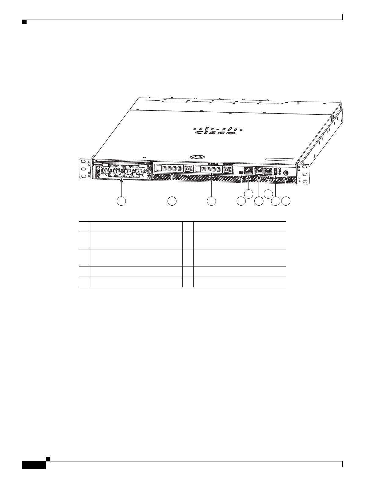
Figure 1-1 shows the front panel components.
Figure 1-1 Front Panel
Chapter 1 Introducing the Cisco Wide Area Virtualization Engine 594 and 694
1 Interface Module slot 6 10/100/1000 GE 0/0 connector
2 Hard drive bay 1 (device number 0)7 10/100/1000 GE 0/1 connector
3 Hard drive bay 2 (device number 1)8 External USB port
4 Console port (mini-USB) 9 Power On button
5 Console port (RJ-45)
Cisco Wide Area Virtualization Engine 594 and 694 Hardware Installation Guide
1-2
OL-24619-02
Page 3
Chapter 1 Introducing the Cisco Wide Area Virtualization Engine 594 and 694
246570
1 2 3 4 5 6
9
7
8
Cisco
W
ide
Ar
ea
Vir
t
ualiza
t
ion Engine
594
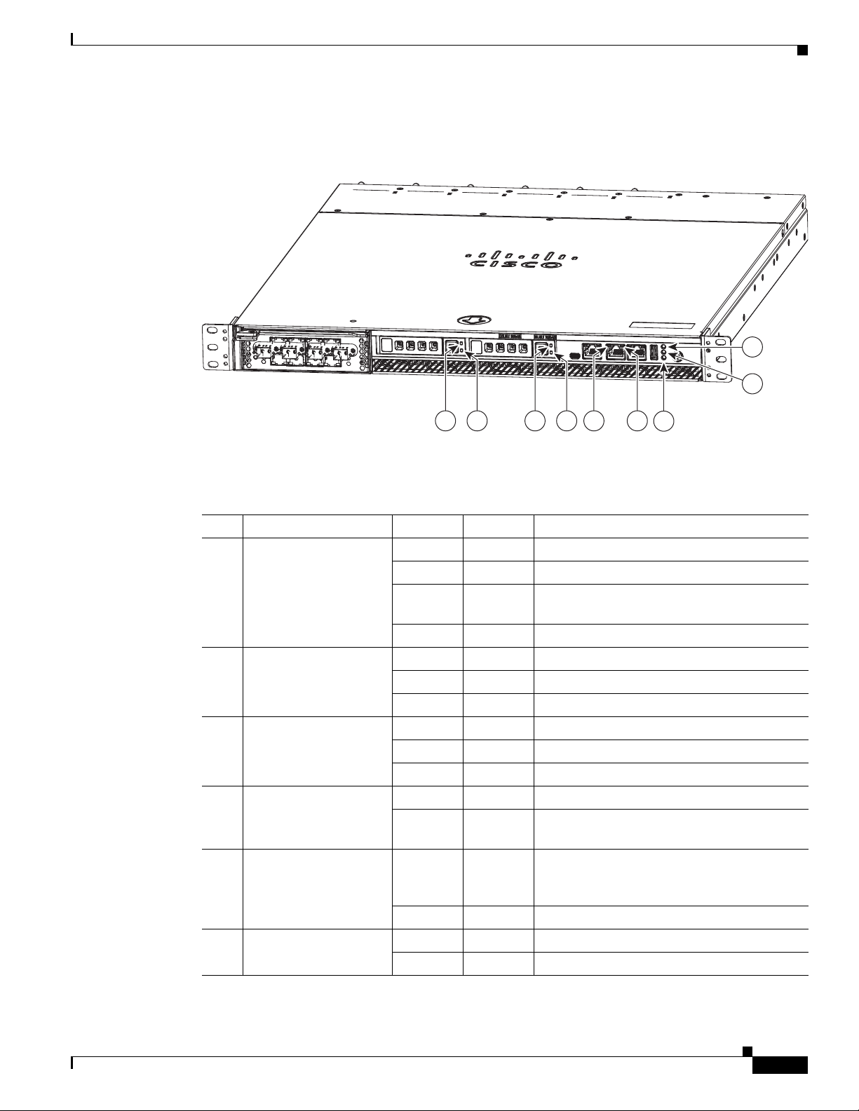
Figure 1-2 shows the front panel LEDs.
Figure 1-2 Front Panel LEDs
Hardware Features
Table 1-1 describes the front panel LEDs and their functions.
Table 1-1 Front Panel LEDs
LED Color State Description
1,3 Drive activity LED Green Blinking Drive activity is normal.
Green On Online.
Green Blinking
Drive locate.
1Hz
— Off No reading/writing, no activity.
5 NIC link/activity Green On Link exists.
Green Blinking Activity exists.
— Off No link detected.
6 NIC speed — Off 10Mbps connection.
Green On 100Mbps connection.
Yellow On 1000Mbps connection.
7 System power LED Green On System is on.
— Off Power cord is not attached or power supply
failure has occurred.
8 System fault LED Yellow On System has detected a fault. Refer to the
“Troubleshooting the System Hardware”
chapter for more information.
— Off System operation is normal.
9 Storage activity LED Green Blinking Drive activity is normal.
Orange On Drive failure has occurred.
OL-24619-02
Cisco Wide Area Virtualization Engine 594 and 694 Hardware Installation Guide
1-3
Page 4

Hardware Features
1 2 3 4 5 6 7 8
1 2 3 4 5 6 7 8
Back Panel Components and LEDs
Figure 1-3 shows the back panel components.
Note To monitor the boot process in normal operation, use a console port.
Figure 1-3 Back Panel Components
1 Power supply 1 5 Fan 4
2 Power supply 0 6 Fan 3
3 Fan 6 7 Fan 2
4 Fan 5 8 Fan 1
Chapter 1 Introducing the Cisco Wide Area Virtualization Engine 594 and 694
Figure 1-4 shows the back panel LEDs.
Figure 1-4 Back Panel LEDs
Table 1-2 describes the back panel LEDs and their functions.
Ta b le 1 - 2 B ac k P a ne l L E D s
LED Color State Description
1, 2 Power supply status — Off No AC power to all power supplies.
Red Blinking No AC power to this power supply.
Green Blinking AC power is present, only standby output on.
Green On Power supply DC outputs on and OK.
Red On Power supply failure. Refer to the
“Troubleshooting the System Hardware”
chapter for more information.
Cisco Wide Area Virtualization Engine 594 and 694 Hardware Installation Guide
1-4
OL-24619-02
Page 5

Chapter 1 Introducing the Cisco Wide Area Virtualization Engine 594 and 694
Table 1-2 Back Panel LEDs (continued)
LED Color State Description
3 - 8 Fan status Orange On Alarm.
Orange Blinking Alarm. Fan speed too low.
— Off Normal state.
Location of Ports and Connectors
The WAVE appliance supports two Ethernet connectors and two Console ports on the front of the
appliance.
Figure 1-3 shows the back panel ports and connectors.
Hardware Features
Warning
To avoid electric shock, do not connect safety extra-low voltage (SELV) circuits to telephone-network
voltage (TNV) circuits. LAN ports contain SELV circuits, and WAN ports contain TNV circuits. Some
LAN and WAN ports both use RJ-45 connectors. Use caution when connecting cables.
This section contains the following topics:
• Ethernet Port Connectors
• Console Port Connector
Ethernet Port Connectors
Connect a Category 3, 4, or 5 unshielded twisted-pair cable to an Ethernet connector. 100BASE-TX and
1000BASE-T Fast Ethernet standards require Category 5 or higher cabling.
The WAVE-594 and WAVE-694 appliance has two Ethernet connectors that are attached to the Ethernet
controllers (see Figure 1-5). The Ethernet controllers are integrated on the system board. They provide
an interface for connecting to a 10-Mbps, 100-Mbps, or 1-Gbps network and provide full-duplex (FDX)
capability, which enables simultaneous transmission and reception of data on the network. If the
Ethernet ports in the server support auto negotiation, the controllers detect the data-transfer rate
(10BASE-T, 100BASE-TX, or 1000BASE-T) and duplex mode (full duplex or half duplex) of the
network and automatically operate at that rate and mode. You do not have to set any jumpers or configure
the controllers.
Note There is a third RJ45 connector on the front of the appliance (see Figure 1-1). This is a console port. Do
not connect this port to your network.
Statement 1021
OL-24619-02
Cisco Wide Area Virtualization Engine 594 and 694 Hardware Installation Guide
1-5
Page 6

Connecting a Console Terminal
Figure 1-5 Ethernet Port Connector
Chapter 1 Introducing the Cisco Wide Area Virtualization Engine 594 and 694
Link/Activity
LED
8
1
Console Port Connector
The WAVE-594 and WAVE-694 appliance has two console port connectors, serial and mini-USB (see
Figure 1-1). Use a console port connector to access the command-line interface (CLI) for controlling the
WAVE appliance.
For information on connecting a console terminal to the mini-USB console port, see the “Connecting a
Console Terminal” section on page 1-6.
Connecting a Console Terminal
The WAVE appliance has both serial and mini-USB console ports (see Figure 1-1). These ports provide
administrative access to your appliance with a console terminal or PC.
Speed LED
330210
Note You cannot use both ports at the same time. If both ports are connected, the mini-USB port takes priority.
Note When using the mini-USB port to connect to a Windows-based PC for the first time, you must install the
Windows USB driver on the PC first. See the “Installing the Cisco USB Driver” section on page 1-6.
Cabling
The following cables included with the WAVE appliance may be used for connecting the WAVE
appliance to a console terminal or PC:
• USB Console cable—5-pin USB to mini-USB Type A-B
• Serial Console cable— EIA RJ-45 to DB-9
Installing the Cisco USB Driver
When using the mini-USB port to connect a Microsoft Windows based PC as a console terminal to the
WAVE appliance, you must first install the Windows USB driver on the PC. Otherwise, the USB
interface may not function.
The following Windows operating systems are supported:
• Windows XP—32-bit and 64-bit
1-6
Cisco Wide Area Virtualization Engine 594 and 694 Hardware Installation Guide
OL-24619-02
Page 7

Chapter 1 Introducing the Cisco Wide Area Virtualization Engine 594 and 694
• Vista—32-bit, Business edition
• Vista—64-bit
• Windows 7—32-bit and 64-bit
To install the Cisco Microsoft Windows USB driver, perform the following steps:
Note Do not connect the cable from the Windows PC to the WAVE appliance until after the driver is installed.
Step 1 Load the DVD that came with your WAVE appliance and double-click the CUSBInst.exe file. The Cisco
Virtual Com InstallShield Wizard begins.
You can also access the driver from the WAAS software download area of Cisco.com located at:
http://www.cisco.com/cisco/pub/software/portal/select.html?&mdfid=280484571&catid=268437639&
softwareid=280836712
It’s located under release 4.4.1 and the filename is CUSBInst_Signed_18May2011.exe
Step 2 Click Next. The Ready to Install the Program window appears.
Step 3 Click Install. The InstallShield Wizard Completed window appears.
Step 4 Click Finish.
Step 5 Connect the USB cable to the PC USB port and WAVE appliance mini-USB console port. Within a few
moments, the Found New Hardware Wizard appears.
Connecting a Console Terminal
Follow the instructions to complete the installation of the driver.
Step 6 Once the installation is finished, the USB console is ready for use.
Note If the driver has been installed on the PC but does not get bound to the hardware, you can manually
browse the driver installation query to the location C:\Windows\tiinst\. The newly attached hardware will
appear in the Windows Device Manager as "TUSB3410 EECode Ser".
This solution also applies when connecting additional WAVE appliances to the same PC. Multiple WAVE
appliances can be independently administered by console sessions on the same PC.
Note You do not need to reinstall the driver if you change to a different USB port on your PC.
Note If you happen to install the driver multiple times, each time the driver is installed the virtual COM port
number assigned to the USB port gets incremented. This is expected behavior and may not get reset even
if you uninstall the driver.
OL-24619-02
Cisco Wide Area Virtualization Engine 594 and 694 Hardware Installation Guide
1-7
Page 8

Connecting a Console Terminal
Chapter 1 Introducing the Cisco Wide Area Virtualization Engine 594 and 694
1-8
Cisco Wide Area Virtualization Engine 594 and 694 Hardware Installation Guide
OL-24619-02
 Loading...