

Page 1
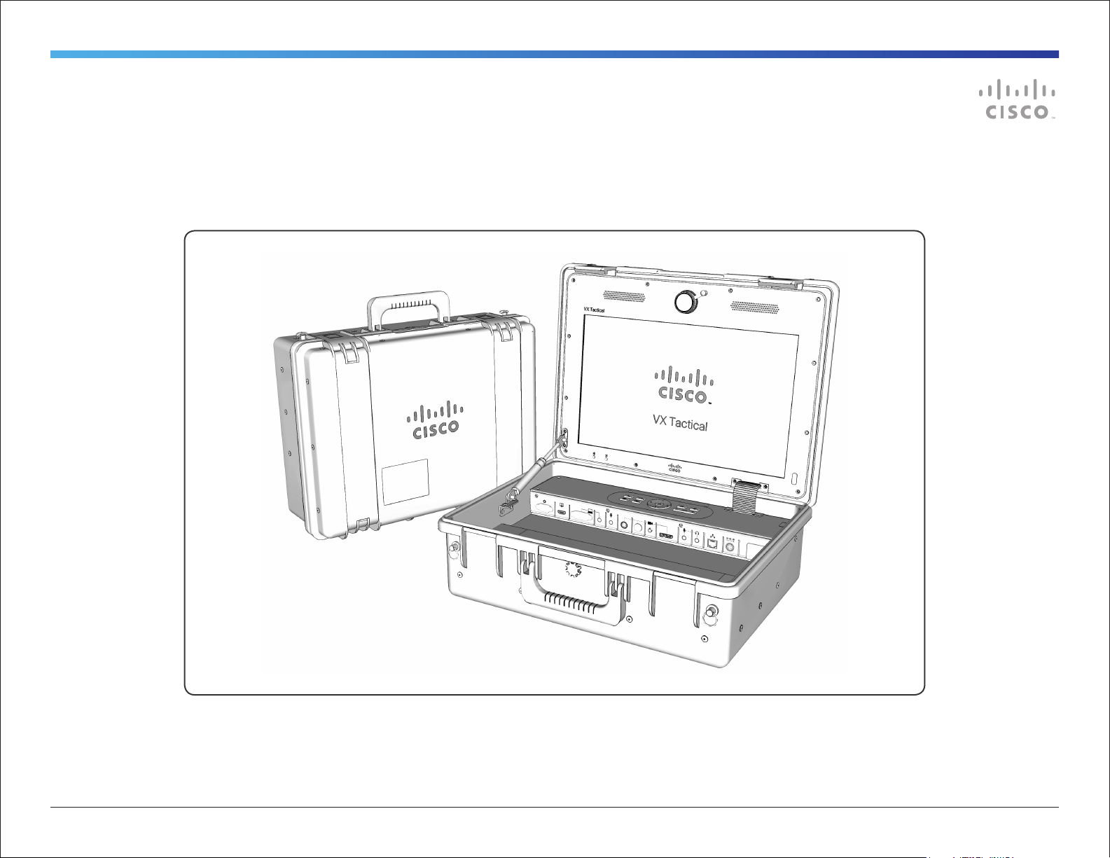
Cisco TelePresence VX Tactical
USER GUIDE FOR VX TACTICAL
VXD00101.01 Cisco TelePresence VX Tactical User Guide | 2012 MAY | © 2012 Cisco Systems, Inc. All rights reserved.
1
Page 2

Table of Contents
What’s in this guide?
Important Safety Instructions ....................................3
Operator Safety Summary ........................................4
Equipment Markings ..............................................4
Safety Precautions ....................................................5
Warning .................................................................5
Environmental Issues .............................................5
Waste Handling .....................................................5
Introduction ...............................................................6
System Overview ......................................................7
Display, Integrated Camera, Speakers, Microphone,
and IR Sensors .........................................................8
Installing the Optional I/O Cover ...............................9
I/O Interface Panel ..................................................10
Powering the System ..............................................11
Call Control Pad and Remote Control .....................12
Call Control Pad ..................................................12
Remote Control ...................................................12
Call Operation using the Call Control Pad ...............13
Answer an incoming call ......................................13
Disconnect or reject a call ...................................13
Place a call ..........................................................13
Add a call ............................................................13
Call Operation using the Remote Control ................14
Answer an incoming call ......................................14
Disconnect or reject a call ...................................14
Place a call from Directory ...................................14
Place an ad hoc call ............................................14
Add a call ............................................................14
Share Content .....................................................14
Cleaning the System ...............................................15
NOTE: The VX Tactical’s Cisco TelePresence SX20
Codec must first be provisioned and configured on an
appropriate network to place telepresence calls.
Please refer to the following URL for information about
provisioning, configuration, and operation of the SX20
Codec:
http://www.cisco.com/go/telepresence/docs
VXD00101.01 Cisco TelePresence VX Tactical User Guide | 2012 MAY | © 2012 Cisco Systems, Inc. All rights reserved.
2
Page 3

Important Safety Instructions
This warning symbol means danger. You are in a situation that
could cause bodily injury. Before you work on any equipment,
be aware of the hazards involved with electrical circuitry and be
familiar with standard practices for preventing accidents.
NOTE: SAVE THESE INSTRUCTIONS
NOTE: This documentation is to be used in conjunction with
the specific product installation guide that is shipped with the
product. Please refer to the Installation Guide, Configuration
Guide or other enclosed additional documentation for details.
Read the installation instructions/user manual before
connecting the system to the power source.
Ultimate disposal of this product should be handled according
to all national laws and regulations.
Power Cable and AC Adapter
When installing the product, please use the provided or
designated cables/power cables/AC adaptors. Using any
other cables/adaptors could cause a malfunction or a fire.
Electrical Appliance and Material Safety Law prohibits the use
of UL-certified cables (that have the “UL” shown on the code)
for any other electrical devices other than products designated
by CISCO. The use of cables that are certified by Electrical
Appliance and Material Safety Law (that have “PSE” shown on
the code) is not limited to CISCO-designated products.
VXD00101.01 Cisco TelePresence VX Tactical User Guide | 2012 MAY | © 2012 Cisco Systems, Inc. All rights reserved.
3
Page 4

Operator Safety Summary
For your protection, please read these safety
instructions completely before operating the equipment
and keep this manual for future reference. The
information in this summary is intended as general
guidance for those who operate the equipment as well
as repair (servicing) personnel. Carefully observe all
warnings, precautions and instructions on the system,
or the ones described in the operating instructions and
adhere to them.
Equipment Markings
● Cleaning - Unplug the system from the power source before
cleaning or polishing. Please adhere to the general cleaning
guidelines found in this document’s section: “Cleaning the
System.”
● Grounding- This equipment must be grounded. Never
defeat the ground conductor or operate the equipment
in the absence of a suitably installed ground conductor.
Contact the appropriate electrical inspection authority or
an electrician if you are uncertain that suitable grounding is
available.
● Power-Cord Protection - Route the power cord so as
to avoid it being walked on or pinched by items placed
upon or against it, paying particular attention to the plugs,
receptacles, and the point where the cord exits from the
system.
● Attachments - Only use attachments as recommended
by the manufacturer and in accordance to the system
guidelines in this document.
● Lightning - Unplug this system during lightning storms or
when unused for long periods of time.
● Servicing - Do not attempt to service the system yourself as
opening or removing covers may expose you to dangerous
voltages or other hazards, and will void the warranty. Refer
all servicing to qualified service personnel.
● Storage - If you need to store the system, ensure that it is
stored in a controlled environment to avoid damage. Refer
to the codec documentation for further guidelines.
● Mobility & Portability – Before moving the system it is
recommended that the power cord and other connected
equipment are unplugged and disconnected. Securely
close the case with its latches and use the carry handle to
transport the system to another location.
● Damaged Equipment - Unplug the system from the outlet
and refer servicing to qualified personnel under the
following conditions:
- When the power cord or plug is damaged or frayed
- If the system has been subjected to excessive shock by
being dropped, or the unit has been damaged
- If the system fails to operate in accordance with the
operating instructions.
VXD00101.01 Cisco TelePresence VX Tactical User Guide | 2012 MAY | © 2012 Cisco Systems, Inc. All rights reserved.
4
Page 5
Safety Precautions
Warning
While this system is designed for portability and
durability, users should use precaution during use and
transportation of the system to ensure their safety and
prevent damage to the unit.
For Customers In North America
This equipment complies to the limits for a Class A
digital device, pursuant to Part 15 of the FCC Rules.
These limits are designed to provide reasonable
protection against harmful interference when the
equipment is operated in a commercial environment.
This equipment generates, uses, and can radiate
radio frequency energy, which may cause harmful
interference to radio communications.
You are cautioned that any changes or modifications
not expressly approved in this manual could void your
authority to operate this equipment
Environmental Issues
Thank you for buying a product, which contributes
to a reduction in pollution, and thereby helps save
the environment. Our products reduce the need for
travel and transport and thereby reduce pollution. Our
products have either none or few consumable parts
(chemicals, toner, gas, paper). Our products are low
energy consuming products.
Battery handling
Batteries for the Remote Control are Long Life Alkaline
batteries; please follow guidelines on the packing
material for handling and disposal of the batteries.
Production of Products
Our factories employ efficient environmental methods
for reducing waste and pollution and ensuring the
products are recyclable.
Waste Handling
EU Battery and WEEE Directives
Your Cisco product may contain a user replaceable
battery or a permanently affixed battery as indicated in
the user manual. For product safety and data integrity
reasons a permanently affixed battery should only
be removed or replaced professionally by a repair
technician or waste management professional. Please
contact Cisco or an authorized service agent if the
product fails to perform due to malfunction of the
permanently affixed battery.
This symbol on a Cisco product, battery or
packaging means that the product and/or
battery should not be disposed of with
your household waste.
It is your responsibility to dispose of your waste
equipment and batteries separately from your
household waste and in accordance with local laws and
regulations. The correct disposal of your old equipment
and batteries will help prevent potential negative
consequences for the environment and human health.
VXD00101.01 Cisco TelePresence VX Tactical User Guide | 2012 MAY | © 2012 Cisco Systems, Inc. All rights reserved.
Please use the nearest waste collection facility as
directed by your municipality or your retailer.
5
Page 6

Introduction
The VX Tactical puts the power of TelePresence into a
compact and mobile solution. Designed for portability
and ease of use the VX Tactical is a high-definition video
collaboration system with functionality that facilitates
remote communication and collaboration.
This portable endpoint is part of the Cisco TelePresence
portfolio, which offers video recording, firewall traversal,
and video management capabilities. The VX Tactical
can help overcome the barrier of distance by enabling
effective collaboration in any setting.
Key Features of VX Tactical:
● Water-, sand-, impact-, chemical- and corrosion-
resistant case providing portability, durability and
functionality.
● Cisco TelePresence SX20 codec featuring high-
definition (HD) video and content sharing with fullduplex audio.
● Embedded 1080p HD camera and integrated
speakers and microphone
● Sunlight readable, optically bonded, 17.5-inch
720p60 HD display that is 3x stronger than standard
screens.
● Tactile control panel offering simplified system
control and a tethered infrared remote control for full
system operation
● AC and DC power options for system operation
● Security hasps (2x) for securing the unit.
WEIGHT:
26.7 lbs
12.1 kg
DIMENSIONS:
D 7.3” (18.54 cm)
W 19.2” (48.77 cm)
L 15.2” (38.6 cm)
OPENED: 20” (51cm)
VXD00101.01 Cisco TelePresence VX Tactical User Guide | 2012 MAY | © 2012 Cisco Systems, Inc. All rights reserved.
6
Page 7

System Overview
Zippered Storage Pouch
with Fastening Strap
Security Hasp (2x)
Optically-bonded 17.5” diagonal
HD, Sunlight Readable Display
Display Brightness Controls
Call Control Pad
Gas
Shock
Integrated 1080p Camera
with attached Protective Cover
Press and Pull Latch (2x)
Integrated
Speakers (2x)
Infrared Receiver and
“Case Closed” Sensor
I/O Interface Panel
with Optional Protective Cover
Remote Control Storage
Soft-grip
Handle
Impact, Sand, and
Water Resistant Case
Tethered TRC
Remote Control
VXD00101.01 Cisco TelePresence VX Tactical User Guide | 2012 MAY | © 2012 Cisco Systems, Inc. All rights reserved.
Integrated
Microphone
Hook and Loop Fastening Strap
Storage Area with
Equipment Labeling
at Right
Padded Nylon Strap
with Spring Clips
7
Page 8

Display, Integrated Camera, Speakers, Microphone, and IR Sensors
Display
When powering on the system, the HD 17.5” (44.45 cm)
sunlight-readable display will show a static image of the Cisco
VX Tactical logo during codec boot up. This will persist onscreen until the system’s codec has booted up fully.
The display is optically bonded making it much stronger than
standard screens and provides a highly impact resistant screen
able to endure relatively harsh environments.
Brightness Control
Use the Brightness Control buttons to adjust the display’s
brightness to suit the environment.
1080p 1/3-inch CMOS camera with cover.
Gently turn the embedded camera clockwise or counter-clockwise to manually
adjust focus.
Integrated waterproof stereo speakers (2x)
Embedded Camera
The 1080p 1/3” CMOS camera can be manually focused by
gently turning the camera to the left or right.
Integrated Speakers
System audio is heard through the waterproof stereo speakers.
Connecting a headset into the HEADSET jack will switch system
audio from the speakers to the headset.
Embedded System Microphone
The embedded microphone is used to capture audio from local
users. Connecting to MIC2 will supplement the call utilizing
both the system mic and the secondary mic. Connecting a mic
into headset MIC1 will switch the system mic off and enable the
audio to be heard though MIC1 (and MIC2 if connected).
IR Sensors
The IR sensor at the corner of the display is used to receive
commands from the tethered remote control.
The IR sensor found atop the interface panel triggers the
display to enter “standby mode” when the case is closed. Both
IR sensors must be clear of obstruction in order for the display
to enter standby.
NOTE: Closing the case will disconnect all calls.
Display
brightness
controls
Sunlight readable, optically
bonded, 17.5-inch diagonal
720p60 HD display that is
stronger than standard screens.
IR sensor
for remote
control
“Case
Closed” IR
sensor
Embedded
system
microphone
VXD00101.01 Cisco TelePresence VX Tactical User Guide | 2012 MAY | © 2012 Cisco Systems, Inc. All rights reserved.
8
Page 9

Installing the Optional I/O Cover
An optional I/O Cover is included and may be installed
to provide additional protection of the connectors found
on the Interface Panel.
Interface Panel
I/O Cover
1. Align the four (4) screw holes along the top of
the Interface Panel with the I/O Cover and its
corresponding holes.
2. Use a small Phillips screwdriver to secure the
provided screws (4) to the holes on the Interface
Panel.
To remove the I/O Cover, use a small Phillips
screwdriver to remove the four (4) screws and pull the
cover away from the system.
Store in a safe place if ever the I/O Cover should be
needed again.
VXD00101.01 Cisco TelePresence VX Tactical User Guide | 2012 MAY | © 2012 Cisco Systems, Inc. All rights reserved.
9
Page 10

I/O Interface Panel
Serial Port
Administrative use only. Used
for firmware upgrades and
diagnostics. Only connect
when instructed by certified Cisco
technician. NOTE: This not a
connection to the Codec.
HDMI Display Out
Connect a second display to
HDMI OUT (e.g., for viewing on
a larger screen).
Display output (HDMI 2) is configurable
via system menus: SETTINGS >
ADMINISTRATOR SETTINGS > ADVANCED
CONFIGURATION > VIDEO > OUTPUT >
HDMI 2 using the Navigation Buttons.
PC (DVI-I In / Audio In)
Use the DVI-I
connection to share
content from a
computer or other device to the VX
Tactical screen and/or with remote
participants.
PC Audio can be added by plugging in a
3.5mm audio plug.
Microphone 2 In
Connect a secondary room
microphone to enhance the
telepresence call.
NOTE: MIC2 audio can still be heard
when a headset microphone is
connected to MIC.
If using the optional Cisco Performance
Mic 20 microphone, the Mute Button will
mute ALL system microphones, as will
the Mute Button on the TRC Remote.
Camera (Video) In
When the
system
detects
video from an alternate Camera video
source, it will override the integrated VX
Tactical camera. If there is no alternate
source detected the system camera will
be active.
The order of priority for alternate
sources begin with the HDMI connection.
Camera control is available if using a
Cisco Precision HD Camera.
The second and third priorities go to
the Composite input and to the S-Video
input respectively.
System Microphone
This is an
embedded
microphone
to pick up audio from local users.
Headset and Microphone In
Connect a headset with
microphone to the 3.5mm
input to provide audio
privacy in a public setting or clarity in a
noisy environment.
The audio will be diverted from the VX
Tactical speakers and will be heard only
through the connected headset.
When a headset microphone is
connected to MIC input, the embedded
mic will be turned off. Audio from MIC2,
if connected, can still be heard when a
headset microphone is connected.
NOTE: This microphone input is
designed for a 3-Pin 3.5mm connection.
Network In
Use the Ethernet connection to
provide network for the VX
Tactical.
DC Power In (Secondary)
The 12V DC Power 4-Pin DIN
connection provides alternate
power to the VX Tactical when AC
Power (Primary) is not available. A DCDC Convertor is provided to
accommodate 12~32V DC.
AC Power In (Primary)
Provide power to the VX
Tactical using 100~240V AC
50-60Hz.
VXD00101.01 Cisco TelePresence VX Tactical User Guide | 2012 MAY | © 2012 Cisco Systems, Inc. All rights reserved.
10
Page 11

Powering the System
The VX Tactical provides two options for powering the
system.
NOTE:
The system will not operate unless connected to an
appropriate power source.
DC-DC Power
Convertor
AC Power In (Primary)
Provide power to the VX Tactical using
100~240V AC 50-60Hz. Use a country
specific plug/adapter to supply power.
DC Power In (Secondary)
The 12V DC Power 4-Pin DIN connection
provides alternate power to the VX Tactical when
AC Power (Primary) is not available. A DC-DC
Convertor is provided to accommodate 12~32V DC.
NOTE:
AC Power takes priority when both AC and DC power
are connected -- the DC inlet will switch off when AC
power is present. DC power will switch on when AC
power is absent.
Power
Inlets
DC Adapter Plug
(12~32V DC)
AC Plug (country specific)
100~240V AC 50-60Hz
WARNING!
Closing the lid on cables running out of the
system may sever or damage the cables!
VXD00101.01 Cisco TelePresence VX Tactical User Guide | 2012 MAY | © 2012 Cisco Systems, Inc. All rights reserved.
11
Page 12

Call Control Pad and Remote Control
Lift the magnetic cover
to access the tethered
remote control.
Call Control Pad
The VX Tactical features a simplified Call Control
interface for quick operation and ease of use.
The green CALL button initiates a call,
The red DISCONNECT button ends a call.
The DIRECTORY button pulls up the manually
maintained local directory menu and any
remote corporate directories.
Press SELFVIEW to see what others will see
from your camera when in a call.
The HOME button shows and hides the main
menu.
MIC MUTE switches all connected
microphones on and off.
The VOLUME CONTROL adjusts
audio levels from the system.
The NAVIGATION and OK buttons enable you
to navigate the system’s menu structure.
Remote Control
The tethered remote control is housed under a
magnetically latched cover. Lift the cover to access the
remote control.
The retractable tether can extend up to 4’ (121.92 cm).
To retract the remote, slightly pull the tether to release
the catch and slowly return the remote control to its
storage area.
NOTE: Detailed instructions for operating the Cisco
Telepresence Remote Control can be found:
http://www.cisco.com/go/telepresence/docs
VXD00101.01 Cisco TelePresence VX Tactical User Guide | 2012 MAY | © 2012 Cisco Systems, Inc. All rights reserved.
12
Page 13

Call Operation using the Call Control Pad
The VX Tactical’s Call Control Pad has been designed
to make receiving and placing a call quick and simple.
Answer an incoming call
Press the green Call Button to answer an
incoming call. The call will then use the built-
in speakers or connected headset.
When in a call
Press SELFVIEW to see what others will see
from your camera when in a call.
MIC MUTE switches all connected
microphones on and off.
The VOLUME CONTROL adjusts
audio levels from the system.
Disconnect or reject a call
Press the red DISCONNECT button to
terminate a call or reject an incoming call.
Place a call
Press the DIRECTORY button to display the
directory listing. Please note that all locally
created directory entries are stored under “My
Contacts.” Additional directory entries will also be
available if the system is configured on a network that
can access them.
NOTE: Accessing corporate directories must be made
available by a system administrator.
Use the NAVIGATION button to find and
select the directory entry to call.
Press the OK button or the green CALL
button to place the call.
NOTE: It is recommended that the “My Contacts”
directory is pre-populated using the Remote Control.
The simplified Call Control Pad limits the ability
to create directory entries or enter numbers and
characters to place a call “on-the-fly” without the aid
of the tethered Remote Control.
Add a call
The VX Tactical can support up to three (3) additional
video participants to a telepresence call with the
MultiSite option enabled.
Add a call from Directory
When in a call, you may choose to add
another participant by pressing the
DIRECTORY button, using the NAVIGATION button to
select the desired participant, and pressing either OK
button or the green CALL button to add a call.
You may connect up to three (3) video participants and
one (1) audio participant to your telepresence session
if MultiSite is enabled for your system.
Add an incoming call
While in a call and a call request is
presented, press the green CALL button to
answer that incoming call.
Press the red DISCONNECT button to reject
an incoming call.
TIP: When not in a call and all menus are closed,
press the green CALL button to show the “Recent
Calls” list.
VXD00101.01 Cisco TelePresence VX Tactical User Guide | 2012 MAY | © 2012 Cisco Systems, Inc. All rights reserved.
13
Page 14

Call Operation using the Remote Control
While the operation principles are similar
for the system’s Call Control Pad and the
Remote Control, the provided tethered
Remote Control enables greater control of
the VX Tactical’s capabilities beyond what
the Call Control Pad provides.
The following page shows an overview
of the Remote Control’s buttons and
functions. Please refer to the Remote
Control Guide for detailed instruction on
remote control operation.
Answer an incoming call
Press the green CALL button to answer an
incoming call. The call will then use the
built-in speakers or connected headset.
When in a call
Press SELFVIEW to see what others will see
from your camera when in a call. Press again
to show Main Camera,
MIC MUTE switches all connected
microphones on and off. Press again to
toggle Mic On.
The VOLUME CONTROL adjusts audio levels
from the system.
Disconnect or reject a call
Press the red DISCONNECT button to
terminate a call or reject an incoming call.
Place a call from Directory
Press the DIRECTORY Button to display the
directory listing. Please note that all locally
created directory entries are stored under
“My Contacts.” Additional directory entries will also be
available if the system is configured on a network that
can access them.
NOTE: Accessing corporate directories must be made
available by a system administrator.
Use the NAVIGATION button to find and
select the directory entry to call.
Press the OK button or the green CALL
button to place the call.
Place an ad hoc call
Press the HOME button or the OK button to
bring up the Onscreen Menu and select Call.
Use the ALPHANUMERIC KEYPAD to enter a
number or URI and press the green CALL
button to place the call.
Add a call
When in a call, you may choose to add another
participant by pressing the DIRECTORY button to select
the desired participant, or enter a number or URI using
the ALPHANUMERIC KEYPAD, and pressing either OK
button or the green CALL button to add a call.
The VX Tactical may connect up to three (3)
participants and one (1) audio only call to the
telepresence session if MultiSite is enabled for your
system.
Add an incoming call
While in a call and a call request is
presented, press the green CALL button to
answer that incoming call.
Press the red DISCONNECT button to reject
an incoming call.
Share Content
Pressing the PRESENTATION button will
share the contents of a connected PC.
Pressing the button again will switch back
to showing the Main Camera source.
VXD00101.01 Cisco TelePresence VX Tactical User Guide | 2012 MAY | © 2012 Cisco Systems, Inc. All rights reserved.
14
Page 15

Cleaning the System
In general, the unit’s case material can be cleaned
simply with a mild household detergent. As the case
is a plastic product, stiff brushes should be avoided in
cleaning the case, as these may scratch the surface.
NOTE: Scratches on the surface of the case will in no
way impede its performance.
Please adhere to your organization’s guidelines or
protocol for handling and cleaning contaminated
instruments.
1. Turn the system off -- Disconnect all power cords
and adaptors from the electrical power source.
2. Wipe the unit with a clean, soft cloth dampened
with a diluted mixture of mild detergent and water.
Squeeze out excess liquid from the cloth.
3. Wipe again with clean, soft cloth dampened with
clean water and wipe dry with clean, soft cloth.
NOTE: Use of certain detergents may cause
degradation to the labels and plastic components.
Consult detergent manufacturer to see if the product is
compatible.
NOTE: Do not allow liquid to enter into the display.
VXD00101.01 Cisco TelePresence VX Tactical User Guide | 2012 MAY | © 2012 Cisco Systems, Inc. All rights reserved.
15
Page 16

THE SPECIFICATIONS AND INFORMATION REGARDING THE PRODUCTS IN THIS MANUAL ARE SUBJECT TO
CHANGE WITHOUT NOTICE. ALL STATEMENTS, INFORMATION, AND RECOMMENDATIONS IN THIS MANUAL ARE
BELIEVED TO BE ACCURATE BUT ARE PRESENTED WITHOUT WARRANTY OF ANY KIND, EXPRESS OR IMPLIED.
USERS MUST TAKE FULL RESPONSIBILITY FOR THEIR APPLICATION OF ANY PRODUCTS.
On our web site you will find an overview of the worldwide
Cisco contacts.
Go to: http://www.cisco.com/web/siteassets/contacts
THE SOFTWARE LICENSE AND LIMITED WARRANTY FOR THE ACCOMPANYING PRODUCT ARE SET FORTH IN
THE INFORMATION PACKET THAT SHIPPED WITH THE PRODUCT AND ARE INCORPORATED HEREIN BY THIS
REFERENCE. IF YOU ARE UNABLE TO LOCATE THE SOFTWARE LICENSE OR LIMITED WARRANTY, CONTACT YOUR
CISCO REPRESENTATIVE FOR A COPY.
The Cisco implementation of TCP header compression is an adaptation of a program developed by the University of
California, Berkeley (UCB) as part of UCB’s public domain version of the UNIX operating system. All rights reserved.
Copyright © 1981, Regents of the University of California.
NOTWITHSTANDING ANY OTHER WARRANTY HEREIN, ALL DOCUMENT FILES AND SOFTWARE OF THESE
SUPPLIERS ARE PROVIDED “AS IS” WITH ALL FAULTS. CISCO AND THE ABOVE-NAMED SUPPLIERS DISCLAIM
ALL WARRANTIES, EXPRESSED OR IMPLIED, INCLUDING, WITHOUT LIMITATION, THOSE OF MERCHANTABILITY,
FITNESS FOR A PARTICULAR PURPOSE AND NONINFRINGEMENT OR ARISING FROM A COURSE OF DEALING,
USAGE, OR TRADE PRACTICE.
IN NO EVENT SHALL CISCO OR ITS SUPPLIERS BE LIABLE FOR ANY INDIRECT, SPECIAL, CONSEQUENTIAL, OR
INCIDENTAL DAMAGES, INCLUDING, WITHOUT LIMITATION, LOST PROFITS OR LOSS OR DAMAGE TO DATA
ARISING OUT OF THE USE OR INABILITY TO USE THIS MANUAL, EVEN IF CISCO OR ITS SUPPLIERS HAVE BEEN
ADVISED OF THE POSSIBILITY OF SUCH DAMAGES.
Cisco and the Cisco Logo are trademarks of Cisco Systems, Inc. and/or its affiliates in the U.S. and other countries. A
listing of Cisco’s trademarks can be found at www.cisco.com/go/trademarks. Third party trademarks mentioned are
the property of their respective owners. The use of the word partner does not imply a partnership relationship between
Cisco and any other company. (1005R)
Any Internet Protocol (IP) addresses and phone numbers used in this document are not intended to be actual
addresses and phone numbers. Any examples, command display output, network topology diagrams, and other
figures included in the document are shown for illustrative purposes only. Any use of actual IP addresses or phone
numbers in illustrative content is unintentional and coincidental.
Cisco Systems, Inc.
170 West Tasman Dr.
San Jose, CA 95134 USA
Cisco and the Cisco Logo are trademarks of Cisco Systems, Inc. and/or its affiliates in the U.S. and other countries. A listing of Cisco’s trademarks can be found at www.cisco.com/go/trademarks. Third-party trademarks mentioned are the property of
their respective owners. The use of the word partner does not imply a partnership relationship between Cisco and any other company. (1007R)
 Loading...