

Page 1

Cisco UCS Servers RAID Guide
Updated: February 06, 2018
Americas Headquarters
Cisco Systems, Inc.
170 West Tasman Drive
San Jose, CA 95134-1706
USA
http://www.cisco.com
Tel: 408 526-4000
800 553-NETS (6387)
Fax: 408 527-0883
Text Part Number: OL-26591-01
Page 2

THE SPECIFICATIONS AND INFORMATION REGARDING THE PRODUCTS IN THIS MANUAL ARE SUBJECT TO CHANGE WITHOUT NOTICE. ALL
STATEMENTS, INFORMATION, AND RECOMMENDATIONS IN THIS MANUAL ARE BELIEVED TO BE ACCURATE BUT ARE PRESENTED WITHOUT
WARRANTY OF ANY KIND, EXPRESS OR IMPLIED. USERS MUST TAKE FULL RESPONSIBILITY FOR THEIR APPLICATION OF ANY PRODUCTS.
THE SOFTWARE LICENSE AND LIMITED WARRANTY FOR THE ACCOMPANYING PRODUCT ARE SET FORTH IN THE INFORMATION PACKET THAT
SHIPPED WITH THE PRODUCT AND ARE INCORPORATED HEREIN BY THIS REFERENCE. IF YOU ARE UNABLE TO LOCATE THE SOFTWARE LICENSE
OR LIMITED WARRANTY, CONTACT YOUR CISCO REPRESENTATIVE FOR A COPY.
The following information is for FCC compliance of Class A devices: This equipment has been tested and found to comply with the limits for a Class A digital device, pursuant
to part 15 of the FCC rules. These limits are designed to provide reasonable protection against harmful interference when the equipment is operated in a commercial
environment. This equipment generates, uses, and can radiate radio-frequency energy and, if not installed and used in accordance with the instruction manual, may cause
harmful interference to radio communications. Operation of this equipment in a residential area is likely to cause harmful interference, in which case users will be required
to correct the interference at their own expense.
The following information is for FCC compliance of Class B devices: This equipment has been tested and found to comply with the limits for a Class B digital device, pursuant
to part 15 of the FCC rules. These limits are designed to provide reasonable protection against harmful interference in a residential installation. This equipment generates,
uses and can radiate radio frequency energy and, if not installed and used in accordance with the instructions, may cause harmful interference to radio communications.
However, there is no guarantee that interference will not occur in a particular installation. If the equipment causes interference to radio or television reception, which can be
determined by turning the equipment off and on, users are encouraged to try to correct the interference by using one or more of the following measures:
• Reorient or relocate the receiving antenna.
• Increase the separation between the equipment and receiver.
• Connect the equipment into an outlet on a circuit different from that to which the receiver is connected.
• Consult the dealer or an experienced radio/TV technician for help.
Modifications to this product not authorized by Cisco could void the FCC approval and negate your authority to operate the product.
The Cisco implementation of TCP header compression is an adaptation of a program developed by the University of California, Berkeley (UCB) as part of UCB’s public
domain version of the UNIX operating system. All rights reserved. Copyright © 1981, Regents of the University of California.
NOTWITHSTANDING ANY OTHER WARRANTY HEREIN, ALL DOCUMENT FILES AND SOFTWARE OF THESE SUPPLIERS ARE PROVIDED “AS IS” WITH
ALL FAULTS. CISCO AND THE ABOVE-NAMED SUPPLIERS DISCLAIM ALL WARRANTIES, EXPRESSED OR IMPLIED, INCLUDING, WITHOUT
LIMITATION, THOSE OF MERCHANTABILITY, FITNESS FOR A PARTICULAR PURPOSE AND NONINFRINGEMENT OR ARISING FROM A COURSE OF
DEALING, USAGE, OR TRADE PRACTICE.
IN NO EVENT SHALL CISCO OR ITS SUPPLIERS BE LIABLE FOR ANY INDIRECT, SPECIAL, CONSEQUENTIAL, OR INCIDENTAL DAMAGES, INCLUDING,
WITHOUT LIMITATION, LOST PROFITS OR LOSS OR DAMAGE TO DATA ARISING OUT OF THE USE OR INABILITY TO USE THIS MANUAL, EVEN IF CISCO
OR ITS SUPPLIERS HAVE BEEN ADVISED OF THE POSSIBILITY OF SUCH DAMAGES.
Cisco and the Cisco logo are trademarks or registered trademarks of Cisco and/or its affiliates in the U.S. and other countries. To view a list of Cisco trademarks, go to this
URL: www.cisco.com/go/trademarks. Third-party trademarks mentioned are the property of their respective owners. The use of the word partner does not imply a partnership
relationship between Cisco and any other company. (1110R)
Any Internet Protocol (IP) addresses and phone numbers used in this document are not intended to be actual addresses and phone numbers. Any examples, command display
output, network topology diagrams, and other figures included in the document are shown for illustrative purposes only. Any use of actual IP addresses or phone numbers in
illustrative content is unintentional and coincidental.
Cisco UCS Servers RAID Guide
© 2015 Cisco Systems, Inc. All rights reserved.
Page 3

CONTENTS
CHAPTER
1 RAID Overview 1-1
Information About RAID 1-1
Drive Group 1-1
Virtual Drive 1-1
Disk Striping 1-2
Disk Mirroring (RAID 1 and RAID 10) 1-2
Parity 1-3
Disk Spanning 1-3
Hot Spares 1-4
Global Hot Spare 1-5
Dedicated Hot Spare 1-5
Disk Rebuilds 1-6
Hot Swap 1-6
Drive States 1-7
Virtual Drive States 1-7
RAID Levels 1-8
RAID Levels Summary 1-8
RAID 0 1-9
RAID 1 1-10
RAID 5 1-10
RAID 6 1-12
RAID 00 1-13
RAID 10 1-14
RAID 50 1-15
RAID 60 1-16
Fault Tolerance 1-17
CHAPTER
OL-26591-01
Generic Drive Replacement Procedure 1-18
Removing a Drive from a Server 1-18
Installing a Drive in a Server 1-19
Platform-Specific RAID and Drive Procedures 1-19
2 Using Cisco Integrated Management Controller and Cisco UCS Server Configuration Utility for
RAID Monitoring and Configuring
2-1
Cisco Integrated Management Controller—Viewing Storage Properties 2-1
Cisco UCS Server Configuration Utility—RAID Configuration 2-2
Cisco UCS Servers RAID Guide
iii
Page 4

Contents
CHAPTER
3 Using Cisco UCS Manager for RAID Configuring and Monitoring 3-1
Cisco UCS Manager Configuration 3-1
Local Disk Configuration Policy 3-1
Guidelines for all Local Disk Configuration Policies 3-2
Guidelines for Local Disk Configuration Policies Configured for RAID 3-3
Creating a Local Disk Configuration Policy 3-4
Changing a Local Disk Configuration Policy 3-6
Deleting a Local Disk Configuration Policy 3-7
Server Disk Drive Monitoring 3-7
Support for Disk Drive Monitoring 3-7
Viewing the Status of a Disk Drive 3-8
Interpreting the Status of a Monitored Disk Drive 3-9
RAID Controllers in UCS Servers 3-10
Determining Which Controller is in Your Server 3-11
RAID Controllers 3-12
Disabling Quiet Boot 3-12
Accessing ROM-Based Controller Utilities 3-13
Documentation About RAID Controllers and LSI Utilities 3-13
Moving a RAID Cluster Using UCS Software Version 1.4(1) 3-13
Moving a RAID Cluster Using UCS Software Version 1.4(2) and Later Releases 3-14
Moving a RAID Cluster Between B200 M3 Servers 3-15
Replacing a Failed Drive in a RAID Cluster 3-16
CHAPTER
iv
4 Configuring the LSI SAS2 Integrated RAID Controller 4-1
Information about LSI Integrated RAID 4-1
Mirrored Volumes 4-3
Operation of Mirrored Volumes 4-3
Mirrored Volume Features 4-6
Mirroring and Mirroring Enhanced Features 4-7
Integrated Striping 4-8
Integrated Striping Features 4-9
Creating Mirrored Volumes 4-10
Launching the LSI SAS2 BIOS Configuration Utility 4-10
Creating Mirrored Volumes 4-11
Creating an Integrated Mirroring Volume 4-11
Creating an Integrated Mirroring Enhanced or Integrated Mirroring and Striping Volume 4-13
Expanding an Integrated Mirroring Volume with OCE 4-14
Managing Hot Spare Disks 4-15
Creating Hot Spare Disks 4-15
Cisco UCS Servers RAID Guide
OL-26591-01
Page 5

Deleting Hot Spare Disks 4-15
Other Configuration Tasks 4-16
Viewing Volume Properties 4-16
Running a Consistency Check 4-16
Activating an Array 4-17
Deleting an Array 4-17
Locating Disk Drives in a Volume 4-18
Choosing a Boot Disk 4-18
Creating Integrated Striping Volumes 4-19
Other Configuration Tasks 4-21
Viewing Volume Properties 4-21
Activating an Array 4-21
Deleting an Array 4-21
Locating Disk Drives in a Volume 4-22
Choosing a Boot Disk 4-23
Contents
CHAPTER
Determining Which Controller is in Your Server 4-23
Disabling Quiet Boot for CIMC Firmware Earlier than Release 1.2(1) 4-24
Launching Option ROM-Based Controller Utilities 4-24
Restoring RAID Configuration After Replacing a RAID Controller 4-25
5 LSI MegaRAID SAS Controller Tasks 5-1
LSI MegaRAID Controller Management Utilities 5-1
LSI WebBIOS Configuration Utility 5-1
MegaRAID Command Tool 5-2
MegaRAID Storage Manager 5-2
LSI WebBIOS CU 5-2
Starting the WebBIOS CU 5-2
WebBIOS CU Main Menu Window Options 5-3
Toolbar 5-4
Menu Options 5-4
Configuring RAID Drive Groups and Virtual Drives 5-5
Choosing the Configuration with the Configuration Wizard 5-5
Using Automatic Configuration 5-5
Using Manual Configuration 5-6
Viewing and Changing Device Properties 5-11
Viewing Controller Properties 5-11
Viewing Virtual Drive Properties, Policies, and Operations 5-13
Viewing Physical Drive Properties and Operations 5-14
Viewing and Changing Battery Backup Unit Information 5-15
OL-26591-01
Cisco UCS Servers RAID Guide
v
Page 6

Contents
Managing RAID 5-16
Expanding a Virtual Drive 5-16
Monitoring Array Health 5-16
Recovery 5-17
Deleting a Virtual Drive 5-18
Migrating an Array to a New Server 5-18
Foreign Configurations in Cable Pull and Drive Removal Scenarios 5-19
Importing Foreign Configurations from Integrated RAID to MegaRAID 5-20
Troubleshooting Information 5-20
Migrating the RAID Level of a Virtual Drive 5-20
Determining Which Controller is in Your Server 5-22
Disabling Quiet Boot for CIMC Firmware Earlier than Release 1.2(1) 5-22
Launching an Option ROM-Based Controller Utility 5-22
LSI MegaRAID Card Beep Codes 5-23
Restoring the RAID Configuration After Replacing a RAID Controller 5-23
CHAPTER
Limitation on Importing Foreign Configuration To a Virtual Disk That is Under Construction 5-25
Limitation 5-25
Design 5-25
Prerequisites For Reconstruction to Start 5-26
6 Configuring the Embedded ICH10R SATA Controller 6-1
Enabling the Integrated Intel ICH10R RAID Controller in the BIOS 6-1
Launching the LSI Software RAID Setup Utility 6-1
Configuring the Onboard Intel ICH10R RAID Controller 6-2
Creating a New RAID Configuration 6-3
Viewing or Changing a RAID Configuration 6-4
vi
Cisco UCS Servers RAID Guide
OL-26591-01
Page 7

RAID Overview
This chapter describes RAID (Redundant Array of Independent Disks), RAID functions and benefits,
RAID components, RAID levels, and configuration strategies.
This chapter contains the following sections:
• Information About RAID, page 1-1
• RAID Levels, page 1-8
• Generic Drive Replacement Procedure, page 1-18
• Platform-Specific RAID and Drive Procedures, page 1-19
Information About RAID
RAID is an array, or group, of multiple independent physical drives that provide high performance and
fault tolerance. A RAID drive group improves input/output (I/O) performance and reliability. The RAID
drive group appears to the host computer as a single storage unit or as multiple virtual units. I/O is
expedited because several drives can be accessed simultaneously.
RAID drive groups improve data storage reliability and fault tolerance compared to single-drive storage
systems. Data loss resulting from a drive failure can be prevented by reconstructing missing data from
the remaining drives. RAID improves I/O performance and increases storage subsystem reliability.
RAID levels describe a system for ensuring the availability and redundancy of data stored on large disk
subsystems. See RAID Levels, page 1-8 for detailed information about RAID levels. The RAID
drive-group components and RAID levels are described in the following sections.
CHA P T ER
1
Drive Group
Virtual Drive
OL-26591-01
A drive group is a group of physical drives. These drives are managed in partitions known as virtual
drives.
A virtual drive is a partition in a drive group that is made up of contiguous data segments on the drives.
A virtual drive can consist of an entire drive group, more than one entire drive group, a part of a drive
group, parts of more than one drive group, or a combination of any two of these conditions.
Cisco UCS Servers RAID Guide
1-1
Page 8
Information About RAID
Segment 1
Segment 5
Segment 9
Segment 2
Segment 6
Segment 10
Segment 3
Segment 7
Segment 11
Segment 4
Segment 8
Segment 12
332084
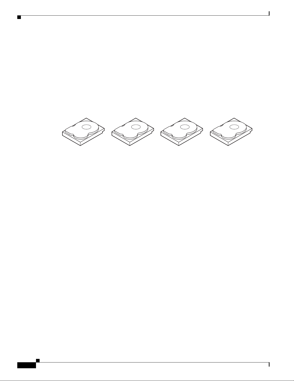
Disk Striping
Chapter 1 RAID Overview
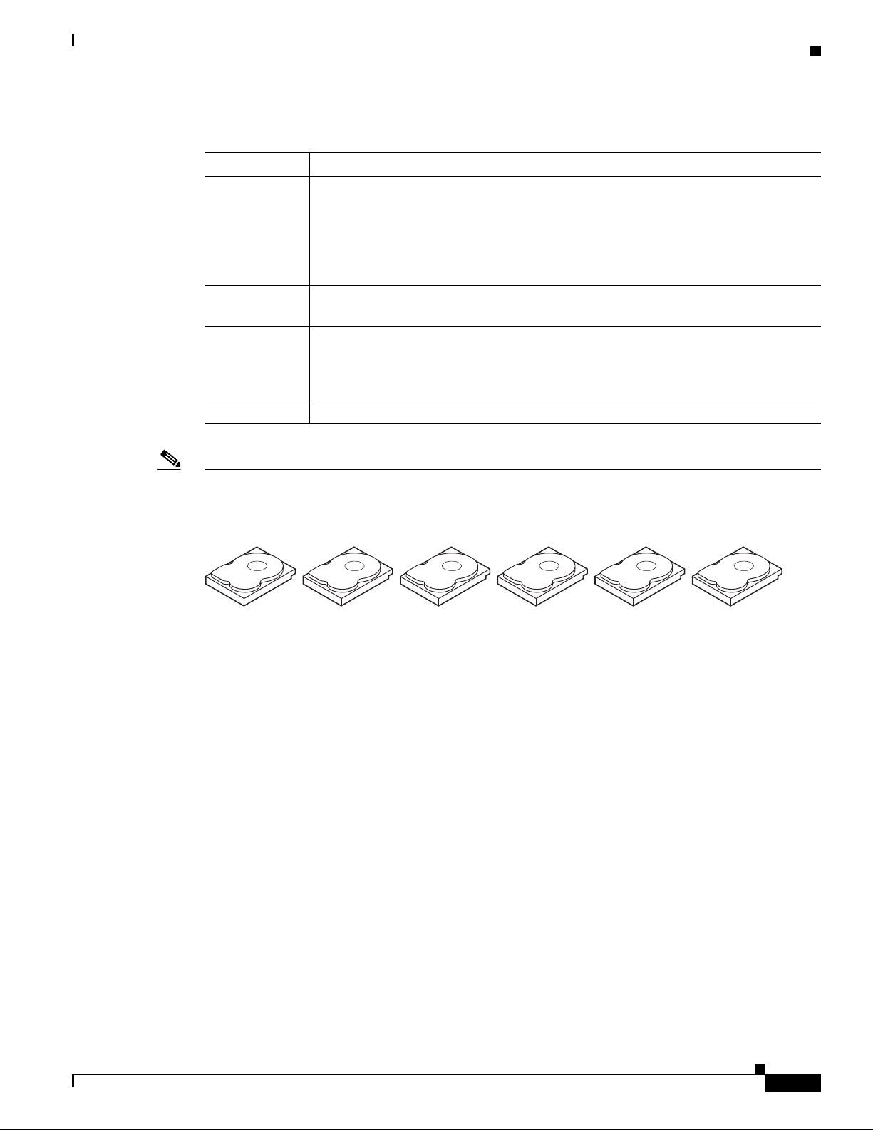
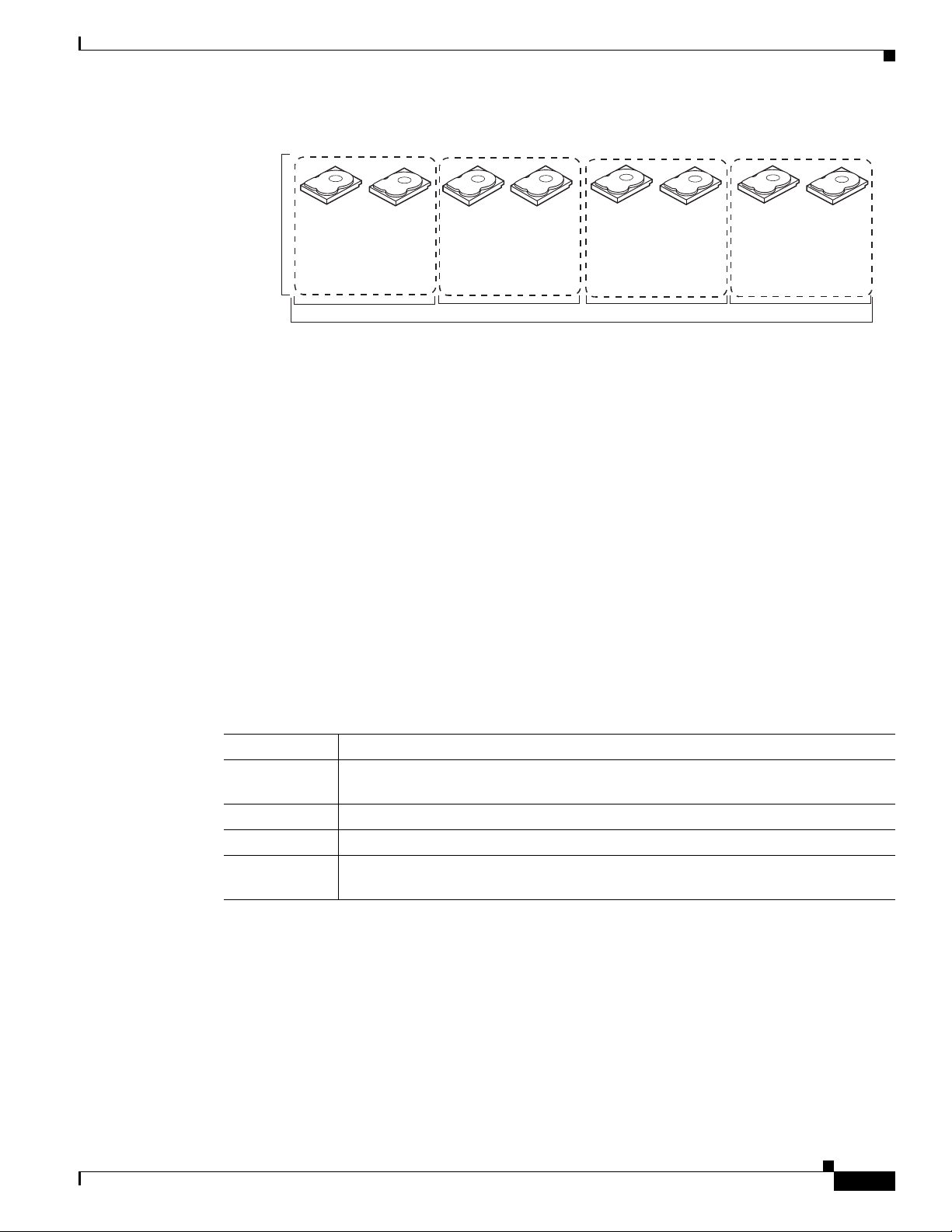
Disk striping (used in RAID level 0) allows you to write data across multiple drives instead of only one
drive. Disk striping involves partitioning each drive storage space into stripes that can vary in size from
8 KB to 1024 KB. These stripes are interleaved in a repeated sequential manner. The combined storage
space is composed of stripes from each drive. We recommend that you keep stripe sizes the same across
RAID drive groups.
For example, in a four-disk system using only disk striping, segment 1 is written to disk 1, segment 2 is
written to disk 2, and so on (see Figure 1-1). Disk striping enhances performance because multiple drives
are accessed simultaneously, but disk striping does not provide data redundancy
Figure 1-1 Example of Disk Striping (RAID 0)
Stripe width is the number of drives involved in a drive group where striping is implemented. For
example, a four-disk drive group with disk striping has a stripe width of four.
The stripe size is the length of the interleaved data segments that the RAID controller writes across
multiple drives, not including parity drives. For example, consider a stripe that contains 64 KB of disk
space and has 16 KB of data residing on each disk in the stripe. In this case, the stripe size is 64 KB and
the strip size is 16 KB.
The strip size is the portion of a stripe that resides on a single drive.
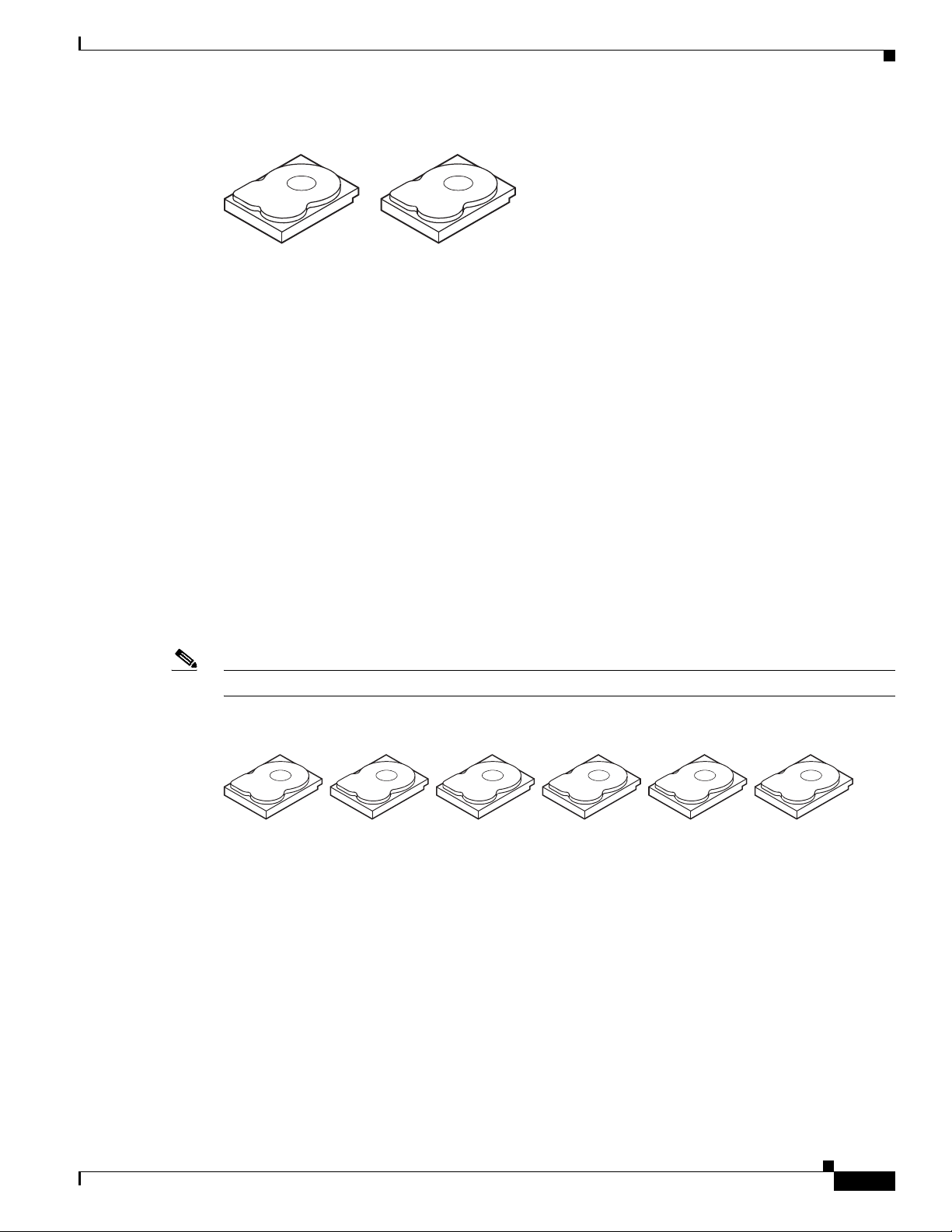
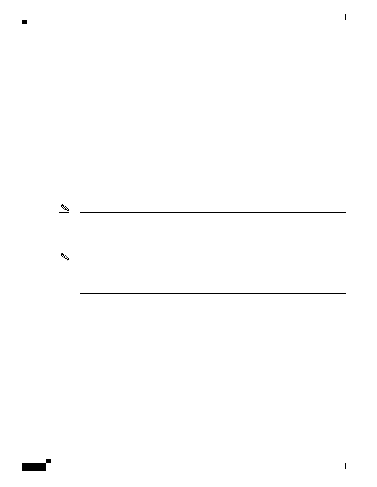
Disk Mirroring (RAID 1 and RAID 10)
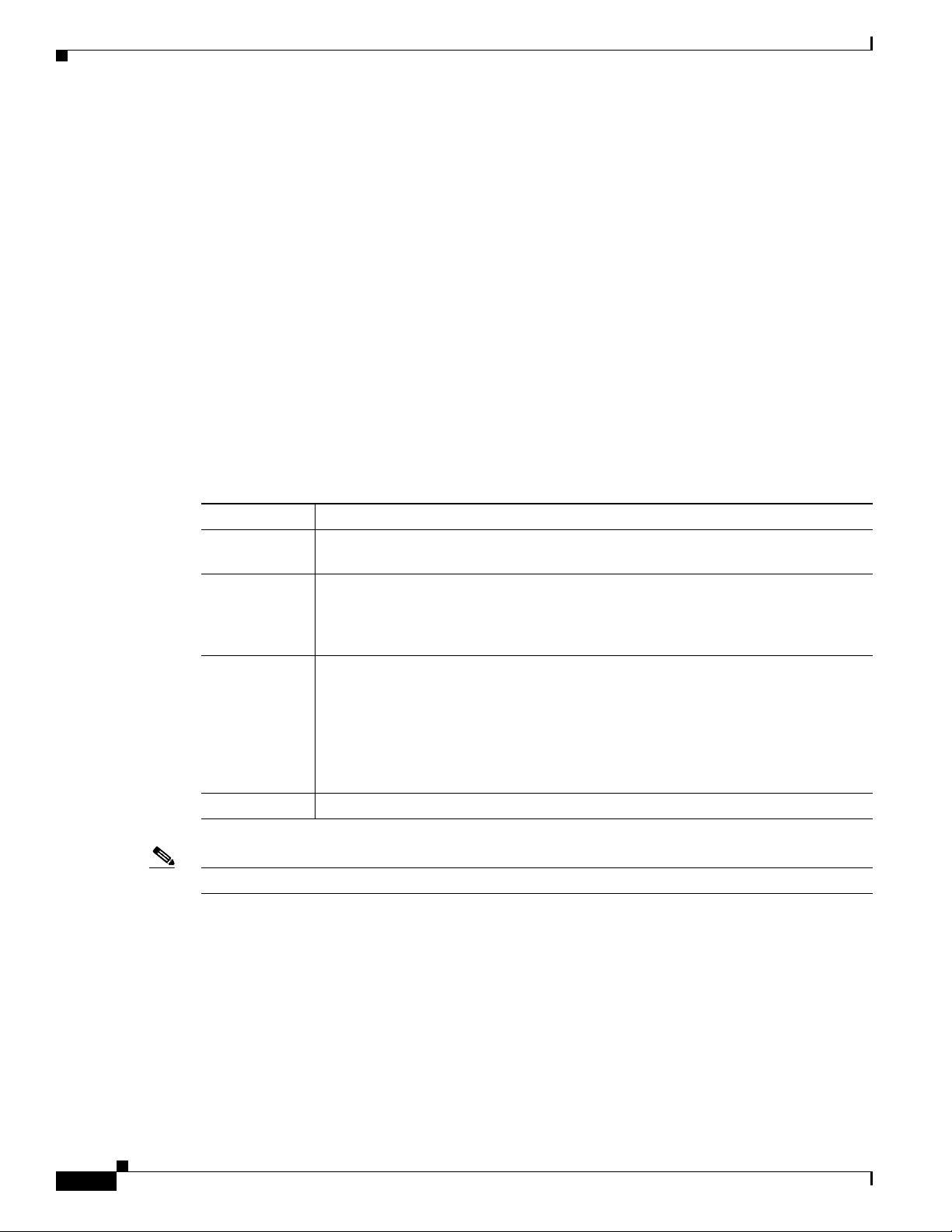
With disk mirroring (used in RAID 1 and RAID 10), data written to one drive is simultaneously written
to another drive. The primary advantage of disk mirroring is that it provides 100 percent data
redundancy. Because the contents of the disk are completely written to a second disk, data is not lost if
one disk fails. In addition, both drives contain the same data at all times, so either disk can act as the
operational disk. If one disk fails, the contents of the other disk can be used to run the system and
reconstruct the failed disk.
Disk mirroring provides 100 percent redundancy but is expensive because each drive in the system must
be duplicated (see Figure 1-2).
1-2
Cisco UCS Servers RAID Guide
OL-26591-01
Page 9
Chapter 1 RAID Overview
Segment 1
Segment 2
Segment 3
Segment 1 Duplicated
Segment 2 Duplicated
Segment 3 Duplicated
Segment 4 Segment 4 Duplicated
Parity
Information About RAID
Figure 1-2 Example of Disk Mirroring (RAID 1)
Parity generates a set of redundancy data from two or more parent data sets. The redundancy data can
be used to reconstruct one of the parent data sets in the event of a drive failure. Parity data does not fully
duplicate the parent data sets, but parity generation can slow the write process. In RAID, this method is
applied to entire drives or stripes across all of the drives in a drive group. There are two types of parity:
• Dedicated parity—The parity data on two or more drives is stored on an additional disk.
Note Parity is distributed across all drives in the drive group.
Disk Spanning
• Distributed parity—The parity data is distributed across more than one drive in the system.
RAID 5 combines distributed parity with disk striping (see Figure 1-3). If a single drive fails, it can be
rebuilt from the parity and the data on the remaining drives. RAID 5 uses parity to provide redundancy
for one drive failure without duplicating the contents of entire drives. RAID 6 uses distributed parity and
disk striping also but adds a second set of parity data so that it can survive up to two drive failures.
Figure 1-3 Example of Distributed Parity (RAID 5)
Segment 1
Segment 7
Segment 13
Segment 19
Segment 25
Parity (26–30)
Segment 2
Segment 8
Segment 14
Segment 20
Parity (21–25)
Segment 26
Segment 3
Segment 9
Segment 15
Parity (16–20)
Segment 21
Segment 4
Segment 10
Parity (11–15)
Segment 16
Segment 22
Segment 28
Segment 5
Parity (6–10)
Segment 11
Segment 17
Segment 23
92 tnemgeS72 tnemgeS
Parity (1–5)
Segment 6
Segment 12
Segment 18
Segment 24
Segment 30
332086
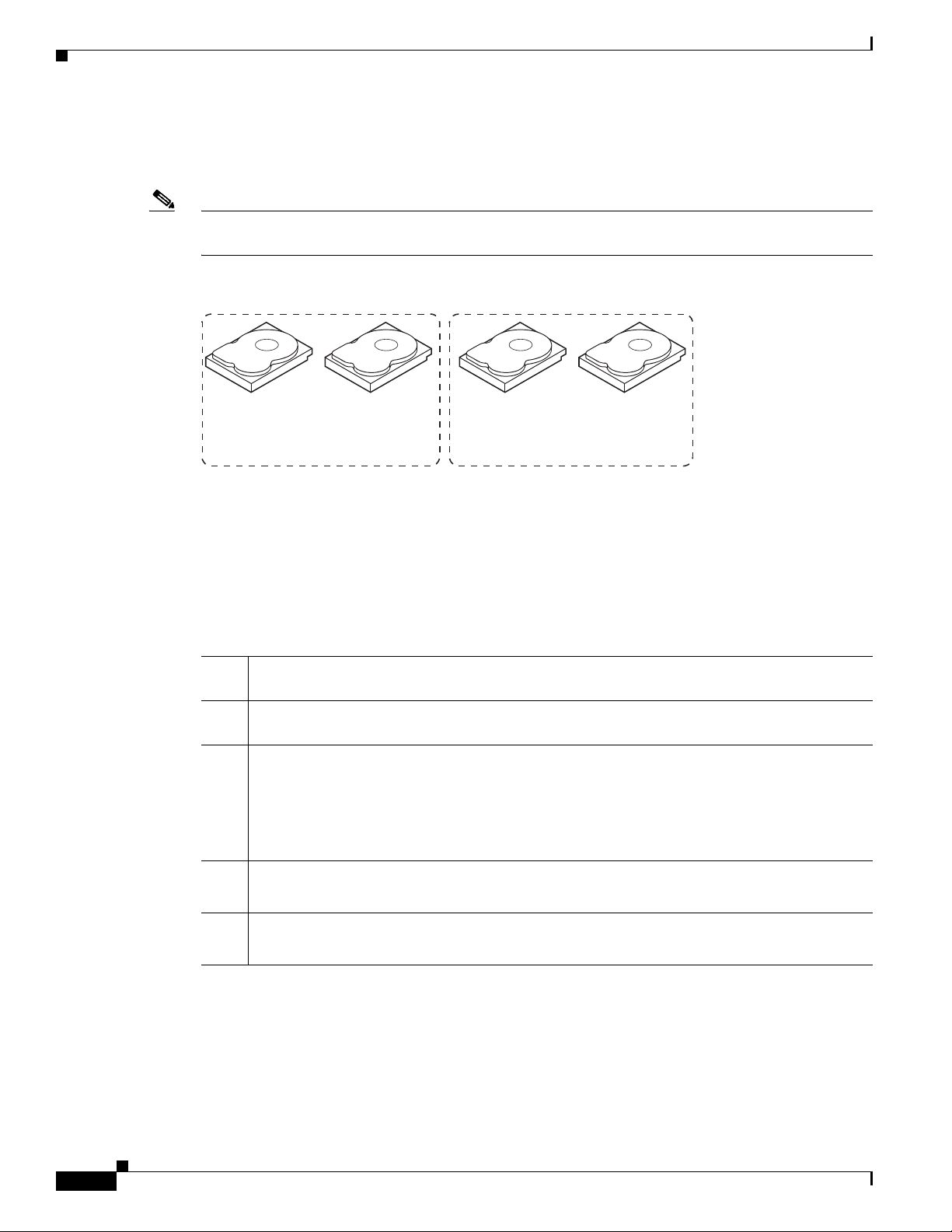
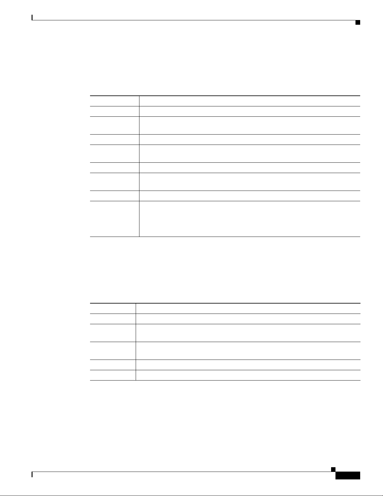
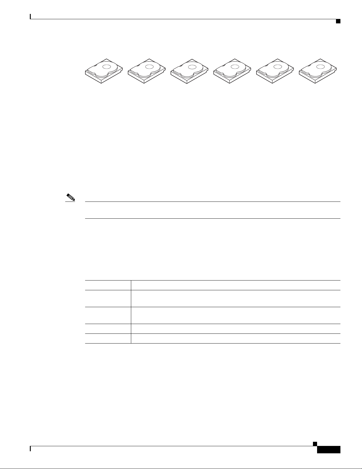
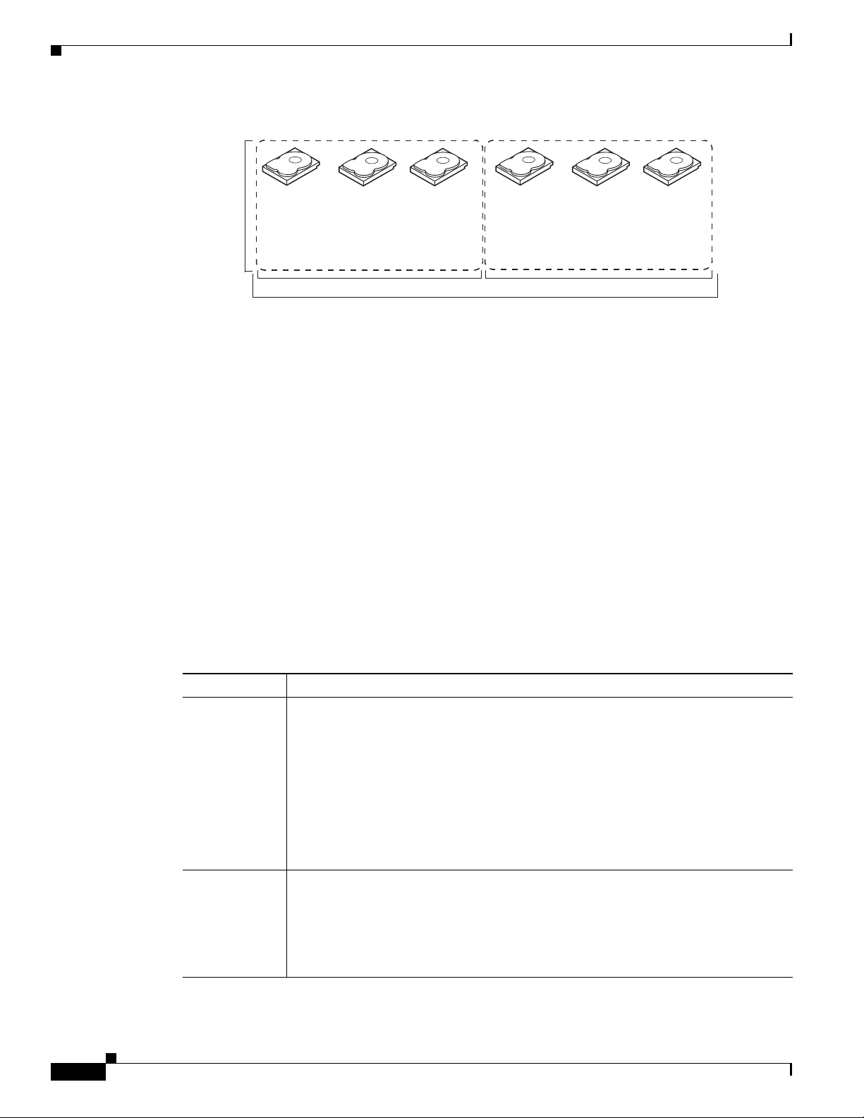
Disk spanning allows multiple drives to function like one big drive. Spanning overcomes lack of disk
space and simplifies storage management by combining existing resources or adding relatively
inexpensive resources. For example, four 20-GB drives can be combined to appear to the operating
system as a single 80-GB drive.
OL-26591-01
Cisco UCS Servers RAID Guide
1-3
Page 10
Information About RAID
60 GB 60 GB
Can be accessed as
one 120-GB drive
60 GB 60 GB
Can be accessed as
one 120-GB drive
332087
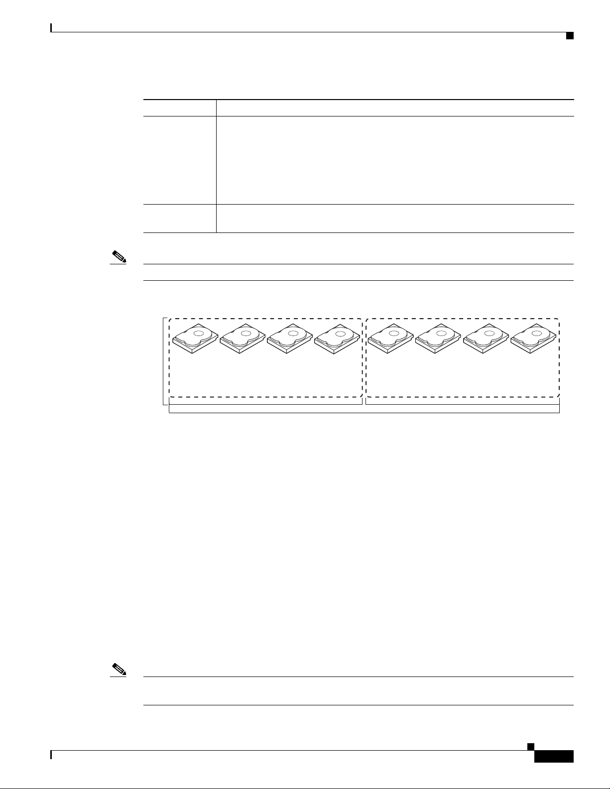
Note Make sure that the spans are in different backplanes, so that if one span fails, you do not lose the whole
Chapter 1 RAID Overview
Spanning alone does not provide reliability or performance enhancements. Spanned virtual drives must
have the same stripe size and must be contiguous. In Figure 1-4, RAID 1 drive groups are turned into a
RAID 10 drive group.
drive group.
Figure 1-4 Example of Disk Spanning
Spanning two contiguous RAID 0 virtual drives does not produce a new RAID level or add fault
tolerance. It does increase the capacity of the virtual drive and improves performance by doubling the
number of physical disks.
Table 1 -1 describes how to configure RAID 00, RAID 10, RAID 50, and RAID 60 by spanning. The
virtual drives must have the same stripe size and the maximum number of spans is eight. The full drive
capacity is used when you span virtual drives; you cannot specify a smaller drive capacity.
Table 1-1 Spanning for RAID 00, RAID 10, RAID 50, and RAID 60
RAID
Level Description
00 Configure RAID 00 by spanning two contiguous RAID 0 virtual drives, up to the maximum
number of supported devices for the controller.
10 Configure RAID 10 by spanning two contiguous RAID 1 virtual drives, up to the maximum
number of supported devices for the controller.
RAID 10 supports a maximum of eight spans. You must use an even number of drives in each
RAID virtual drive in the span.
The RAID 1 virtual drives must have the same stripe size.
50 Configure RAID 50 by spanning two contiguous RAID 5 virtual drives.
The RAID 5 virtual drives must have the same stripe size.
60 Configure RAID 60 by spanning two contiguous RAID 6 virtual drives.
The RAID 6 virtual drives must have the same stripe size.
Hot Spares
1-4
Cisco UCS Servers RAID Guide
A hot spare is an extra, unused drive that is part of the disk subsystem. It is usually in standby mode,
ready for service if a drive fails. If a drive used in a RAID virtual drive fails, a hot spare automatically
takes its place and the data on the failed drive is rebuilt on the hot spare. Hot spares can be used for RAID
levels 1, 5, 6, 10, 50, and 60.
OL-26591-01
Page 11
Chapter 1 RAID Overview
Note When running RAID 0 and RAID 5 virtual drives on the same set of drives (a sliced configuration), a
Information About RAID
Hot spares permit you to replace failed drives without system shutdown or user intervention. MegaRAID
SAS RAID controllers can implement automatic and transparent rebuilds of failed drives using hot spare
drives, providing a high degree of fault tolerance and zero downtime.
rebuild to a hot spare cannot occur after a drive failure until the RAID 0 virtual drive is deleted.
The LSI RAID management software allows you to specify drives as hot spares. When a hot spare is
needed, the RAID controller assigns the hot spare that has a capacity closest to and at least as great as
that of the failed drive to take the place of the failed drive. The failed drive is removed from the virtual
drive and marked ready awaiting removal once the rebuild to a hot spare begins. You can make hot spares
of the drives that are not in a RAID virtual drive.
You can use the RAID management software to designate the hot spare to have enclosure affinity, which
means that if drive failures are present on a split backplane configuration, the hot spare is used first on
the backplane side that it resides in.
If the hot spare is designated as having enclosure affinity, it attempts to rebuild any failed drives on the
backplane that it resides in before rebuilding any other drives on other backplanes.
Note If a rebuild to a hot spare fails for any reason, the hot spare drive is marked as failed. If the source drive
fails, both the source drive and the hot spare drive is marked as failed.
There are two types of hot spares:
• Global hot spare
• Dedicated hot spare
Global Hot Spare
A global hot spare drive can be used to replace any failed drive in a redundant drive group as long as its
capacity is equal to or larger than the capacity of the failed drive. A global hot spare defined on any
channel should be available to replace a failed drive on both channels.
Dedicated Hot Spare
A dedicated hot spare can be used to replace a failed drive only in a chosen drive group. One or more
drives can be designated as a member of a spare drive pool. The most suitable drive from the pool is
chosen for failover. A dedicated hot spare is used before one from the global hot spare pool.
Hot spare drives can be located on any RAID channel. Standby hot spares (not being used in RAID drive
group) are polled every 60 seconds at a minimum, and their status is made available in the drive group
management software. RAID controllers offer the ability to rebuild with a disk that is in a system, but
not initially set to be a hot spare.
When using hot spares, observe the following guidelines:
OL-26591-01
• Hot spares are used only in drive groups with redundancy, which includes RAID levels 1, 5, 6, 10,
50, and 60.
• A hot spare connected to a specific RAID controller can be used to rebuild a drive that is connected
to the same controller only.
Cisco UCS Servers RAID Guide
1-5
Page 12
Information About RAID
Disk Rebuilds
Chapter 1 RAID Overview
• You must assign the hot spare to one or more drives through the controller BIOS or use drive group
management software to place it in the hot spare pool.
• A hot spare must have free space equal to or greater than the drive it replaces. For example, to
replace an 18-GB drive, the hot spare must be 18 GB or larger.
When a drive in a RAID drive group fails, you can rebuild the drive by recreating the data that was stored
on the drive before it failed. The RAID controller recreates the data using the data stored on the other
drives in the drive group. Rebuilding can be done only in drive groups with data redundancy, which
includes RAID 1, 5, 6, 10, 50, and 60 drive groups.
The RAID controller uses hot spares to rebuild failed drives automatically and transparently, at
user-defined rebuild rates. If a hot spare is available, the rebuild can start automatically when a drive
fails. If a hot spare is not available, the failed drive must be replaced with a new drive so that the data on
the failed drive can be rebuilt.
The failed drive is removed from the virtual drive and marked ready awaiting removal when the rebuild
to a hot spare begins. If the system goes down during a rebuild, the RAID controller automatically
restarts the rebuild after the system reboots.
Hot Swap
Note When the rebuild to a hot spare begins, the failed drive is often removed from the virtual drive before
management applications detect the failed drive. When this situation occurs, the events logs show the
drive rebuilding to the hot spare without showing the failed drive. The formerly failed drive is marked
as ready after a rebuild begins to a hot spare.
Note If a source drive fails during a rebuild to a hot spare, the rebuild fails, and the failed source drive is
marked as offline. In addition, the rebuilding hot spare drive is changed back to a hot spare. After a
rebuild fails because of a source drive failure, the dedicated hot spare is still dedicated and assigned to
the correct drive group, and the global hot spare is still global.
An automatic drive rebuild does not start if you replace a drive during a RAID-level migration. The
rebuild must be started manually after the expansion or migration procedure is complete. (RAID-level
migration changes a virtual drive from one RAID level to another.)
A hot swap is the manual replacement of a defective drive unit while the computer is still running
(performing its normal functions). When a new drive is installed, a rebuild occurs automatically if one
of the following happens:
• The newly inserted drive is the same capacity as or larger than the failed drive.
• It is placed in the same drive bay as the failed drive it is replacing.
The RAID controller can be configured to detect the new drives and rebuild the contents of the drive
automatically. The backplane and enclosure must support hot swap for the functionality to work.
1-6
Cisco UCS Servers RAID Guide
OL-26591-01
Page 13
Chapter 1 RAID Overview
Drive States
Information About RAID
A drive state is a property that indicates the status of the drive. Table 1-2 describes the drive states.
Table 1-2 Drive States
State Description
Online A drive that can be accessed by the RAID controller and is part of the virtual drive.
Unconfigured
Good
Hot Spare A drive that is powered up and ready for use as a spare in case an online drive fails.
Failed A drive that was originally configured as Online or Hot Spare but on which the
Rebuild A drive to which data is being written to restore full redundancy for a virtual drive.
Unconfigured
Bad
Missing A drive that was Online but which has been removed from its location.
Offline A drive that is part of a virtual drive but which has invalid data as far as the RAID
A drive that is functioning normally but is not configured as a part of a virtual drive
or as a hot spare.
firmware detects an unrecoverable error.
A drive on which the firmware detects an unrecoverable error; the drive was
Unconfigured Good or the drive could not be initialized.
configuration is concerned.
When a virtual drive with cached data goes offline, the cache for the virtual drive is
discarded. Because the virtual drive is offline, the cache cannot be saved.
Virtual Drive States
A virtual drive state is a property indicating the status of the virtual drive. Tabl e 1-3 describes the virtual
drive states.
Table 1-3 Virtual Drive States
State Description
Optimal The virtual drive operating condition is good. All configured drives are online.
Degraded The virtual drive operating condition is not optimal. One of the configured drives has
Partial
Degraded
Failed The virtual drive has failed.
Offline The virtual drive is not available to the RAID controller.
failed or is offline.
The operating condition in a RAID 6 virtual drive is not optimal. One of the
configured drives has failed or is offline. RAID 6 can tolerate up to two drive failures.
OL-26591-01
Cisco UCS Servers RAID Guide
1-7
Page 14

RAID Levels
RAID Levels
The MegaRAID controller supports RAID levels 0, 00, 1, 5, 6, 10, 50, and 60. It also supports
independent drives (configured as RAID 0 and RAID 00.) The supported RAID levels are summarized
in the following section.
RAID Levels Summary
• RAID 0 uses striping to provide high data throughput, especially for large files in an environment
that does not require fault tolerance.
• RAID 1 uses mirroring so that data written to one drive is simultaneously written to another drive
which is good for small databases or other applications that require small capacity, but complete data
redundancy.
• RAID 5 uses disk striping and parity data across all drives (distributed parity) to provide high data
throughput, especially for small random access.
• RAID 6 uses distributed parity, with two independent parity blocks per stripe, and disk striping. A
RAID 6 virtual drive can survive the loss of two drives without losing data. A RAID 6 drive group,
which requires a minimum of three drives, is similar to a RAID 5 drive group. Blocks of data and
parity information are written across all drives. The parity information is used to recover the data if
one or two drives fail in the drive group.
• A RAID 00 drive group is a spanned drive group that creates a striped set from a series of RAID 0
drive groups.
• RAID 10, a combination of RAID 0 and RAID 1, consists of striped data across mirrored spans. A
RAID 10 drive group is a spanned drive group that creates a striped set from a series of mirrored
drives. RAID 10 allows a maximum of eight spans. You must use an even number of drives in each
RAID virtual drive in the span. The RAID 1 virtual drives must have the same stripe size. RAID 10
provides high data throughput and complete data redundancy but uses a larger number of spans.
Chapter 1 RAID Overview
1-8
• RAID 50, a combination of RAID 0 and RAID 5, uses distributed parity and disk striping. A
RAID 50 drive group is a spanned drive group in which data is striped across multiple RAID 5 drive
groups. RAID 50 works best with data that requires high reliability, high request rates, high data
transfers, and medium-to-large capacity.
Note You cannot have virtual drives of different RAID levels, such as RAID 0 and RAID 5, in the same drive
group. For example, if an existing RAID 5 virtual drive is created out of partial space in an array, the
next virtual drive in the array has to be RAID 5 only.
• RAID 60, a combination of RAID 0 and RAID 6, uses distributed parity, with two independent
parity blocks per stripe in each RAID set, and disk striping. A RAID 60 virtual drive can survive the
loss of two drives in each of the RAID 6 sets without losing data. It works best with data that
requires high reliability, high request rates, high data transfers, and medium-to-large capacity.
Cisco UCS Servers RAID Guide
OL-26591-01
Page 15
Chapter 1 RAID Overview
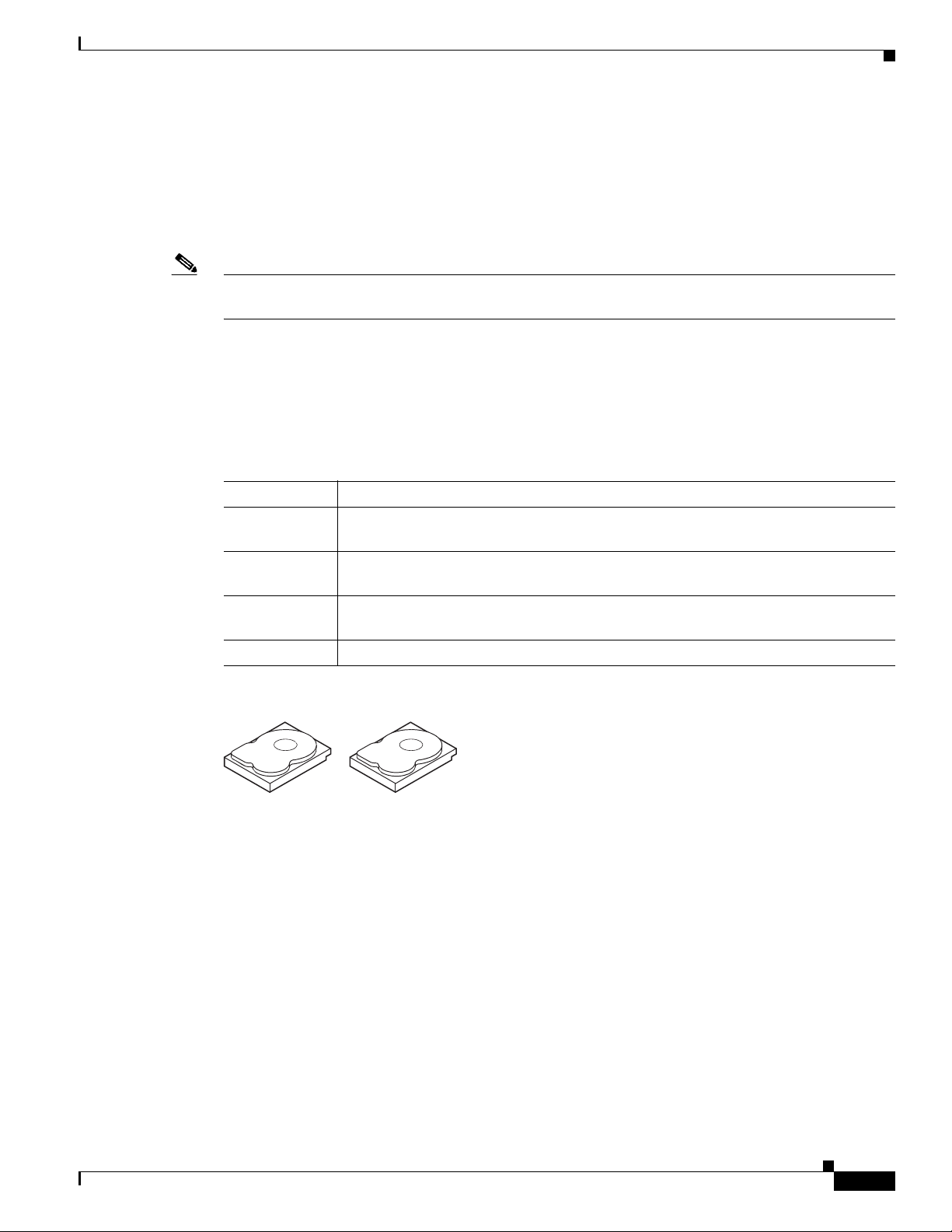
RAID 0
Note RAID level 0 is not fault tolerant. If a drive in a RAID 0 drive group fails, the whole virtual drive (all
RAID Levels
RAID 0 provides disk striping across all drives in the RAID drive group. RAID 0 does not provide any
data redundancy but does offer the best performance of any RAID level. RAID 0 breaks up data into
smaller segments and stripes the data segments across each drive in the drive group. The size of each
data segment is determined by the stripe size. RAID 0 offers high bandwidth.
drives associated with the virtual drive) will fail.
By breaking up a large file into smaller segments, the RAID controller can use both SAS drives and
SATA drives to read or write the file faster. RAID 0 involves no parity calculations to complicate the
write operation, which makes RAID 0 ideal for applications that require high bandwidth, but do not
require fault tolerance. Tab le 1-4 provides an overview of RAID 0. Figure 1-5 shows an example of a
RAID 0 drive group advantage.
Table 1-4 RAID 0 Overview
Feature Description
Uses Provides high data throughput, especially for large files. Any environment that does
not require fault tolerance.
Benefits Provides increased data throughput for large files.
No capacity loss penalty for parity.
Limitations Does not provide fault tolerance or high bandwidth.
All data is lost if any drive fails.
Drives 1 to 32.
Figure 1-5 RAID 0 Drive Group Example
Segment 1
Segment 3
Segment 5
Segment 7 Segment 8
Segment 2
Segment 4
Segment 6
332088
OL-26591-01
Cisco UCS Servers RAID Guide
1-9
Page 16
RAID Levels
RAID 1
Chapter 1 RAID Overview
In RAID 1, the RAID controller duplicates all data from one drive to a second drive in the drive group.
RAID 1 supports an even number of drives from 2 to 32 in a single span. RAID 1 provides complete data
redundancy but at the cost of doubling the required data storage capacity. Tab le 1- 5 provides an overview
of RAID 1. Figure 1-6 shows an example of a RAID 1 drive group.
Table 1-5 RAID 1 Overview
Feature Description
Uses Use RAID 1 for small databases or any other environment that requires fault
tolerance, but small capacity.
Benefits Provides complete data redundancy. RAID 1 is ideal for any application that requires
fault tolerance and minimal capacity.
Limitations Requires twice as many drives. Performance is impaired during drive rebuilds.
Drives 2 to 32 (must be an even number of drives).
RAID 5
Figure 1-6 RAID 1 Drive Group Example
Segment 1
Segment 5
...
RAID1
Segment 1
Duplicate
Segment 5
Duplicate
Segment 2
Segment 6
...
RAID1
Segment 2
Duplicate
Segment 6
Duplicate
Segment 3
Segment 7
...
RAID1
Segment 3
Duplicate
Segment 7
Duplicate
Segment 4
Segment 8
...
Segment 4
Duplicate
Segment 8
Duplicate
RAID1
332089
RAID 5 includes disk striping at the block level and parity. Parity is the property of the data of being odd
or even, and parity checking is used to detect errors in the data. In RAID 5, the parity information is
written to all drives. RAID 5 is best suited for networks that perform a lot of small input/output (I/O)
transactions simultaneously. RAID 5 provides data redundancy, high read rates, and good performance
in most environments. It also provides redundancy with the lowest loss of capacity.
In addition, RAID 5 is good for any application that has high read request rates but has low write request
rates.
RAID 5 addresses the congestion issue for random I/O operations. Because each drive contains both data
and parity, numerous writes can take place concurrently.
Table 1 -6 provides an overview of RAID 5. Figure 1-7 shows an example of a RAID 5 drive group.
1-10
Cisco UCS Servers RAID Guide
OL-26591-01
Page 17
Chapter 1 RAID Overview
Segment 1
Segment 7
Segment 2
Segment 8
Segment 3
Segment 9
Segment 4
Segment 10
Segment 5
Parity (6–10)
Parity (11–15)
Parity (1–5)
Segment 6
Segment 12
Segment 15
Segment 11
Segment 14
Segment 13
Segment 19
Segment 25
Segment 20
Segment 23
Segment 18
Segment 21
Segment 16
Segment 22
Segment 17
Parity (21–25)
Parity (26–30)
Parity (16–20)
Segment 24
Segment 30
92 tnemgeS72 tnemgeS
Segment 26
Segment 28
332090
RAID Levels
Table 1-6 RAID 5 Overview
Features Description
Uses Provides high data throughput, especially for large files. Use RAID 5 for transaction
processing applications because each drive can read and write independently. If a
drive fails, the RAID controller uses the parity drive to recreate all missing
information. Use also for office automation and online customer service that requires
fault tolerance. Use for any application that has high read request rates but low write
request rates.
Benefits Provides data redundancy, high read rates, and good performance in most
environments. RAID 5 provides redundancy with the lowest loss of capacity.
Limitations Not well-suited to tasks that require a large number of writes. RAID 5 has problems
if no cache is used (clustering). The drive’s performance is reduced if a drive is being
rebuilt. Environments with few processes do not perform as well because the RAID
overhead is not offset by the performance gains in handling simultaneous processes.
Drives 3 to 32.
Note Parity is distributed across all drives in the drive group.
Figure 1-7 RAID 5 Drive Group Example
OL-26591-01
Cisco UCS Servers RAID Guide
1-11
Page 18
RAID Levels
RAID 6
Chapter 1 RAID Overview
RAID 6 is similar to RAID 5 (disk striping and distributed parity), except that instead of one parity block
per stripe, there are two. With two independent parity blocks, RAID 6 can survive the loss of two drives
in a virtual drive without losing data. RAID 6 provides a high level of data protection through the use of
a second parity block in each stripe. Use RAID 6 for data that requires a very high level of protection
from loss.
RAID 6 is best suited for networks that perform a lot of small input/output (I/O) transactions
simultaneously. It provides data redundancy, high read rates, and good performance in most
environments.
In the case of a failure of one drive or two drives in a virtual drive, the RAID controller uses the parity
blocks to recreate all of the missing information. If two drives in a RAID 6 virtual drive fail, two drive
rebuilds are required, one for each drive. These rebuilds do not occur at the same time. The controller
rebuilds one failed drive and then the other failed drive.
Table 1 -7 provides an overview of a RAID 6 drive group. Figure 1-8 shows a RAID 6 data layout. The
second set of parity drives are denoted by Q. The P drives follow the RAID 5 parity scheme.
Table 1-7 RAID 6 Overview
Features Description
Uses Use for office automation and online customer service that requires fault tolerance.
Use for any application that has high read request rates but low write request rates.
Benefits Provides data redundancy, high read rates, and good performance in most
environments, can survive the loss of two drives or the loss of a drive while another
drive is being rebuilt, and provides the highest level of protection against drive
failures of all of the RAID levels. The read performance is similar to that of RAID 5.
Limitations Not well-suited to tasks that require a large number of writes. A RAID 6 virtual drive
has to generate two sets of parity data for each write operation, which results in a
significant decrease in performance during writes. The drive performance is reduced
during a drive rebuild. Environments with few processes do not perform as well,
because the RAID overhead is not offset by the performance gains in handling
simultaneous processes. RAID 6 costs more because of the extra capacity required
by using two parity blocks per stripe.
Drives 3 to 32.
Note Parity is distributed across all drives in the drive group.
1-12
Cisco UCS Servers RAID Guide
OL-26591-01
Page 19
Chapter 1 RAID Overview
Segment 1
Segment 6
Segment 2
Segment 7
Segment 3
Segment 8
Segment 4
Parity (P5–P8)
Parity (P1–P4)
Parity (Q5–Q8)
Parity (Q9–Q12)
Parity (Q1–Q4)
Segment 5
Segment 10
Parity (P9–P12)
Segment 9
Segment 12
Segment 11
Segment 16
Parity (P17–P20)
Parity (P13–P16)
Segment 19
Segment 15
Segment 17
Segment 13
Segment 18
Segment 14
Parity (Q17–Q20)
Parity (Q13–Q16)
Segment 20
332094
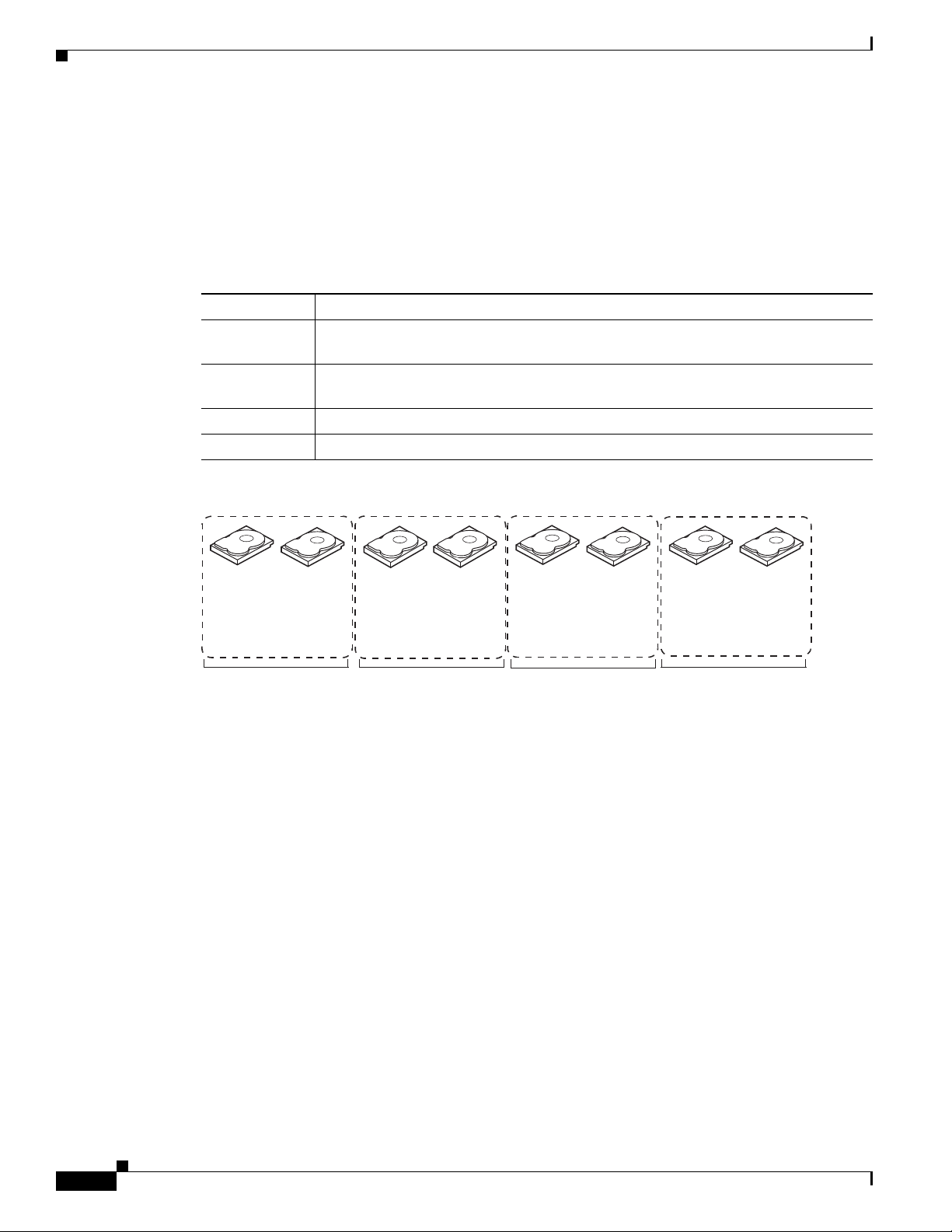
RAID 00
RAID Levels
Figure 1-8 RAID 6 Drive Group Example
A RAID 00 drive group is a spanned drive group that creates a striped set from a series of RAID 0 drive
groups. RAID 00 does not provide any data redundancy, but along with RAID 0, RAID 00 offers the best
performance of any RAID level. RAID 00 breaks up data into smaller segments and stripes the data
segments across each drive in the drive groups. The size of each data segment is determined by the stripe
size. RAID 00 offers high bandwidth.
Note RAID level 00 is not fault tolerant. If a drive in a RAID 0 drive group fails, the whole virtual drive (all
drives associated with the virtual drive) fails.
By breaking up a large file into smaller segments, the RAID controller can use both SAS drives and
SATA drives to read or write the file faster. RAID 00 involves no parity calculations to complicate the
write operation, which makes RAID 00 ideal for applications that require high bandwidth but do not
require fault tolerance. Tab le 1-8 provides an overview of RAID 00. Figure 1-9 shows an example of a
RAID 00 drive group.
Table 1-8 RAID 00 Overview
Features Description
Uses Provides high data throughput, especially for large files. Use RAID 00 in any
environment that does not require fault tolerance.
Benefits Provides increased data throughput for large files. RAID 00 has no capacity loss
penalty for parity.
Limitations Does not provide fault tolerance or high bandwidth. All data is lost if any drive fails.
Drives Two to the maximum number of drives that are supported by the controller.
OL-26591-01
Cisco UCS Servers RAID Guide
1-13
Page 20
RAID Levels
Segment 1
Segment 2Segment
3
Segment 6
Segment
8
Segment
5
Segment 7
Segment
9
Segment
11
Segment
13
Segment 15
Segment
10
Segment
12
Segment
14
Segment
16
Segment
4
...
...
...
...
RAID
0
RAID
0
RAID
0
RAID
0
RAID
00
RAID 0
Segment
17
Segment
18
Segment
19
Segment 20Segment
21
Segment
22
Segment
23
Segment
24
RAID 10
Chapter 1 RAID Overview
Figure 1-9 RAID 00 Drive Group Example Using Two Drives
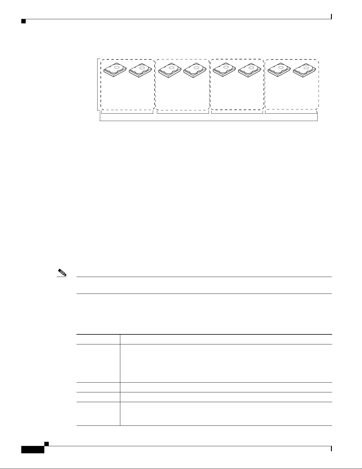
RAID 10 is a combination of RAID 0 and RAID 1 and consists of stripes across mirrored drives.
RAID 10 breaks up data into smaller blocks and mirrors the blocks of data to each RAID 1 drive group.
The first RAID 1 drive in each drive group then duplicates its data to the second drive. The size of each
block is determined by the stripe size parameter, which is set during the creation of the RAID set. The
RAID 1 virtual drives must have the same stripe size.
1-14
Spanning is used because one virtual drive is defined across more than one drive group. Virtual drives
defined across multiple RAID 1 level drive groups are referred to as RAID level 10, (1+0). Data is striped
across drive groups to increase performance by enabling access to multiple drive groups simultaneously.
Each spanned RAID 10 virtual drive can tolerate multiple drive failures, as long as each failure is in a
separate drive group. If there are drive failures, less than the total drive capacity is available.
Configure RAID 10 by spanning two contiguous RAID 1 virtual drives, up to the maximum number of
supported devices for the controller. RAID 10 supports a maximum of eight spans with a maximum of
32 drives per span. You must use an even number of drives in each RAID 10 virtual drive in the span.
Note Other factors, such as the type of controller, can restrict the number of drives supported by RAID 10
virtual drives.
Table 1 -9 provides an overview of RAID 10. In Figure 1-10, virtual drive 0 is created by distributing
data across four RAID 1 drive groups (drive groups 0 through 3).
Table 1-9 RAID 10 Overview
Benefits Description
Uses Appropriate when used with data storage that needs 100 percent redundancy of
mirrored drive groups and that also needs the enhanced I/O performance of RAID 0
(striped drive groups.) RAID 10 works well for medium-sized databases or any
environment that requires a higher degree of fault tolerance and moderate to medium
capacity.
Benefits Provides both high data transfer rates and complete data redundancy.
Limitations Requires twice as many drives as all other RAID levels except RAID 1.
Drives Two to 8 equal spans of RAID 1 drive groups containing 2 to 32 drives each (limited
by the maximum number of devices supported by the controller). You must use an
Cisco UCS Servers RAID Guide
even number of drive spans.
OL-26591-01
Page 21
Chapter 1 RAID Overview
RAID Levels
Figure 1-10 RAID 10 Virtual Drive Example
RAID 50
RAID 10
Segment 1
Segment 5
...
RAID1
Segment 1
Duplicate
Segment 5
Duplicate
Segment 2
Segment 6
...
RAID1
Segment 2
Duplicate
Segment 6
Duplicate
RAID 0
Segment 3
Segment 7
...
RAID1
Segment 3
Duplicate
Segment 7
Duplicate
Segment 4
Segment 8
...
Segment 4
Duplicate
Segment 8
Duplicate
RAID1
RAID 50 provides the features of both RAID 0 and RAID 5. RAID 50 includes both parity and disk
striping across multiple drive groups. RAID 50 is best implemented on two RAID 5 drive groups with
data striped across both drive groups.
RAID 50 breaks up data into smaller blocks and stripes the blocks of data to each RAID 5 disk set.
RAID 5 breaks up data into smaller blocks, calculates parity, and writes the blocks of data and parity to
each drive in the drive group. The size of each block is determined by the stripe size parameter, which
is set during the creation of the RAID set.
RAID level 50 can support up to eight spans and tolerate up to eight drive failures though less than total
drive capacity is available. Though multiple drive failures can be tolerated, only one drive failure can be
tolerated in each RAID 5 level drive group.
Table 1 -10 provides an overview of RAID 50. In Figure 1-11, virtual drive 0 is created by distributing
data across two RAID 5 drive groups.
332143
Table 1-10 RAID 50 Overview
Features Description
Uses Appropriate when used with data that requires high reliability, high request rates,
high data transfer, and medium to large capacity.
Benefits Provides high data throughput, data redundancy, and very good performance.
Limitations Requires 2 to 8 times as many parity drives as RAID 5.
Drives Two to 8 equal spans of RAID 5 drive groups containing 3 to 32 drives each (limited
by the maximum number of devices supported by the controller.)
OL-26591-01
Cisco UCS Servers RAID Guide
1-15
Page 22
RAID Levels
Segment 1
Segment 2
Segment 5
Segment 6
RAID 0
RAID 50
(Segment 1,2)
Segment 3
Segment 4
Segment 8
Segment 7
Segment 9
Segment 10
Segment 11
Segment 12
(Segment 5,6)
(Segment 9,10)
(Segment 11,12)
(Segment 7,8)
(Segment 3,4)
RAID 5 RAID 5
332097
RAID 60
Chapter 1 RAID Overview
Figure 1-11 RAID 50 Virtual Drive Example
RAID 60 provides the features of both RAID 0 and RAID 6 and includes both parity and disk striping
across multiple drive groups. RAID 6 supports two independent parity blocks per stripe. A RAID 60
virtual drive can survive the loss of two drives in each of the RAID 6 sets without losing data. RAID 60
is best implemented on two RAID 6 drive groups with data striped across both drive groups.
RAID 60 breaks up data into smaller blocks and stripes the blocks of data to each RAID 6 disk set.
RAID 6 breaks up data into smaller blocks, calculates parity, and writes the blocks of data and parity to
each drive in the drive group. The size of each block is determined by the stripe size parameter, which
is set during the creation of the RAID set.
RAID 60 can support up to 8 spans and tolerate up to 16 drive failures though less than total drive
capacity is available. Two drive failures can be tolerated in each RAID 6 level drive group.
Table 1 -11 provides an overview of RAID 60. Figure 1-12 shows a RAID 6 data layout. The second set
of parity drives are denoted by Q. The P drives follow the RAID 5 parity scheme.
Table 1-11 RAID 60 Overview
Features Description
Uses Provides a high level of data protection through the use of a second parity block in
each stripe. Use RAID 60 for data that requires a very high level of protection from
loss.
In the case of a failure of one drive or two drives in a RAID set in a virtual drive, the
RAID controller uses the parity blocks to recreate all of the missing information. If
two drives in a RAID 6 set in a RAID 60 virtual drive fail, two drive rebuilds are
required, one for each drive. These rebuilds can occur at the same time.
Use for office automation and online customer service that requires fault tolerance.
Use for any application that has high read request rates but low write request rates.
Benefits Provides data redundancy, high read rates, and good performance in most
environments. Each RAID 6 set can survive the loss of two drives or the loss of a
drive while another drive is being rebuilt. RAID 60 provides the highest level of
protection against drive failures of all of the RAID levels. The read performance is
similar to that of RAID 50, though random reads in RAID 60 might be slightly faster
because data is spread across at least one more disk in each RAID 6 set.
1-16
Cisco UCS Servers RAID Guide
OL-26591-01
Page 23
Chapter 1 RAID Overview
Segment 1
Segment 8
Segment 2
Segment 7
Segment 10
Segment 5
Parity (P1–P2)
Parity (Q11–Q12)
Parity (Q1–Q2)
Segment 11
Segment 12
Parity (P15–P16)
Segment 15
Segment 16
Parity (Q15–Q16)
Segment 3
Segment 6
Segment 4
Parity (P9–P10)
Parity (Q9–Q10)Parity (P11–P12)
Segment 9
Parity (P13–P14)
Segment 14
Segment 13
Parity (Q13–Q14)
RAID 6
RAID 6
RAID 0
Parity (Q3–Q4)
Parity (P3–P4)
Parity (Q5–Q6)
Parity (P5–P6)
Parity (P3–P4)
Parity (Q3–Q4)
RAID
60
Note Parity is distributed across all drives in the drive group.
RAID Levels
Table 1-11 RAID 60 Overview (continued)
Features Description
Limitations Not well suited to tasks using many writes. A RAID 60 virtual drive has to generate
two sets of parity data for each write operation, which results in a significant decrease
in performance during writes. Drive performance is reduced during a drive rebuild.
Environments with few processes do not perform as well because the RAID overhead
is not offset by the performance gains in handling simultaneous processes. RAID 6
costs more because of the extra capacity required by using two parity blocks per
stripe.
Drives Two to 8 equal spans of RAID 6 drive groups containing 3 to 32 drives each (limited
by the maximum number of devices supported by the controller.)
Figure 1-12 RAID 60 Virtual Drive Example
Fault Tolerance
OL-26591-01
Fault tolerance is the capability of the subsystem to undergo a drive failure or failures without
compromising data integrity and processing capability. The RAID controller provides this support
through redundant drive groups in RAID levels 1, 5, 6, 10, 50, and 60. The system can operate properly
even with a drive failure in a drive group, although performance might be degraded to some extent.
• A RAID 1 drive group has two drives and can tolerate one drive failure.
• A RAID 5 drive group can tolerate one drive failure in each RAID 5 drive group.
• A RAID 6 drive group can tolerate up to two drive failures.
• Each spanned RAID 10 virtual drive can tolerate multiple drive failures as long as each failure is in
a separate drive group.
• A RAID 50 virtual drive can tolerate two drive failures as long as each failure is in a separate drive
group.
• RAID 60 drive groups can tolerate up to two drive failures in each drive group.
Note RAID level 0 is not fault tolerant. If a drive in a RAID 0 drive group fails, the whole virtual drive (all
drives associated with the virtual drive) fails.
Cisco UCS Servers RAID Guide
1-17
Page 24
Generic Drive Replacement Procedure
Fault tolerance is often associated with system availability because it allows the system to be available
during the failures. However, it is also important for the system to be available during the repair of the
problem.
Hot spares are important in fault tolerance; see Hot Spares, page 1-4 for more information.
Auto-rebuild allows a failed drive to be replaced and the data automatically rebuilt by hot swapping the
drive in the same drive bay. See Hot Swap, page 1-6 for more information. The RAID drive group
continues to handle requests while the rebuild occurs.
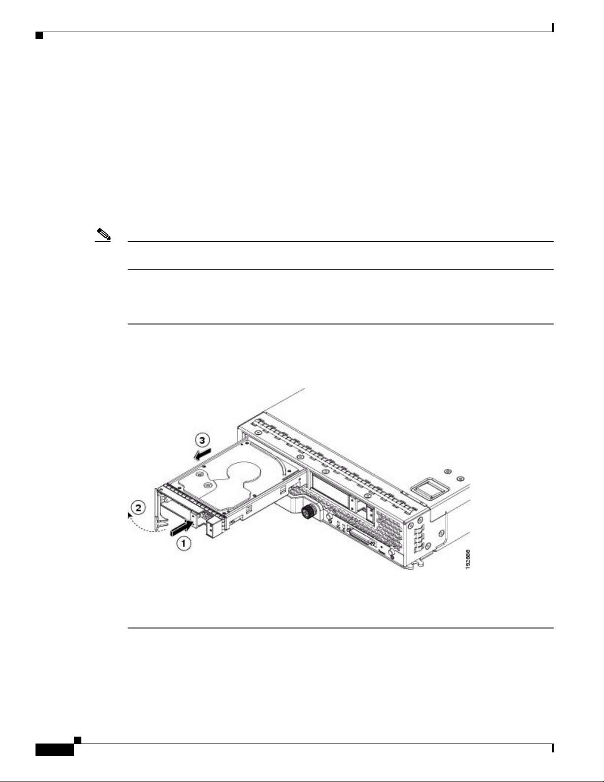
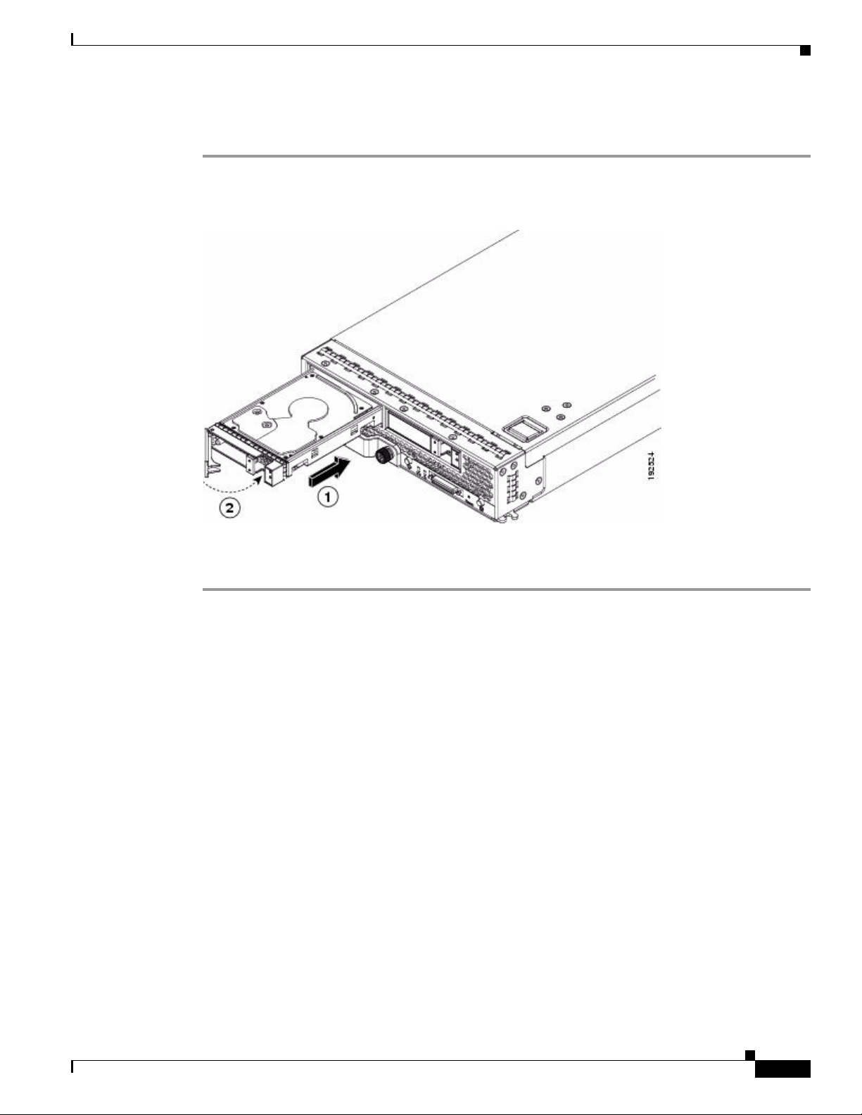
Generic Drive Replacement Procedure
Note B-series blade servers are shown but the mechanical features (release button, eject lever) are the same
for most B-series and C-series servers.
Removing a Drive from a Server
Chapter 1 RAID Overview
Step 1 Push the button to release the ejector, fully extend the ejection lever and then pull the hard drive from its
slot. See Figure 1-13.
Figure 1-13 Removing the Drive
Step 2
Step 3 Install a blank faceplate (N20-BBLKD) to keep dust out of the server if the slot will remain empty.
Place the hard drive on an antistatic mat or antistatic foam if you are not immediately reinstalling it in
another blade server.
1-18
Cisco UCS Servers RAID Guide
OL-26591-01
Page 25
Chapter 1 RAID Overview
Installing a Drive in a Server
Step 1 Place the hard drive lever into the open position by pushing the release button (see Figure 1-14).
Figure 1-14 Installing a Hard Drive in a Blade Server
Platform-Specific RAID and Drive Procedures
Step 2
Step 3 Push the hard drive lever into the closed position.
Gently slide the hard drive into the opening in the blade server until it seats into place.
If you need to move a RAID cluster, see the Moving a RAID Cluster section of the “Troubleshooting
Server Hardware” chapter of the Cisco UCS Troubleshooting Guide.
Platform-Specific RAID and Drive Procedures
B-series RAID and supported drive information that was previously in the software configuration,
hardware installation and service, and troubleshooting guides is repeated in this guide. B series servers
all have onboard RAID controllers that cannot be removed or upgraded. Only software configuration and
drive operations appropriate for that server’s controller are possible.
Supported RAID controllers for all models are listed in RAID Controllers in UCS Servers, page 3-10.
The C-Series hardware installation guides each have a “RAID Considerations” appendix that provides
information about supported RAID controllers and cables, plus cabling instructions specific to each
server model. See that documentation as needed at:
http://www.cisco.com/en/US/products/ps10493/prod_installation_guides_list.html
OL-26591-01
Cisco UCS Servers RAID Guide
1-19
Page 26

Platform-Specific RAID and Drive Procedures
Chapter 1 RAID Overview
1-20
Cisco UCS Servers RAID Guide
OL-26591-01
Page 27

CHA P T ER
2
Using Cisco Integrated Management Controller and Cisco UCS Server Configuration Utility for RAID Monitoring and Configuring
This chapter provides information about monitoring and configuring your RAID controller in your Cisco
Integrated Management Controller (CIMC) and Cisco UCS Server Configuration Utility. The Cisco
C-Series servers have built-in monitoring and configuration tools for storage, including RAID.
This chapter contains the following sections:
• Cisco Integrated Management Controller—Viewing Storage Properties, page 2-1
• Cisco UCS Server Configuration Utility—RAID Configuration, page 2-2
Note The tools and software referred to in this chapter are used only in C-series rack-mounted servers that are
not integrated with Cisco UCS Manager.
Cisco Integrated Management Controller—Viewing Storage Properties
CIMC is the management service for the C-Series servers and runs within the server.
You can use a web-based GUI or Secure Shell-based CLI to access, configure, administer, and monitor
the server. Almost all tasks can be performed in either interface, and the results of tasks performed in
one interface are displayed in another.
The configuration information for CIMC is located in the Cisco UCS C-Series Rack-Mount Servers
Configuration Guide and the Cisco UCS C-Series Rack-Mount Servers CLI Configuration Guide. For
details, see the guide that applies to the release that you are using.
A complete list of GUI and CLI configuration guides can be found here: Cisco UCS C-Series
Configuration Guides.
The following information is included:
• Storage adapters—Including all MegaRAID and Cisco Flexible Flash controllers.
• Controller information—that include the following:
–
PCI information
–
Manufacturing information
Cisco UCS Servers RAID Guide
OL-26591-01
2-1
Page 28

Chapter 2 Using Cisco Integrated Management Controller and Cisco UCS Server Configuration Utility for RAID
Cisco Integrated Management Controller—Viewing Storage Properties
–
Running and startup firmware image information
–
Virtual and physical drive counts
–
General settings
–
Capabilities
–
Hardware configuration
–
Error counters
• Physical drive information—Including general drive information, identification information, and
drive status.
• Virtual drive information—Including general drive information, RAID information, and physical
drive information.
• Battery backup unit information (does not apply to Cisco Flexible Flash).
Cisco UCS Server Configuration Utility—RAID Configuration
You can use the RAID Configuration section in the Cisco UCS Server Configuration Utility document
to configure your system RAID controllers.
RAID levels supported by SCU are RAID 0, 1, 5, and 6.
The latest documentation can be found here: Cisco UCS Server Configuration Utility, Release 3.0 User
Guide.
If your system has multiple RAID controllers, Cisco UCS Server Configuration Utility displays a list of
all available RAID devices. This feature is described in the Server Configuration section.
Three types of RAID configurations can be set up using Cisco UCS Server Configuration Utility. This
feature is documented in the RAID configuration section.
• Automatic setup with redundancy
• Automatic setup without redundancy
• Create custom or multiple RAID arrays
2-2
Cisco UCS Servers RAID Guide
OL-26591-01
Page 29

CHA P T ER
3
Using Cisco UCS Manager for RAID Configuring and Monitoring
This chapter describes monitoring and configuring your RAID controller using Cisco UCS Manager. The
Cisco B-Series servers have built-in monitoring and configuration tools for storage, including RAID.
This chapter contains the following sections:
• Cisco UCS Manager Configuration, page 3-1
• Server Disk Drive Monitoring, page 3-7
• RAID Controllers in UCS Servers, page 3-10
Note Cisco UCS Manager is used both with B-series blade servers and C-series rack servers that have been
integrated.
Cisco UCS Manager Configuration
Cisco UCS Manager interfaces with the LSI controllers and software and creates RAID configurations
as part of creating local disk configuration policies, which allow the same configuration steps to be
applied to many servers at once.
Local Disk Configuration Policy
This policy configures any optional SAS local drives that have been installed on a server through the
onboard RAID controller of the local drive. This policy enables you to set a local disk mode for all
servers that are associated with a service profile that includes the local disk configuration policy.
The local disk modes include the following:
• No Local Storage—For a diskless server or a SAN-only configuration. If you select this option, you
cannot associate any service profile that uses this policy with a server that has a local disk.
• RAID 0 Striped—Data is striped across all disks in the array, providing fast throughput. There is no
data redundancy, and all data is lost if any disk fails.
• RAID 1 Mirrored—Data is written to two disks, which provides complete data redundancy if one
disk fails. The maximum array size is equal to the available space on the smaller of the two drives.
• Any Configuration—For a server configuration that carries forward the local disk configuration
without any changes.
OL-26591-01
Cisco UCS Servers RAID Guide
3-1
Page 30

Cisco UCS Manager Configuration
• No RAID—For a server configuration that removes the RAID and leaves the disk MBR and payload
unaltered.
• RAID 5 Striped Parity—Data is striped across all disks in the array. Part of the capacity of each disk
stores parity information that can be used to reconstruct data if a disk fails. RAID 5 provides good
data throughput for applications with high read request rates.
• RAID 6 Striped Dual Parity—Data is striped across all disks in the array, and two parity disks are
used to provide protection against the failure of up to two physical disks. In each row of data blocks,
two sets of parity data are stored.
• RAID10 Mirrored and Striped— RAID 10 uses mirrored pairs of disks to provide complete data
redundancy and high throughput rates.
You must include this policy in a service profile, and that service profile must be associated with a server
for the policy to take effect.
Guidelines for all Local Disk Configuration Policies
Before you create a local disk configuration policy, consider the following guidelines:
• No Mixed HDDs and SSDs
Mixing HDD and SSDs in a single server or RAID configuration is not supported.
Chapter 3 Using Cisco UCS Manager for RAID Configuring and Monitoring
• Do Not Assign a Service Profile with the Default Local Disk Configuration Policy from a B200 M1
or M2 to a B200 M3
Due to the differences in the RAID/JBOD support provided by the storage controllers of B200 M1
and M2 servers and those of the B200 M3 server, you cannot assign or reassign a service profile that
includes the default local disk configuration policy from a B200M1 or M2 server to a B200 M3
server. The default local disk configuration policy includes the Any Configuration or JBOD modes.
• Impact of Upgrade to Release 1.3(1i) or Higher
An upgrade from an earlier Cisco UCS firmware release to release 1.3(1i) or higher has the
following impact on the Protect Configuration property of the local disk configuration policy the
first time servers are associated with service profiles after the upgrade:
• Unassociated Servers
After you upgrade the Cisco UCS domain, the initial server association proceeds without
configuration errors whether or not the local disk configuration policy matches the server hardware.
Even if you enable the Protect Configuration property, Cisco UCS does not protect the user data on
the server if there are configuration mismatches between the local disk configuration policy on the
previous service profile and the policy in the new service profile.
Note If you enable the Protect Configuration property and the local disk configuration policy
encounters mismatches between the previous service profile and the new service profile, all
subsequent service profile associations with the server are blocked.
• Associated Servers
3-2
Any servers that are already associated with service profiles do not reboot after the upgrade. Cisco
UCS Manager does not report any configuration errors if there is a mismatch between the local disk
configuration policy and the server hardware.
Cisco UCS Servers RAID Guide
OL-26591-01
Page 31

Chapter 3 Using Cisco UCS Manager for RAID Configuring and Monitoring
When a service profile is disassociated from a server and a new service profile associated, the setting
for the Protect Configuration property in the new service profile takes precedence and overwrites
the setting in the previous service profile.
Guidelines for Local Disk Configuration Policies Configured for RAID
• No Mixed HDDs and SSDs
Do not include HDDs and SSDs in a single RAID configuration.
• Server May Not Boot After RAID 1 Cluster Migration if Any Configuration Mode Specified in
Service Profile
After RAID 1 clusters are migrated, you must associate a service profile with the server. If the local
disk configuration policy in the service profile is configured with Any Configuration mode rather
than RAID 1, the RAID LUN remains in an “inactive” state during and after association. As a result,
the server cannot boot.
To avoid this issue, ensure that the service profile you associate with the server contains the identical
local disk configuration policy as the original service profile before the migration and does not
include the Any Configuration mode.
• Configure RAID Settings in Local Disk Configuration Policy for Servers with MegaRAID Storage
Controllers
If a blade server or integrated rack-mount server has a MegaRAID controller, you must configure
RAID settings for the drives in the Local Disk Configuration policy included in the service profile
for that server.
Cisco UCS Manager Configuration
If you do not configure your RAID LUNs before installing the OS, disk discovery failures might
occur during the installation and you might see error messages such as “No Device Found.”
• Do Not Use JBOD Mode on Servers with MegaRAID Storage Controllers
Do not configure or use JBOD mode or JBOD operations on any blade server or integrated
rack-mount server with MegaRAID storage controllers. JBOD mode and operations are not
supported on these servers.
• Maximum of One RAID Volume Using RAID 0 or RAID 1 Disk Policy
A rack-mount server that has been integrated with Cisco UCS Manager can have a maximum of one
RAID 1 or RAID 0 volume using the Local Disk Policy irrespective of how many hard drives are
present on the server. If you require multiple volumes you must use the “Any Configuration” local
drive policy and configure the volumes using the LSI tools outside of UCSM.
• Number of Disks Selected in Mirrored RAID Should Not Exceed Two
If the number of disks selected in the Mirrored RAID exceed two, RAID 1 is created as a RAID 10
LUN. This issue can occur with the Cisco UCS B440 M1 and B440 M2 servers.
OL-26591-01
Cisco UCS Servers RAID Guide
3-3
Page 32
Chapter 3 Using Cisco UCS Manager for RAID Configuring and Monitoring
Cisco UCS Manager Configuration
Creating a Local Disk Configuration Policy
Step 1 In the Navigation pane, click the Servers tab.
Step 2 On the Servers tab, expand Servers > Policies.
Step 3 Expand the node for the organization where you want to create the policy.
If the system does not include multi-tenancy, expand the root node.
Step 4 Right-click Local Disk Config Policies and choose Create Local Disk Configuration Policy.
Step 5 In the Create Local Disk Configuration Policy dialog box, complete the following fields:
Name Description
Name field The name of the policy.
This name can be between 1 and 16 alphanumeric characters. You cannot use
spaces or any special characters other than - (hyphen), _ (underscore),
: (colon), and . (period), and you cannot change this name after the object has
been saved.
Description field A description of the policy. We recommend that you include information
about where and when the policy should be used.
Enter up to 256 characters. You can use any characters or spaces except ^
(carat), \ (back slash), > (greater than), < (less than), ' (single quote), " (double
quote), ` (accent mark), or = (equal sign).
3-4
Cisco UCS Servers RAID Guide
OL-26591-01
Page 33

Chapter 3 Using Cisco UCS Manager for RAID Configuring and Monitoring
Name Description
Mode drop-down list This can be one of the following local disk policy modes:
• No Local Storage—For a diskless server or a SAN-only configuration. If
you select this option, you cannot associate any service profile which
uses this policy with a server that has a local disk.
• RAID 0 Striped—Data is striped across all disks in the array, providing
fast throughput. There is no data redundancy, and all data is lost if any
disk fails.
• RAID 1 Mirrored—Data is written to two disks, which provides complete
data redundancy if one disk fails. The maximum array size is equal to the
available space on the smaller of the two drives.
• Any Configuration—For a server configuration that carries forward the
local disk configuration without any changes.
• No RAID—For a server configuration that removes the RAID and leaves
the disk MBR and payload unaltered.
• RAID 5 Striped Parity—Data is striped across all disks in the array. Part
of the capacity of each disk stores parity information that can be used to
reconstruct data if a disk fails. RAID 5 provides good data throughput for
applications with high read request rates.
• RAID 6 Striped Dual Parity—Data is striped across all disks in the array
and two parity disks are used to provide protection against the failure of
up to two physical disks. In each row of data blocks, two sets of parity
data are stored.
• RAID10 Mirrored and Striped— RAID 10 uses mirrored pairs of disks to
provide complete data redundancy and high throughput rates.
Cisco UCS Manager Configuration
Note If you choose No RAID and you apply this policy to a server that
already has an operating system with RAID storage configured, the
system does not remove the disk contents. Therefore, there may be no
visible differences after you apply the No RAID mode.
To make sure that any previous RAID configuration information is removed
from a disk, apply a scrub policy that removes all disk information after you
apply the No RAID configuration mode.
OL-26591-01
Cisco UCS Servers RAID Guide
3-5
Page 34

Cisco UCS Manager Configuration
Name Description
Protect Configuration
check box
Chapter 3 Using Cisco UCS Manager for RAID Configuring and Monitoring
If checked, the server retains the configuration in the local disk configuration
policy even if the server is disassociated from the service profile.
Caution Protect Configuration becomes non functional if one or more disks
in the server are defective or faulty.
This property is checked by default.
When a service profile is disassociated from a server and a new service profile
associated, the setting for the Protect Configuration property in the new
service profile takes precedence and overwrites the setting in the previous
service profile.
Note If you disassociate the server from a service profile with this option
enabled and then associate it with a new service profile that includes
a local disk configuration policy with different properties, the server
returns a configuration mismatch error and the association fails.
Step 6 Click OK.
Changing a Local Disk Configuration Policy
This procedure describes how to change a local disk configuration policy from an associated service
profile. You can also change a local disk configuration policy from the Policies node of the Servers tab.
Step 1 In the Navigation pane, click the Servers tab.
Step 2 On the Servers tab, expand Servers > Service Profiles.
Step 3 Expand the organization that includes the service profile with the local disk configuration policy you
want to change.
If the system does not include multi-tenancy, expand the root node.
Step 4 Click the service profile that contains the local disk configuration policy you want to change.
Step 5 In the Work pane, click the Policies tab.
Step 6 In the Actions area, click Change Local Disk Configuration Policy.
Step 7 In the Change Local Disk Configuration Policy dialog box, choose one of the following options from
the Select the Local Disk Configuration Policy drop-down list.
3-6
Option Description
Use a Disk Policy Select an existing local disk configuration policy from the list below
this option. Cisco UCS Manager assigns this policy to the service
profile.
Cisco UCS Servers RAID Guide
OL-26591-01
Page 35
Chapter 3 Using Cisco UCS Manager for RAID Configuring and Monitoring
Option Description
Create a Local Disk Policy Enables you to create a local disk configuration policy that can only
be accessed by the selected service profile.
No Disk Policy Does not use a local disk configuration policy for the selected
service profile.
Step 8 Click OK.
Step 9 (Optional) Expand the Local Disk Configuration Policy area to confirm that the change has been made.
Deleting a Local Disk Configuration Policy
Step 1 In the Navigation pane, click the Servers tab.
Step 2 On the Servers tab, expand Servers > Policies > Organization_Name.
Server Disk Drive Monitoring
Step 3 Expand the Local Disk Config Policies node.
Step 4 Right-click the policy you want to delete and choose Delete.
Step 5 If the Cisco UCS Manager GUI displays a confirmation dialog box, click Yes .
Server Disk Drive Monitoring
The disk drive monitoring for Cisco UCS provides Cisco UCS Manager with blade-resident disk drive
status for supported blade servers in a Cisco UCS domain. Disk drive monitoring provides a
unidirectional fault signal from the LSI firmware to Cisco UCS Manager to provide status information.
The following server and firmware components gather, send, and aggregate information about the disk
drive status in a server:
• Physical presence sensor—Determines whether the disk drive is inserted in the server drive bay.
• Physical fault sensor—Determines the operability status reported by the LSI storage controller
firmware for the disk drive.
• IPMI disk drive fault and presence sensors—Sends the sensor results to Cisco UCS Manager.
• Disk drive fault LED control and associated IPMI sensors—Controls disk drive fault LED states
(on/off) and relays the states to Cisco UCS Manager.
Support for Disk Drive Monitoring
Disk drive monitoring only supports certain blade servers and a specific LSI storage controller firmware
level.
Through Cisco UCS Manager, you can monitor disk drives for the following servers:
• B200 blade server
• B230 blade server
OL-26591-01
Cisco UCS Servers RAID Guide
3-7
Page 36

Server Disk Drive Monitoring
• B250 blade server
• B440 blade server
Cisco UCS Manager cannot monitor disk drives in any other blade server or rack-mount server.
The storage controller on a supported server must have LSI firmware.
Cisco UCS Manager cannot disk drives in servers with a different version of the storage controller
firmware.
In addition to the supported servers and storage controller firmware version, you must ensure that the
following prerequisites have been met for disk drive monitoring to provide useful status information:
• The drive must be inserted in the server drive bay.
• The server must be powered on.
• The server must have completed discovery.
• The results of the BIOS POST complete must be TRUE.
Viewing the Status of a Disk Drive
Chapter 3 Using Cisco UCS Manager for RAID Configuring and Monitoring
Step 1 In the Navigation pane, click the Equipment tab.
Step 2 On the Equipment tab, expand Equipment > Chassis > Chassis Number > Servers.
Step 3 Click the server for which you want to view the status of the disk drive.
Step 4 In the Work pane, click the Inventory tab.
Step 5 Click the Storage sub-tab.
Step 6 Click the down arrows to expand the Disks bar and view the following fields in the States section for
each disk drive:
3-8
Cisco UCS Servers RAID Guide
OL-26591-01
Page 37

Chapter 3 Using Cisco UCS Manager for RAID Configuring and Monitoring
Name Description
Operability field The operational state of the disk drive, which can
Presence field The presence of the disk drive, and whether it can
Server Disk Drive Monitoring
be one of the following:
• Operable—The disk drive is operable.
• Inoperable—The disk drive is inoperable,
possibly due to a hardware issue such as bad
blocks.
• N/A—The operability of the disk drive
cannot be determined, which could be due to
the server or firmware not being supported for
disk drive monitoring, or because the server is
powered off.
Note The Operability field might show the
incorrect status for several reasons, such
as if the disk is part of a broken RAID set
or if the BIOS POST ( P ower On Sel f Te s t )
has not completed.
be detected in the server drive bay, regardless of
its operational state, which can be either of the
following:
Equipped—A disk drive can be detected in the
server drive bay.
Missing—No disk drive can be detected in the
server drive bay.
Interpreting the Status of a Monitored Disk Drive
Cisco UCS Manager displays the following properties for each monitored disk drive:
• Operability—The operational state of the disk drive.
• Presence—The presence of the disk drive, and whether it can be detected in the server drive bay,
regardless of its operational state.
You need to look at both properties to determine the status of the monitored disk drive. The following
table shows the likely interpretations of the property values.
OL-26591-01
Cisco UCS Servers RAID Guide
3-9
Page 38

RAID Controllers in UCS Servers
Ta b le 3 - 1 D i sk S t at e s
Operability
Status Presence Status Interpretation
Operable Equipped No fault condition. The disk drive is in the server and can be
Inoperable Equipped Fault condition. The disk drive is in the server, but one of the
N/A Missing Fault condition. The server drive bay does not contain a disk
N/A Equipped Fault condition. The disk drive is in the server, but one of the
Chapter 3 Using Cisco UCS Manager for RAID Configuring and Monitoring
used.
following could be causing an operability problem:
• The disk drive is unusable due to a hardware issue such as
bad blocks.
• There is a problem with the IPMI link to the storage
controller.
drive.
following could be causing an operability problem:
• The server is powered off.
• The storage controller firmware is the wrong version and
does not support disk drive monitoring.
• The server does not support disk drive monitoring.
Note The Operability field might show the incorrect status for several reasons, such as if the disk is part of a
broken RAID set or if the BIOS POST (Power On Self Test) has not completed.
RAID Controllers in UCS Servers
Table 3-2 C-Series RAID Controllers
Server Model Onboard Controller Integrated Controller MegaRAID Controller
C200 LFF Intel ICH10R LSI 1064E LSI MR 9260-4i
C200 SFF Intel ICH10R LSI 1068E LSI MR 9260-8i
C210 Intel ICH10R LSI 1064E LSI MR 9280-4i4e
C250 — LSI SAS 3081E-R LSI MR 9261-8i
C260 — — LSI MR 9261-8i
C460 — — LSI MR 9240-8i
LSI MR 9280-4i4e
LSI MR 9280-4i4e
LSI MR 9261-8i
LSI MR 9260-8i
3-10
Cisco UCS Servers RAID Guide
OL-26591-01
Page 39

Chapter 3 Using Cisco UCS Manager for RAID Configuring and Monitoring
Table 3-2 C-Series RAID Controllers
Server Model Onboard Controller Integrated Controller MegaRAID Controller
C220 Embedded
MegaRAID
C240 Embedded
MegaRAID
All B-series servers use a fixed onboard controller that is not field replaceable. The controller uses the
same integrated SAS or MegaRAID firmware as the C-series servers, but except as noted, configuration
and other software tasks are done using Cisco UCS Manager. Table 3 -3 shows the B-series RAID
Controllers
Table 3-3 B-Series RAID Controllers
Server Model SAS Controller MegaRAID Controller
B200
LSI 1064E —
(M1 and M2)
B200 M3 LSI SAS 2004 —
B230 — LSI SAS 2008 (onboard version of the LSI MegaRAID 9240)
B250
LSI 1064E —
(M1 and M2)
B440 — LSI SAS 2108 (onboard version of the LSI MegaRAID 9260)
B22 LSI SAS 2002 —
RAID Controllers in UCS Servers
Cisco SAS 2008M-8i LSI MR 9266-8i
LSI MR SAS 9266CV-8i
LSI MR 9285CV-8e
Cisco SAS 2008M-8i LSI MR 9266-8i
LSI MR SAS 9266CV-8i
LSI MR 9285CV-8e
Note This server model only has 2 disks
Determining Which Controller is in Your Server
You can use the Cisco UCS Manager GUI Inventory tab to determine which controller is installed in a
server. CIMC has a similar functionality.
If you do not have a record of which device is used in the server, you can read the on-screen messages
that are displayed during system bootup. These messages display information about the devices that are
installed in your server.
• Information about the models of card installed are displayed as part of the verbose boot. You are
also prompted to press Ctrl-H to launch configuration utilities for those cards. For servers running
CIMC firmware earlier than release 1.2(1), see also Disabling Quiet Boot for CIMC Firmware
Earlier than Release 1.2(1), page 4-24.
• If a mezzanine-style card is enabled, you are prompted to press Ctrl-C to launch the configuration
for these cards.
• If no models of card are displayed but there is a RAID configuration, your server is using the
onboard ICH10R controller. You are also prompted to press Ctrl-M to launch the configuration
utilities for this controller.
OL-26591-01
Cisco UCS Servers RAID Guide
3-11
Page 40

RAID Controllers in UCS Servers
Figure 3-1 ICH10R Launch Window
RAID Controllers
Chapter 3 Using Cisco UCS Manager for RAID Configuring and Monitoring
You can order or configure the B-Series servers with the following RAID controller options:
• The Cisco UCS B200 and B250 servers have an LSI 1064E controller on the motherboard. The
controller supports RAID 0 and 1 for up to two SAS or two SATA drives. The controller must be
enabled in Cisco UCS Manager before configuring RAID. All RAID options can be configured from
Cisco UCS Manager.
• The Cisco UCS B440 servers have the LSI MegaRAID controller (the model varies by server).
Depending on the license key installed, these controllers provide RAID 0, 1, 5, 6, and 10 support for
up to four SAS or SATA drives.
• The Cisco B200 M3 servers have an LSI SAS 2004 RAID controller on the motherboard. The
controller supports RAID 0 and 1 for up to two SAS or two SATA drives.
Note If you ever need to move a RAID cluster from one server to another, both the old and new servers for the
cluster must use the same LSI controller. For example, migration from a server with an LSI 1064E to a
server with an LSI MegaRAID is not supported.
If there is no record of which option is used in the server, disable the quiet boot feature and read the
messages that appear during system boot. Information about the models of installed RAID controllers
appears as part of the verbose boot feature. You are prompted to press Ctrl-H to launch configuration
utilities for those controllers.
Disabling Quiet Boot
3-12
When the quiet boot feature is disabled, the controller information and the prompts for the option
ROM-based LSI utilities are displayed during bootup.
Step 1 Boot the server and watch for the F2 prompt during the boot process.
Step 2 To enter the BIOS Setup Utility, press F2 when prompted.
Step 3 On the Main page of the BIOS Setup Utility, set Quiet Boot to disabled.
Cisco UCS Servers RAID Guide
OL-26591-01
Page 41

Chapter 3 Using Cisco UCS Manager for RAID Configuring and Monitoring
This action allows non default messages, prompts, and POST messages to display during bootup instead
of the Cisco logo window.
Step 4 Press F10 to save the changes and exit the utility.
Accessing ROM-Based Controller Utilities
To change the RAID configurations on your hard drives, use the host-based utilities that were installed
on top of the host OS. You can also use the LSI option ROM-based utilities that are installed on the
server.
Step 1 Boot the server with Quiet mode disabled.
Information about the controller appears along with the prompts for the key combination to launch the
LSI option ROM-based utilities for your controller.
Step 2 During the verbose boot process, enter one of the following control commands when the prompt for the
desired controller appears.
RAID Controllers in UCS Servers
• When the Ctrl-H prompt appears, press Ctrl-H to enter the LSI controller card utility.
• When the Ctrl-M prompt appears, press Ctrl-M to enter the onboard Intel ICH10R controller utility.
Documentation About RAID Controllers and LSI Utilities
The LSI utilities have manufacturer documentation. For non Cisco UCS-specific information on RAID
and how to use the LSI utilities, see the following documentation:
• LSI MegaRAID SAS Software User’s Guide (for LSI MegaRAID)
• LSI Fusion-MPT Device Management User’s Guide (for LSI 3081E)
• LSI SAS2 Integrated RAID Solution User Guide (for LSI SAS1064E)
Moving a RAID Cluster Using UCS Software Version 1.4(1)
You can set a server to recognize a RAID cluster created on another server. This procedure is useful when
upgrading from the M1 version of a server to the M2 version of a server. You can also use this procedure
whenever data on a RAID cluster needs to be moved between servers.
Note Both the old and new servers for the cluster must use the same LSI controller. For example, migration
from a server with an LSI 1064E to a server with an LSI MegaRAID is not supported.
OL-26591-01
Before You Begin
Verify that the service profiles for both the source and destination servers have an identical local disk
configuration policy and can boot successfully.
Step 1 Put both the start and destination servers for the RAID cluster in the associated state.
Cisco UCS Servers RAID Guide
3-13
Page 42

RAID Controllers in UCS Servers
Step 2 Shut down both servers.
Note When using this procedure during an M1 to M2 upgrade or a direct replacement within a slot, at this
point in process the destination server is not yet associated and does not have a disk policy. When the
destination server is inserted into the slot where the start server was located, the destination server
inherits policies from the start server. The raid controller and the PnuOS reads the disk and RAID volume
details during the subsequent association (when PnuOS boots).
Step 3 After the servers power off, physically move the drives in the array to the destination server. If you are
changing servers but keeping the drives in the same slots, insert the new server into the slot of the
original server.
Step 4 Connect the KVM dongle.
Step 5 Connect a monitor, keyboard, and mouse to the destination server.
Step 6 Boot the destination server, using the power switch on the front of the server. If necessary, disable the
quiet boot feature and boot again.
Step 7 Wait for the LSI Configuration Utility banner.
Step 8 To enter the LSI Configuration Utility, press Ctrl-C.
Chapter 3 Using Cisco UCS Manager for RAID Configuring and Monitoring
Step 9 From the SAS Adapter List window, choose the SAS adapter used in the server.
Step 10 Choose RAID Properties. The View Array window appears.
Step 11 Choose Manage Array. The Manage Array window appears.
Step 12 Choose Activate Array. When the activation is complete, the RAID status changes to Optimal.
Step 13 On the Manage Array window, choose Synchronize Array.
Step 14 Wait for the mirror synchronization to complete, and monitor the progress bar that comes up.
Note The time to complete the synchronization can vary depending upon the size of the disks in the RAID
array.
Step 15 When the mirror synchronization is complete, press the ESC key several times to go back through each
of the widows (one at a time) and then exit the LSI Configuration Utility.
Step 16 Choose the reboot option to implement the changes.
Moving a RAID Cluster Using UCS Software Version 1.4(2) and Later Releases
You can set a server to recognize a RAID array created on another server. This procedure is useful when
upgrading from the M1 version of a server to the M2 version of a server. You can also use this procedure
whenever data on a RAID array needs to be moved between servers.
3-14
Note Both the old and new servers for the cluster must use the same LSI controller family. For example,
migration between a server with an LSI 1064 to a server with an LSI MegaRAID is not supported.
Cisco UCS Servers RAID Guide
OL-26591-01
Page 43

Chapter 3 Using Cisco UCS Manager for RAID Configuring and Monitoring
Before You Begin
Verify that the service profiles for both the source and destination servers have an identical local disk
configuration policy and can boot successfully.
Step 1 Decommission both the source and destination servers from Cisco UCS Manager.
Step 2 Wait for the servers to shut down (Decommission Server prompts you to shut down the server).
Note When you use this procedure during an M1 to M2 upgrade or a direct replacement within a slot, at this
point in the process the destination server is not yet associated and does not have a disk policy. When
the destination server is inserted into the slot where the start server was located, the destination server
inherits policies from the start server. The RAID controller and the PnuOS reads the disk and RAID
volume details during the subsequent association (when PnuOS boots).
Step 3 After the servers power off, physically move the drives in the array to the destination server.
If you are changing servers but keeping the drives in the same slots, insert the new server into the slot of
the original server.
Step 4 Power on the servers by pressing the front power button of each of the servers.
RAID Controllers in UCS Servers
Step 5 Choose Reacknowledge Slot for each of the slots (Source and Destination). If Cisco UCS Manager
prompts you to Resolve Slot Issue, choose the here link in the Resolve Slot window and resolve the slot
issue before server discovery begins.
Step 6 Wait for server discovery and association to complete for each server.
If each of the preceding steps runs without issues, the servers boot up with the OS that was installed on
the respective RAID volumes prior to the RAID Cluster Migration.
Moving a RAID Cluster Between B200 M3 Servers
You can set a server to recognize a RAID cluster created on another server. You can also use this
procedure whenever data on a RAID cluster needs to be moved between servers.
Before You Begin
Verify that the service profiles for both the source and destination servers have an identical local disk
configuration policy and can boot successfully.
Step 1 Shut down the source server's operating system from within that operating system.
Before proceeding, verify that the OS has shut down completely and not restarted itself.
Step 2 Disassociate the service profile currently applied to the B200M3 server.
OL-26591-01
Step 3 Physically move the drives in the array to the destination server.
If you are changing servers, you must keep the drives in the same slot in the new server as they were in
the original server.
Step 4 Reassociate the service profile to the new blade, keeping the same LD Config Policies as were previously
used.
Cisco UCS Servers RAID Guide
3-15
Page 44

RAID Controllers in UCS Servers
Chapter 3 Using Cisco UCS Manager for RAID Configuring and Monitoring
Step 5 Power on the servers by pressing the front power button of each of the servers.
Step 6 Open a KVM connection to the new server and wait for the Storage Web BIOS Utility.
Step 7 Follow the web BIOS Utility prompts to migrate the RAID LUN.
Replacing a Failed Drive in a RAID Cluster
We recommend that you follow the industry standard practice of using drives of the same capacity when
creating RAID volumes. If you use drives of different capacities, the usable portion of the smallest drive
is used on all drives that make up the RAID volume.
Before You Begin
Replace a failed HDD or SSD only with a drive that has the same Cisco product ID (PID). Before
changing an HDD in a running system, check the service profile in Cisco UCS Manager to make sure
that the new hardware configuration is within the parameters allowed by the service profile.
Step 1 Connect the KVM dongle to the server with the failed drive.
Step 2 Connect a monitor, keyboard, and mouse to the destination server.
Step 3 Physically replace the failed drive.
If needed, refer to the service note for your server model. In general, the steps are similar for most
models.
Step 4 Boot the server, using the power switch on the front of the server.
If necessary, disable the quiet boot feature and boot again. (See Disabling Quiet Boot, on page 57.)
Step 5 Wait for the LSI Configuration Utility banner.
Step 6 To enter the LSI Configuration Utility, press Ctrl-C.
Step 7 From the SAS Adapter List window, choose the SAS adapter used in the server.
To determine which RAID controller is being used, refer to RAID Controllers, on page 57.
Step 8 Choose RAID Properties.
The View Array window appears.
Step 9 Choose Manage Array.
The Manage Array window appears.
Step 10 Choose Activate Array.
When the activation is complete, the RAID status changes to Optimal.
Step 11 On the Manage Array screen, choose Synchronize Array.
Step 12 Wait for the mirror synchronization to complete, and monitor the progress bar that comes up.
Note The time to complete the synchronization can vary depending upon the size of the disks in the RAID
array.
3-16
Step 13 When the mirror synchronization is complete, press the ESC key several times to go back through each
of the windows (one at a time) and then exit the LSI Configuration Utility.
Step 14 Choose the reboot option to implement the changes.
Cisco UCS Servers RAID Guide
OL-26591-01
Page 45

CHA P T ER
4
Configuring the LSI SAS2 Integrated RAID Controller
This chapter describes the LSI Integrated RAID solution for LSI SAS2 RAID controllers.
You should use this chapter if your server has an integrated RAID controller. The supported integrated
RAID controllers at this time are the LSI 1064E-based controller, the LSI 1068-based controller, and the
LSI 2008-based controller.
If your server has an LSI MegaRAID SAS controller, see Chapter 5, “LSI MegaRAID SAS Controller
Tasks.”
This chapter contains the following sections:
• Information about LSI Integrated RAID, page 4-1
• Mirrored Volumes, page 4-3
• Integrated Striping, page 4-8
• Creating Mirrored Volumes, page 4-10
• Creating Integrated Striping Volumes, page 4-19
Information about LSI Integrated RAID
The LSI Integrated RAID solution includes the following RAID features:
• Integrated Mirroring, which provides RAID 1 features.
• Integrated Mirroring and Striping, which provides RAID 10 features.
• Integrated Mirroring Enhanced, which provides RAID 1 Enhanced (RAID 1E) features.
• Integrated Striping, which provides RAID 0 features.
For more information, see RAID Levels, page 1-8.
The LSI Fusion-MPT firmware supports Integrated Mirroring volumes, Integrated Mirroring and
Striping volumes, Integrated Mirroring Enhanced volumes, and Integrated Striping volumes. You can
create up to two Integrated RAID volumes on each LSI SAS2 controller.
The LSI Integrated RAID firmware uses the same device drivers as the standard LSI Fusion-MPT-based
controllers, which eliminates the need for complex backup software or expensive RAID hardware. To
conserve system resources, the Integrated RAID firmware operates independently from the operating
system.
OL-26591-01
Cisco UCS Servers RAID Guide
4-1
Page 46
Information about LSI Integrated RAID
The LSI SAS2 BIOS Configuration Utility makes it easy to configure mirrored and striped volumes. The
Integrated RAID solution is currently available as an optional component of the Fusion-MPT
architecture on LSI SAS2 controllers.
The LSI Integrated RAID solution has the following features:
• Support for up to ten disks per Integrated RAID volume, with one or two volumes on each SAS2
controller. Each controller can support 14 volume drives, including one or two hot spare disks.
• Support for two-disk Integrated Mirroring volumes (RAID 1).
• Support for online capacity expansion (OCE) for RAID 1 volumes. OCE allows you to increase the
size of a RAID 1 volume by replacing the disk drives with higher-capacity drives.
Note OCE is not supported with the 1064E-based controller.
• RAID volume creation, which meets the needs of most internal RAID installations.
• Easy installation and configuration.
• Support for booting from any kind of Integrated RAID volume.
• Ability to operate without special operating system-specific software.
• High reliability and data integrity as follows:
Chapter 4 Configuring the LSI SAS2 Integrated RAID Controller
–
Nonvolatile write journaling.
–
Physical disks in a volume are not visible to the operating system (OS) or to application
software.
• Low host CPU and PCI bus utilization
• Processing power provided by Fusion-MPT architecture:
–
Shared-memory architecture that minimizes external memory requests.
–
Device hardware and firmware that contain the Fusion-MPT architecture functionality.
The Integrated RAID host interface uses the message-passing interface that gives the host OS access to
the RAID volumes and to additional non-RAID physical disks.
The Integrated RAID firmware supports metadata, which describes the logical drive configuration stored
on each member disk of a volume. After initialization, the firmware queries each member disk to read
the metadata and verify the configuration. The firmware reduces the usable disk space for each member
disk when it creates the volume, which makes room for the metadata.
The Self-Monitoring Analysis and Reporting Technology (SMART) monitors disk drives for signs of
future disk failure and generates an alert if it detects such signs. The Integrated RAID firmware polls
each physical disk in the volume at regular intervals. If the firmware detects a SMART code on a physical
disk in the volume, it processes the SMART data and stores it in a log. The volume does not support
SMART directly because it is only a logical representation of the physical disks in the volume.
The Integrated RAID BIOS uses the LSI Fusion-MPT interface to communicate to the SAS2 controller
and firmware, which includes reading the Fusion-MPT configuration to access the parameters that define
behavior between the SAS2 controller and the devices that connect to it. The Fusion-MPT drivers for all
supported operating systems implement the Fusion-MPT interface to communicate with the controller
and firmware.
4-2
Cisco UCS Servers RAID Guide
OL-26591-01
Page 47

Chapter 4 Configuring the LSI SAS2 Integrated RAID Controller
Mirrored Volumes
The mirroring features of LSI Integrated RAID provide data protection for the system boot volume,
which safeguards the operating system and other critical information on servers and high-performance
workstations.
The Integrated RAID solution supports the following types of mirrored arrays:
• Integrated Mirroring, which provides RAID 1 features.
• Integrated Mirroring and Striping, which provides RAID 10 features.
• Integrated Mirroring Enhanced, which provides RAID 1 Enhanced (RAID 1E) features.
These three mirroring solutions provide a robust, high-performance, fault-tolerant solution to data
storage needs at a lower cost than a dedicated RAID controller.
Mirrored volumes can have from two to ten disks to provide fault-tolerant protection for critical data.
Mirrored volumes also support one or two global hot spare drives, with a maximum of 14 drives on each
LSI SAS2 controller.
Note Fourteen drives is the upper limit for a single LSI SAS2 controller, although the controller may support
fewer than 14 drives. You can also configure one mirrored volume and one Integrated Striping volume
on the same LSI SAS controller.
Mirrored Volumes
Each SAS2 controller can have two global hot spare disks available to automatically replace a failed disk
in the one or two mirrored volumes configured on the controller. The hot spares make the mirrored
volumes even more fault tolerant.
Operation of Mirrored Volumes
LSI Integrated RAID supports one or two mirrored volumes on each LSI SAS2 controller (or one
mirrored volume and one Integrated Striping volume). Typically, one of these volumes is the boot
volume. Boot support is available through the firmware of the LSI SAS2 controller that supports the
standard Fusion-MPT interface. The runtime mirroring of the boot disk is transparent to the BIOS, the
drivers, and the operating system.
OL-26591-01
Cisco UCS Servers RAID Guide
4-3
Page 48
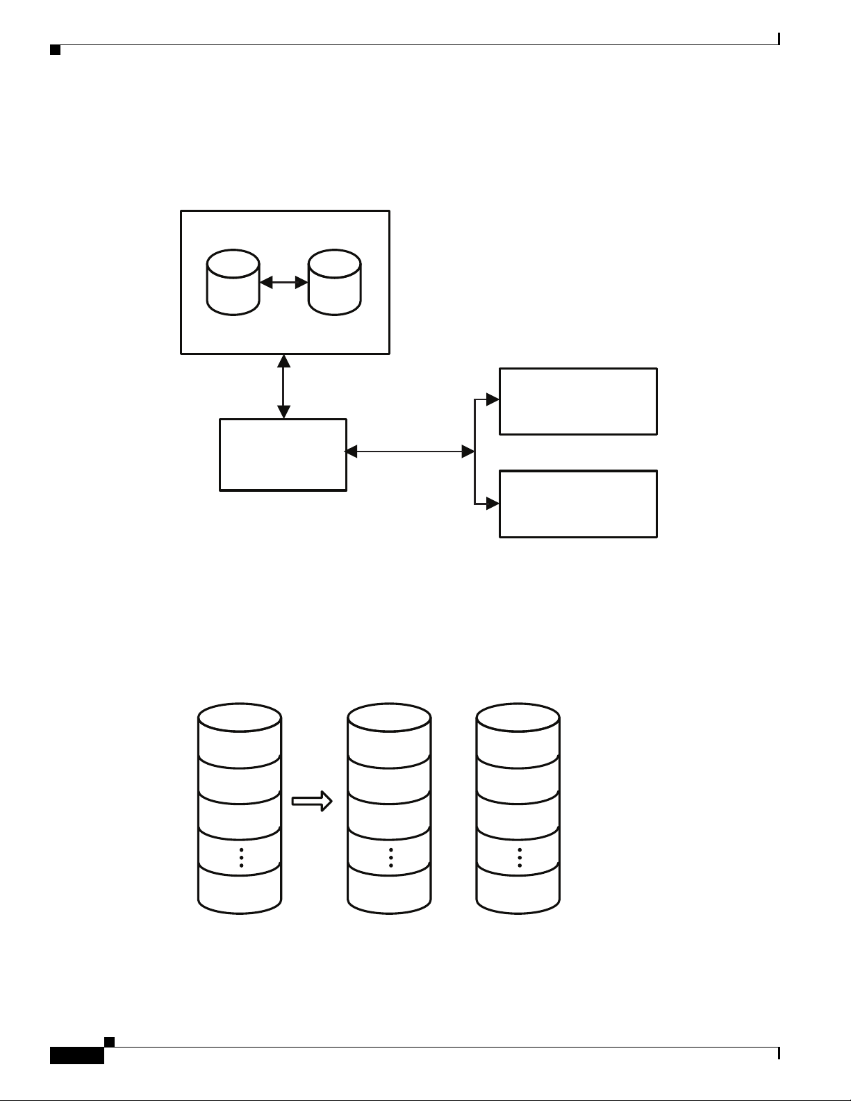
Mirrored Volumes
Primary Mirror
Integrated Mirroring Volume
SAS
LSI
Fusion-MPT
SAS2 Controller
Memory Bus
NVSRAM
(For Write Journaling)
FLASH
(For Configuration)
LBA 1
LBA 2
LBA 3
LBA N
LBA 1
LBA 2
LBA 3
LBA N
LBA 1'
LBA 2'
LBA 3'
LBA N’
+
Physical ViewLogical View
332100
Chapter 4 Configuring the LSI SAS2 Integrated RAID Controller
Host-based status software monitors the state of the mirrored disks and reports any error conditions.
Figure 4-1 shows an Integrated Mirroring volume in which the second disk is a mirrored copy of the data
on the first (primary) disk.
Figure 4-1 Typical Integrated Mirroring Implementation
Figure 4-2 shows the logical view and physical view of an Integrated Mirroring volume. Each logical
block address (LBA) is mirrored on the second disk.
Figure 4-2 Integrated Mirroring Volume
Cisco UCS Servers RAID Guide
4-4
OL-26591-01
Page 49

Chapter 4 Configuring the LSI SAS2 Integrated RAID Controller
Physical ViewLogical View
Mirrored Stripe 1
Mirrored Stripe 2
Mirrored Stripe 3
Mirrored Stripe 4
Mirrored Stripe N
Mirrored Stripe 1
Mirrored Stripe 3
Mirrored Stripe 5
Mirrored Stripe 7
Mirrored Stripe N-1
+
Mirrored Stripe 1'
Mirrored Stripe 3'
Mirrored Stripe 5'
Mirrored Stripe 7'
Mirrored Stripe N-1'
+
Mirrored Stripe 2
Mirrored Stripe 4
Mirrored Stripe 6
Mirrored Stripe 8
Mirrored Stripe N
+
Mirrored Stripe 2'
Mirrored Stripe 4'
Mirrored Stripe 6'
Mirrored Stripe 8'
Mirrored Stripe N'
You can configure an Integrated Mirroring Enhanced volume with up to ten mirrored disks. Figure 4-3
shows the logical view and physical view of an Integrated Mirroring Enhanced volume with three
mirrored disks. The firmware writes each mirrored stripe to a disk and mirrors it to an adjacent disk.
RAID 1E is another term for this type of mirrored configuration.
Figure 4-3 Integrated Mirroring and Striping with Three Mirrored Disks
Mirrored Volumes
Physical ViewLogical View
Mirrored Stripe 1
Mirrored Stripe 2
Mirrored Stripe 3
Mirrored Stripe 4
Mirrored Stripe N
Mirrored Stripe 1
Mirrored Stripe 2'
Mirrored Stripe 4
Mirrored Stripe 5'
Mirrored Stripe N-1'
Mirrored Stripe 1'
Mirrored Stripe 3
Mirrored Stripe 4'
+
Mirrored Stripe 6
Mirrored Stripe N
Mirrored Stripe 2
Mirrored Stripe 3'
Mirrored Stripe 5
+
Mirrored Stripe 6'
Mirrored Stripe N'
332101
You can configure an Integrated Mirroring and Striping volume with an even number of disks, ranging
from a minimum of four to a maximum of ten. Figure 4-4 shows the logical and physical views of an
Integrated Mirroring and Striping volume with four mirrored disks. The firmware writes each mirrored
stripe to a disk and mirrors it to an adjacent disk. RAID 10 is another term for this type of
mirrored/striped configuration.
Figure 4-4 Integrated Mirroring and Striping with Four Mirrored Disks
OL-26591-01
The LSI SAS2 BIOS Configuration Utility enables you to create mirrored volumes during initial setup
and to reconfigure them in response to hardware failures or changes in the environment.
Caution The LSI SAS2 BIOS Configuration Utility deletes all existing data from the disks drives when you
choose to use the drives for a mirrored volume.
Cisco UCS Servers RAID Guide
4-5
Page 50

Mirrored Volumes
Mirrored Volume Features
This section lists the features of Integrated Mirroring, Integrated Mirroring and Striping, and Integrated
Mirroring Enhanced volumes. You can configure one or two mirrored volumes on each LSI SAS2
controller.
• Resynchronization with Concurrent Host I/O Operation
The Integrated RAID firmware allows host I/O transactions to continue on a mirrored volume while
it resynchronizes the volume in the background. The firmware automatically starts resynchronizing
data after a disk failure activates a hot spare or after a disk in a mirrored volume has been hot
swapped.
• Hot Swapping
The Integrated RAID firmware supports hot swapping, and it automatically resynchronizes the
hot-swapped disk in the background without any host or user intervention. The firmware detects
hot-swap removal and disk insertion.
Following a hot-swap event, the firmware verifies that the new physical disk has enough capacity
for the mirrored volume. The firmware resynchronizes all replaced hot-swapped disks, even if the
same disk is reinserted. In a mirrored volume with an even numbers of disks, the firmware marks
the hot-swapped disk as a secondary disk and the other disk with data as the primary disk. The
firmware resynchronizes all data from the primary disk onto the new secondary disk. In a mirrored
volume with an odd number of disks, primary and secondary sets include three disks instead of two.
• Hot Spare Disk
Chapter 4 Configuring the LSI SAS2 Integrated RAID Controller
You can configure two disks as global hot spare disks to protect data on the mirrored volumes
configured on the SAS2 controller. If the Integrated RAID firmware fails one of the mirrored disks,
it automatically replaces the failed disk with a hot spare disk and resynchronizes the mirrored data.
The firmware automatically receives a notification when a hot spare replaces the failed disk, and it
then designates that disk as the new hot spare.
• Online Capacity Expansion
The online capacity expansion (OCE) feature enables you to expand the capacity of an existing
two-disk Integrated Mirroring (RAID 1) volume by replacing the original disk drives with
higher-capacity drives that have the same protocol (SAS or SATA).
Note The OCE feature is not supported with the 1064E-based controller.
Note The new drives must have at least 50 GB more capacity than the original drives of the volume.
After you replace the disk drives and run the OCE command, you must use a commercial tool that
is specific to the operating system to move or increase the size of the partition on the volume.
• Media Verification
The Integrated RAID firmware supports a background media verification feature that runs at regular
intervals when the mirrored volume is in the Optimal state. If the verification command fails for any
reason, the firmware reads the other disk’s data for this segment and writes it to the failing disk in
an attempt to refresh the data. The firmware periodically writes the current media verification
logical block address to nonvolatile memory so that the media verification can continue from where
it stopped prior to a power cycle.
4-6
• Disk Write Caching
Cisco UCS Servers RAID Guide
OL-26591-01
Page 51

Chapter 4 Configuring the LSI SAS2 Integrated RAID Controller
By default, the Integrated RAID firmware disables disk write caching for mirrored volumes to
ensure that the write journal entry stored in the nonvolatile static RAM (NVSRAM) is always valid.
If you enable disk write caching (not recommended), you might cause the disk write log to be
invalid.
• NVSRAM Usage
The Integrated RAID firmware requires at least a 32-KB NVSRAM to perform write journaling for
mirrored volumes on LSI SAS2 controllers. The NVSRAM also preserves configuration information
across reboots. The firmware uses write journaling to verify that the disks in the mirrored volume
are synchronized with each other.
• Background Initialization
Background initialization (BGI) is the process of copying data from primary to secondary disks in
a mirrored volume. The Integrated RAID firmware starts BGI automatically as a background task
when it creates a volume. The volume remains in the Optimal state while BGI is in progress.
• Consistency Check
A consistency check is a background process that reads data from primary and secondary disks in a
mirrored volume and compares it to make sure that the data is identical on both disks. You can use
the LSI SAS2 BIOS Configuration Utility to run a consistency check on a mirrored volume.
• Make Data Consistent Process
Mirrored Volumes
If enabled in the Integrated RAID firmware, the make data consistent (MDC) process starts
automatically and runs in the background when you move a redundant volume from one SAS
controller to another SAS controller. MDC compares the data on the primary and secondary disks.
If it finds inconsistencies, it copies data from the primary disk to the secondary disk.
Mirroring and Mirroring Enhanced Features
Integrated Mirroring, Integrated Mirroring and Striping, and Integrated Mirroring Enhanced volumes
support the following features:
• Configurations of one or two mirrored volumes on each LSI SAS2 controller. Each volume can
consist of two mirrored disks for an Integrated Mirroring volume; three to ten mirrored disks for an
Integrated Mirroring Enhanced volume; or four, six, eight, or ten mirrored disks for an Integrated
Mirroring and Striping volume.
• Two optional global hot spare disks per LSI SAS2 controller to automatically replace failed disks in
mirrored volumes.
• Ability of mirrored volumes to run in optimal mode or in degraded mode if one mirrored disk in an
Integrated Mirroring volume fails or if one or more mirrored disks fail in an Integrated Mirroring
and Striping volume or Integrated Mirroring Enhanced volume.
• Support for hot swapping.
• Support for online capacity expansion (OCE) for RAID1 volumes. OCE allows you to increase the
size of a RAID1 volume by replacing the existing disk drives with higher-capacity disk drives. Data
is protected during the expansion process, and the RAID1 volume remains online.
OL-26591-01
Note The OCE feature is not supported with the 1064E-based controller.
• Presentation of a single, virtual drive to the operating system for each mirrored volume.
Cisco UCS Servers RAID Guide
4-7
Page 52

Integrated Striping
Chapter 4 Configuring the LSI SAS2 Integrated RAID Controller
• Support for both SAS and SATA disks, although you cannot combine the two types of disks in the
same volume. However, an LSI SAS2 controller can support one volume with SATA disks and a
second volume with SAS disks.
• Automatic background initialization after volume creation.
• Consistency checking.
• Fusion-MPT architecture.
• Menu-driven, BIOS-based configuration utility.
• Error notification, in which the drivers update an OS-specific event log.
• Support for SCSI Enclosure Services (SES) status LED.
• Write journaling, which allows automatic synchronization of potentially inconsistent data after
unexpected power-down situations.
• Use of metadata to store volume configuration on disks in a mirrored volume.
• Automatic background resynchronization while host I/Os continue.
• Background media verification, which ensures that data on mirrored volumes is always accessible.
Integrated Striping
This section provides an overview of the LSI Integrated RAID features that support the creation of
striped arrays.
The LSI Integrated RAID solution enables you to create Integrated Striping volumes for applications that
require the faster performance and increased storage capacity of striping. The low-cost Integrated
Striping feature has many of the advantages of a more expensive RAID striping solution. You can
configure an Integrated Striping volume as the boot disk or as a data disk.
The Integrated Striping solution provides better performance and more capacity than individual disks,
without burdening the host CPU. The firmware distributes host I/O transactions over multiple disks and
presents the disks as a single, logical drive. Striping is transparent to the BIOS, the drivers, and the
operating system.
You can use the LSI SAS2 BIOS CU to configure Integrated Striping volumes. These volumes can
consist of two to ten disks.
On Integrated Striping volumes, the firmware writes data across multiple disks instead of onto one disk
by partitioning the storage space of each disk into 64-KB stripes. The firmware interleaves the stripes
round-robin so that the combined storage space consists alternately of stripes from each disk.
Figure 4-5 shows an example of integrated striping: the firmware writes segment 1 to disk 1, segment 2
to disk 2, segment 3 to disk 3, and so on. When the firmware reaches the end of the disk list, it continues
writing data at the next available segment of disk 1.
4-8
Cisco UCS Servers RAID Guide
OL-26591-01
Page 53

Chapter 4 Configuring the LSI SAS2 Integrated RAID Controller
Physical ViewLogical View
+
Stripe 1
Stripe 2
Stripe 3
Stripe N
Stripe 1
Stripe 4
Stripe 7
Stripe N-2
Stripe 2
Stripe 5
Stripe 8
Stripe N-1
+
Stripe 3
Stripe 6
Stripe 9
Stripe N
332104
Figure 4-5 Integrated Striping Example
Integrated Striping
LSI SAS2
Controller
SAS
Disk 1
Segment 1
Segment 5
Segment 9
Figure 4-6 shows a logical view and a physical view of an Integrated Striping volume with three disks.
Figure 4-6 Integrated Striping—Logical and Physical Views
Disk 2
Segment 2
Segment 6
Segment 10
Disk 3 Disk 4
Segment 3
Segment 7
Segment 11
Segment 4
Segment 8
Segment 12
332103
Speed is the primary advantage of the Integrated Striping solution because it transfers data to or from
multiple disks simultaneously. However, there is no data redundancy. You should back up the data on
other media to avoid losing unsaved data if one disk fails.
Integrated Striping Features
OL-26591-01
Integrated Striping supports the following features:
• Support for volumes with two to ten disks.
• Support for two Integrated Striping volumes with up to 14 drives total on a SAS2 controller.
Cisco UCS Servers RAID Guide
4-9
Page 54

Creating Mirrored Volumes
• Support for combining one Integrated Striping volume and one Integrated Mirroring, Integrated
Mirroring and Striping, or Integrated Mirroring Enhanced volume on a single controller.
• Support for both SAS and SATA drives, although you cannot combine the two types of drives in one
volume.
• Fusion-MPT architecture.
• Easy-to-use SAS BIOS configuration utility.
• Error notification.
• Disk write caching, which is enabled by default on all Integrated Striping volumes.
• Use of metadata to store volume configurations on disks.
• OS-specific event log.
• Error display inside the Fusion-MPT BIOS.
• SCSI Enclosure Services (SES) status LED support for drives used in Integrated Striping volumes.
Creating Mirrored Volumes
Chapter 4 Configuring the LSI SAS2 Integrated RAID Controller
The LSI SAS2 BIOS Configuration Utility is a menu-driven utility program that enables you to easily
configure and manage Integrated RAID volumes. You can use the LSI SAS2 BIOS Configuration Utility
to create one or two mirrored volumes on each LSI SAS2 controller, with up to two optional global hot
spare disks. You must connect all disks in a mirrored volume to the same LSI SAS2 controller.
Although you can use different sized disks in mirrored volumes, the smallest disk in the volume
determines the logical size of all disks in the volume. The volume does not use the excess space of the
higher-capacity member disks. For example, if you create an Integrated Mirroring Enhanced volume
with two 100-GB disks and two 120-GB disks, the volume uses only 100 GB on each of the 120-GB
disks.
See Mirrored Volumes, page 4-3, for more information about the features of Integrated Mirroring,
Integrated Mirroring and Striping, and Integrated Mirroring Enhanced volumes.
Launching the LSI SAS2 BIOS Configuration Utility
The LSI SAS2 BIOS Configuration Utility is part of the Fusion-MPT BIOS.
Step 1 The BIOS loads during the startup sequence. After a message appears about the LSI Configuration
Utility, press Ctrl-C to start the LSI SAS2 BIOS Configuration Utility.
• Next, the message changes to
Please wait, invoking SAS Configuration Utility...
• After a brief pause, the Adapter List window (main menu) of the LSI SAS2 BIOS Configuration
Utility appears.
However, on some systems the following message appears:
LSI Corp Configuration Utility will load following initialization!
4-10
In this case, the LSI SAS2 BIOS Configuration Utility loads after the system completes its power-on
self test (POST).
Cisco UCS Servers RAID Guide
OL-26591-01
Page 55

Chapter 4 Configuring the LSI SAS2 Integrated RAID Controller
Once you launch the LSI SAS2 BIOS Configuration Utility, you can complete one of the following tasks:
• Creating an Integrated Mirroring Volume, page 4-11
• Creating an Integrated Mirroring Enhanced or Integrated Mirroring and Striping Volume, page 4-13
• Creating Hot Spare Disks, page 4-15
• Deleting Hot Spare Disks, page 4-15
Creating Mirrored Volumes
You can configure one or two Integrated Mirroring, Integrated Mirroring and Striping, and Integrated
Mirroring Enhanced volumes on each LSI SAS2 controller. You can also configure one mirrored volume
and one Integrated Striping volume on the same controller, which means that you can configure up to a
maximum of 14 disk drives for the two volumes. This number includes one or two optional hot spare
disks for the mirrored volume.
• All physical disks in a volume must be either SATA (with extended command set support) or SAS
(with SMART support).
Creating Mirrored Volumes
Note You cannot combine SAS and SATA disks in the same volume. However, you can create one
volume with SAS disks and a second volume with SATA disks on the same controller.
• Disks must have 512-B blocks and must not have removable media.
• Integrated mirroring volumes must have two disks, Integrated Mirroring Enhanced volumes can
have three to ten disks, and Integrated Mirroring and Striping volumes can have an even number of
disks ranging from four to ten disks.
Note We strongly recommend that you create global hot spare disks for all mirrored volumes to increase the
level of data protection. If a disk in a mirrored volume fails, the Integrated RAID firmware rebuilds it
by using one of the global hot spares, and the data is safe. If you create two mirrored volumes on an
LSI SAS2 controller, either of the two mirrored volumes can use the global hot spares if a disk fails.
Creating an Integrated Mirroring Volume
Step 1 Start the SAS2 BIOS CU as shown in Launching the LSI SAS2 BIOS Configuration Utility, page 4-10.
Step 2 In the Adapter List window, use the arrow keys to choose an LSI SAS adapter and press Enter.
The Adapter Properties window appears, as Figure 4-7 shows.
OL-26591-01
Cisco UCS Servers RAID Guide
4-11
Page 56

Creating Mirrored Volumes
Figure 4-7 Adapter Properties Window
Chapter 4 Configuring the LSI SAS2 Integrated RAID Controller
Step 3
Use the arrow keys to choose RAID Properties, and press Enter.
The Create Array window appears.
Step 4 Choose Create RAID 1 Volume.
The Create New Array window appears.
Step 5 Move the cursor to the RAID Disk column and choose a line that has a No entry in this column,
indicating that the disk is not already part of the volume that you are creating. To add the disk to the new
array, press Spacebar to change No to Yes .
This is the Primary disk in the array.
Caution The SAS2 BIOS CU deletes all existing data from the disks drives when you choose them to use in a
mirrored volume.
Step 6 To add the second disk to the array, move the cursor to another line and press Spacebar.
This is the Secondary disk in the array.
Step 7 To create the array, press C.
A menu window appears.
Step 8 From the menu options, choose Save changes then exit this menu.
A processing message appears briefly, and the SAS2 BIOS CU returns to the Adapter Properties
window. Initialization of the new array continues in the background.
4-12
Note To create a second Integrated Mirroring volume, repeat these instructions starting with Step 3.
To create an Integrated Mirroring Enhanced or Integrated Mirroring and Striping volume, follow the
steps in Creating an Integrated Mirroring Enhanced or Integrated Mirroring and Striping Volume,
page 4-13.
Cisco UCS Servers RAID Guide
OL-26591-01
Page 57

Chapter 4 Configuring the LSI SAS2 Integrated RAID Controller
Creating Mirrored Volumes
Note To create one or two global hot spares, follow the steps in Managing Hot Spare Disks, page 4-15.
Creating an Integrated Mirroring Enhanced or Integrated Mirroring and Striping Volume
Integrated Mirroring Enhanced volumes can have from three to ten physical disks. Data is written to a
disk and mirrored on an adjacent disk. Integrated Mirroring and Striping volumes can have a minimum
of four and a maximum of ten physical disks, in even numbers. In an Integrated Mirroring Enhanced or
Integrated Mirroring and Striping volume, the data is both mirrored and striped.
Step 1 Start the SAS2 BIOS CU as shown in Launching the LSI SAS2 BIOS Configuration Utility, page 4-10.
Step 2 In the Adapter List window, use the arrow keys to choose an LSI SAS adapter and press Enter.
The Adapter Properties window appears, as Figure 4-7 shows.
Step 3 Use the arrow keys to choose RAID Properties and press Enter.
The Create Array window appears.
Step 4 Choose Create RAID 1E Volume.
The Create New Array window appears.
Step 5 Move the cursor to the RAID Disk column and choose a line that has a No entry in this column,
indicating that the disk is not already part of the volume that you are creating. To add the disk to the new
array, press Spacebar to change No to Ye s .
Caution The SAS2 BIOS CU deletes all existing data from the disk drives when you choose the drives to use for
a mirrored volume.
Step 6 Move the cursor to another line and press Spacebar to add another disk to the array:
• If you choose an odd number of disks, the SAS2 BIOS CU creates an Integrated Mirroring Enhanced
array.
• If you choose an even number of disks, it creates an Integrated Mirroring and Striping array. As you
add disks, the Array Size field changes to reflect the size of the new array.
Step 7 To create the array, press C.
A menu window appears.
Step 8 From the menu options, choose Save changes then exit this menu.
A processing message appears briefly, and the SAS2 BIOS CU returns to the Adapter Properties
window. Initialization of the new array continues in the background.
Note To create a second Integrated Mirroring Enhanced or Integrated Mirroring and Striping volume, repeat
the instructions above starting with Step 3.
OL-26591-01
Cisco UCS Servers RAID Guide
4-13
Page 58

Creating Mirrored Volumes
Note To create one or two global hot spares, follow the steps in Managing Hot Spare Disks, page 4-15.
Expanding an Integrated Mirroring Volume with OCE
You can use the online capacity expansion (OCE) feature to expand the capacity of a two-disk Integrated
Mirroring (RAID1) volume by replacing the original disks with two higher-capacity disk drives while
the volume remains online. This process maintains data integrity at all times, even if one of the disks
fails during the replacement process. The new disks must have at least 50 GB more capacity than the
disks they are replacing, and they must use the same protocol (SAS or SATA) as the disks they are
replacing.
Note The OCE feature is not supported with the 1064E-based controller.
Step 1 Physically replace one of the two volume disk drives with a drive that has at least 50 GB more capacity.
If necessary, you can identify the disks in the volume by following the instructions in Locating Disk
Drives in a Volume, page 4-22.
Step 2 Wait until synchronization completes on the new disk and the volume returns to the Optimal state, as
indicated in the Adapter Properties window.
Chapter 4 Configuring the LSI SAS2 Integrated RAID Controller
Step 3 Physically replace the other volume disk drive with a drive that has at least 50 GB more capacity.
Step 4 Wait until synchronization completes on the new disk and the volume returns to the Optimal state.
Step 5 In the Adapter List window of the SAS2 BIOS CU, use the arrow keys to choose the LSI SAS adapter
with the RAID 1 volume and press Enter.
The Adapter Properties window appears.
Step 6 Use the arrow keys to choose RAID Properties, and press Enter.
The Select New Array Type window appears.
Step 7 Choose View Existing Array.
The View Array window appears. If necessary, press Alt-N to switch to the RAID 1 volume with the
new, higher-capacity disk drives.
Step 8 Choose Manage Array.
The Manage Array window appears.
Step 9 Choose Online Capacity Expansion.
A menu window appears with a warning message and with options to start the expansion process or quit.
Step 10 To start the expansion, press Y.
When the expansion process completes, the RAID Properties window appears.
Step 11 Run a commercial tool that is specific to the operating system to move or increase the size of the partition
on the newly expanded RAID 1 volume.
4-14
Cisco UCS Servers RAID Guide
OL-26591-01
Page 59

Chapter 4 Configuring the LSI SAS2 Integrated RAID Controller
Managing Hot Spare Disks
You can create one or two global hot spare disks to protect the data on mirrored volumes on an LSI SAS2
controller. You can also delete hot spare disks.
Creating Hot Spare Disks
Step 1 Start the LSI SAS2 BIOS Configuration Utility as shown in Launching the LSI SAS2 BIOS
Configuration Utility, page 4-10.
Step 2 In the Adapter List window, use the arrow keys to choose an LSI SAS adapter and press Enter.
The Adapter Properties window appears, as Figure 4-7 shows.
Step 3 Use the arrow keys to choose RAID Properties, and press Enter.
The Select New Array Type window appears.
Step 4 Choose View Existing Array.
The View Array window appears. If necessary, press Alt-N to switch to another array on this adapter.
Step 5 Choose Manage Array.
The Manage Array window appears.
Creating Mirrored Volumes
Step 6 Choose Manage Hot Spares, which is the first option.
The Manage Hot Spares window appears.
Step 7 Identify a disk that is not part of a RAID volume (that is, the value in the Drive Status column is not
RAID) and that is not already identified as a hot spare disk.
A global hot spare disk must have 512-byte blocks and nonremovable media. The disk type must be
either SATA with extended command set support or SAS with SMART support.
Step 8 Choose the Hot Spr (Hot Spare) field for this disk and press Spacebar.
The Hot Spare status changes to Yes .
Step 9 (Optional) Repeat Step 8 to choose a second global hot spare disk.
Step 10 To create the hot spare disk, press C.
A menu window appears. An error message appears if the chosen disk is not at least as large as the
smallest disk used in the existing volume. An error message also appears if you try to add a SATA disk
as a hot spare for volumes that use SAS disks, or if you try to add a SAS disk as a hot spare for volumes
that use SATA disks.
Step 11 Choose Save changes then exit this menu to create the hot spare disk.
The SAS2 BIOS CU pauses while it configures the global hot spares.
Deleting Hot Spare Disks
OL-26591-01
Step 1 Access the Manage Hot Spares window by following Step 1 through Step 6 of Expanding an Integrated
Mirroring Volume with OCE, page 4-14.
Step 2 Choose a hot spare disk for deletion, and press C.
Step 3 Choose Save changes then exit this menu to commit the changes.
Cisco UCS Servers RAID Guide
4-15
Page 60

Creating Mirrored Volumes
The SAS2 BIOS CU pauses while it removes the global hot spare.
Other Configuration Tasks
This section describes how to perform other configuration and maintenance tasks for mirrored volumes.
Viewing Volume Properties
Step 1 In the SAS2 BIOS CU, choose an LSI SAS2 adapter from the Adapter List.
The Adapter Properties window appears.
Step 2 Choose RAID Properties.
The Select New Array Type window appears.
Step 3 Choose View Existing Array.
The View Array window appears, showing information about the array and each disk in it. The window
includes global hot spare information, if any exists.
Chapter 4 Configuring the LSI SAS2 Integrated RAID Controller
Note If you create one volume using SAS disks, another volume using SATA disks, and one or two global hot
spare disks, the hot spare disks only appear when you view the mirrored volume that uses the same type
of disks as the hot spare disks.
Step 4 If the currently displayed array is not the one you want, press Alt-N to view another array in the adapter.
Running a Consistency Check
Use the Consistency Check command to verify that the data is synchronized in the mirrored disks in the
volume.
Step 1 In the Adapter List window, use the arrow keys to choose an LSI SAS adapter.
The Adapter Properties window appears.
Step 2 Use the arrow keys to choose RAID Properties, and press Enter.
The Select New Array Type window appears.
Step 3 Choose View Existing Array.
The View Array window appears. If necessary, press Alt-N to switch to another array on this adapter.
Step 4 Choose Manage Array.
The Manage Array window appears.
4-16
Step 5 Choose Consistency Check in the Manage Array window.
A menu window appears.
Step 6 Press Y to start the consistency check.
Cisco UCS Servers RAID Guide
OL-26591-01
Page 61
Chapter 4 Configuring the LSI SAS2 Integrated RAID Controller
The consistency check runs a read-read-compare algorithm in the background. If it encounters any data
miscompares, it stores the information in a bad block table.
Activating an Array
A volume (array) can become inactive if, for example, you remove it from one controller or computer
and install it on a different one. The Activate Array option allows you to reactivate an inactive volume.
This option is available only when the chosen volume is currently inactive.
Step 1 In the Adapter List window, use the arrow keys to choose an LSI SAS adapter and press Enter.
The Adapter Properties window appears.
Step 2 Choose RAID Properties, and press Enter.
The Select New Array Type window appears.
Step 3 Choose View Existing Array.
The View Array window appears. If necessary, press Alt + N to switch to another array on this adapter.
Creating Mirrored Volumes
Step 4 Choose Manage Array.
Step 5 Choose Activate Array in the Manage Array window.
Step 6 Press Y to activate the array.
Deleting an Array
Caution Before you delete an array, be sure to back up all data on the array that you want to keep.
Step 1 In the Adapter List window, use the arrow keys to choose an LSI SAS adapter.
Step 2 Use the arrow keys to choose RAID Properties, and press Enter.
Step 3 Choose View Existing Array.
The Manage Array window appears.
A menu window appears.
The array becomes active after a pause.
The Adapter Properties window appears.
The Select New Array Type window appears.
OL-26591-01
The View Array window appears. If necessary, press Alt + N to switch to another array on this adapter.
Step 4 Choose Manage Array.
The Manage Array window appears.
Step 5 Choose Delete Array.
A menu window appears.
Step 6 Press Y to delete the array, or press N to cancel the deletion process.
Cisco UCS Servers RAID Guide
4-17
Page 62

Creating Mirrored Volumes
After a pause, the utility deletes the array. If there is another remaining array and one or two hot spare
disks, the BIOS checks the hot spare disks to determine if they are compatible with the remaining
volume. If they are not compatible (too small or wrong disk type), the BIOS deletes them also.
Locating Disk Drives in a Volume
You can use the SAS2 BIOS CU to locate and identify a specific physical disk drive in a disk enclosure
by flashing the drive’s LED. You can also flash the LEDs of all the disk drives in a RAID volume, if they
are in a disk enclosure.
When you add a disk drive to a new mirrored volume, the LED on the disk drive starts flashing. The LED
stops flashing when you finish creating the volume.
Step 1 Choose the desired SAS2 controller in the Adapter List window and press Enter.
The Adapter Properties window appears.
Step 2 Highlight SAS Topology and press Enter.
The SAS Topology window appears.
Step 3 Choose the disk in the Device Identifier column and press Enter.
Chapter 4 Configuring the LSI SAS2 Integrated RAID Controller
The LED on the disk flashes until you press a key to stop it.
Step 4 Choose the volume in the left column of the SAS Topology window and press Enter to identify all the
disk drives in a volume.
The LEDs flash on all disk drives in the volume until you press a key to stop them.
Note The LEDs on the disk drives flash as previously described if the firmware configuration is correct and
the drives are in a disk enclosure.
Choosing a Boot Disk
You can choose a boot disk in the SAS Topology window. The next time you boot the computer, the
firmware moves this disk to scan ID 0, making it the new boot disk, which makes it easier to set BIOS
boot device options and to keep the boot device constant during device additions and removals. You can
also choose an alternative boot device. If the BIOS cannot find the preferred boot device when it loads,
it attempts to boot from the alternate device.
Step 1 In the SAS2 BIOS CU, choose an adapter from the Adapter List.
Step 2 Choose the SAS Topology option. If a device is currently designated as the boot device, the Device Info
column in the SAS Topology window lists the word Boot, as shown in Figure 4-8.
4-18
Cisco UCS Servers RAID Guide
OL-26591-01
Page 63

Chapter 4 Configuring the LSI SAS2 Integrated RAID Controller
Figure 4-8 Boot Device on the SAS Topology Window
Creating Integrated Striping Volumes
If a device is currently designated as the alternate boot device, the Device Info column shows the word
Alt.
Step 3 Move the cursor to the disk and press Alt-B to choose the preferred boot disk.
Step 4 Move the cursor to the current boot disk and press Alt-B to remove the boot designator.
This controller no longer has a disk designated as boot.
Step 5 Move the cursor to the new boot disk and press Alt-B to change the boot disk.
The Boot designator moves to this disk.
Step 6 Move the cursor to the disk and press Alt-A to choose an alternate boot disk.
Note Follow Step 4 and Step 5 to change the alternate boot device from one disk to another, but use Alt-A
instead of Alt-B.
Creating Integrated Striping Volumes
This section describes how to create Integrated Striping volumes using the LSI SAS2 BIOS
Configuration Utility (SAS2 BIOS CU).
The LSI SAS2 BIOS CU is a menu-driven utility program that enables you to easily configure and
manage Integrated RAID volumes. You can use the SAS2 BIOS CU to create one or two Integrated
Striping volumes on each LSI SAS2 controller. Each volume can have from two to ten drives. All disks
in an Integrated Striping volume must be connected to the same LSI SAS2 controller.
OL-26591-01
Cisco UCS Servers RAID Guide
4-19
Page 64

Creating Integrated Striping Volumes
Although you can use disks of different sizes in Integrated Striping volumes, the smallest disk in the
volume determines the logical size of all disks in the volume. The firmware does not use the excess space
of the higher-capacity member disk. For example, if you create an Integrated Striping volume with two
100-GB disks and two 120-GB disks, the firmware uses only 100 GB on each of the 120-MB disks for
the volume. The supported stripe size is 64 KB.
See Integrated Striping, page 4-8 for more information about Integrated Striping volumes.
You can configure one or two Integrated RAID volumes on each LSI SAS2 controller. For a two-volume
configuration, you can have two Integrated Striping (RAID 0) volumes, two mirrored volumes, or one
volume of each type. The two volumes can have a maximum of 14 disk drives, which includes one or
two hot spare disks for mirrored volumes.
The following guidelines apply when creating an Integrated Striping volume:
• All physical disks in an Integrated Striping volume must be either SATA (with extended command
set support) or SAS (with SMART support). You cannot combine SAS and SATA disks in the same
volume. However, you can create one volume with SAS disks and a second volume with SATA disks
on the same controller.
• Disks must have 512-B blocks and must not have removable media.
• Integrated Striping volumes must have at least two disks and no more than ten disks. Integrated
Striping volumes do not support hot spare disks.
Chapter 4 Configuring the LSI SAS2 Integrated RAID Controller
Step 1 In the Adapter List window, choose an LSI SAS adapter and press Enter.
The Adapter Properties window appears as seen in Figure 4-7.
Step 2 Choose RAID Properties and press Enter.
The Create Array window appears.
Step 3 Choose Create RAID 0 Volume.
The Create New Array window appears.
Step 4 Move the cursor to the RAID Disk column and choose a line that has a No entry in this column, which
indicates that the disk is not already part of the volume you are creating.
To add the disk to the new array, press Spacebar to change the No to Yes .
Step 5 Move the cursor to another line and press Spacebar to add another disk to the array.
Step 6 Continue adding disks in this way until you have added the desired number of disks.
Step 7 Press C to create the array.
A menu appears.
Step 8 From the menu options, choose Save changes then exit this menu.
A processing message appears briefly, and the SAS2 BIOS CU returns to the Adapter Properties
window. Initialization of the new array continues in the background.
Note Repeat the previous instructions to create a second Integrated Striping volume, if desired, and if enough
additional disks are available.
4-20
Cisco UCS Servers RAID Guide
OL-26591-01
Page 65

Chapter 4 Configuring the LSI SAS2 Integrated RAID Controller
Other Configuration Tasks
This section describes how to perform other configuration and maintenance tasks for Integrated Striping
volumes.
Viewing Volume Properties
Step 1 In the SAS2 BIOS CU, choose an LSI SAS2 adapter from the Adapter List.
The Adapter Properties window appears.
Step 2 Choose RAID Properties.
The Select New Array Type window appears.
Step 3 Choose View Existing Array.
The View Array window appears, showing information about the array and each disk in it.
Step 4 If the currently displayed array is not the one you want, press Alt-N to view another array on the adapter.
Creating Integrated Striping Volumes
Activating an Array
A volume (array) can become inactive if, for example, you remove it from one controller or computer
and install it on a different one. The Activate Array option allows you to reactivate an inactive volume.
This option is available only when the chosen volume is currently inactive.
Step 1 In the Adapter List window, use the arrow keys to choose an LSI SAS adapter and press Enter.
The Adapter Properties window appears.
Step 2 Choose RAID Properties, and press Enter.
The Select New Array Type window appears.
Step 3 Choose View Existing Array.
The View Array window appears. If necessary, press Alt-N to switch to another array on this adapter.
Step 4 Choose Manage Array.
The Manage Array window appears.
Step 5 Choose Activate Array in the Manage Array window.
A menu window appears.
Step 6 Press Y to activate the array.
The array becomes active after a pause.
Deleting an Array
Caution Before you delete an array, be sure to back up the data.
OL-26591-01
Cisco UCS Servers RAID Guide
4-21
Page 66

Creating Integrated Striping Volumes
Step 1 In the Adapter List window, use the arrow keys to choose an LSI SAS adapter.
The Adapter Properties window appears.
Use the arrow keys to choose RAID Properties, and press Enter.
The Select New Array Type window appears.
Step 2 Choose View Existing Array.
The View Array window appears. If necessary, press Alt-N to switch to another array on this adapter.
Step 3 Choose Manage Array.
The Manage Array window appears.
Step 4 Choose Delete Array.
A menu window appears.
Step 5 Press Y to delete the array, or press N to cancel the deletion process.
After a pause, the utility deletes the array.
Chapter 4 Configuring the LSI SAS2 Integrated RAID Controller
Locating Disk Drives in a Volume
You can use the LSI SAS2 BIOS Configuration Utility to locate and identify a specific physical disk
drive in a disk enclosure by flashing the drive’s LED. You can also flash the LEDs of all the disk drives
in a RAID volume, if they are in a disk enclosure.
When you add a disk drive to a new mirrored volume, the LED on the disk drive starts flashing. The LED
stops flashing when you finish creating the volume.
Step 1 Choose the desired SAS2 controller in the Adapter List window and press Enter.
The Adapter Properties window appears.
Step 2 Highlight SAS Topology and press Enter.
The SAS Topology window appears.
Step 3 Choose the disk in the Device Identifier column and press Enter.
The LED on the disk flashes until you press a key to stop it.
Step 4 Choose the volume in the left column of the SAS Topology window and press Enter to identify all the
disk drives in a volume,
The LEDs flash on all disk drives in the volume until you press a key to stop them.
Note The LEDs on the disk drives flash, as previously described, if the firmware configuration is correct and
the drives are in a disk enclosure.
4-22
Cisco UCS Servers RAID Guide
OL-26591-01
Page 67

Chapter 4 Configuring the LSI SAS2 Integrated RAID Controller
Choosing a Boot Disk
You can choose a boot disk in the SAS Topology window. The next time you boot the computer, the
firmware moves this disk to scan ID 0, making it the new boot disk, which makes it easier to set BIOS
boot device options and to keep the boot device constant during device additions and removals. You can
also choose an alternative boot device. If the BIOS cannot find the preferred boot device when it loads,
it attempts to boot from the alternate device.
Step 1 In the LSI SAS2 BIOS Configuration Utility, choose an adapter from the Adapter List.
Step 2 Choose the SAS Topology option. If a device is currently designated as the boot device, the Device Info
column in the SAS Topology window lists the word Boot (see Figure 4-8 on page 4-19).
If a device is currently designated as the alternate boot device, the Device Info column shows the word
Alt.
Step 3 Move the cursor to the disk and press Alt-B to choose the preferred boot disk.
Step 4 Move the cursor to the current boot disk and press Alt-B to remove the boot designator.
This controller no longer has a disk designated as boot.
Step 5 Move the cursor to the new boot disk and press Alt-B to change the boot disk.
Determining Which Controller is in Your Server
The Boot designator moves to this disk.
Step 6 Move the cursor to the disk and press Alt-A to choose an alternate boot disk.
To change the alternate boot device from one disk to another, follow Step 4 and Step 5 in this procedure,
but use Alt-A instead of Alt-B.
Determining Which Controller is in Your Server
Supported RAID controllers for all models are listed in RAID Controllers in UCS Servers, page 3-10.
If you do not have a record of which device is used in the server, you can read the on-screen messages
that are displayed during system bootup. These messages display information about the devices that are
installed in your server.
• Information about the models of card installed are displayed as part of the verbose boot. You are
also prompted to press Ctrl-H to launch configuration utilities for those cards. For servers running
CIMC firmware earlier than release 1.2(1), see also Disabling Quiet Boot for CIMC Firmware
Earlier than Release 1.2(1), page 4-24.
• If a mezzanine-style card is enabled, you are prompted to press Ctrl-C to launch the configuration
for these cards.
• If no models of card are displayed but there is a RAID configuration, your server is using the
onboard ICH10R controller. You are also prompted to press Ctrl-M to launch the configuration
utilities for this controller.
OL-26591-01
Cisco UCS Servers RAID Guide
4-23
Page 68
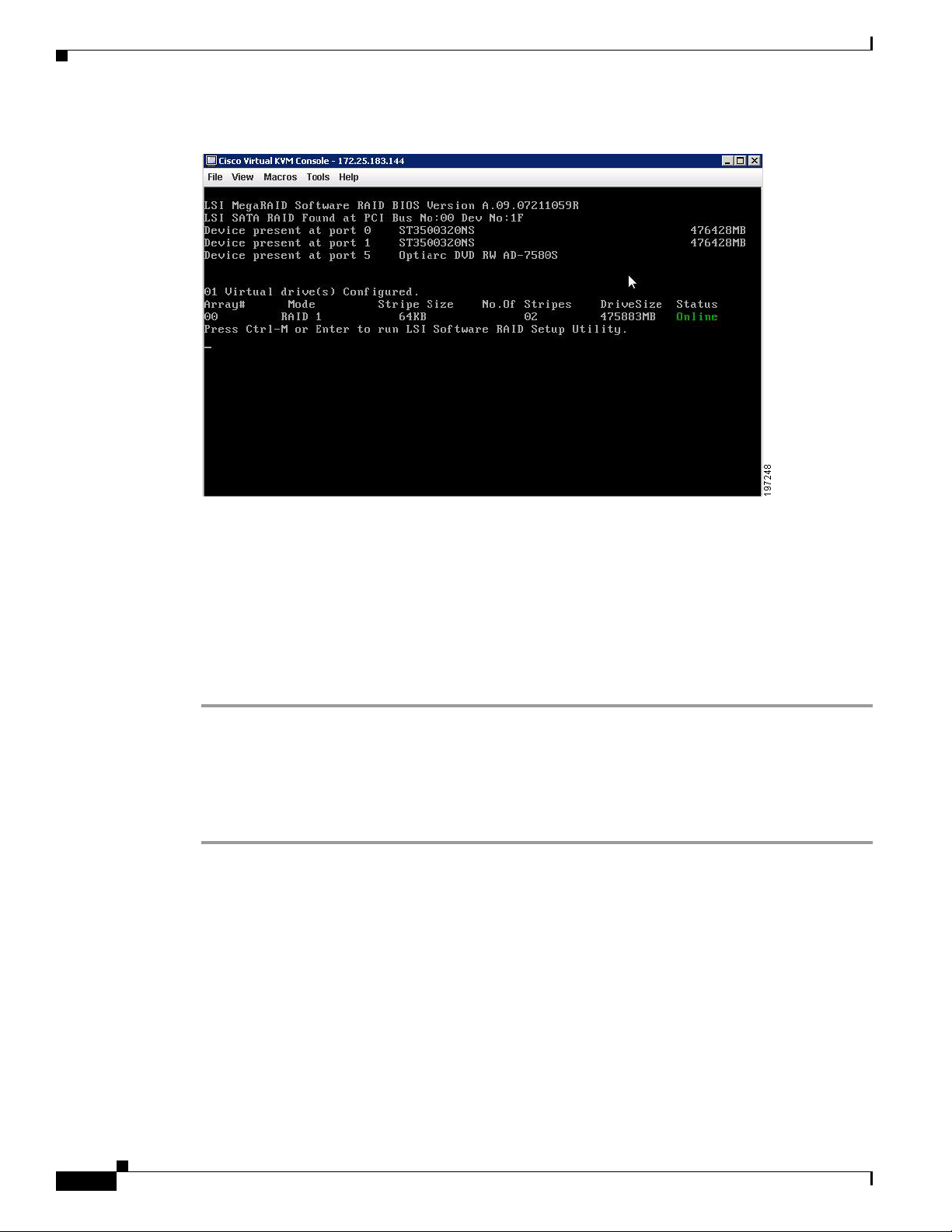
Disabling Quiet Boot for CIMC Firmware Earlier than Release 1.2(1)
Figure 4-9 ICH10R Launch Window
Chapter 4 Configuring the LSI SAS2 Integrated RAID Controller
Disabling Quiet Boot for CIMC Firmware Earlier than Release
1.2(1)
For CIMC firmware and BIOS release 1.2(1) and later releases, Quiet Boot has been removed and is not
required. If you are running CIMC firmware and BIOS earlier than release 1.2(1), you can use the
following procedure to disable Quiet Boot.
Step 1 Boot the server and watch for the F2 prompt during bootup.
Step 2 Press F2 when prompted to enter the BIOS Setup utility.
Step 3 On the Main page of the BIOS Setup utility, set Quiet Boot to Disabled, which allows non-default
messages, prompts, and POST messages to display during bootup instead of the Cisco logo window.
Step 4 Press F10 to save your changes and exit the utility.
Launching Option ROM-Based Controller Utilities
To alter the RAID configurations on your hard drives, you can use your host-based utilities that you
install on top of your host OS, or you can use the LSI option ROM-based utilities that are installed on
the server.
When you boot the server and you have quiet boot disabled (see Disabling Quiet Boot for CIMC
Firmware Earlier than Release 1.2(1), page 4-24), information about your controller is displayed with
the prompts for the key combination to launch the option ROM-based utilities for your controller.
4-24
Watch for the prompt for your controller during verbose boot:
Cisco UCS Servers RAID Guide
OL-26591-01
Page 69

Chapter 4 Configuring the LSI SAS2 Integrated RAID Controller
Restoring RAID Configuration After Replacing a RAID Controller
• The prompt for LSI controller card utility is Ctrl-H.
• The prompt for the mezzanine-style controller cards is Ctrl-C.
• The prompt for the onboard Intel ICH10R controller utility is Ctrl-M.
Note Cisco has also developed the Cisco Server Configuration Utility for C-Series servers, which can assist
you in setting up some RAID configurations for your drives. This utility is shipped with new servers on
CD. You can also download the ISO from Cisco.com. See the user documentation for this utility at the
following URL:
http://www.cisco.com/en/US/docs/unified_computing/ucs/sw/ucsscu/user/guide/20/SCUUG20.html
Restoring RAID Configuration After Replacing a RAID Controller
When you replace a RAID controller, the RAID configuration that is stored in the controller is lost. Use
the following procedure to restore your RAID configuration to your new RAID controller.
Step 1 Replace your RAID controller.
Step 2 If this was a full chassis swap, replace all drives into the drive bays, in the same order that they were
installed in the old chassis.
Step 3 If Quiet Boot is enabled, disable it in the system BIOS. See Disabling Quiet Boot for CIMC Firmware
Earlier than Release 1.2(1), page 4-24.
Step 4 Reboot the server and watch for the prompt to press F.
Step 5 Press F when you see the following on-screen prompt:
Foreign configuration(s) found on adapter.
Press any key to continue or ‘C’ load the configuration utility,
or ‘F’ to import foreign configuration(s) and continue.
Step 6 Press any key (other than C) to continue when you see the following message:
All of the disks from your previous configuration are gone. If this is
an unexpected message, then please power of your system and check your cables
to ensure all disks are present.
Press any key to continue, or ‘C’ to load the configuration utility.
Step 7 Watch the subsequent windows for confirmation that your RAID configuration was imported correctly.
• If you see the following message, your configuration was successfully imported. The LSI virtual
drive is also listed among the storage devices.
N Virtual Drive(s) found on host adapter.
• If you see the following message, your configuration was not imported which can happen if you do
not press F quickly enough when prompted. In this case, reboot the server and try the import
operation again when you are prompted to press F.
0 Virtual Drive(s) found on host adapter.
OL-26591-01
Cisco UCS Servers RAID Guide
4-25
Page 70

Restoring RAID Configuration After Replacing a RAID Controller
Chapter 4 Configuring the LSI SAS2 Integrated RAID Controller
4-26
Cisco UCS Servers RAID Guide
OL-26591-01
Page 71

CHA P T ER
5
LSI MegaRAID SAS Controller Tasks
This chapter describes the LSI WebBIOS Configuration Utility (CU), which operates independently of
the operating system and enables you to create and manage RAID configurations on LSI MegaRAID
SAS controllers.
If your server has an integrated RAID SAS controller, see Chapter 4, “Configuring the LSI SAS2
Integrated RAID Controller.”
This chapter contains the following sections:
• LSI MegaRAID Controller Management Utilities, page 5-1
• LSI WebBIOS CU, page 5-2
• Managing RAID, page 5-16
• Determining Which Controller is in Your Server, page 5-22
• Limitation on Importing Foreign Configuration To a Virtual Disk That is Under Construction,
page 5-25
LSI MegaRAID Controller Management Utilities
LSI offers these three main MegaRAID controller management utilities:
• LSI WebBIOS Configuration Utility
• MegaRAID Command Tool
• MegaRAID Storage Manager Software
The LSI utilities have help documentation for more information about using the utilities.
For basic information on RAID and how to use the LSI utilities, see the following documentation:
Broadcom 12Gb/s MegaRAID SAS Software User Guide
LSI WebBIOS Configuration Utility
The LSI WebBIOS Configuration Utility (CU) operates independently of the operating system and
enables you to create and manage RAID configurations on LSI MegaRAID SAS controllers.
Cisco UCS Servers RAID Guide
OL-26591-01
5-1
Page 72

LSI WebBIOS CU
MegaRAID Command Tool
The LSI MegaRAID Command Tool (CT) is a command-line interface (CLI) utility that enables you to
configure, monitor, and maintain LSI MegaRAID SAS controllers and the devices connected to them.
MegaRAID Storage Manager
The LSI MegaRAID Storage Manager (MSM) is a software application with a graphical user interface
that enables you to configure, monitor, and maintain storage configurations on LSI MegaRAID SAS
controllers.
LSI WebBIOS CU
The LSI WebBIOS CU, unlike the LSI MegaRAID Storage Manager software, resides in the SAS
controller BIOS and operates independently of the operating system.
You can use the WebBIOS CU to do the following tasks:
• Create drive groups and virtual drives for storage configurations.
Chapter 5 LSI MegaRAID SAS Controller Tasks
• Display controller, virtual drive, physical drive, and battery backup unit (BBU) properties, and
change parameters.
• Delete virtual drives.
• Migrate a storage configuration to a different RAID level.
• Detect configuration mismatches.
• Import a foreign configuration.
• Scan devices connected to the controller.
• Initialize virtual drives.
The WebBIOS CU provides a configuration wizard to guide you through the configuration of virtual
drives and drive groups.
Starting the WebBIOS CU
Step 1 When the host computer is booting, the following text appears:
Copyright© LSI Corporation
Press <Ctrl><H> for WebBIOS
Press Ctrl+H.
The Controller Selection window appears.
Step 2 If the system has multiple SAS controllers, choose a controller.
Step 3 Click Start to continue.
The main WebBIOS CU window appears. See Figure 5-1.
5-2
Cisco UCS Servers RAID Guide
OL-26591-01
Page 73

Chapter 5 LSI MegaRAID SAS Controller Tasks
WebBIOS CU Main Menu Window Options
Figure 5-1 shows the window that appears when you start the WebBIOS CU and choose a controller.
Figure 5-1 Main WebBIOS CU Window
LSI WebBIOS CU
Listed in the right pane are the following:
• Virtual drives configured on the controller
• Drives that are connected to the controller
• Drives that are foreign or missing
Note In the list of virtual drives, the drive nodes are sorted based on the order in which you added the drives
to the drive group, rather than the physical slot order that displays in the physical trees.
Note The minimum screen resolution for WebBIOS is 640x480.
Click Physical View or Logical View in the left pane to toggle between the physical view and logical
view of the storage devices connected to the controller. When Physical View appears in the right pane,
it shows the drive groups that are configured on this controller.
For drives in an enclosure, the window shows the following drive information:
• Enclosure
• Slot
• Interface type (such as SAS or SATA)
• Drive type (HDD or SSD)
• Drive size
OL-26591-01
Cisco UCS Servers RAID Guide
5-3
Page 74

LSI WebBIOS CU
Toolbar
Menu Options
Chapter 5 LSI MegaRAID SAS Controller Tasks
• Drive status (such as Online or Unconfigured Good)
The toolbar at the top of the WebBIOS CU contains the following tools, from left to right (see
Figure 3-1):
• Main window—Click to return to the main window from any other WebBIOS CU window.
• Previous—Click to return to the previous window that you were viewing.
• Exit—Click to exit the WebBIOS CU program.
• Turn off alarm—Click to turn off the sound from the onboard controller alarm.
• About—Click to display information about the WebBIOS CU version, browser version, and HTML
interface engine.
These options are located in the left pane of the main WebBIOS CU window (the hotkey shortcut for
each option is shown in parentheses next to the option name):
• Controller Selection (Alt-c)— Views the Controller Selection window, where you can choose a
different SAS controller. You can then view information about the controller and the devices
connected to it, or create a new configuration on the controller.
• Controller Properties (Alt-p)—Views the properties of the currently chosen SAS controller. For
more information, see Table 5-1.
• Scan Devices (Alt-s)—Allows the WebBIOS CU to rescan the physical and virtual drives for any
changes in the drive status or the physical configuration. The WebBIOS CU displays the results of
the scan in the physical and virtual drive descriptions.
• Virtual Drives (Alt-v)—Views the Virtual Drives window, where you can change and view virtual
drive properties, delete virtual drives, initialize drives, and perform other tasks. For more
information, see Viewing Virtual Drive Properties, Policies, and Operations, page 5-13.
• Drives (Alt-d)—Views the Drives window, where you can view drive properties, create hot spares,
and perform other tasks. For more information, see Viewing Physical Drive Properties and
Operations, page 5-14.
• Configuration Wizard (Alt-o)—Starts the Configuration Wizard and creates a new storage
configuration, clear a configuration, or add a configuration. For more information, see Configuring
RAID Drive Groups and Virtual Drives, page 5-5.
• Logical View (Alt-l)—Toggles between the Physical View window and the Logical View window.
• Physical View (Alt-h)—Toggles between the Physical View window and the Logical View window.
• Events (Alt-e)—Views system events in the Event Information window. For more information, see
Managing RAID, page 5-16.
• Exit (Alt+x)—Exits the WebBIOS CU and continue with system boot.
5-4
Cisco UCS Servers RAID Guide
OL-26591-01
Page 75

Chapter 5 LSI MegaRAID SAS Controller Tasks
Configuring RAID Drive Groups and Virtual Drives
This section describes how to use the WebBIOS CU Configuration Wizard to configure RAID drive
groups and virtual drives to create storage configurations.
Choosing the Configuration with the Configuration Wizard
Step 1 Click Configuration Wizard in the left pane of the WebBIOS main window.
The first Configuration Wizard window opens.
Step 2 Choose a configuration type:
Caution If you choose Clear Configuration or New Configuration, all existing data in the configuration is
deleted. Back up data that you want to keep before you choose a configuration type.
• Clear Configuration—Clears the existing configuration.
• New Configuration—Clears the existing configuration and allows you to create a new
configuration.
LSI WebBIOS CU
• Add Configuration—Retains the existing storage configuration and adds new drives to it (this
option does not cause any data loss).
Step 3 Click Next.
The WebBIOS Configuration Method window opens.
Step 4 Choose a configuration method:
• Manual Configuration—Allows you to control all attributes of the new storage configuration as
you create drive groups and virtual drives, and set their parameters.
• Automatic Configuration—Automatically creates an optimal RAID configuration.
If you choose Automatic Configuration, you can choose whether to create a redundant RAID drive
group or a nonredundant RAID 0 drive group. Choose one of the following from the Redundancy
drop-down list:
Redundancy when possible
No redundancy
Step 5 Click Next to continue.
• For Automatic Configuration, continue with Using Automatic Configuration, page 5-5.
• For Manual Configuration, continue with Using Manual Configuration, page 5-6.
Using Automatic Configuration
OL-26591-01
Step 1 When WebBIOS displays the proposed new configuration, review the information in the window, and
click Accept or click Back to change the configuration.
One of the following configuration appears:
Cisco UCS Servers RAID Guide
5-5
Page 76

LSI WebBIOS CU
Step 2 When you are prompted to save the configuration, click Ye s.
Step 3 When you are prompted to initialize the new virtual drives, click Yes .
Chapter 5 LSI MegaRAID SAS Controller Tasks
• RAID 0—If you choose Automatic Configuration and No Redundancy, WebBIOS creates a
RAID 0 configuration.
• RAID 1—If you choose Automatic Configuration and Redundancy when possible, and only two
drives are available, WebBIOS creates a RAID 1 configuration.
• RAID 5—If you choose Automatic Configuration and Redundancy when possible, and three or
more drives are available, WebBIOS creates a RAID 5 configuration.
• RAID 6—If you choose Automatic Configuration and Redundancy when possible, and the RAID
6 option is enabled, and three or more drives are available, WebBIOS creates a RAID 6
configuration.
WebBIOS CU begins a background initialization of the virtual drives.
New RAID 5 virtual drives and new RAID 6 virtual drives require a minimum number of drives for a
background initialization to start. If there are fewer drives, the background initialization does not start.
The following number of drives is required:
• New RAID 5 virtual drives must have at least five drives for a background initialization to start.
• New RAID 6 virtual drives must have at least seven drives for a background initialization to start.
Using Manual Configuration
This section contains the procedures for creating RAID drive groups for RAID levels 0, 1, 5, 6, 00, 10,
50, and 60.
Using Manual Configuration (RAID 0, 1, 5, 6)
For more information about RAID levels, see RAID Levels, page 1-8.
Note RAID level 0 is not fault tolerant. If a drive in a RAID 0 drive group fails, the whole virtual drive (all
drives associated with the virtual drive) fails.
Step 1 Choose Manual Configuration and click Next.
The Drive Group Definition window appears. Use this window to choose drives to create drive groups.
Step 2 Press and hold Ctrl while choosing two or more ready drives in the Drives pane.
Choose all of the drives for the drive group.
Step 3 Click Add To Array to move the drives to a proposed drive group configuration in the Drive Groups
pane.
If you need to undo the changes, click Reclaim.
Step 4 From the Encryption drop-down list, choose an encryption option.
Step 5 If needed, finish adding drives to the Drive Groups pane and click Accept DG.
Step 6 Click Next.
5-6
Cisco UCS Servers RAID Guide
OL-26591-01
Page 77

Chapter 5 LSI MegaRAID SAS Controller Tasks
The Virtual Drive Definition window appears. This window lists the possible RAID levels for the drive
group. Use this window to choose the RAID level, strip size, read policy, and other attributes for the new
virtual drives.
Step 7 Choose the virtual drive options using the drop-down list in the left pane (the default values are shown).
• From the RAID Level drop-down list, choose the desired RAID option (RAID 0, 1, 5, or 6).
All of the possible RAID levels for the virtual drive are listed.
• From the Strip Size drop-down list, choose one of the following:
8, 16, 32, 64, 128, 256, 512, 1024 KB. The default is 64 KB.
The strip size is the portion of a stripe that resides on a single drive in the drive group. The stripe
consists of the data segments that the RAID controller writes across multiple drives, not including
parity drives.
For example, consider a stripe that contains 64 KB of drive space and has 16 KB of data residing on
each drive in the stripe. In this case, the stripe size is 64 KB and the strip size is 16 KB. A larger
strip size produces higher read performance. If your server regularly performs random read requests,
choose a smaller strip size.
• From the Access Policy drop-down list, choose one of the following:
LSI WebBIOS CU
–
RW—Allows read/write access. This is the default.
–
Read Only—Allows read-only access.
–
Blocked—Does not allow access.
• From the Read Policy drop-down list, choose one of the following:
–
Normal—Disables the read-ahead capability. This is the default.
–
Ahead—Enables read-ahead capability, which allows the controller to read sequentially ahead
of requested data and to store the additional data in cache memory, anticipating that the data
will be needed soon. This option speeds up reads for sequential data but there is little
improvement when accessing random data.
• From the Write Policy drop-down list, choose one of the following:
–
WBack—In Writeback mode, the controller sends a data transfer completion signal to the host
when the controller cache has received all of the data in a transaction. This setting is
recommended in Standard mode.
–
WThru—In Writethrough mode, the controller sends a data transfer completion signal to the
host when the drive subsystem has received all of the data in a transaction. This is the default.
–
Bad BBU—Choose this mode if you want the controller to use Writeback mode, but the
controller has no BBU or the BBU is bad. If you do not choose this option, the controller
firmware automatically switches to Writethrough mode if it detects a bad or missing BBU.
Caution The LSI WebBIOS CU allows Writeback mode to be used with or without a battery. We recommend that
you use either a battery to protect the controller cache or an uninterruptable power supply (UPS) to
protect the entire system. If you do not use a battery or a UPS, and there is a power failure, you risk
losing the data in the controller cache.
OL-26591-01
• From the IO Policy drop-down list, choose one of the following:
–
Direct—In direct I/O mode, reads are not buffered in the cache memory. Data is transferred to
the cache and the host concurrently. If the same data block is read again, it comes from the cache
memory. This is the default.
Cisco UCS Servers RAID Guide
5-7
Page 78

LSI WebBIOS CU
Chapter 5 LSI MegaRAID SAS Controller Tasks
–
Cached—In cached I/O mode, all reads are buffered in the cache memory.
The IO Policy applies to reads on a specific virtual drive. It does not affect the read-ahead cache.
• From the Drive Cache drop-down list, choose one of the following:
–
Enable—Enables the drive cache.
–
Disable—Disables the drive cache.
–
NoChange—Leaves the current drive cache policy as is. This is the default.
• From the Disable BGI drop-down list, choose the background initialization status from the
following:
–
No—Leaves background initialization enabled, which means that a new configuration can be
initialized in the background while you use WebBIOS to do other configuration tasks. This is
the default.
–
Ye s—Does not allow background initializations for configurations on this controller.
• From the Select Size drop-down list, choose the size of the virtual drive in MB.
Normally, this would be the full size for RAID 0 shown in the Configuration pane. You can specify
a smaller size if you want to create other virtual drives in the same drive group.
Step 8 Click Accept to accept the changes to the virtual drive definitions.
If you need to undo the changes, click Reclaim.
Step 9 After you finish the virtual drive definitions, click Next.
The Configuration Preview window appears.
Step 10 Check the virtual drive configuration in the Configuration Preview window and choose one of the
following:
• If the virtual drive configuration is acceptable, click Accept to save the configuration.
• Click Back to return to the previous windows and change the configuration.
Step 11 Click Ye s at the prompt to save the configuration.
The main WebBIOS CU window appears.
Using Manual Configuration (RAID 00, 10, 50, 60)
For more information about RAID levels, see RAID Levels, page 1-8.
Step 1 Choose Manual Configuration and click Next.
The Drive Group Definition window appears. Use this window to choose drives to create drive groups.
Step 2 Press and hold Ctrl while choosing ready drives in the Drives pane.
5-8
Choose all of the drives for the drive group.
Step 3 Click Add To Array to move the drives to a proposed drive group configuration in the Drive Groups
pane.
If you need to undo the changes, click Reclaim.
Step 4 If needed, finish adding drives to the Drive Groups pane and click Accept DG to create a RAID drive
group.
An icon for the next drive group appears in the Drive Groups pane.
Cisco UCS Servers RAID Guide
OL-26591-01
Page 79

Chapter 5 LSI MegaRAID SAS Controller Tasks
Step 5 Choose the drive group created in Step 4, and press and hold Ctrl while choosing more ready drives in
the Drives pane to create a second RAID drive group.
Step 6 Click Add To Array to move the drives to a second drive group configuration in the Drive Groups pane.
If you need to undo the changes, click Reclaim.
Note RAID 00 supports a maximum of eight spans with a maximum of 32 drives per span.
Note RAID 10 supports a maximum of eight spans with a maximum of 32 drives per span. You must use an
even number of drives in each RAID 10 drive group in the span.
Step 7 From the Encryption drop-down list, choose an encryption option.
Step 8 If needed, finish adding drives to the Drive Groups pane and click Accept DG to create a RAID 0 drive
group.
Step 9 Repeat Step 4 through Step 6 until you have chosen all the drives you want for the drive groups.
Step 10 After you finish adding drives to the Drive Groups pane, choose each drive group, and click Accept DG
after each drive group choice.
Step 11 Click Next.
The Span Definition window appears. This window shows the drive group holes that you can choose to
add to the Span pane.
LSI WebBIOS CU
Step 12 Press and hold Ctrl while you choose a drive group in the Array With Free Space pane, and click
Add to SPAN.
The drive group you chose appears in the Span pane.
Step 13 Press and hold Ctrl while you choose a second drive group, and click Add to SPAN.
Step 14 Repeat Step 12 and Step 13 until you have chosen all of the drive groups that you need.
Step 15 Click Next.
The Virtual Drive Definition window appears. This window lists the possible RAID levels for the drive
group. Use this window to choose the RAID level, strip size, read policy, and other attributes for the new
virtual drives.
Step 16 Press and hold Ctrl to choose the drive group in the Configuration pane, and then choose the virtual
drive options using the drop-down lists in the left pane (the default values are shown):
• From the RAID Level drop-down list, choose The desired RAID level (RAID 00, 10, 50, or 60).
All of the possible RAID levels for the virtual drive are listed.
• From the Strip Size drop-down list, choose one of the following:
8, 16, 32, 64, 128, 256, 512, 1024 KB. The default is 64 KB.
The strip size is the portion of a stripe that resides on a single drive in the drive group. The stripe
consists of the data segments that the RAID controller writes across multiple drives, not including
parity drives.
For example, consider a stripe that contains 64 KB of drive space and has 16 KB of data residing on
each drive in the stripe. In this case, the stripe size is 64 KB and the strip size is 16 KB. A larger
strip size produces higher read performance. If your server regularly performs random read requests,
choose a smaller strip size.
• From the Access Policy drop-down list, choose one of the following:
OL-26591-01
Cisco UCS Servers RAID Guide
5-9
Page 80

LSI WebBIOS CU
Chapter 5 LSI MegaRAID SAS Controller Tasks
–
RW—Allows read/write access. This is the default.
–
Read Only—Allows read-only access.
–
Blocked—Does not allow access.
• From the Read Policy drop-down list, choose one of the following:
–
Normal—Disables the read-ahead capability. This is the default.
–
Ahead—Enables read-ahead capability, which allows the controller to read sequentially ahead
of requested data and to store the additional data in cache memory, anticipating that the data
will be needed soon. This speeds up reads for sequential data but there is little improvement
when accessing random data.
• From the Write Policy drop-down list, choose one of the following:
–
WBack—In Writeback mode, the controller sends a data transfer completion signal to the host
when the controller cache has received all of the data in a transaction. This setting is
recommended in Standard mode.
–
WThru—In Writethrough mode, the controller sends a data transfer completion signal to the
host when the drive subsystem has received all of the data in a transaction. This is the default.
–
Bad BBU—Choose this mode if you want the controller to use Writeback mode but the
controller has no BBU or the BBU is bad. If you do not choose this option, the controller
firmware automatically switches to Writethrough mode if it detects a bad or missing BBU.
Caution LSI allows Writeback mode to be used with or without a battery. LSI recommends that you use either a
battery to protect the controller cache or an uninterruptable power supply (UPS) to protect the entire
system. If you do not use a battery or a UPS, and there is a power failure, you risk losing the data in the
controller cache.
• From the IO Policy drop-down list, choose one of the following:
–
Direct—In direct I/O mode, reads are not buffered in the cache memory. Data is transferred to
the cache and the host concurrently. If the same data block is read again, it comes from the cache
memory. This is the default.
–
Cached—In cached I/O mode, all reads are buffered in the cache memory.
The IO Policy applies to reads on a specific virtual drive. It does not affect the read-ahead cache.
• From the Drive Cache drop-down list, choose one of the following:
–
Enable—Enables the drive cache.
–
Disable—Disables the drive cache.
–
NoChange—Leaves the current drive cache policy as is. This is the default.
• From the Disable BGI drop-down list, choose the background initialization status from the
following:
–
No—Leaves background initialization enabled, which means that a new configuration can be
initialized in the background while you use WebBIOS to do other configuration tasks. This is
the default.
–
Ye s—Does not allow background initializations for configurations on this controller.
5-10
• From the Select Size drop-down list, choose the size of the virtual drive in MB.
Normally, this would be the full size for RAID 00 shown in the Configuration pane. You can specify
a smaller size if you want to create other virtual drives in the same drive group.
Cisco UCS Servers RAID Guide
OL-26591-01
Page 81

Chapter 5 LSI MegaRAID SAS Controller Tasks
Step 17 Click Accept to accept the changes to the virtual drive definitions.
If you need to undo the changes, click Reclaim.
Step 18 After you finish the virtual drive definitions, click Next.
The Configuration Preview window appears.
Step 19 Check the virtual drive configuration in the Configuration Preview window and choose one of the
following:
• If the virtual drive configuration is acceptable, click Accept to save the configuration.
• Click Back to return to the previous windows and change the configuration.
Step 20 Click Ye s at the prompt to save the configuration.
The main WebBIOS CU window appears.
Viewing and Changing Device Properties
This section describes how you can use the WebBIOS CU to view and change the properties for
controllers, virtual drives, physical drives, and BBUs.
LSI WebBIOS CU
Viewing Controller Properties
WebBIOS displays information for one LSI SAS controller at a time. If your computer system has
multiple LSI SAS controllers, you can view information for a different controller by clicking Controller
Selection in the main window. When the Controller Selection window appears, choose the controller you
want from the list.
To view the properties of the current controller, follow these steps:
Step 1 Click Controller Properties in the main WebBIOS CU window.
There are three Controller Properties windows. The information in the first window is read-only and
cannot be modified directly. The window lists the number of virtual drives that are already defined on
this controller and the number of drives connected to the controller.
Step 2 Click Next to view the second Controller Properties window.
Step 3 Click Next to view the third Controller Properties window.
Table 5 -1 describes the entries and options listed in the second and third Controller Properties windows.
LSI recommends that you leave these options at their default settings to achieve the best performance,
unless you have a specific reason for changing them.
Step 4 If you make changes to the options on these windows, click Submit to register them. If you change your
mind, click Reset to return the options to their default values.
OL-26591-01
Cisco UCS Servers RAID Guide
5-11
Page 82

LSI WebBIOS CU
Chapter 5 LSI MegaRAID SAS Controller Tasks
Table 5-1 Controller Properties Menu Options
Option Description
Battery
Backup
Set Factory
Defaults
Rebuild
Rate
BGI Rate Chooses the amount of system resources dedicated to background initialization of
CC Rate Chooses the amount of system resources dedicated to consistency checks of virtual
Reconstruction
Rate
Controller
BIOS
NCQ Native Command Queuing (NCQ) gives an individual drive the ability to optimize the
Coercion
Mode
SMART
Polling
Alarm
Control
Patrol Read
Rate
Cache Flush
Interval
Spinup Drive
Count
Indicates whether the chosen controller has a BBU. If present, you can click Present
to view information about the BBU. For more information, see Viewing and Changing
Device Properties, page 5-11.
Loads the default MegaRAID WebBIOS CU settings.
The default is No.
Chooses the rebuild rate for drives connected to the chosen controller. The default is
30 percent. The rebuild rate is the percentage of system resources dedicated to
rebuilding a failed drive. The higher the number, the more system resources are
devoted to a rebuild.
virtual drives connected to the chosen controller. The default is 30 percent.
drives connected to the chosen controller. The default is 30 percent.
Chooses the amount of system resources dedicated to reconstruction of drives
connected to the chosen controller. The default is 30 percent.
Enables or disables the BIOS for the chosen controller.
The default is Enabled. If the boot device is on the chosen controller, the BIOS must
be enabled. Otherwise, the BIOS should be disabled or it might not be possible to use
a boot device elsewhere.
order in which it executes the read and write commands. The default is Enabled.
Drive coercion is a tool for forcing drives of varying capacities to the same size so
they can be used in a drive group. The coercion mode options are None, 128MB-way,
and 1GB-way. The default is None.
The number you choose depends on how much the drives from various vendors vary
in their actual size. LSI recommends that you use the 1-GB coercion mode option.
Determines how frequently the controller polls for drives reporting a Predictive Drive
Failure (SMART: Self-Monitoring Analysis and Reporting Technology error). The
default is 300 seconds (5 minutes).
Enables, disables, or silences the onboard alarm tone generator on the controller. The
default is Disabled.
Chooses the rate for patrol reads for drives connected to the chosen controller. The
default is 30 percent. The patrol read rate is the percentage of system resources
dedicated to running a patrol read.
See “Patrol Read-Related Controller Properties” in the Chapter 5 of the
LSI MegaRAID Software User Guide for additional information about patrol read.
Controls the interval (in seconds) at which the contents of the onboard data cache are
flushed. The default is 4 seconds.
Controls the number of drives that spin up simultaneously.
The default is 2 drives.
5-12
Cisco UCS Servers RAID Guide
OL-26591-01
Page 83

Chapter 5 LSI MegaRAID SAS Controller Tasks
Table 5-1 Controller Properties Menu Options (continued)
Option Description
Spinup Delay Controls the interval (in seconds) between the spinup of drives connected to this
StopOnError When enabled, this option stops the boot process when the controller BIOS
Spin Down
Delay Time
Stop CC on
Error
Maintain PD
Fail History
Schedule CC Indicates whether the option to schedule the date and time for a consistency check is
LSI WebBIOS CU
controller. The delay prevents a drain on the system power supply that would occur if
all drives spun up at the same time.
The default is 12 seconds.
encounters an error during boot-up. The default is Disabled.
Controls the interval (in seconds) between the spindown of drives connected to this
controller. The delay prevents a drain on the system’s power supply that would occur
if all drives spun down at the same time.
The default is 30 minutes.
When enabled, this option stops a consistency check when the controller BIOS
encounters an error. The default is No.
Maintains the history of all drive failures. The default is Disabled.
supported.
Viewing Virtual Drive Properties, Policies, and Operations
Step 1 Click the Virtual Drives icon in the right pane in the main WebBIOS CU window.
The Virtual Drive window displays the following information:
• Properties area—Displays the virtual drive’s RAID level, state, capacity, and strip size information.
• Policies area—Lists the virtual drive policies that were defined when the storage configuration was
created. For information about these policies, see Using Manual Configuration, page 5-6.
–
Choose an option from any of the drop-down lists and click Change to change any of these
policies.
• Operations area—Lists operations that can be performed on the virtual drive.
Choose from the following options and click Go to perform an operation:
–
Delete—Deletes this virtual drive. For more information, see Deleting a Virtual Drive,
page 5-18.
–
Fast Init—Initializes this virtual drive. A fast initialization quickly writes zeroes to the first and
last 10-MB regions of the new virtual drive and completes the initialization in the background.
–
Slow Init—Initializes this virtual drive. A slow initialization is not complete until the entire
virtual drive has been initialized with zeroes. It is seldom necessary to use this option, because
the virtual drive was already initialized when you created it.
OL-26591-01
Caution Before you run an initialization, back up any data on the virtual drive that you want to save. All data on
the virtual drive is lost when you initialize the drive.
–
CC—Runs a consistency check on this virtual drive. For more information, see Using Manual
Configuration, page 5-6. (This option is not available for RAID 0 virtual drives.)
Cisco UCS Servers RAID Guide
5-13
Page 84

LSI WebBIOS CU
Caution Before you change a virtual drive configuration, back up any data on the virtual drive that you want to
Chapter 5 LSI MegaRAID SAS Controller Tasks
–
AdvOpers—Accesses windows to remove drives, migrates RAID levels (that is, changes the
virtual drive configuration by adding a drive and changing the RAID level).
See Migrating the RAID Level of a Virtual Drive, page 5-20 for information about adding a
drive to a virtual drive or migrating its RAID level.
–
Expand—Increases the size of a virtual drive to occupy the remaining capacity in the drive
group. In addition, you can add drives to the virtual drive to increase the capacity.
Note Drives can be added to a drive group only when there is a single virtual drive present on the
drive group. If there are multiple virtual drives present on the drive group, the option to add
an extra disk is not available.
See Expanding a Virtual Drive, page 5-16 for the procedure you can use to expand a virtual
drive.
save.
Viewing Physical Drive Properties and Operations
The Physical Drive window displays the properties of a chosen drive and then enables you to perform
operations on the drive.
To view drive properties and perform subsequent operations, follow these steps:
Step 1 To access the Physical Drive window, choose one of the following options:
• In the main WebBIOS CU window, in the Physical Drives area (in the right side), click a drive.
The Physical Drive window appears.
• In the main WebBIOS CU window, click Physical Drives in the left pane. Then click a drive in the
right pane. The Physical Drive window appears.
Step 2 Click Properties, and click Go. The drive properties window for the chosen drive appears.
The drive properties are view-only and include the state of the drive.
Step 3 If the drive state is Online, choose one of the following operations and click Go:
• MakeDriveOffline—Forces the drive offline.
Note If you force offline a good drive that is part of a redundant drive group with a hot spare, the drive
rebuilds to the hot spare drive. The drive you forced offline goes into the Unconfigured Bad state.
Access the BIOS utility to set the drive to the Unconfigured Good state.
5-14
• Locate—Makes the LED flash on the drive, which works only if the drive is installed in a drive
enclosure.
Step 4 If the drive state is Unconfigured Good, choose one of the four following operations and click Go:
• Make Global HSP—Makes a global hot spare available to all of the virtual drives.
• Make Dedicated HSP—Makes a hot spare dedicated to a specific virtual drive.
Cisco UCS Servers RAID Guide
OL-26591-01
Page 85

Chapter 5 LSI MegaRAID SAS Controller Tasks
WebBIOS displays the global hot spare as Global and the dedicated hot spare as Ded. The icon for
the dedicated hot spare displays under its associated virtual drive. The drive number, drive state,
drive capacity, and drive manufacturer display.
• Enclosure Affinity—Specifies where the hot spare is used first.
If there are drive failures present on a split backplane configuration, then the hot spare will be used
first on the backplane side that it resides in.
• Prepare for Removal—Prepares the drive for removal from the enclosure.
The Prepare for Removal feature is different from spinning a drive down into powersave mode,
because it also involves flagging the drive as ready to remove. Therefore, if you choose to prepare
a drive for removal, Ready to Remove displays in the device tree for that drive, instead of
Powersave.
Viewing and Changing Battery Backup Unit Information
If your SAS controller has a battery backup unit (BBU), you can view information and change settings.
Step 1 Click Controller Properties in the main WebBIOS CU window. The first Controller Information
window appears.
Step 2 Click Next to view the second Controller Properties window.
The second Controller Properties window appears. The Battery Backup field indicates whether the
BBU is present.
LSI WebBIOS CU
Step 3 Click Present in the Battery Backup field.
The Battery Module window appears. This window contains the following information:
• Battery information
• Design information
• Capacity information
• Auto Learn properties and settings
Most of the Battery Module properties are view-only and are self-explanatory.
In the lower right corner of the window are the auto learn options. A learning cycle is a battery
calibration operation performed by the controller periodically to determine the condition of the battery.
You can change the learn delay interval (the length of time between automatic learning cycles) and the
auto learn mode.
Note LSI recommends leaving the learn delay interval and the auto learn mode at their default settings.
OL-26591-01
Cisco UCS Servers RAID Guide
5-15
Page 86

Managing RAID
Managing RAID
This section includes information about maintaining and managing storage configurations.
Expanding a Virtual Drive
You can increase the size of a virtual drive to occupy the remaining capacity in a drive group.
Note You can expand a virtual drive only if it is the only virtual drive present in the drive group. When multiple
virtual drives are present in a drive group, you cannot expand the virtual drives.
In addition, you can add drives to the virtual drive to increase capacity.
Note Drives can be added to a drive group only when there is a single virtual drive present on the drive group.
When multiple virtual drives present on the drive group, the option to add an extra disk is not available.
Chapter 5 LSI MegaRAID SAS Controller Tasks
Step 1 Click a virtual drive icon in the right pane of the main WebBIOS CU window to access the Virtual
Drive window. The Virtual Drive window appears.
Step 2 Choose the Expand radio button and click Go. The Expand Virtual Drive window appears.
Step 3 Enter the percentage of the available capacity that you want the virtual drive to use.
For example, if 100 GB capacity is available and you want to increase the size of the virtual drive by 30
GB, choose 30 percent.
Step 4 Click Calculate to determine the capacity of the virtual drive after expansion.
Step 5 Click Ok. The virtual drive expands by the chosen percentage of the available capacity.
Monitoring Array Health
You should periodically run a consistency check on fault-tolerant virtual drives. A consistency check
verifies that the redundancy data is correct and available for RAID 1, RAID 5, RAID 6, RAID 10,
RAID 50, and RAID 60 drive groups.
Step 1 In the main WebBIOS CU window, choose a virtual drive.
Step 2 Click Virtual Drives.
Step 3 When the Virtual Drive window appears, click the CC radio button, and click Go.
5-16
The consistency check begins.
Cisco UCS Servers RAID Guide
OL-26591-01
Page 87

Chapter 5 LSI MegaRAID SAS Controller Tasks
Note If the WebBIOS CU finds a difference between the data and the parity value on the redundant drive
group, it assumes that the data is accurate and automatically corrects the parity value. Be sure to back
up the data before running a consistency check if you think the data might be corrupted.
Recovery
MegaRAID Recovery, also known as Snapshot, offers a simplified way to recover data and provides
automatic protection for the boot volume. You can use the Recovery feature to take a snapshot of a
volume and to restore a volume or file. Snapshot functionality allows you to capture data changes to the
volume, and, if data is deleted accidentally or maliciously, you can restore the data from the view or roll
back to a snapshot at a previous point-in-time (PiT). MegaRAID Recovery supports up to eight snapshots
of PiTs for each volume.
Each Recovery PiT volume snapshot is typically a fraction of the original volume size, because it tracks
only the changes that are made to a volume after the PiT is created. The disk space for PiTs is reserved
in the Snapshot Repository virtual drive, and the PiT is expanded in small increments as new data is
written to the volume. Multiple PiTs of each volume can be retained online, enabling frequent snapshots
to be stored in a space-efficient manner.
Managing RAID
Caution Do not select the virtual drive containing the operating system (OS) as the Snapshot Repository. Updates
to the operating system or operating system crashes could destroy data on that virtual drive.
Three primary scenarios in which to use the Recovery feature are as follows:
1. Restore the missing or deleted files (restore from view).
a. Discover that files are missing or deleted.
b. Review the Snapshot views of the file content (also known as “mounting” a snapshot) from each
PiT until you find the missing file.
A Snapshot view contains the content from the Point-in-Time at which the snapshot was made.
c. Drag and drop the missing file from the Snapshot view back into the online storage volume that
was the source of the Snapshot.
2. If there are corrupt operating system files in a volume, roll back the volume to a previous state:
a. Reboot the system and run WebBIOS.
b. Select the most recent snapshot that does not contain the corrupted or malicious file to roll back
to. Select the most recent PiT snapshot to roll back to.
c. Reboot the system.
The system automatically rolls back to its previous state based on the selected PiT snapshot.
3. Reduce the risk of extended downtime during application updates/upgrades in the IT center:
a. When the application is offline, take a snapshot of the application volume.
b. Install each patch individually and test for any new defects that might have been introduced.
c. Take a snapshot after you test each patch and determine that it is clean.
OL-26591-01
Cisco UCS Servers RAID Guide
5-17
Page 88

Managing RAID
d. If a defect is introduced, roll back to the previous installation and bypass the installation of the
defective patch.
Note If the volume is still damaged, continue to select from the next most current PiT snapshot to the oldest.
You can enable the Recovery advanced software in WebBIOS. After you enable Recovery, you create
two virtual drives: one as a Snapshot Base or source and the other as a Snapshot Repository. The
Snapshot Base virtual drive contains the data that is stored in the repository virtual drive.
Deleting a Virtual Drive
You can delete any virtual drive on the controller if you want to reuse that space for a new virtual drive.
The WebBIOS CU provides a list of configurable drive groups where there is a space to configure. If
multiple virtual drives are defined on a single drive group, you can delete a virtual drive without deleting
the whole drive group.
Caution Back up any data that you want to keep before you delete the virtual drive.
Chapter 5 LSI MegaRAID SAS Controller Tasks
Step 1 Click a virtual drive icon in the right pane in the main WebBI O S CU window to access the Virtual
Drive window. The Virtual Drive window appears.
Step 2 Click the Delete radio button in the Operations area, and click Go.
Step 3 When the message appears, confirm that you want to delete the virtual drive.
Migrating an Array to a New Server
A foreign configuration is a storage configuration that already exists on a set of drives that you install in
a server. To migrate an existing array from one server to another, as in the case of a server replacement,
the new server must have the same controller type as the server on which the array was initially created.
In addition, if one or more drives are removed from a configuration, by a cable pull or drive removal, for
example, the configuration on those drives is considered a foreign configuration by the RAID controller.
The BIOS CU allows you to import the foreign configuration to the RAID controller, or to clear the
configuration so you can create a new configuration using these drives.
Note When you create a new configuration, the WebBIOS CU shows only the unconfigured drives. Drives that
have existing configurations, including foreign configurations, do not appear. To use drives with existing
configurations, you must first clear the configuration on those drives.
5-18
If WebBIOS CU detects a foreign configuration, the Foreign Configuration window appears.
Step 1 In the Foreign Configuration window, click the Select Configuration drop-down list to show the
configurations.
Cisco UCS Servers RAID Guide
OL-26591-01
Page 89

Chapter 5 LSI MegaRAID SAS Controller Tasks
The GUID (Global Unique Identifier) entries in the drop-down list are OEM names and will vary from
one installation to another.
Step 2 Choose a configuration or All Configurations.
Step 3 To preview or clear a foreign configuration, do one of the following:
• Click Preview to preview the foreign configuration. The Foreign Configuration Preview window
appears.
• Click Clear to clear the foreign configuration and reuse the drives for another virtual drive.
If you click Cancel, it cancels the importation or preview of the foreign configuration.
The right pane shows the virtual drive properties of the foreign configuration. The left pane shows the
drives in the foreign configuration.
Step 4 Click Import to import this foreign configuration and use it on this controller.
If you click Cancel, you return to the Foreign Configuration window.
Foreign Configurations in Cable Pull and Drive Removal Scenarios
Managing RAID
If one or more drives are removed from a configuration, for example, by a cable pull or drive removal,
the configuration on those drives is considered a foreign configuration by the RAID controller.
Use the Foreign Configuration Preview window to import or clear the foreign configuration in each
case. The import procedure and clear procedure are described in Migrating an Array to a New Server,
page 5-18.
Note If you want to import the foreign configuration in any of the following scenarios, you should have all of
the drives in the enclosure before you perform the import operation.
The following scenarios can occur with cable pulls or drive removals:
• Scenario 1: If all of the drives in a configuration are removed and reinserted, the controller considers
the drives to have foreign configurations.
Import or clear the foreign configuration. If you choose Import, automatic rebuilds occur in
redundant virtual drives.
Note Start a consistency check immediately after the rebuild is complete to ensure data integrity for the virtual
drives.
• Scenario 2: If some of the drives in a configuration are removed and reinserted, the controller
considers the drives to have foreign configurations.
Import or clear the foreign configuration. If you choose Import, automatic rebuilds occur in
redundant virtual drives.
OL-26591-01
Note Start a consistency check immediately after the rebuild is complete to ensure data integrity for the virtual
drives.
• Scenario 3: If all of the drives in a virtual drive are removed, but at different times, and reinserted,
the controller considers the drives to have foreign configurations.
Cisco UCS Servers RAID Guide
5-19
Page 90

Chapter 5 LSI MegaRAID SAS Controller Tasks
Managing RAID
Import or clear the foreign configuration. If you choose Import, all drives that were pulled before
the virtual drive became offline are imported and automatically rebuilt. Automatic rebuilds occur in
redundant virtual drives.
• Scenario 4: If the drives in a nonredundant virtual drive are removed, the controller considers the
drives to have foreign configurations.
Import or clear the foreign configuration. No rebuilds occur after the import operation because there
is no redundant data with which to rebuild the drives.
Importing Foreign Configurations from Integrated RAID to MegaRAID
The LSI Integrated RAID solution simplifies the configuration options and provides firmware support
in its host controllers. LSI offers two types of Integrated RAID (IR): Integrated Mirroring (IM) and
Integrated Striping (IS).
You can import an IM or IS RAID configuration from an IR system into a MegaRAID system. The
MegaRAID system treats the IR configuration as a foreign configuration. You can import or clear the IR
configuration.
Note For more information about Integrated RAID, see Chapter 4, “Configuring the LSI SAS2 Integrated
RAID Controller.”
Troubleshooting Information
An IR virtual drive can have either 64 MB or 512 MB available for metadata at the end of the drive. This
data is in LSI Data Format (LDF). MegaRAID virtual drives have 512 MB for metadata at the end of the
drive in the Disk Data Format (DDF).
To import an IR virtual drive into MegaRAID, the IR virtual drive must have 512 MB in the metadata,
which is the same amount of metadata as in a MegaRAID virtual drive. If the IR virtual drive has only
64 MB when you attempt to import it into MegaRAID, the import fails because the last 448 MB of your
data is overwritten and the data is lost.
If your IR virtual drive has only 64 MB for metadata at the end of the drive, you cannot import the virtual
drive into MegaRAID. You need to use another upgrade method, such as backup/restore to the upgraded
virtual drive type.
To import an IR virtual drive into a MegaRAID system, use the Foreign Configuration Preview window
to import or clear the foreign configuration. The import procedure and the clear procedure are described
in Migrating an Array to a New Server, page 5-18.
Migrating the RAID Level of a Virtual Drive
5-20
As the amount of data and the number of drives in your system increase, you can use RAID-level
migration to change a virtual drive from one RAID level to another. You do not have to power down or
reboot the system. When you migrate a virtual drive, you can keep the same number of drives, or you
can add drives. You can use the WebBIOS CU to migrate the RAID level of an existing virtual drive.
Note While you can apply RAID-level migration at any time, LSI recommends that you do so when there are
no reboots. Many operating systems issue I/O operations serially (one at a time) during boot. With a
RAID-level migration running, a boot can often take more than 15 minutes.
Cisco UCS Servers RAID Guide
OL-26591-01
Page 91
Chapter 5 LSI MegaRAID SAS Controller Tasks
Migrations are allowed for the following RAID levels:
• RAID 0 to RAID 1
• RAID 0 to RAID 5
• RAID 0 to RAID 6
• RAID 1 to RAID 0
• RAID 1 to RAID 5
• RAID 1 to RAID 6
• RAID 5 to RAID 0
• RAID 5 to RAID 6
• RAID 6 to RAID 0
• RAID 6 to RAID 5
Table 5- 2 lists the number of additional drives required when you change the RAID level of a virtual
drive.
Table 5-2 Additional Drives Required for RAID-Level Migration
Managing RAID
From RAID Level
to RAID Level
Original Number of Drives
in the Drive Group
Additional Drives
Required
RAID 0 to RAID 1 RAID 0: 1 drive 1
RAID 0 to RAID 5 RAID 0: 1 drive 2
RAID 0 to RAID 6 RAID 0: 1 drive 3
RAID 1 to RAID 5 RAID 1: 2 drives 1
RAID 1 to RAID 6 RAID 1: 2 drives 1
Caution Back up any data that you want to keep before you change the RAID level of the virtual drive.
Step 1 In the main WebBIOS CU window, choose a virtual drive.
Step 2 Click Virtual Drives. The Virtual Drive window appears.
Step 3 Click the AdvOpers radio button. The Advanced Operations window appears.
Step 4 Choose either Change RAID Level or Change RAID Level and Add Drive.
• If you choose Change RAID Level, change the RAID level from the drop-down list.
• If you choose Change RAID Level and Add Drive, change the RAID level from the drop-down list
and choose one or more drives to add from the list of drives.
The available RAID levels are limited, based on the current RAID level of the virtual drive plus the
number of drives available.
OL-26591-01
Step 5 Click Go.
Step 6 When the message appears, confirm that you want to migrate the RAID level of the virtual drive.
Cisco UCS Servers RAID Guide
5-21
Page 92

Chapter 5 LSI MegaRAID SAS Controller Tasks
Determining Which Controller is in Your Server
A reconstruction operation begins on the virtual drive. You must wait until the reconstruction is
completed before you perform any other tasks in the WebBIOS CU.
Determining Which Controller is in Your Server
There is a dedicated SAS riser slot for the RAID controller card in a C-series chassis. There is also a
mounting point inside the chassis for the optional RAID battery backup unit that is available when using
the appropriate LSI controller.
Supported RAID controllers for all models are listed in RAID Controllers in UCS Servers, page 3-10.
If you do not have a record of which option is used in your server, you can read the on-screen messages
that are displayed during system bootup
Information about the card models installed are displayed as part of the verbose boot. You are also
prompted to press Ctrl-H to launch configuration utilities for those cards. For servers running CIMC
firmware earlier than release 1.2(1), see also Disabling Quiet Boot for CIMC Firmware Earlier than
Release 1.2(1), page 5-22.
Disabling Quiet Boot for CIMC Firmware Earlier than Release 1.2(1)
For CIMC firmware and BIOS release 1.2(1) and later releases, Quiet Boot has been removed and is no
longer needed. If you are running CIMC firmware and BIOS earlier than release 1.2(1), you can use the
following procedure to disable Quiet Boot.
Step 1 Boot the server and watch for the F2 prompt.
Step 2 Press F2 when prompted to enter the BIOS Setup utility.
Step 3 On the Main page of the BIOS Setup utility, set Quiet Boot to Disabled.
This action allows non default messages, prompts, and POST messages to display during bootup instead
of the Cisco logo window.
Step 4 Press F10 to save your changes, and to exit the utility.
Launching an Option ROM-Based Controller Utility
To alter the RAID configurations on your hard drives, you can use your host-based utilities that you
install on top of your host OS, or you can use the LSI option ROM-based utilities that are installed on
the server.
When you boot the server and you have quiet boot disabled, information about your controller is
displayed. The prompts for the key combination to launch the option ROM-based utilities for your
controller are also displayed.
5-22
Cisco UCS Servers RAID Guide
OL-26591-01
Page 93

Chapter 5 LSI MegaRAID SAS Controller Tasks
Step 1 Watch for the prompt for your controller during verbose boot:
Step 2 Press Ctrl-H for the LSI controller utility.
Note Cisco has also developed the Cisco Server Configuration Utility for C-Series servers, which can assist
you in setting up some RAID configurations for your drives. This utility is shipped with new servers on
CD. You can also download the ISO from Cisco.com. See the user documentation for this utility at the
following URL:
http://www.cisco.com/en/US/docs/unified_computing/ucs/sw/ucsscu/user/guide/20/SCUUG20.html
LSI MegaRAID Card Beep Codes
Table 5 -3 contains a summary of the LSI MegaRAID card beep codes. These beep codes indicate activity
and changes from the optimal state of your RAID array. For full documentation on the LSI MegaRAID
cards and the LSI utilities, refer to the LSI documentation for your card.
Determining Which Controller is in Your Server
Table 5-3 Summary of LSI MegaRAID Card Beep Codes
Beep Code LSI Firmware State Cause (Depending on RAID Level)
3 seconds on, 1 second off SPEAKER_OFFLINE_ENTRY
1 second on, 1 second off SPEAKER_DEGRADED_ENTRY
• RAID 0: One or more drives offline.
• RAID 1: Two drives offline.
• RAID 5: Two or more drives offline.
• RAID 6: More than two drives offline.
• RAID 1: A mirrored drive failed.
• RAID 5: One drive failed.
• RAID 6: One or two drives failed.
1 second on, 3 seconds off SPEAKER_HOTSPARE_ENTRY A hot spare drive has completed the rebuild process
and has been brought into the array.
Restoring the RAID Configuration After Replacing a RAID Controller
When you replace a RAID controller, the RAID configuration that is stored in the controller is lost. Use
the following procedure to restore your RAID configuration to your new RAID controller.
Step 1 Replace your RAID controller. See your server documentation for specific steps.
Step 2 If you are performing a full chassis swap, replace all drives into the drive bays, in the same order that
they were installed in the old chassis.
OL-26591-01
Step 3 If Quiet Boot is enabled, disable it in the system BIOS. See Disabling Quiet Boot for CIMC Firmware
Earlier than Release 1.2(1), page 5-22.
Step 4 Reboot the server and watch for the message to press F.
Step 5 Press F when you see the following on-screen message:
Cisco UCS Servers RAID Guide
5-23
Page 94

Determining Which Controller is in Your Server
Foreign configuration(s) found on adapter.
Press any key to continue or ‘C’ load the configuration utility,
or ‘F’ to import foreign configuration(s) and continue.
Step 6 Press any key (other than C) to continue when you see the following on-screen message:
All of the disks from your previous configuration are gone. If this is
an unexpected message, then please power of your system and check your cables
to ensure all disks are present.
Press any key to continue, or ‘C’ to load the configuration utility.
Chapter 5 LSI MegaRAID SAS Controller Tasks
5-24
Cisco UCS Servers RAID Guide
OL-26591-01
Page 95

Chapter 5 LSI MegaRAID SAS Controller Tasks
Limitation on Importing Foreign Configuration To a Virtual Disk That is Under Construction
Step 7 Watch the subsequent windows for confirmation that your RAID configuration was imported correctly.
• If you see the following message, your configuration was successfully imported. The LSI virtual
drive is also listed among the storage devices.
N Virtual Drive(s) found on host adapter.
• If you see the following message, your configuration was not imported which can happen if you do
not press F quickly enough when prompted. In this case, reboot the server and try the import
operation again when you are prompted to press F.
0 Virtual Drive(s) found on host adapter.
Limitation on Importing Foreign Configuration To a Virtual Disk
That is Under Construction
Limitation
Design
When the reconstruction operation of a virtual disk (VD) is in progress and the controller fails or the VD
changes to an offline state, you cannot import the foreign configuration and the VD cannot be recovered.
The Avago MegaRAID firmware provides the ability to migrate a VD from any basic RAID level to any
basic RAID level without affecting the system availability or disrupting any other functionality. This is
called RAID level migration (RLM). The firmware verifies that the disk group that contains the virtual
drives that are being migrated has sufficient space to complete the migration before the migration
operation starts. The user data size of the target virtual drive must be greater than or equal to the source
virtual drive.
The limitations of this design are as follows.
• The RLM operation cannot be aborted once started.
• If all of the VDs that are undergoing the RLM operation change their state to offline (drives are
pulled out or the enclosure powers off) and then if drives return, the VD is foreign and in offline
state.
• The MegaRAID firmware stores some of the reconstruction-specific information in the NVRAM but
does not store the reconstruction check point data or metadata in the disk data format (DDF) area.
Then the VD enters into the morphing state.
During the next reboot, if the VD is still in the offline mode, the user is notified with a boot message that
some of the virtual drives might become offline. A VD cannot be imported when it is in the morphing
state because the firmware cannot determine the state or type of the morphing activity. These VDs are
unusable and the user cannot import them.
OL-26591-01
Cisco UCS Servers RAID Guide
5-25
Page 96

Limitation on Importing Foreign Configuration To a Virtual Disk That is Under Construction
Prerequisites For Reconstruction to Start
Firmware performs checks before starting the reconstruction operation on a VD. It fails the
reconstruction command if any of the following conditions exist:
• Reconstruction is already active (multiple reconstructions are not allowed).
• Rebuild operation is active.
• Copyback operation is active.
• Check Consistency is active.
• Background Initialization is active.
• Virtual drive initialization is active.
• All the virtual drives (maximum supported) are configured.
• All the arrays (maximum supported) are configured.
• Logical volume to be reconstructed is OFFLINE.
• If the new RAID level is not equal to 0, 1, 5 and 6.
• Operation other than INSERT, DELETE and NONE.
• New Row Size or New PD Count is greater than maximum disks per array.
Chapter 5 LSI MegaRAID SAS Controller Tasks
• Premium feature RAID5 is disabled and the new RAID level will be RAID5 or premium feature
RAID6 is disabled and the new RAID level will be RAID6.
• Pinned cache is present.
• More than one VD in the disk group and total number of spans for the VD is greater than 1.
• R1E virtual drive which is shown as R10.
The firmware blocks the following operations if reconstruction is in progress:
• Any descriptor command (DCMD) related to configuration changes
• Logical drive initialization
• Rebuild Drive
• Second Reconstruction
• Flashing RAID Firmware
• Check Consistency
• Background Initialization
• Hot spare commissioning
• Patrol read
• Turning off Protection Information (PI), which will remove protection from any existing logical
disks.
5-26
Cisco UCS Servers RAID Guide
OL-26591-01
Page 97

CHA P T ER
6
Configuring the Embedded ICH10R SATA Controller
This chapter describes how to use the LSI Software RAID Setup Utility to configure the onboard
Intel ICH10R RAID controller.
This chapter contains the following sections:
• Enabling the Integrated Intel ICH10R RAID Controller in the BIOS, page 6-1
• Launching the LSI Software RAID Setup Utility, page 6-1
• Configuring the Onboard Intel ICH10R RAID Controller, page 6-2
Enabling the Integrated Intel ICH10R RAID Controller in the BIOS
Note The integrated ICH10R RAID controller is not compatible for use with VMWare ESX/ESXi Server
software in any generation or version of the Cisco UCS C200 or C210 servers.
Step 1 Boot the server and press F2 when prompted to enter the BIOS Setup utility.
Step 2 Choose the Advanced tab, and then choose Mass Storage Controllers Configuration.
Step 3 Set Onboard SATA Controller to Enabled.
Step 4 Set SATA Mode to SW RAID.
Step 5 Press F10 to save your changes and exit the utility.
Launching the LSI Software RAID Setup Utility
To launch the LSI Software RAID Setup Utility which is used to manage the onboard Intel ICH10R
controller, follow these steps:
Step 1 Press Ctrl-M during verbose boot to run LSI Software RAID Setup Utility.
The main Setup Utility window appears as shown in Figure 6-1.
OL-26591-01
Cisco UCS Servers RAID Guide
6-1
Page 98

Configuring the Onboard Intel ICH10R RAID Controller
Figure 6-1 Main Setup Utility Window
Chapter 6 Configuring the Embedded ICH10R SATA Controller
Configuring the Onboard Intel ICH10R RAID Controller
Step 1 Choose one of the following options to begin configuration:
• New Configuration and go to Creating a New RAID Configuration, page 6-3 or Viewing o r
Changing a RAID Configuration, page 6-4.
New Configuration settings allow you to clear an existing configuration of a drive or to configure a
new RAID setting.
Caution If you choose New Configuration, and choose Ye s to proceed, all existing arrays and logical drives are
replaced with your new configuration. If you want to keep the existing data, use View/Add
Configuration instead.
• View/Add Configuration and go to Viewing or Changing a RAID Configuration, page 6-4.
View/Add Configuration settings allow you to modify an existing configuration of a drive or to
modify a RAID setting.
6-2
Cisco UCS Servers RAID Guide
OL-26591-01
Page 99

Chapter 6 Configuring the Embedded ICH10R SATA Controller
Creating a New RAID Configuration
Step 1 Choose Configure and press Enter.
Step 2 Choose New Configuration and choose Yes .
Caution If you choose New Configuration and choose Ye s to proceed, all existing arrays and logical drives will
be replaced with your new configuration. If you want to keep the existing data, use View/Add
Configuration instead.
The New Configuration — ARRAY SELECTION MENU window appears.
Step 3 Use the arrow keys to choose a drive and press Spacebar to add each drive to the new array.
Note When you choose a drive, the status changes from READY to ONLIN A[array number]-[drive number].
For example, ONLIN A00-01 means array 0, disk 1.
Configuring the Onboard Intel ICH10R RAID Controller
Note To clear the selection, press Spacebar again.
To display the Physical Drive Information window, press F2.
To display the Virtual Drive(s) Configured window, press F3.
Step 4 Configure a single RAID array or multiple RAID arrays by following one of these options:
• To configure a single RAID array, choose all of the drives that you want for the first array, press
Enter, and go to Step 5.
• To configure multiple arrays, do the following:
–
Choose all of the drives that you want for the first array and press Enter.
–
Repeat for each array. When all of the drives for all arrays have been chosen, go to Step 5.
Step 5 Press F10 to begin to choose the RAID level for the array.
The Select Configurable Array (s) window appears.
Step 6 Press Spacebar to choose an array, for example, SPAN-1.
Step 7 Press F10.
The Virtual Drive(s) Configured window, Virtual Drive # window, and Raid Level window appear.
Step 8 Choose the RAID level and press Enter.
Note The number of available RAID levels displayed depend on the specified number of hard disks.
OL-26591-01
The New Configuration — ARRAY SELECTION MENU window appears.
Note Do not change any settings other than the RAID level.
Step 9 Repeat Step 5 through Step 8 to continue configuring the RAID levels for each array.
Step 10 Press Enter to complete the configuration using New Configuration settings.
Cisco UCS Servers RAID Guide
6-3
Page 100

Configuring the Onboard Intel ICH10R RAID Controller
Step 11 A Save Configuration message appears.
Step 12 Press Enter.
Step 13 The array configuration finishes and a message Configuration Is Saved Press Any Key To Continue
appears.
Step 14 Press any key to exit the LSI Software RAID Setup Utility.
Viewing or Changing a RAID Configuration
Step 1 Choose Configure and press Enter.
Step 2 Choose View/Add Configuration and choose Yes .
Note The existing storage configuration is erased only if you save the newly modified configuration at the end
of the process. If you do not save the modified configuration, the Setup Utility restores the previous
configuration.
Chapter 6 Configuring the Embedded ICH10R SATA Controller
The View/Add Configuration — ARRAY SELECTION MENU window appears.
Step 3 Use the arrow keys to choose a drive and press Spacebar.
Note When you choose a drive, the status changes from READY to ONLIN A[array number]-[drive number].
For example, ONLIN A00-01 means array 0, disk 1.
Note To clear the selection, press Spacebar again.
To display the Physical Drive Information window, press F2.
To display the Virtual Drive(s) Configured window, press F3.
Step 4 Press F10 to begin to choose the RAID level for the array.
The Select Configurable Array (s) window appears.
Step 5 Press Spacebar to choose an array, for example; SPAN-1.
Step 6 Press F10.
The Virtual Drive(s) Configured window, Virtual Drive # window, and Raid Level window appear.
Step 7 Choose one of the following options:
Note The number of available RAID levels displayed depend on the specified number of hard disks.
6-4
Note Do not change any settings other than the RAID level.
• To change the RAID level, press Enter.
• To leave the RAID level as is, go to Step 9.
Step 8 Repeat Step 4 through Step 7, to continue configuring the RAID levels for each array.
Cisco UCS Servers RAID Guide
OL-26591-01
 Loading...