

Page 1

Cisco UCS 5108 Server Chassis Installation Guide
First Published: June 10, 2009
Last Modified: October 08, 2013
Americas Headquarters
Cisco Systems, Inc.
170 West Tasman Drive
San Jose, CA 95134-1706
USA
http://www.cisco.com
Tel: 408 526-4000
800 553-NETS (6387)
Fax: 408 527-0883
Text Part Number: OL-20035-05
Page 2

THE SPECIFICATIONS AND INFORMATION REGARDING THE PRODUCTS IN THIS MANUAL ARE SUBJECT TO CHANGE WITHOUT NOTICE. ALL STATEMENTS,
INFORMATION, AND RECOMMENDATIONS IN THIS MANUAL ARE BELIEVED TO BE ACCURATE BUT ARE PRESENTED WITHOUT WARRANTY OF ANY KIND,
EXPRESS OR IMPLIED. USERS MUST TAKE FULL RESPONSIBILITY FOR THEIR APPLICATION OF ANY PRODUCTS.
THE SOFTWARE LICENSE AND LIMITED WARRANTY FOR THE ACCOMPANYING PRODUCT ARE SET FORTH IN THE INFORMATION PACKET THAT SHIPPED WITH
THE PRODUCT AND ARE INCORPORATED HEREIN BY THIS REFERENCE. IF YOU ARE UNABLE TO LOCATE THE SOFTWARE LICENSE OR LIMITED WARRANTY,
CONTACT YOUR CISCO REPRESENTATIVE FOR A COPY.
The following information is for FCC compliance of Class A devices: This equipment has been tested and found to comply with the limits for a Class A digital device, pursuant to part 15
of the FCC rules. These limits are designed to provide reasonable protection against harmful interference when the equipment is operated in a commercial environment. This equipment
generates, uses, and can radiate radio-frequency energy and, if not installed and used in accordance with the instruction manual, may cause harmful interference to radio communications.
Operation of this equipment in a residential area is likely to cause harmful interference, in which case users will be required to correct the interference at their own expense.
The following information is for FCC compliance of Class B devices: This equipment has been tested and found to comply with the limits for a Class B digital device, pursuant to part 15
of the FCC rules. These limits are designed to provide reasonable protection against harmful interference in a residential installation. This equipment generates, uses and can radiate radio
frequency energy and, if not installed and used in accordance with the instructions, may cause harmful interference to radio communications. However, there is no guarantee that interference
will not occur in a particular installation. If the equipment causes interference to radio or television reception, which can be determined by turning the equipment off and on, users are
encouraged to try to correct the interference by using one or more of the following measures:
Reorient or relocate the receiving antenna.
•
Increase the separation between the equipment and receiver.
•
Connect the equipment into an outlet on a circuit different from that to which the receiver is connected.
•
Consult the dealer or an experienced radio/TV technician for help.
•
Modifications to this product not authorized by Cisco could void the FCC approval and negate your authority to operate the product
The Cisco implementation of TCP header compression is an adaptation of a program developed by the University of California, Berkeley (UCB) as part of UCB’s public domain version
of the UNIX operating system. All rights reserved. Copyright©1981, Regents of the University of California.
NOTWITHSTANDING ANY OTHER WARRANTY HEREIN, ALL DOCUMENT FILES AND SOFTWARE OF THESE SUPPLIERS ARE PROVIDED "AS IS" WITH ALL FAULTS.
CISCO AND THE ABOVE-NAMED SUPPLIERS DISCLAIM ALL WARRANTIES, EXPRESSED OR IMPLIED, INCLUDING, WITHOUT LIMITATION, THOSE OF
MERCHANTABILITY, FITNESS FOR A PARTICULAR PURPOSE AND NONINFRINGEMENT OR ARISING FROM A COURSE OF DEALING, USAGE, OR TRADE PRACTICE.
IN NO EVENT SHALL CISCO OR ITS SUPPLIERS BE LIABLE FOR ANY INDIRECT, SPECIAL, CONSEQUENTIAL, OR INCIDENTAL DAMAGES, INCLUDING, WITHOUT
LIMITATION, LOST PROFITS OR LOSS OR DAMAGE TO DATA ARISING OUT OF THE USE OR INABILITY TO USE THIS MANUAL, EVEN IF CISCO OR ITS SUPPLIERS
HAVE BEEN ADVISED OF THE POSSIBILITY OF SUCH DAMAGES.
Any Internet Protocol (IP) addresses and phone numbers used in this document are not intended to be actual addresses and phone numbers. Any examples, command display output, network
topology diagrams, and other figures included in the document are shown for illustrative purposes only. Any use of actual IP addresses or phone numbers in illustrative content is unintentional
and coincidental.
Cisco and the Cisco logo are trademarks or registered trademarks of Cisco and/or its affiliates in the U.S. and other countries. To view a list of Cisco trademarks, go to this URL: http://
www.cisco.com/go/trademarks. Third-party trademarks mentioned are the property of their respective owners. The use of the word partner does not imply a partnership
relationship between Cisco and any other company. (1110R)
©
2009-2013 Cisco Systems, Inc. All rights reserved.
Page 3

CONTENTS
Preface
CHAPTER 1
Preface ix
Audience ix
Conventions ix
Related Cisco UCS Documentation xi
Obtaining Documentation and Submitting a Service Request xi
Overview 1
System Overview 1
Features and Benefits 2
Components 4
Cisco UCS 5108 Server Chassis 4
LEDs 4
Buttons 4
Connectors 4
Midplane 4
Blade Servers 5
Cisco UCS B200 Blade Servers 5
LEDs 6
Buttons 6
Connectors 6
Cisco UCS B200 M3 Blade Servers 7
LEDs 7
Buttons 7
Connectors 8
Cisco UCS B22 M3 Blade Servers 8
LEDs 8
Buttons 9
Cisco UCS 5108 Server Chassis Installation Guide
OL-20035-05 iii
Page 4

Contents
Connectors 9
Cisco UCS B230 Blade Servers 9
LEDs 10
Buttons 10
Connectors 10
Cisco UCS B250 Blade Servers 11
LEDs 11
Buttons 11
Connectors 12
Cisco UCS B440 Blade Servers 12
LEDs 12
Buttons 13
Connectors 13
Cisco UCS B420 M3 High Performance Blade Server 13
LEDs 14
Buttons 14
Connectors 14
Adapter Cards 14
Cisco UCS Virtual Interface Card 1280 14
Cisco UCS M81KR Virtual Interface Card 14
Cisco UCS 82598KR-CI 10 Gigabit Ethernet Adapter 15
Cisco UCS M71KR-E Emulex Converged Network Adapter 15
Cisco UCS M71KR-Q QLogic Converged Network Adapter 16
Cisco UCS 2104XP FEXes 17
LEDs 18
Buttons 18
Connectors 18
Cisco UCS 2200 Series FEXes 18
LEDs 20
Buttons 20
Connectors 20
Power Distribution Unit (PDU) 20
LEDs 20
Buttons 20
Connectors 20
Cisco UCS 5108 Server Chassis Installation Guide
iv OL-20035-05
Page 5

Contents
Fan Modules 21
LEDs 21
Buttons and Connectors 21
Power Supplies 21
LEDs 21
Buttons 21
Connectors 21
Power Supply Redundancy 21
Non-redundant Mode 22
N+1 Redundancy 22
Grid Redundancy 23
LEDs 23
CHAPTER 2
LED Locations 24
Interpreting LEDs 25
Installation 29
Installation Notes and Warnings for the Cisco UCS 5108 Server Chassis 29
Rack Requirements 30
Cable Management 30
Airflow Considerations 31
Moving Server Chassis 32
Installation Guidelines 32
Required Equipment 33
Unpacking and Inspecting the Chassis 33
Attaching the Round Hole Adapter Kit to the Rails (Optional) 34
Installing the Chassis 35
Installing the Rails 36
Installing the Round Hole Adapter Kit 39
Inserting the Chassis into the Rack 42
Connecting a DC Power Supply 44
Required Tools 44
DC Power Installation Procedure 44
Cabling Considerations for Fabric Port Channels 47
Proper FEX and Fabric Interconnect Port Connectivity 48
Removing the Chassis from a Rack 50
Cisco UCS 5108 Server Chassis Installation Guide
OL-20035-05 v
Page 6

Contents
Repacking the Chassis 51
SFP+ Transceivers 51
SFP+ Twinax Copper Transceivers 51
Optical SFP+ Transceivers 52
Replacing a Copper Twinax SFP+ Transceiver with an Optical SFP+ Transceiver 53
CHAPTER 3
Installing and Removing Components 55
Components 55
Installing and Removing a Blade Server 57
Installing and Removing a Blade Server Hard Drive 57
Installing a Blade Server Hard Drive 58
Removing a Blade Server Hard Drive 59
Installing and Removing Power Supplies 59
Installing a Power Supply 60
Removing a Power Supply 61
Installing and Removing a Power Distribution Unit (PDU) 62
Installing a PDU 62
Removing a PDU 63
Installing and Removing FEXes 63
FEX Upgrade Considerations 63
Removing a FEX 64
Installing a FEX 65
Installing and Removing a Fan Module 66
Installing a Fan Module 66
Removing a Fan Module 67
APPENDIX A
Technical Specifications 69
KVM Cable 69
Chassis Specifications 70
Environmental Specifications 71
Environmental Conditions and Power Requirement Specifications for Twinax SFP+
Transceivers 71
Specifications for the Cisco UCS 5108 Blade Server Chassis Power Supply Units 72
Supported AC Power Cords and Plugs 74
Australia and New Zealand 74
Cisco UCS 5108 Server Chassis Installation Guide
vi OL-20035-05
Page 7

Contents
Continental Europe 75
International 75
Israel 75
Japan and North America 76
Peoples Republic of China 77
Switzerland 77
Power Distribution Unit (PDU) 78
APPENDIX B
Site Planning and Maintenance Records 79
Site Preparation Checklist 79
Contact and Site Information 81
Chassis and Module Information 81
FEX Port Connection Record 83
Cisco UCS 5108 Server Chassis Installation Guide
OL-20035-05 vii
Page 8

Contents
Cisco UCS 5108 Server Chassis Installation Guide
viii OL-20035-05
Page 9

Audience
Preface
This preface includes the following sections:
Audience, page ix
•
Conventions, page ix
•
Related Cisco UCS Documentation, page xi
•
Obtaining Documentation and Submitting a Service Request, page xi
•
To use this installation guide, you must be familiar with electronic circuitry and wiring practices and preferably
be an electronic or electromechanical technician who has experience with electronic and electromechanical
equipment.
Only trained and qualified service personnel (as defined in IEC 60950-1 and AS/NZS60950) should install,
replace, or service the equipment. Install the system in accordance with the U.S. National Electric Code if
you are in the United States.
Conventions
IndicationText Type
GUI elements
Document titles
System output
OL-20035-05 ix
GUI elements such as tab titles, area names, and field labels appear in this font.
Main titles such as window, dialog box, and wizard titles appear in this font.
Document titles appear in this font.
In a Text-based User Interface, text the system displays appears in this font.TUI elements
Terminal sessions and information that the system displays appear in this
font.
Cisco UCS 5108 Server Chassis Installation Guide
Page 10
Conventions
Preface
IndicationText Type
CLI commands
{x | y | z}
[x | y | z]
string
!, #
CLI command keywords appear in this font.
Variables in a CLI command appear in this font.
Elements in square brackets are optional.[ ]
Required alternative keywords are grouped in braces and separated by vertical
bars.
Optional alternative keywords are grouped in brackets and separated by vertical
bars.
A nonquoted set of characters. Do not use quotation marks around the string or
the string will include the quotation marks.
Nonprinting characters such as passwords are in angle brackets.< >
Default responses to system prompts are in square brackets.[ ]
An exclamation point (!) or a pound sign (#) at the beginning of a line of code
indicates a comment line.
Note
Tip
Caution
Timesaver
Means reader take note. Notes contain helpful suggestions or references to material not covered in the
document.
Means the following information will help you solve a problem. The tips information might not be
troubleshooting or even an action, but could be useful information, similar to a Timesaver.
Means reader be careful. In this situation, you might perform an action that could result in equipment
damage or loss of data.
Means the described action saves time. You can save time by performing the action described in the
paragraph.
Cisco UCS 5108 Server Chassis Installation Guide
x OL-20035-05
Page 11

Preface
Related Cisco UCS Documentation
Warning
IMPORTANT SAFETY INSTRUCTIONS
This warning symbol means danger. You are in a situation that could cause bodily injury. Before you
work on any equipment, be aware of the hazards involved with electrical circuitry and be familiar with
standard practices for preventing accidents. Use the statement number provided at the end of each warning
to locate its translation in the translated safety warnings that accompanied this device.
SAVE THESE INSTRUCTIONS
Related Cisco UCS Documentation
Documentation Roadmaps
For a complete list of all B-Series documentation, see the Cisco UCS B-Series Servers Documentation Roadmap
available at the following URL: http://www.cisco.com/go/unifiedcomputing/b-series-doc.
For a complete list of all C-Series documentation, see the Cisco UCS C-Series Servers Documentation Roadmap
available at the following URL: http://www.cisco.com/go/unifiedcomputing/c-series-doc.
Other Documentation Resources
An ISO file containing all B and C-Series documents is available at the following URL: http://www.cisco.com/
cisco/software/type.html?mdfid=283853163&flowid=25821. From this page, click Unified Computing
System (UCS) Documentation Roadmap Bundle.
The ISO file is updated after every major documentation release.
Follow Cisco UCS Docs on Twitter to receive document update notifications.
Obtaining Documentation and Submitting a Service Request
For information on obtaining documentation, submitting a service request, and gathering additional information,
see the monthly What's New in Cisco Product Documentation, which also lists all new and revised Cisco
technical documentation.
Subscribe to the What's New in Cisco Product Documentation as a Really Simple Syndication (RSS) feed
and set content to be delivered directly to your desktop using a reader application. The RSS feeds are a free
service and Cisco currently supports RSS version 2.0.
Follow Cisco UCS Docs on Twitter to receive document update notifications.
Cisco UCS 5108 Server Chassis Installation Guide
OL-20035-05 xi
Page 12

Obtaining Documentation and Submitting a Service Request
Preface
Cisco UCS 5108 Server Chassis Installation Guide
xii OL-20035-05
Page 13

Overview
This chapter contains the following sections:
System Overview, page 1
•
Features and Benefits, page 2
•
Components, page 4
•
LEDs, page 23
•
System Overview
The Cisco UCS 5108 server chassis and its components are part of the Cisco Unified Computing System
(UCS), which uses the Cisco UCS 5108 server system with the two I/O modules and the Cisco UCS Fabric
Interconnects to provide advanced options and capabilities in server and data management. All servers are
managed via the GUI or CLI with Cisco UCS Manager.
The Cisco UCS 5108 server chassis system consists of the following components:
CHAPTER 1
• Cisco UCS 5108 server chassis–AC version (N20-C6508)
• Cisco UCS 5108 server chassis–DC version (UCSB-5108-DC)
• Cisco UCS 2104XP I/O Module (N20-I6584)—Up to two I/O modules, each providing four ports of
10-Gb Ethernet, Cisco Data Center Ethernet, and Fibre Channel over Ethernet (FCoE) connection to the
fabric interconnect
• Cisco UCS 2208XP I/O Module (UCS-IOM-2208XP)—Up to two I/O modules, each providing eight
universal ports configurable as a 10-Gb Ethernet, Cisco Data Center Ethernet, or Fibre Channel over
Ethernet (FCoE) connection to the fabric interconnect
• Cisco UCS 2204XP I/O Module (UCS-IOM-2204XP)—Up to two I/O modules, each providing four
universal ports configurable as a 10-Gb Ethernet, Cisco Data Center Ethernet, or Fibre Channel over
Ethernet (FCoE) connection to the fabric interconnect
A number of SFP+ choices using copper or optical fiber
•
• Power supplies (N20-PAC5-2500W, UCSB-PSU-2500ACPL or N20-DC-2500)—Up to four 2500 Watt
hot-swappable power supplies
Cisco UCS 5108 Server Chassis Installation Guide
OL-20035-05 1
Page 14
Features and Benefits
• Fan modules (N20-FAN5)—Eight hot-swappable fan modules
UCS B-series blade servers, including
•
◦ Cisco UCS B200 blade servers (N20-B6620-1 for M1 or N20-B6625-1 for M2)—Up to eight
half-width blade servers, each containing two CPUs and holding up to two hard drives capable of
RAID 0 or 1
◦ Cisco UCS B200 M3 blade servers (UCSB-B200-M3)—Up to eight half-width blade servers, each
containing two CPUs and holding up to two hard drives capable of RAID 0 or 1
◦ Cisco UCS B22 blade servers (UCSB-B22-M3)—Up to eight half-width blade servers, each
containing two CPUs and holding up to two hard drives capable of RAID 0 or 1
◦ Cisco UCS B230 blade servers (N20-B6730)—Up to eight half-width blade servers, each containing
two CPUs and holding up to two SDD drives capable of RAID 0 or 1
◦ Cisco UCS B250 blade servers (N20-B6620-2 for M1 or N20-B6625-2 for M2)—Up to four
full-width blade servers, each containing two CPUs and holding up to two hard drives capable of
RAID 0 or 1
◦ Cisco UCS B440 blade servers (N20-B6740-2)—Up to four full-width blade servers, each containing
four CPUs and holding up to four hard drives capable of RAID 0, 1, 5, and 6
Overview
◦ Cisco UCS B420 blade servers (UCSB-B420-M3)—Up to four full-width blade servers, each
containing four CPUs and holding up to four hard drives capable of RAID 0, 1, 5, and 10
Features and Benefits
The Cisco UCS 5108 revolutionizes the use and deployment of blade-based systems. By incorporating unified
fabric, integrated, embedded management, and fabric extender technology, the Cisco Unified Computing
System enables the chassis to have fewer physical components, no independent management, and to be more
energy efficient than traditional blade server chassis.
This simplicity eliminates the need for dedicated chassis management and blade switches, reduces cabling,
and enables the Cisco Unified Computing System to scale to 40 chassis without adding complexity. The Cisco
UCS 5108 chassis is a critical component in delivering the Cisco Unified Computing System benefits of data
center simplicity and IT responsiveness.
Table 1: Features and Benefits
Management by Cisco
UCS Manager
BenefitFeature
Reduces total cost of ownership by removing management modules from the
chassis, making the chassis stateless.
Provides a single, highly available management domain for all system chassis,
reducing administrative tasks.
Unified fabric
Cisco UCS 5108 Server Chassis Installation Guide
2 OL-20035-05
Decreases TCO by reducing the number of network interface cards (NICs), host
bus adapters (HBAs), switches, and cables needed.
Page 15
Overview
Features and Benefits
BenefitFeature
Support for one or two
Cisco UCS 2100 Series
or Cisco UCS 2200
FEXes
Auto discovery
High-performance
midplane
Redundant hot
swappable power
supplies and fans
Eliminates switches from the chassis, including the complex configuration and
management of those switches, allowing a system to scale without adding
complexity and cost.
Allows use of two I/O modules for redundancy or aggregation of bandwidth.
Enables bandwidth scaling based on application needs; blades can be configured
from 1.25 Gbps to 40 Gbps or more.
Requires no configuration; like all components in the Cisco Unified Computing
System, chassis are automatically recognized and configured by Cisco UCS
Manager.
Provides investment protection for new fabric extenders and future blade servers.
Supports up to 2x 40 Gigabit Ethernet for every blade server slot when used in
high-availability mode.
Provides 8 blades with 1.2 terabits (Tb) of available Ethernet throughput for future
I/O requirements.
Provides reconfigurable chassis to accommodate a variety of form factors and
functions.
Provides high availability in multiple configurations.
Increases serviceability.
Provides uninterrupted service during maintenance.
Available configured for AC or DC environments (mixing not supported)
servers and FEXes
Comprehensive
monitoring
airflow
Tool-free installation
Mixed blade
configurations
Provides uninterrupted service during maintenance and server deployment.Hot-pluggable blade
Provides extensive environmental monitoring on each chassis
Allows use of user thresholds to optimize environmental management of the
chassis.
Helps reduce power consumption and increase component reliability.Efficient front-to-back
Requires no specialized tools for chassis installation.
Provides mounting rails for easy installation and servicing.
Allows up to 8 half-width or 4 full-width blade servers, or any combination
thereof, for outstanding flexibility.
Cisco UCS 5108 Server Chassis Installation Guide
OL-20035-05 3
Page 16

Components
Components
Cisco UCS 5108 Server Chassis
The Cisco UCS 5100 Series Blade Server Chassis is a scalable and flexible blade server chassis for today’s
and tomorrow’s data center that helps reduce total cost of ownership. It is available configured for AC
(N20-C6508) and DC (UCSB-5108-DC) power environments.
Is six rack units (6 RU) high and can mount in an industry-standard 19-inch rack with square holes (such as
the Cisco R Series Racks) or in round hole racks when an adapter is used. The chassis can house up to eight
half-width Cisco UCS B-Series Blade Servers and can accommodate both half- and full-width blade form
factors.
Four single-phase, hot-swappable AC or DC power supplies are accessible from the front of the chassis. These
power supplies can be configured to support nonredundant, N+1 redundant, and grid-redundant configurations.
The rear of the chassis contains eight hot-swappable fans, four power connectors (one per power supply), and
two I/O bays for I/O modules. A passive midplane provides up to an effective maximum of 20 Gbps of I/O
bandwidth per server slot and up to 40 Gbps of I/O bandwidth for two slots, the midplane is built to eventually
support 80 Gbps per slot.
Scalability is dependent on both hardware and software. For more information, see FEX Upgrade
Considerations, on page 63 and the appropriate UCS software release notes.
Overview
LEDs
Buttons
Connectors
Midplane
LEDs on the chassis indicate system connectivity and failure warnings. See LED Locations, on page 24 for
details. There is also a flashing blue Beaconing LED and button that can be triggered manually or remotely
from UCS Manager.
The beaconing function LED is also a feature on/off button. When triggered, beaconing of the server chassis
is observable remotely from UCS Manager.
There are no user connectors such as RJ-45 ports on the chassis itself.
The integral chassis midplane supports the following:
40 G total bandwidth to each of two I/O Modules
•
Auto-discover of all components
•
Redundant data and management paths
•
10 G Base-KR
•
Cisco UCS 5108 Server Chassis Installation Guide
4 OL-20035-05
Page 17
Overview
Blade Servers
Blade Servers
The midplane is an entirely passive device.
The Cisco UCS B-Series Blade Servers are based on industry-standard server technologies and provide the
following:
Up to two or four Intel multi-core processors, depending on the server
•
Front-accessible, hot-swappable hard drives or solid-state disk (SSD) drives
•
Depending on the server, support is available for up to three adapter card connections for up to 40 Gbps
•
of redundant I/O throughput
Industry-standard double-data-rate 3 (DDR3) memory
•
Remote management through an integrated service processor that also executes policy established in
•
Cisco UCS Manager software
Local keyboard, video, and mouse (KVM) and serial console access through a front console port on
•
each server
Out-of-band access by remote KVM, Secure Shell (SSH), and virtual media (vMedia) as well as Intelligent
•
Platform Management Interface (IPMI)
The Cisco UCS B-Series offers multiple blade server models. The supported processor family is indicated by
M1, M2, or M3 designations on the model.
Cisco UCS B200 Blade Servers
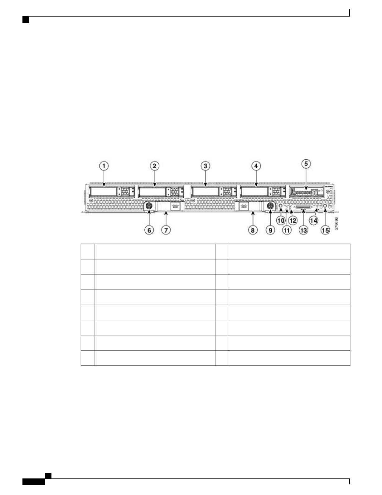
For full service and installation instructions, see the Cisco UCS B200 Blade Server Installation and Service
Note. You can install up to eight UCS B200 M1 or M2 Blade Servers to a chassis.
Figure 1: Cisco UCS B200 M1 and M2
1
numbers
Cisco UCS 5108 Server Chassis Installation Guide
OL-20035-05 5
Network link status LED7Paper tab for server name or serial
Blade health LED8Blade ejector handle2
Page 18

Blade Servers
LEDs
Overview
Console connector9Ejector captive screw3
Reset button access10Hard drive bay 14
Beaconing LED and button11Hard drive bay 25
Power button and LED6
The LED indicators indicate whether the blade server is in active or standby mode, the status of the network
link, the over all health of the blade server, and whether the server is set to give a flashing blue beaconing
indication. See Interpreting LEDs, on page 25 for details.
The removable hard disks also have LEDs indicating hard disk access activity and hard disk health.
Buttons
Connectors
The Reset button is just inside the chassis and must be pressed using the tip of a paper clip or a similar item.
Hold the button down for five seconds and then release it to restart the server if other methods of restarting
are not working.
The beaconing function for an individual server may get turned on or off by pressing the combination button
and LED. See Interpreting LEDs, on page 25 for details.
The power button and LED allows you to manually take a server temporarily out of service but leave it in a
state where it can be restarted quickly.
A console port gives a direct connection to a blade server to allow operating system installation and other
management tasks to be done directly rather than remotely. The port uses the KVM dongle device included
in the chassis accessory kit. See KVM Cable, on page 69 for more information.
Cisco UCS 5108 Server Chassis Installation Guide
6 OL-20035-05
Page 19
Overview
Cisco UCS B200 M3 Blade Servers
For full service and installation instructions, see the Cisco UCS B200 M3 Blade Server Installation and Service
Note. You can install up to eight UCS B200 M3 Blade Servers to a chassis.
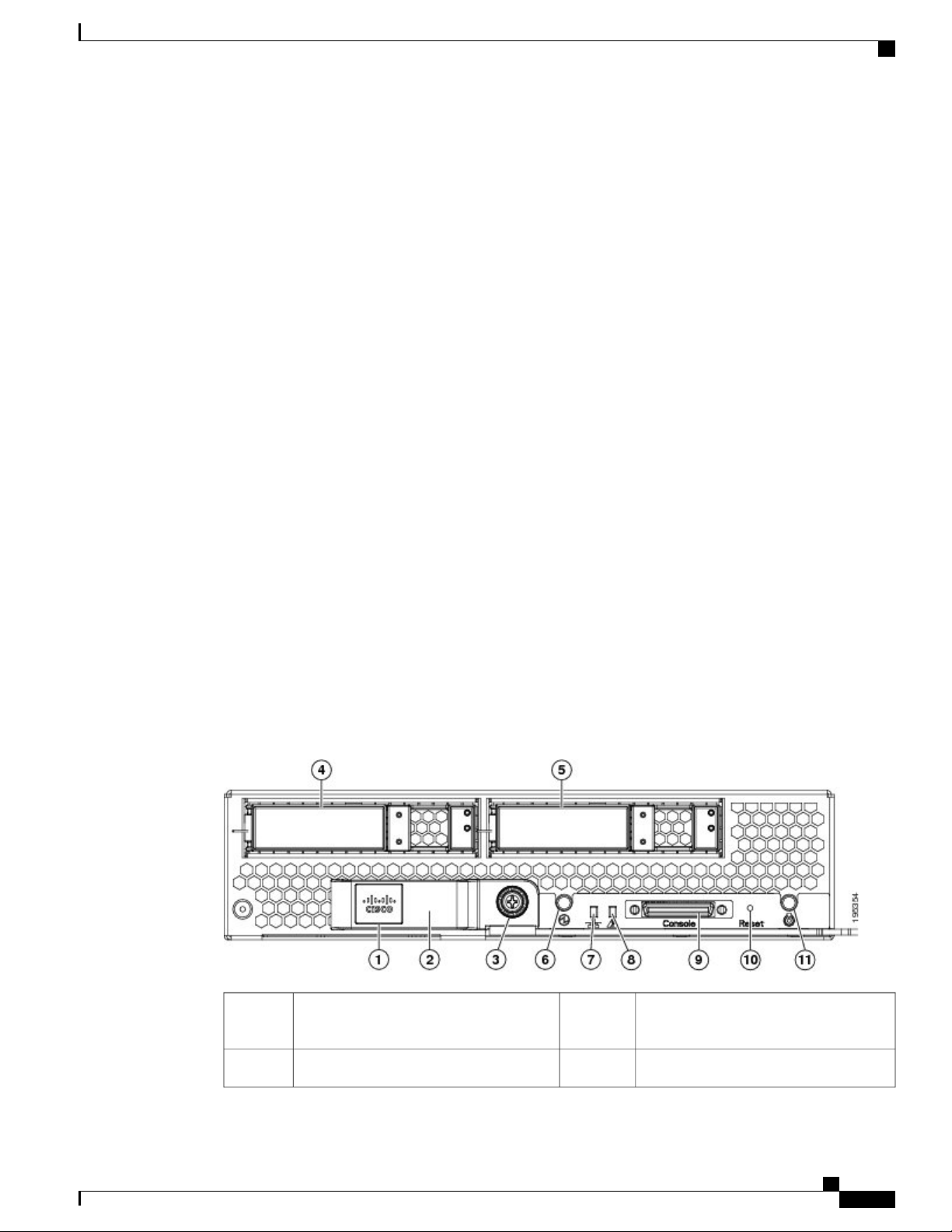
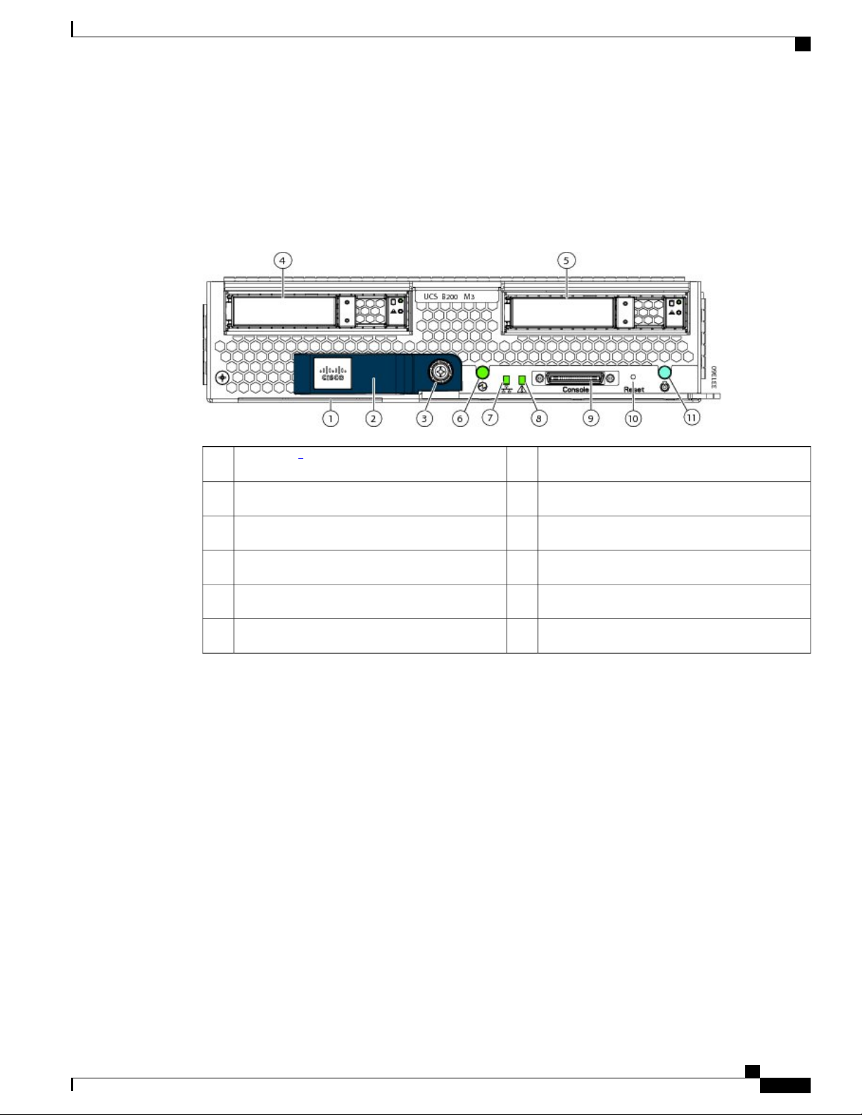
Figure 2: Cisco UCS B200 M3
Blade Servers
1
1
Network link status LED7Asset Tag
Blade health LED8Blade ejector handle2
Console connector9Ejector captive screw3
Reset button access10Hard drive bay 14
Beaconing LED and button11Hard drive bay 25
Power button and LED6
1
Each server has a blank plastic tag that pulls out of the front panel which is provided so that you can add your own asset tracking label without interfering with
the intended air flow.
LEDs
The LED indicators indicate whether the blade server is in active or standby mode, the status of the network
link, the over all health of the blade server, and whether the server is set to give a flashing blue beaconing
indication. See Interpreting LEDs, on page 25 for details.
The removable hard disks also have LEDs indicating hard disk access activity and hard disk health.
Buttons
The Reset button is just inside the chassis and must be pressed using the tip of a paper clip or a similar item.
Hold the button down for five seconds and then release it to restart the server if other methods of restarting
are not working.
The beaconing function for an individual server may get turned on or off by pressing the combination button
and LED. See Interpreting LEDs, on page 25 for details.
Cisco UCS 5108 Server Chassis Installation Guide
OL-20035-05 7
Page 20
Blade Servers
The power button and LED allows you to manually take a server temporarily out of service but leave it in a
state where it can be restarted quickly.
Connectors
A console port gives a direct connection to a blade server to allow operating system installation and other
management tasks to be done directly rather than remotely. The port uses the KVM dongle device included
in the chassis accessory kit. See KVM Cable, on page 69 for more information.
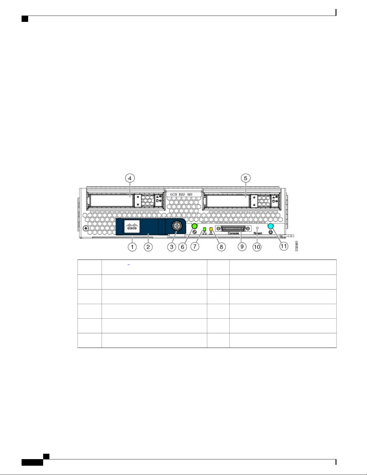
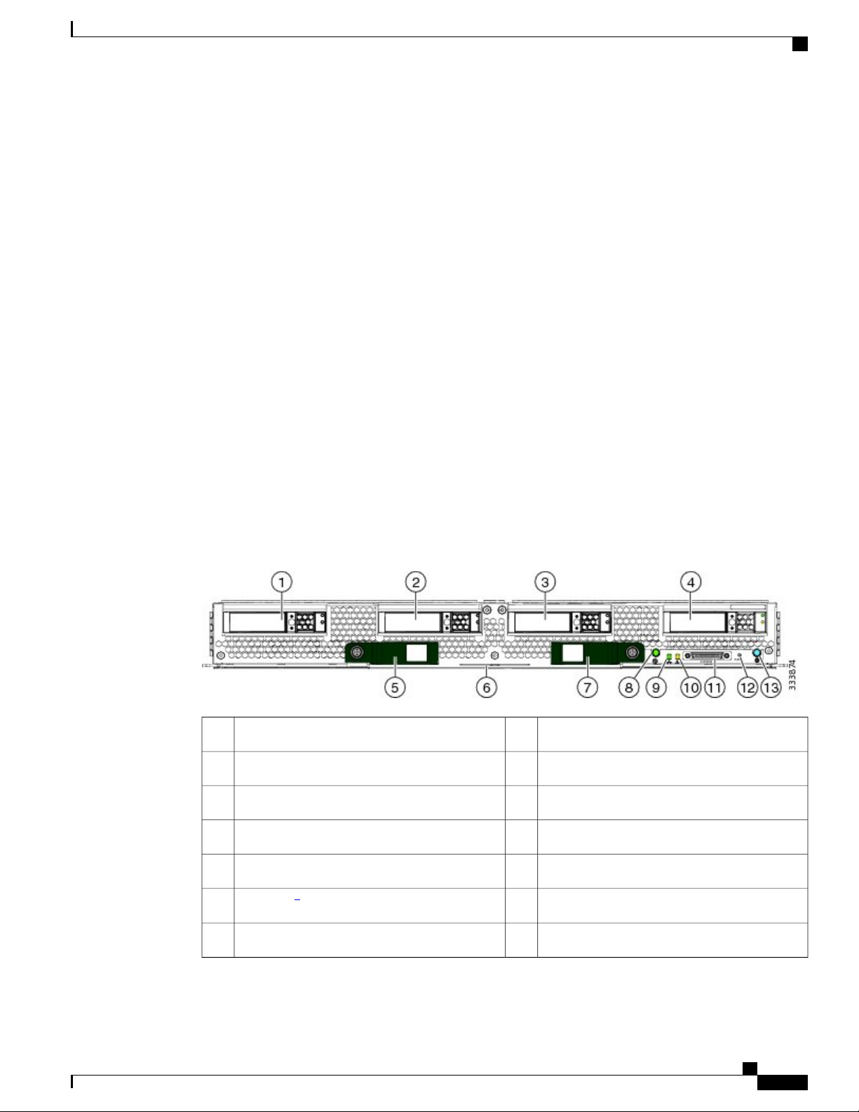
Cisco UCS B22 M3 Blade Servers
For full service and installation instructions, see the Cisco UCS B22 Blade Server Installation and Service
Note. You can install up to eight UCS B22 M3 Blade Servers to a chassis.
Figure 3: Cisco UCS B22 M3
Overview
1
2
Network link status LED7Asset tag
Blade health LED8Blade ejector handle2
Console connector9Ejector captive screw3
Reset button access10Hard drive bay 14
Beaconing LED and button11Hard drive bay 25
Power button and LED6
2
Each server has a blank plastic asset tag that pulls out of the front panel, provided so you can add your own asset tracking label without interfering with the
intended air flow.
LEDs
The LED indicators indicate whether the blade server is in active or standby mode, the status of the network
link, the over all health of the blade server, and whether the server is set to give a flashing blue beaconing
indication. See Interpreting LEDs, on page 25 for details.
Cisco UCS 5108 Server Chassis Installation Guide
8 OL-20035-05
Page 21
Overview
Buttons
Connectors
Blade Servers
The removable hard disks also have LEDs indicating hard disk access activity and hard disk health.
The Reset button is just inside the chassis and must be pressed using the tip of a paper clip or a similar item.
Hold the button down for five seconds and then release it to restart the server if other methods of restarting
are not working.
The beaconing function for an individual server may get turned on or off by pressing the combination button
and LED. See Interpreting LEDs, on page 25 for details.
The power button and LED allows you to manually take a server temporarily out of service but leave it in a
state where it can be restarted quickly.
A console port gives a direct connection to a blade server to allow operating system installation and other
management tasks to be done directly rather than remotely. The port uses the KVM dongle device included
in the chassis accessory kit. See KVM Cable, on page 69 for more information.
Cisco UCS B230 Blade Servers
For full service and installation instructions, see the Cisco UCS B230 Blade Server Installation and Service
Note. You can install up to eight UCS B230 Blade Servers to a chassis.
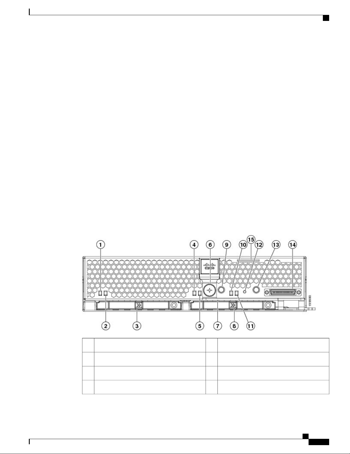
Figure 4: Cisco UCS B230 (N20-B6730) Front Panel
Beaconing LED and button9SSD 1 Activity LED1
System Activity LED10SSD 1 Fault/Locate LED2
Blade health LED11SSD sled in Bay 13
Reset button access12SSD 2 Activity4
Cisco UCS 5108 Server Chassis Installation Guide
OL-20035-05 9
Page 22

Blade Servers
LEDs
Overview
Power button and LED13SSD 2 Fault LED5
Console connector14Ejector lever captive screw6
Asset tag15Ejector lever7
SSD sled in Bay 18
The LED indicators indicate whether the blade server is in active or standby mode, the status of the network
link, the over all health of the blade server, and whether the server is set to give a flashing blue beaconing
indication. See Interpreting LEDs, on page 25 for details.
The removable hard disks also have LEDs indicating hard disk access activity and hard disk health.
Buttons
Connectors
The Reset button is just inside the chassis and must be pressed using the tip of a paper clip or a similar item.
Hold the button down for five seconds and then release it to restart the server if other methods of restarting
are not working.
The beaconing function for an individual server may get turned on or off by pressing the combination button
and LED. See Interpreting LEDs, on page 25 for details.
The power button and LED allows you to manually take a server temporarily out of service but leave it in a
state where it can be restarted quickly.
A console port gives a direct connection to a blade server to allow operating system installation and other
management tasks to be done directly rather than remotely. The port uses the KVM dongle device included
in the chassis accessory kit. See KVM Cable, on page 69 for more information.
Cisco UCS 5108 Server Chassis Installation Guide
10 OL-20035-05
Page 23
Overview
Cisco UCS B250 Blade Servers
For full service and installation instructions, see the Cisco UCS B250 Blade Server Installation and Service
Note.
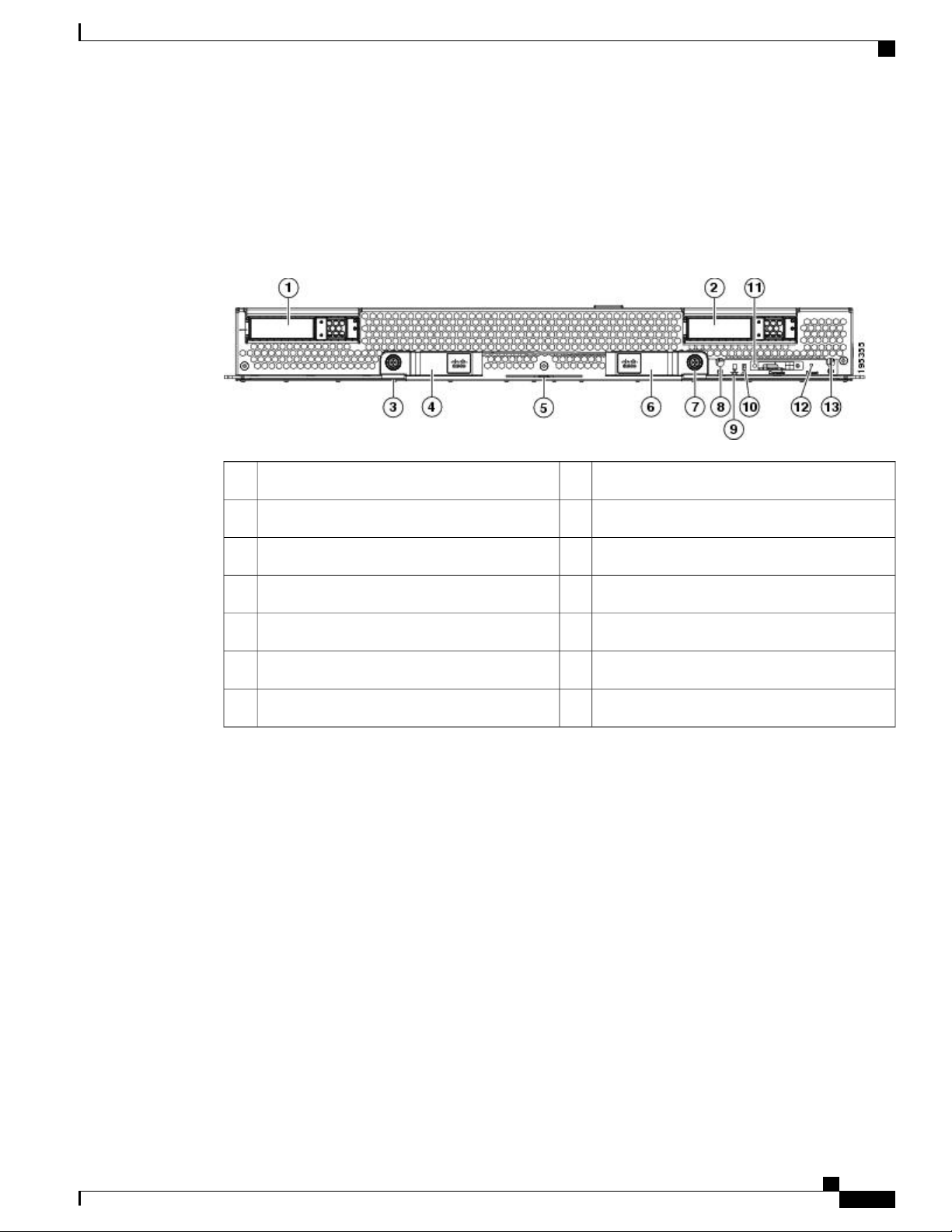
Figure 5: Cisco UCS B250
Blade Servers
Power button and LED8Hard drive bay 11
LEDs
Buttons
Network link status LED9Hard drive bay 22
Blade health LED10Left ejector captive screw3
Console connector11Left blade ejector handle4
Reset button access12Paper tab for server name or serial numbers5
Beaconing LED and button13Right blade ejector handle6
Right ejector captive screw7
The LED indicators indicate whether the blade server is in active or standby mode, the status of the network
link, the over all health of the blade server, and whether the server is set to give a flashing blue beaconing
indication. See Interpreting LEDs, on page 25 for details.
The removable hard disks also have LEDs indicating hard disk access activity and hard disk health.
The Reset button is just inside the chassis and must be pressed using the tip of a paper clip or a similar item.
Hold the button down for five seconds and then release it to restart the server if other methods of restarting
are not working.
The beaconing function for an individual server may get turned on or off by pressing the combination button
and LED. See Interpreting LEDs, on page 25 for details.
The power button and LED allows you to manually take a server temporarily out of service but leave it in a
state where it can be restarted quickly.
Cisco UCS 5108 Server Chassis Installation Guide
OL-20035-05 11
Page 24
Blade Servers
Connectors
A console port gives a direct connection to a blade server to allow operating system installation and other
management tasks to be done directly rather than remotely. The port uses the KVM dongle device included
in the chassis accessory kit. See KVM Cable, on page 69 for more information.
Cisco UCS B440 Blade Servers
For full service and installation instructions, see the Cisco UCS B440 High Performance Blade Server
Installation and Service Note.
Figure 6: Cisco UCS B440
Overview
LEDs
Right ejector thumbscrew9Hard drive bay 11
Power button and LED10Hard drive bay 22
Network link status LED11Hard drive bay 33
Blade health LED12Hard drive bay 44
Local console connection13RAID battery backup module (BBU)5
Reset button access14Left ejector thumbscrew6
Locate button and LED15Left ejector handle7
Right ejector handle8
The LED indicators indicate whether the blade server is in active or standby mode, the status of the network
link, the over all health of the blade server, and whether the server is set to give a flashing blue beaconing
indication. See Interpreting LEDs, on page 25 for details.
The removable hard disks also have LEDs indicating hard disk access activity and hard disk health.
Cisco UCS 5108 Server Chassis Installation Guide
12 OL-20035-05
Page 25
Overview
Buttons
Connectors
Cisco UCS B420 M3 High Performance Blade Server
The Reset button is just inside the chassis and must be pressed using the tip of a paper clip or a similar item.
Hold the button down for five seconds and then release it to restart the server if other methods of restarting
are not working.
The beaconing function for an individual server may get turned on or off by pressing the combination button
and LED. See Interpreting LEDs, on page 25 for details.
The power button and LED allows you to manually take a server temporarily out of service but leave it in a
state where it can be restarted quickly.
A console port gives a direct connection to a blade server to allow operating system installation and other
management tasks to be done directly rather than remotely. The port uses the KVM dongle device included
in the chassis accessory kit. See KVM Cable, on page 69 for more information.
Cisco UCS B420 M3 High Performance Blade Server
For full service and installation instructions, see the Cisco UCS B420 M3 High Performance Blade Server
Installation and Service Note. You can install up to four UCS B420 M3 High Performance Blade Servers to
a chassis.
Figure 7: Cisco UCS B420 M3
Power button and LED8Hard drive bay 11
Network link status LED9Hard drive bay 22
Blade health LED10Hard drive bay 33
Console connector11Hard drive bay 44
Reset button access12Left ejector handle5
6
3
Beaconing LED and button13Asset tag
Right ejector handle7
Cisco UCS 5108 Server Chassis Installation Guide
OL-20035-05 13
Page 26

Overview
Adapter Cards
3
Each server has a blank plastic asset tag that pulls out of the front panel, provided so you can add your own asset tracking label without interfering with the
intended air flow.
LEDs
The LED indicators indicate whether the blade server is in active or standby mode, the status of the network
link, the over all health of the blade server, and whether the server is set to give a flashing blue beaconing
indication. See Interpreting LEDs, on page 25 for details.
The removable hard disks also have LEDs indicating hard disk access activity and hard disk health.
Buttons
The Reset button is just inside the chassis and must be pressed using the tip of a paper clip or a similar item.
Hold the button down for five seconds and then release it to restart the server if other methods of restarting
are not working.
The beaconing function for an individual server may get turned on or off by pressing the combination button
and LED. See Interpreting LEDs, on page 25 for details.
The power button and LED allows you to manually take a server temporarily out of service but leave it in a
state where it can be restarted quickly.
Connectors
A console port gives a direct connection to a blade server to allow operating system installation and other
management tasks to be done directly rather than remotely. The port uses the KVM dongle device included
in the chassis accessory kit. See KVM Cable, on page 69 for more information.
Adapter Cards
Depending on the model of server in question, one to three adapter cards will reside in each blade server,
providing failover connectivity to each FEX in the chassis. The following models are available, and others
are released on an ongoing basis:
Cisco UCS Virtual Interface Card 1280
The Cisco UCS Virtual Interface Card 1280 (UCS-VIC-M82-8P) is an eight-port 10 Gigabit Ethernet, Fibre
Channel over Ethernet (FCoE)-capable mezzanine card designed exclusively for Cisco UCS B-Series Blade
Servers. The card enables a policy-based, stateless, agile server infrastructure that can present up to 256 PCIe
standards-compliant interfaces to the host that can be dynamically configured as either network interface cards
(NICs) or host bus adapters (HBAs). In addition, the Cisco UCS Virtual Interface Card 1280 supports Cisco
Virtual Machine Fabric Extender (VM-FEX) technology, which extends the Cisco UCS Fabric Interconnect
ports to virtual machines, simplifying server virtualization deployment.
Cisco UCS M81KR Virtual Interface Card
The Cisco UCS M81KR Virtual Interface Card is a virtualization-optimized Fibre Channel over Ethernet
(FCoE) adapter card. The virtual interface card is a dual-port 10 Gigabit Ethernet adapter card that supports
Cisco UCS 5108 Server Chassis Installation Guide
14 OL-20035-05
Page 27

Overview
Adapter Cards
up to 128 Peripheral Component Interconnect Express (PCIe) standards-compliant virtual interfaces that can
be dynamically configured so that both their interface type (network interface card [NIC] or host bus adapter
[HBA]) and identity (MAC address and worldwide name [WWNN]) are established using just-in-time
provisioning. In addition, the Cisco UCS M81KR supports network interface virtualization and Cisco VN-Link
technology.
The Cisco UCS M81KR is designed for both traditional operating system and virtualization environments. It
is optimized for virtualized environments, for organizations that seek increased mobility in their physical
environments, and for data centers that want reduced TCO through NIC, HBA, cabling, and switch reduction.
The Cisco UCS M81KR presents up to 128 virtual interfaces to the operating system on a given blade. The
128 virtual interfaces can be dynamically configured by Cisco UCS Manager as either Fibre Channel or
Ethernet devices. Deployment of applications using multiple Ethernet and Fibre Channel interfaces is no
longer constrained by the available physical adapters. To an operating system or a hypervisor running on a
Cisco UCS B-Series Blade Server, the virtual interfaces appear as regular PCIe devices.
The Cisco UCS M81KR has built-in architectural support enabling the virtual machine to directly access the
adapter. I/O bottlenecks and memory performance can be improved by providing virtual machines direct
access to hardware I/O devices, eliminating the overhead of embedded software switches.
The Cisco UCS M81KR also brings adapter consolidation to physical environments. The adapter can be
defined as multiple different NICs and HBAs. For example, one adapter card can replace two quad-port NICs
and two single-port HBAs, resulting in fewer NICs, HBAs, switches, and cables.
Cisco UCS 82598KR-CI 10 Gigabit Ethernet Adapter
The Cisco UCS 82598KR-CI 10 Gigabit Ethernet adapter is based on the Intel 82598 10 Gigabit Ethernet
controller, which is designed for efficient high-performance Ethernet transport. It provides a solution for data
center environments that need low-latency 10 Gigabit Ethernet transport capability, and a dual-port connection
to the midplane of the blade server chassis.
The Cisco UCS 82598KR-CI supports Intel Input/Output Acceleration Technology (I/OAT) as well as virtual
queues for I/O virtualization. The adapter is energy efficient and can also help reduce CPU utilization by
providing large segment offload (LSO) and TCP segmentation offload (TSO). The Cisco UCS 82598KR-CI
uses Intel Virtual Machine Device Queue (VMDq) technology for the efficient routing of packets to the
appropriate virtual machine.
Cisco UCS M71KR-E Emulex Converged Network Adapter
The Cisco UCS M71KR-E Emulex Converged Network Adapter (CNA) is an Emulex-based Fibre Channel
over Ethernet (FCoE) adapter card that provides connectivity for Cisco UCS B-Series Blade Servers in the
Cisco Unified Computing System.
Designed specifically for the Cisco UCS blades, the adapter provides a dual-port connection to the midplane
of the blade server chassis. The Cisco UCS M71KR-E uses an Intel 82598 10 Gigabit Ethernet controller for
network traffic and an Emulex 4-Gbps Fibre Channel controller for Fibre Channel traffic all on the same
adapter card. The Cisco UCS M71KR-E presents two discrete Fibre Channel host bus adapter (HBA) ports
and two Ethernet network ports to the operating system.
The Cisco UCS M71KR-E provides both 10 Gigabit Ethernet and 4-Gbps Fibre Channel functions using
drivers from Emulex, providing:
Compatibility with current Emulex adapter-based SAN environments and drivers
•
Cisco UCS 5108 Server Chassis Installation Guide
OL-20035-05 15
Page 28

Adapter Cards
Consolidation of LAN and SAN traffic over the same adapter card and fabric, reducing the overall
•
number of network interface cards (NICs), HBAs, cables, and switches
Integrated management with Cisco UCS Manager
•
Cisco UCS M71KR-Q QLogic Converged Network Adapter
The Cisco UCS M71KR-Q QLogic Converged Network Adapter (CNA) is a QLogic-based Fibre Channel
over Ethernet (FCoE) adapter card that provides connectivity for Cisco UCS B-Series Blade Servers in the
Cisco Unified Computing System.
Designed specifically for the Cisco UCS blades, the adapter provides a dual-port connection to the midplane
of the blade server chassis. The Cisco UCS M71KR-Q uses an Intel 82598 10 Gigabit Ethernet controller for
network traffic and a QLogic 4-Gbps Fibre Channel controller for Fibre Channel traffic, all on the same adapter
card. The Cisco UCS M71KR-Q presents two discrete Fibre Channel host bus adapter (HBA) ports and two
Ethernet network ports to the operating system.
The Cisco UCS M71KR-Q provides both 10 Gigabit Ethernet and 4-Gbps Fibre Channel functions using
drivers from QLogic, providing:
Overview
Compatibility with current QLogic adapter-based SAN environments and drivers
•
Consolidation of LAN and SAN traffic over the same adapter card and fabric, reducing the overall
•
number of network interface cards (NICs), HBAs, cables, and switches
Integrated management with Cisco UCS Manager
•
Cisco UCS 5108 Server Chassis Installation Guide
16 OL-20035-05
Page 29
4
4
1
2
3
237201
Overview
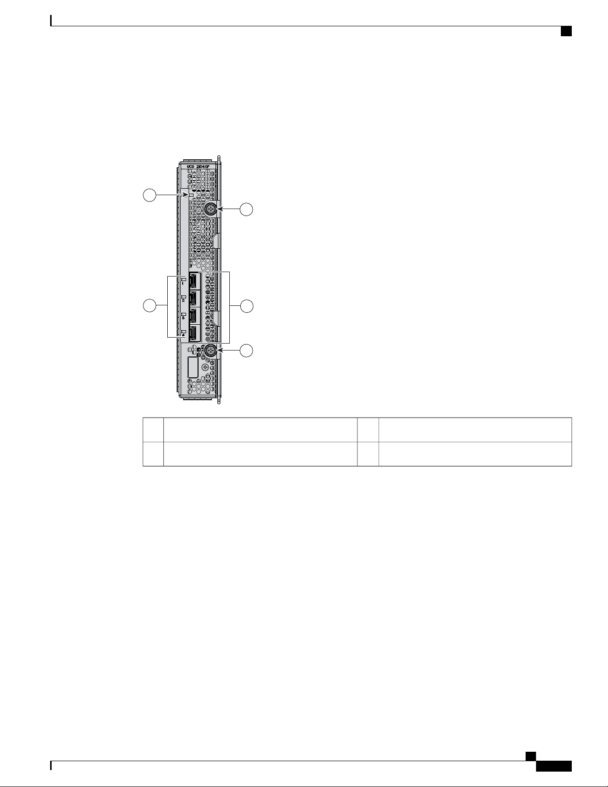
Cisco UCS 2104XP FEXes
Figure 8: Cisco UCS 2104 IO Module
Cisco UCS 2104XP FEXes
Connection ports (to the fabric interconnect)3Fabric extender status indicator LED1
Captive screws for the insertion latches4Link status indicator LEDs2
Cisco UCS 2100 Series FEXes bring the unified fabric into the blade server enclosure, providing 10 Gigabit
Ethernet connections between blade servers and the fabric interconnect, simplifying diagnostics, cabling, and
management.
The Cisco UCS 2104 (N20-I6584) extends the I/O fabric between the fabric interconnects and the Cisco UCS
5100 Series Blade Server Chassis, enabling a lossless and deterministic Fibre Channel over Ethernet (FCoE)
fabric to connect all blades and chassis together. Because the FEX is similar to a distributed line card, it does
not do any switching and is managed as an extension of the fabric interconnects. This approach removes
switching from the chassis, reducing overall infrastructure complexity and enabling the Cisco Unified
Computing System to scale to many chassis without multiplying the number of switches needed, reducing
TCO and allowing all chassis to be managed as a single, highly available management domain.
The Cisco 2100 Series also manages the chassis environment (the power supply and fans as well as the blades)
in conjunction with the fabric interconnect. Therefore, separate chassis management modules are not required.
Cisco UCS 2100 Series FEXes fit into the back of the Cisco UCS 5100 Series chassis. Each Cisco UCS 5100
Series chassis can support up to two FEXes, enabling increased capacity as well as redundancy.
Cisco UCS 5108 Server Chassis Installation Guide
OL-20035-05 17
Page 30

1
2
4
4
3
237200
Cisco UCS 2200 Series FEXes
LEDs
There are port activity LEDs and an LED that indicates connectivity to the servers in the chassis.
Buttons
No buttons are on the FEX.
Connectors
I/O ports support SFP+ 10 Gb Ethernet connections. There is also a console connection for use by Cisco
diagnostic technicians. It is not intended for customer use.
Cisco UCS 2200 Series FEXes
Overview
Figure 9: Cisco UCS 2208 FEX (UCS-IOM-2208XP)
Connection ports (to the fabric interconnect)3Fabric extender status indicator LED1
Captive screws for the insertion latches4Link status indicator LEDs2
18 OL-20035-05
Cisco UCS 5108 Server Chassis Installation Guide
Page 31

4
4
1
2
3
237201
Overview
Cisco UCS 2200 Series FEXes
Figure 10: Cisco UCS 2204XP FEX
Connection ports (to the fabric interconnect)3Fabric extender status indicator LED1
Captive screws for the insertion latches4Link status indicator LEDs2
Cisco UCS 2200 Series FEXes bring the unified fabric into the blade server enclosure, providing 10 Gigabit
Ethernet connections between blade servers and the fabric interconnect, simplifying diagnostics, cabling, and
management.
The Cisco UCS 2200 Series extends the I/O fabric between the fabric interconnects and the Cisco UCS 5100
Series Blade Server Chassis, enabling a lossless and deterministic Fibre Channel over Ethernet (FCoE) fabric
to connect all blades and chassis together. Because the FEX is similar to a distributed line card, it does not
do any switching and is managed as an extension of the fabric interconnects. This approach removes switching
from the chassis, reducing overall infrastructure complexity and enabling the Cisco Unified Computing System
to scale to many chassis without multiplying the number of switches needed, reducing TCO and allowing all
chassis to be managed as a single, highly available management domain.
The Cisco 2200 Series also manages the chassis environment (the power supply and fans as well as the blades)
in conjunction with the fabric interconnect. Therefore, separate chassis management modules are not required.
Cisco UCS 2200 Series FEXes fit into the back of the Cisco UCS 5100 Series chassis. Each Cisco UCS 5100
Series chassis can support up to two FEXes, enabling increased capacity as well as redundancy.
Cisco UCS 5108 Server Chassis Installation Guide
OL-20035-05 19
Page 32

Power Distribution Unit (PDU)
LEDs
There are port activity LEDs and an LED that indicates connectivity to the servers in the chassis.
Buttons
No buttons are on the FEX.
Connectors
I/O ports support SFP+ 10 Gb Ethernet connections. There is also a console connection for use by Cisco
diagnostic technicians. It is not intended for customer use.
Power Distribution Unit (PDU)
The AC PDU (N01-UAC1) provides load balancing between the installed power supplies, as well as distributing
power to the other chassis components. DC versions of the chassis use a different PDU with appropriate
connectors. The PDU is not field-serviceable, and converting an AC chassis to a DC chassis by swapping the
PDU is not supported, as the PDU is not separately orderable.
Overview
LEDs
Buttons
Connectors
No LEDs are on the PDU.
No buttons are on the PDU.
The AC version of the PDU has four power connectors rated for 15.5 A, 200-240V @ 50-60 Hz. Only use
Cisco approved power cords, different power cords are available for many countries and applications. See for
more information about the supported power cords. See Supported AC Power Cords and Plugs, on page 74
for more information.
The DC version of the PDU has eight dual-post lug power connections, four positive and four negative. A
single dual-post lug grounding connection is also provided.
Cisco UCS 5108 Server Chassis Installation Guide
20 OL-20035-05
Page 33

Overview
Fan Modules
The chassis can accept up to eight fan modules (N20-FAN5). A chassis must have filler plates in place if no
fan will be installed in a slot for an extended period.
LEDs
There is one LED indication of the fan module’s operational state. See Interpreting LEDs, on page 25 for
details.
Buttons and Connectors
No buttons or connectors are on a fan module.
Power Supplies
Fan Modules
Different power supplies are available to work with the AC (N20-PAC5-2500W) or DC
(UCSB-PSU-2500DC48) versions of the chassis. To determine the number of power supplies needed for a
given configuration, use the Cisco UCS Power Calculator tool.
LEDs
Two LEDs indicate power connection presence, power supply operation, and fault states. See Interpreting
LEDs, on page 25 for details.
Buttons
There are no buttons on a power supply.
Connectors
The power connections are at the rear of the chassis on the PDU, with different types for AC or DC input.
Four single-phase, hot-swappable power supplies are accessible from the front of the chassis. These power
supplies can be configured to support non-redundant, N+1 redundant, and grid-redundant configurations.
Power Supply Redundancy
Power supply redundancy functions identically for AC and DC configured systems. When considering power
supply redundancy you need to take several things into consideration:
Power supplies are all single phase and have a single input for connectivity to customer power source
•
(a rack PDU such as the Cisco RP Series PDU or equivalent).
The number of power supplies required to power a chassis varies depending on the following factors:
•
Cisco UCS 5108 Server Chassis Installation Guide
OL-20035-05 21
Page 34

Power Supplies
To configure redundancy, see the Configuration Guide for the version of Cisco UCS Central that you are
using. The configuration guides are available at the following URL: http://www.cisco.com/en/US/products/
ps12502/products_installation_and_configuration_guides_list.html.
Non-redundant Mode
In a non-redundant or combined mode, all installed power supplies are turned on and balance the load evenly.
Smaller configurations (requiring less than 2500 W) can be powered by a single power supply when the system
is using Cisco UCS Release 1.3(1) or earlier releases. However, a single power supply cannot provide
redundancy and if either the power input or power supply fail, the system immediately shuts down. More
common configurations require two or more power supplies (if requirements are between 2500 and 5000 W
peak) in non-redundant mode.
When using Cisco UCS Release 1.4(1) and later releases, the chassis requires a minimum of 2 power supplies.
Overview
The total "Maximum Draw" required to power all the components configured within that
◦
chassis—such as I/O modules, fans, blade servers (CPU and memory configuration of the blade
servers).
The Desired Power Redundancy for the chassis. The supported power configurations are
◦
non-redundant, N+1 redundancy (or any requirement greater than N+1), and grid redundancy.
Note
N+1 Redundancy
In a non-redundant system, power supplies can be in any slot. Installing less than the required number of
power supplies results in undesired behavior such as server blade shutdown. Installing more than the
required amount of power supplies may result in lower power supply efficiency. At most, this mode will
require two power supplies.
The N+1 redundancy configuration implies that the chassis contains a total number of power supplies to satisfy
non-redundancy, plus one additional power supply for redundancy. All the power supplies that are participating
in N+1 redundancy are turned on and equally share the power load for the chassis. If any additional power
supplies are installed, Cisco UCS Manager recognizes these “unnecessary” power supplies and places them
on standby.
If a power supply should fail, the surviving supplies can provide power to the chassis. In addition, UCS
Manager turns on any "turned-off" power supplies to bring the system back to N+1 status.
To provide N+1 protection, the following number of power supplies is recommended:
Three power supplies are recommended if the power configuration for that chassis requires greater than
•
2500 W or if using UCS Release 1.4(1) and later releases
Two power supplies are sufficient if the power configuration for that chassis requires less than 2500 W
•
or the system is using UCS Release 1.3(1) or earlier releases
Adding an additional power supply to either of these configurations will provide an extra level of protection.
Cisco UCS Manager turns on the extra power supply in the event of a failure and restores N+1 protection.
Cisco UCS 5108 Server Chassis Installation Guide
22 OL-20035-05
Page 35

PS 1
PS 2
PS 3
PS 4
Server Slot 1
Server Slot 2
Server Slot 3
Server Slot 5
Server Slot 7
Server Slot 4
Server Slot 6
Server Slot 8
Front
Fan 1
Fan 2
I/O Module Slot 1
I/O Module Slot 2
Connector
PS 4
Connector
PS 3
Connector
PS 2
Connector
PS 1
Fan 6
Fan 5
Fan 4
Fan 3
Fan 8
Fan 7
Rear
279770
Overview
Grid Redundancy
LEDs
An n+1 redundant system has either two or three power supplies, which may be in any slot.Note
The grid redundant configuration is sometimes used when you have two power sources to power a chassis or
you require greater than N+1 redundancy. If one source fails (which causes a loss of power to one or two
power supplies), the surviving power supplies on the other power circuit continue to provide power to the
chassis. A common reason for using grid redundancy is if the rack power distribution is such that power is
provided by two PDUs and you want the grid redundancy protection in the case of a PDU failure.
To provide grid redundant (or greater than N+1) protection, the following number of power supplies is
recommended:
Four power supplies are recommended if the power configuration for that chassis requires greater than
•
2500W or if using Cisco UCS Release 1.4(1) and later releases
Two power supplies are recommended if the power configuration for that chassis requires less than
•
2500W or the system is using Cisco UCS Release 1.3(1) or earlier releases
LEDs
Note
Both grids in a power redundant system should have the same number of power supplies. If your system
is configured for grid redundancy, slots 1 and 2 are assigned to grid 1 and slots 3 and 4 are assigned to
grid 2. If there are only two power supplies (PS) in the a redundant mode chassis, they should be in slots
1 and 3. Slot and cord connection numbering is shown below.
Figure 11: Power Supply Bay and Connector Numbering
LEDs on both the chassis and the modules installed within the chassis identify operational states, both separately
and in combination with other LEDs.
Cisco UCS 5108 Server Chassis Installation Guide
OL-20035-05 23
Page 36

192744
LED Locations
LED Locations
Overview
Figure 12: LEDs on a Cisco UCS 5108 Server Chassis—Front View
Figure 13: LEDs on the Cisco UCS 5108 Server Chassis—Rear View
Cisco UCS 5108 Server Chassis Installation Guide
24 OL-20035-05
Page 37

192743
Overview
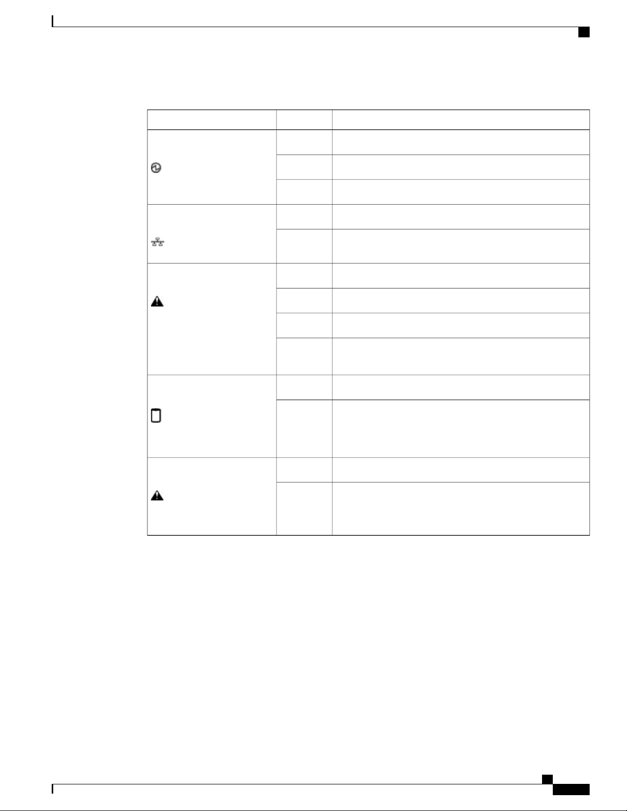
Interpreting LEDs
Interpreting LEDs
Table 2: Chassis, Fan, and Power Supply LEDs
LED and button
Blinking blue 1 Hz
Amber
Blinking amberChassis health
DescriptionColorLED
Beaconing not enabled.OffBeaconing
Beaconing to locate a selected chassis—If the LED
is not blinking, the chassis is not selected. You
can initiate beaconing in UCS Manager or with
the button.
No power.OffChassis connections
No I/O module is installed or the I/O module is
booting.
Normal operation.Green
Indicates a component failure or a major
over-temperature alarm.
Cisco UCS 5108 Server Chassis Installation Guide
OL-20035-05 25
Page 38

Interpreting LEDs
Overview
DescriptionColorLED
Power Supply
Table 3: I/O Module LEDs
OffFan Module
Blinking green
No power to the chassis or the fan module was
removed from the chassis.
Fan module restarting.Amber
Normal operation.Green
The fan module has failed.Blinking amber
No power to the slot.OffOK
Normal operation.Green
AC power is present but the PS is either in
redundancy standby mode or is not fully seated.
Normal operation.OffFail
Over-voltage failure or over-temperature alarm.Amber
DescriptionColorLED
No power.OffBody
Normal operation.Green
Booting or minor temperature alarm.Amber
POST error or other error condition.Blinking amber
Link down.OffPort 1-4
Link up and operationally enabled.Green
Link up and administratively disabled.Amber
POST error or other error condition.Blinking amber
Cisco UCS 5108 Server Chassis Installation Guide
26 OL-20035-05
Page 39
Overview
Interpreting LEDs
Table 4: Blade Server LEDs
DescriptionColorLED
Power off.OffPower
Normal operation.Green
Standby.Amber
None of the network links are up.OffLink
At least one network link is up.Green
Power off.OffHealth
Normal operation.Green
(Disk Drive)
(Disk Drive)
Minor error.Amber
Critical error.Blinking
Amber
Inactive.OffActivity
Outstanding I/O to disk drive.Green
No fault.OffHealth
Some fault.Amber
Cisco UCS 5108 Server Chassis Installation Guide
OL-20035-05 27
Page 40

Interpreting LEDs
Overview
Cisco UCS 5108 Server Chassis Installation Guide
28 OL-20035-05
Page 41

CHAPTER 2
Installation
This chapter contains the following sections:
Installation Notes and Warnings for the Cisco UCS 5108 Server Chassis, page 29
•
Installing the Chassis, page 35
•
Repacking the Chassis, page 51
•
SFP+ Transceivers, page 51
•
Installation Notes and Warnings for the Cisco UCS 5108 Server Chassis
The following notes and warnings apply to all installation tasks:
Note
Warning
Warning
OL-20035-05 29
Before you install, operate, or service the system, see the Regulatory Compliance and Safety Information
for Cisco UCS for important safety information.
IMPORTANT SAFETY INSTRUCTIONS
This warning symbol means danger. You are in a situation that could cause bodily injury. Before you
work on any equipment, be aware of the hazards involved with electrical circuitry and be familiar with
standard practices for preventing accidents. Use the statement number provided at the end of each warning
to locate its translation in the translated safety warnings that accompanied this device. Statement 1071
SAVE THESE INSTRUCTIONS
This unit is intended for installation in restricted access areas. A restricted access area can be accessed
only through the use of a special tool, lock and key, or other means of security. Statement 1017
Cisco UCS 5108 Server Chassis Installation Guide
Page 42

Rack Requirements
Installation
Warning
Only trained and qualified personnel must be allowed to install, replace, or service this equipment.
Statement 1030
Rack Requirements
This section provides the requirements for installing in a standard open rack, assuming an external ambient
air temperature range of 50 to 95°F (10 to 35°C):
Note
Do not use racks that have obstructions. These obstructions could impair access to field-replaceable units
(FRUs).
The Cisco R Series Racks are an ideal choice. If other racks will be used, the rack must be of the following
type:
Standard 19-inch (48.3 cm) four-post EIA rack, a minimum of 39.4 inches (100 cm) deep, with mounting
•
rails that conform to English universal hole spacing per section 1 of ANSI/EIA-310-D-1992.
The mounting holes of the rails in the rack must be square (unless the optional round hole adapter kit is
•
used).
The tool-less rack-mount kit shipped with the chassis is required. The adjustable rack rails shipped with
•
each enclosure extend from 29 inches (73.66 cm) to 35 inches (88.9 cm)
• Front and rear doors—If your server rack includes closing front and rear doors, the doors must have 65
percent open perforated area evenly distributed from top to bottom to permit adequate airflow.
Caution
The rack must also meet the following requirements:
The minimum available vertical rack space per chassis must be six RU (rack units), equal to 10.5 inches
•
(26.7 cm).
Cable Management
To help with cable management, allow additional space in the rack above and below the chassis to make it
easier to route copper cables (plus up to eight copper cables per Cisco UCS 5108 server chassis) through the
rack.
Cable management can be an important factor in preventing overheating issues. In the following figure, the
“before“ illustration shows cables blocking the rear of the chassis, and preventing the fans from exhausting
warm air from the chassis. This situation causes failed DIMMs in the blade servers, and seemingly random
Always use blanking panels to fill all remaining empty front panel U-spaces in the rack.
This arrangement ensures proper airflow. Using a rack without blanking panels results
in improper cooling that can lead to thermal damage.
Cisco UCS 5108 Server Chassis Installation Guide
30 OL-20035-05
Page 43

253898
Before
After
Installation
Airflow Considerations
server shutdowns when internal temperatures exceed specification. Use cable ties and other wiring practices
to keep the rear of the chassis unobstructed as shown in the “after“ illustration.
Figure 14: Cable Management
Airflow Considerations
Airflow through the chassis is from front to back. Air enters the chassis through the blade servers and power
supply grills at the front of the chassis and exits through the fan modules on the back of the chassis. To ensure
proper airflow, follow these guidelines:
Maintain ambient airflow throughout the data center to ensure normal operation.
•
Consider the heat dissipation of all equipment when determining air-conditioning requirements. Do not
•
allow the exhaust of one system to be the intake for another system.
When evaluating airflow requirements, take into consideration that the hot air generated by equipment
•
at the bottom of the rack can be drawn in the intake of the equipment above.
Make sure that the exhaust at the rear of the chassis is unobstructed for at least 24 in. (61 cm). This
•
includes obstruction due to messy cabling practices.
Some blade servers ship with internal shrouds that are placed over the DIMMs and CPUs. They are used
•
to channel airflow to where it is needed the most. If a shroud can be used a given model, it should be
used.
If an enclosed rack is used, the front door must be 65 percent perforated to ensure adequate airflow to
•
the servers.
Cisco UCS 5108 Server Chassis Installation Guide
OL-20035-05 31
Page 44

Moving Server Chassis
Moving Server Chassis
When lifting the chassis, be aware of its weight, and follow these guidelines:
Installation
Caution
Do not try to lift the chassis using the handles on the side. These handles are intended only for moving
and adjusting the chassis position.
• Never lift the chassis alone—Always use two people to lift the chassis. If available, use a scissor jack
or other lifting device designed for installing heavy equipment into data center racks.
Disconnect all power and external cables before lifting the chassis.
•
Remove all FEXes, power supplies, fans, and servers from the chassis before lifting.
•
Ensure that your footing is solid and the weight of the system is evenly distributed between your feet.
•
Lift the system slowly, keeping your back straight. Lift with your legs, not with your back. Bend at the
•
knees, not at the waist.
Do not remove the Power Distribution Unit (PDU) located at the back of the chassis.Caution
Installation Guidelines
When installing the chassis, follow these guidelines:
Plan your site configuration and prepare the site before installing the chassis. See Site Planning and
•
Maintenance Records, on page 79 for the recommended site planning tasks. For details, see the Cisco
UCS Site Preparation Guide.
Record the information listed in Site Planning and Maintenance Records, on page 79 as you install and
•
configure the chassis.
Ensure that there is adequate space around the chassis to allow for servicing the chassis and for airflow.
•
Ensure that the air-conditioning meets the heat dissipation requirements listed in Technical Specifications,
•
on page 69
Ensure that the cabinet or rack meets the requirements listed in Rack Requirements, on page 30.
•
Note
Ensure that the site power meets the power requirements listed in Technical Specifications, on page
•
69. We recommend that you use a UPS to protect the UCS system. Using an unprotected supply exposes
you to a risk of system failure due to input supply voltage variations or failures.
Cisco UCS 5108 Server Chassis Installation Guide
32 OL-20035-05
Jumper power cords are available for use in a rack. See Specifications for the Cisco
UCS 5108 Blade Server Chassis Power Supply Units, on page 72.
Page 45

Installation
Avoid UPS types that use ferroresonant technology. These UPS types can become unstable with systems
such as the Cisco UCS, which can have substantial current draw fluctuations due to fluctuating data
traffic patterns.
Ensure that circuits are sized according to local and national codes. For North America, the power supply
•
requires a 20 A circuit.
To prevent loss of input power, ensure that the total maximum loads on the circuits supplying power to
the chassis are within the current ratings for the wiring and breakers.
Use the following torque values when installing the chassis:
•
Required Equipment
Before you begin the installation, ensure that you have the following items:
Number 1 and number 2 Phillips-head screwdrivers with torque measuring capabilities
•
10-32 screws: 20 in-lb
◦
Required Equipment
Tape measure and level
•
ESD wrist strap or other grounding device
•
Antistatic mat or antistatic foam
•
Unpacking and Inspecting the Chassis
When handling chassis components, wear an ESD strap and handle modules by the carrier edges only.Caution
Keep the shipping container in case the chassis requires shipping in the future.Tip
Note
The chassis is thoroughly inspected before shipment. If any damage occurred during transportation or any
items are missing, contact your customer service representative immediately.
Procedure
Step 1
Step 2
OL-20035-05 33
Remove the chassis from its cardboard container. Save all packaging material.
Compare the shipment to the equipment list provided by your customer service representative and verify that
you have received the following items:
Any printed documentation
•
• Tool-less rack-mount kit (N20-CRMK2=)—mounting rails can be installed in a rack without the use of
tools. The optional round hole adapter kit (N20-CRMK2-RHA=) does require tools.
Cisco UCS 5108 Server Chassis Installation Guide
Page 46
279771
1
2
3
Attaching the Round Hole Adapter Kit to the Rails (Optional)
ESD wrist strap
•
Cables with connectors (including the N20-BKVM=, which is the KVM/local I/O console dongle)
•
Any optional items ordered
•
Installation
Step 3
Verify that all unused blade slots and power supply bays have blank covers.
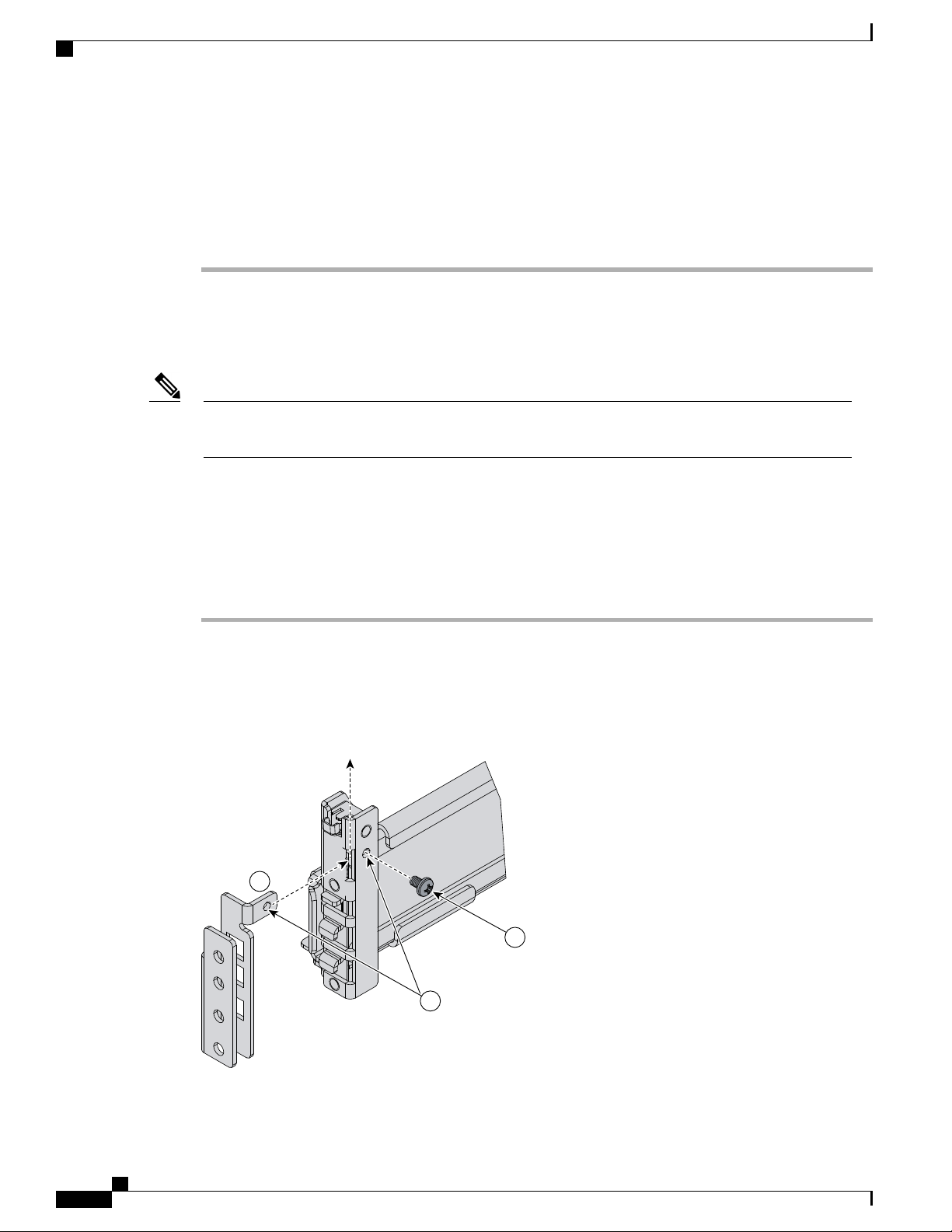
Attaching the Round Hole Adapter Kit to the Rails (Optional)
Note
Step 1
Step 2
Step 3
The chassis tool-less rails are designed for racks that have square mounting holes. You must use the round
hole adapters (N20-CRMK2-RHA=) to install the chassis in racks that have round mounting holes.
This round hole adapter kit allows you to adapt the rail kit (N20-CRMK2=) to install into rack (front and/or
rear) posts that use either threaded or non-threaded round holes. Four adapters in the kit are for adapting the
rail kit to install into rack posts with threaded round holes, and the other four adapters in the kit are for adapting
the rail kit to install into rack posts with non-threaded round holes. You can use a combination of adapters
based on the type of holes in the rack posts. Various sizes and lengths of screws are also included in the kit.
Procedure
Insert the adapter tab into the mounting rail as shown in callout 1.
Slide the adapter up to lock it into position as shown in callout 2.
Secure the adapter into place using the provided pan-head screw as shown in callout 3.
Figure 15: Attaching the Round Hole Adapter (Optional)
Cisco UCS 5108 Server Chassis Installation Guide
34 OL-20035-05
Page 47
Installation
Installing the Chassis
Step 4
Repeat steps 1to 3 for the other three adapters.
Installing the Chassis
This section describes how to install the chassis. This two part process consists of installing the rails into the
rack and then installing the chassis into the rack and on to the rails.
Caution
Caution
Never attempt to lift the chassis by using an installed module’s handle as a grip point. only use the handles
on the sides of the chassis.
If the rack has wheels, ensure that the brakes are engaged, the stabilizing pads are extended, or that the
rack is otherwise stabilized.
Table 5: Contents of the Cisco UCS 5108 Server Chassis Rack-Mount Kit (N20-CRMK2=)
Part DescriptionQuantity
Left tool-less rack mount rail1
Warning
Right tool-less rack mount rail1
10-32 X 0.75 Phillips round washer head screws6
10-32 X 0.125 cage nuts6
Table 6: Contents of the Cisco UCS 5108 Server Round Hole Adapter Kit (N20-CRMK2-RHA=)
Part DescriptionQuantity
Round hole adapters (threaded)4
Round hole adapters (un-threaded)4
Adapter securing screws4
Phillips head screws for securing the rails to the rack16
The plug-socket combination must be accessible at all times, because it serves as the main disconnecting
device. Statement 1019
Cisco UCS 5108 Server Chassis Installation Guide
OL-20035-05 35
Page 48

192517
Sl
i
de-adjust
192731
.250
.625
.625
.500
Installing the Rails
Installing the Rails
Procedure
Installation
Step 1
Step 2
Step 3
Remove the mounting template (Cisco 78-19093-01) from the accessory box. The template is designed to
show you the proper holes within which the rails and cage nuts should be placed. Once the rack holes line up
with the template, you should mark the holes so that their position is known after removing the template.
Adjust the length of the rail by sliding the ends of the rail back and forth until they match the depth of the
rack.
Figure 16: Adjusting the Tool-less Rack Mount Rail
Place the two hooks at each end of the rail into the first two holes at a rack unit boundary.
Figure 17: Hole Spacing for the Tool-less Rails in Relationship to a Rack Unit
Cisco UCS 5108 Server Chassis Installation Guide
36 OL-20035-05
Page 49
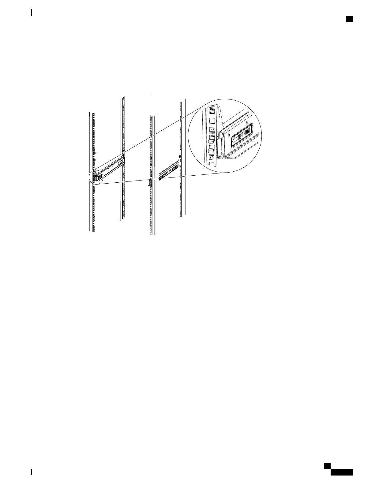
192518
Installation
Installing the Rails
The following figure shows a rail mounted into a rack in the proper position with respect to a rack-unit
boundary. Measurements are in inches between the centers of the holes.
Figure 18: Installing Tool-less Chassis Support Rails into the Rack
Step 4
Step 5
Step 6
Step 7
Press down firmly on the rail until the hooks seat firmly and securely into the holes, and the spring clip latches
into place.
Follow the same procedure to install the other rack rail.
Use a tape measure and level to verify that the rack rails are horizontal and at the same height.
Insert the cage nuts on to the rack in the needed square holes as shown below. When the rails are installed on
a rack unit boundary, the first two cage nuts are installed into the seventh holes above the rails’ horizontal
OL-20035-05 37
Cisco UCS 5108 Server Chassis Installation Guide
Page 50

192824
4
5
7
Lower rack unit
reference boundry
Installing the Rails
Installation
plates. The next two cage nuts are installed into the fifth holes above the first cage nut. Finally, the two cage
nuts are installed into the fourth holes above the second cage nuts.
Figure 19: Placement of Rails and Cage Nuts with Respect to the Rack Unit Boundary
Figure 20: Proper Placement for the Rails and Cage Nuts
Cisco UCS 5108 Server Chassis Installation Guide
38 OL-20035-05
Page 51

.250
.625
.625
.500
.
Left rail
Right rail
Cage nuts
192730
Installation
Installing the Round Hole Adapter Kit
Step 8
Remove all power supplies, fan assemblies, server blades, and fabric extenders to lighten the chassis. Even
with devices removed, the chassis weighs 90 lbs (40.83 kg).
Installing the Round Hole Adapter Kit
Before installing the chassis in a round hole rack, prepare the rails by adding the adapter kit according to the
instructions in Attaching the Round Hole Adapter Kit to the Rails (Optional), on page 34.
Cisco UCS 5108 Server Chassis Installation Guide
OL-20035-05 39
Page 52

279772
Installing the Round Hole Adapter Kit
Procedure
Installation
Step 1
Step 2
Step 3
Step 4
Remove the mounting template (Cisco 78-19093-01) from the accessory box. The template is designed to
show you the proper holes within which the rails and cage nuts should be placed. Once the rack holes line up
with the template, you should mark the holes so that their position is known after removing the template.
Adjust the length of the rail by sliding the ends of the rail back and forth until they match the depth of the
rack.
Place the adapters and rails even with a rack boundary at each end of the rail.
Secure the rail to the rack with the provided pan head screws as shown below.
Figure 21: Attaching the Mounting Brackets to a Round Hole Rack
Cisco UCS 5108 Server Chassis Installation Guide
40 OL-20035-05
Page 53

279774
Installation
Installing the Round Hole Adapter Kit
Step 5
Follow the same procedure to install the other rack rail as shown below.
Figure 22: Round Hole Adapter and Rails Installed in a Rack
Step 6
Step 7
Use a tape measure and level to verify that both rack rails are horizontal and at the same height.
Remove all power supplies, fan assemblies, server blades, and I/O modules to lighten the chassis. Even with
devices removed, the chassis weighs 90 lbs (40.83 kg).
Cisco UCS 5108 Server Chassis Installation Guide
OL-20035-05 41
Page 54

192518
Weight bearing surface.
Chassis should be riding
on this surface.
NON-WEIGHT BEARING SURFACE-
CHASSIS SHOULD NOT BE RIDING
ON THIS SURFACE
Inserting the Chassis into the Rack
Inserting the Chassis into the Rack
Procedure
Installation
Step 1
With the help of another person (or special lifting equipment), lift the chassis and place it on the mounting
rail as shown.
Figure 23: Mounting Rail Weight Distribution (Square Hole Mount Shown)
Caution
The mounting rails may come loose and cause the chassis to fall if the weight is resting on the
wrong surface. Make sure that the bottom of the chassis is resting on the correct rail surface.
42 OL-20035-05
Cisco UCS 5108 Server Chassis Installation Guide
Page 55

192519
Installation
Inserting the Chassis into the Rack
Step 2
Step 3
Slide the chassis into the rack until the front flange is flat against the cage nuts. (Cage nuts are not needed in
round hole racks.)
Using the six Phillips round washer head screws and the cage nuts (used in square hole installations), secure
the chassis by its flanges to the rack as shown.
Figure 24: Securing the Chassis Into the Rack
Step 4
Step 5
Replace all servers, fans, and power supplies back into their respective chassis slots.
To power up the chassis, connect the appropriate AC power cables to the inlet connector corresponding to
each installed power supply, and then connect the other end of the cables to the power source. For a DC
installation, see Connecting a DC Power Supply, on page 44.To determine the number of power supplies
needed for a given configuration, use the Cisco UCS Power Calculator tool.
Cisco UCS 5108 Server Chassis Installation Guide
OL-20035-05 43
Page 56
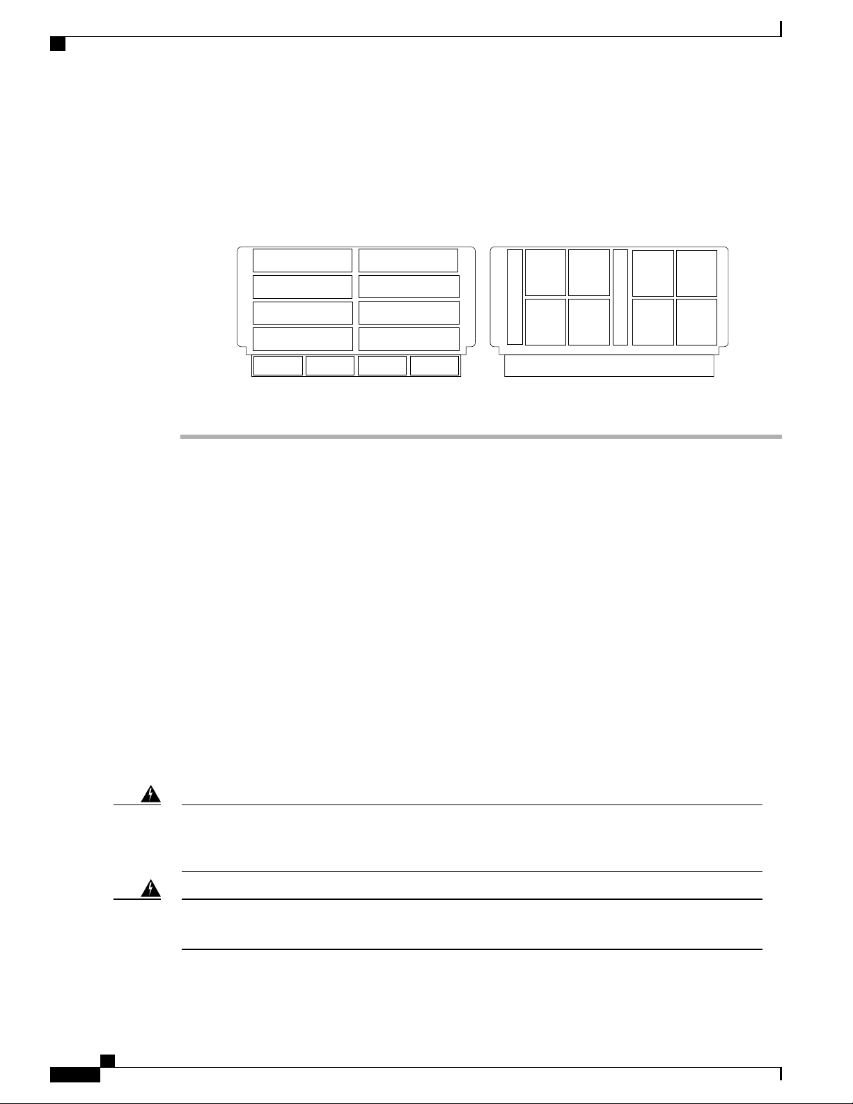
PS 1
PS 2
PS 3
PS 4
Server Slot 1
Server Slot 2
Server Slot 3
Server Slot 5
Server Slot 7
Server Slot 4
Server Slot 6
Server Slot 8
Front
Fan 1
Fan 2
I/O Module Slot 1
I/O Module Slot 2
Connector
PS 4
Connector
PS 3
Connector
PS 2
Connector
PS 1
Fan 6
Fan 5
Fan 4
Fan 3
Fan 8
Fan 7
Rear
279770
Connecting a DC Power Supply
Installation
Note
Both grids in a power redundant system should have the same number of power supplies. If your
system is configured for grid redundancy, slots 1 and 2 are assigned to grid 1 and slots 3 and 4 are
assigned to grid 2. If only two power supplies (PS) are in a redundant- mode chassis, they should be
in slots 1 and 3. Slot and cord connection numbering is shown below.
Figure 25: Power Supply Bay and Connector Numbering
Step 6
Connect the server chassis to the fabric interconnect as described in Proper FEX and Fabric Interconnect Port
Connectivity, on page 48.
Connecting a DC Power Supply
This section describes how to connect power to the rear PDU terminals on the DC version chassis
(UCSB-5108-DC) corresponding to a UCS 5108 DC power supply (UCSB-PSU-2500DC48).
Required Tools
You must have the following tools to perform this procedure:
A Phillips screwdriver
•
A 10-mm wrench or socket
•
Connectors and wire for the DC circuit or circuits
•
DC Power Installation Procedure
Warning
Warning
When stranded wiring is required, use approved wiring terminations, such as closed-loop or spade-type
with upturned lugs. These terminations should be the appropriate size for the wires and should clamp both
the insulation and conductor. Statement 1002
Before performing any of the following procedures, ensure that power is removed from the DC circuit.
Statement 1003
44 OL-20035-05
Cisco UCS 5108 Server Chassis Installation Guide
Page 57

Installation
Connecting a DC Power Supply
Warning
Warning
Warning
Warning
A readily accessible two-poled disconnect device must be incorporated in the fixed wiring. Statement
1022
Use copper conductors only. Statement 1025Warning
This product requires short-circuit (overcurrent) protection, to be provided as part of the building installation.
Install only in accordance with national and local wiring regulations. Statement 1045
When installing or replacing the unit, the ground connection must always be made first and disconnected
last. Statement 1046
Installation of the equipment must comply with local and national electrical codes. Statement 1074Warning
Hazardous voltage or energy may be present on DC power terminals. Always replace cover when terminals
are not in service. Be sure uninsulated conductors are not accessible when cover is in place. Statement
1075
Step 1
Step 2
Step 3
Step 4
Step 5
Step 6
Procedure
Install the DC power supply in the chassis, making note of the bay number, so you are sure to connect the
wiring to the appropriate terminals on the DC PDU at the chassis rear.
Verify that power is off to the DC circuit or circuits on the power supply that you are installing.
Ensure that all site power and grounding requirements have been met.
Remove the plastic cover from the DC terminals by squeezing the flanges at the top and bottom of the cover.
Connect the ground wires to the power supply terminal block, shown as a green wire below. Only one ground
connection is required, though there may be up to four DC connections.
Connect the DC-input wires to the power supply terminal block. The proper wiring sequence is positive to
positive (red wire), and negative to negative (black wire). The figure below shows a connection to terminal
1.
Cisco UCS 5108 Server Chassis Installation Guide
OL-20035-05 45
Page 58

237204
Connecting a DC Power Supply
Installation
Note
The positive and negative wires can be installed pointing either to the right or to the left as long as
the terminal cover is used. The figure below shows them pointed to the right. Panduit LCD4-14A-L
connectors may be used for the supply and return wires, and Panduit LCD4-14AF-L or equivalent
connectors may be used for the 90-degree ground lug wire. Both connections have double lugs with
.25 inch holes measuring .625 inches from center to center.
Figure 26: Connecting DC Power to the Chassis (shows DC PDU only, Chassis is Omitted)
Cisco UCS 5108 Server Chassis Installation Guide
46 OL-20035-05
Page 59

1 3 5 7 9 11 13 15 17 19 21 23 25 27 29 31
26 28 30 3218 20 22 2410 12 14 162 4 6 8
1 3 5 7 9 11 13 15
10 12 14 162 4 6 8
1 2 3 4 5 6
330345
Installation
Cabling Considerations for Fabric Port Channels
Step 7
Replace the terminal cover as shown. This cover should always be in place when power is applied to the
terminals.
Step 8
Step 9
Connect the other end of the power wires to a DC-power input source.
Set the DC disconnect switch in the circuit to ON.
Caution
In a system with multiple power supplies, connect each power supply to a separate DC power
source. In the event of a power source failure, if the second source is still available, it can maintain
system operation.
Step 10
Step 11
Verify power supply operation by checking the power supply's front-panel LEDs. You should see the following:
The LED labeled INPUT OK is green.
•
The LED labeled OUTPUT FAIL is not lit.
•
Check the power supply and system status from the UCS console by entering the show system command or
the show power command, do using the GUI. For more information on these commands, refer to the command
reference for your software.
Cabling Considerations for Fabric Port Channels
When you configure the links between the Cisco UCS 2200 Series FEX and a Cisco UCS 6200 series fabric
interconnect in fabric port channel mode, the available VIF namespace on the adapter varies depending on
where the FEX uplinks are connected to the fabric interconnect ports.
Inside the 6248 fabric interconnect there are six sets of eight contiguous ports, with each set of ports managed
by a single chip. When uplinks are connected such that all of the uplinks from an FEX are connected to a set
of ports managed by a single chip, Cisco UCS Manager maximizes the number of VIFs used in service profiles
deployed on the blades in the chassis. If uplink connections from an IOM are distributed across ports managed
by separate chips, the VIF count is decreased.
Figure 27: Port Groups for Fabric Port Channels
Caution
Adding a second link to a fabric port channel port group is disruptive and will automatically increase the
available amount of VIF namespace from 63 to 118. Adding further links is not disruptive and the VIF
namespace stays at 118.
OL-20035-05 47
Cisco UCS 5108 Server Chassis Installation Guide
Page 60

Proper FEX and Fabric Interconnect Port Connectivity
Installation
Caution
Linking a chassis to two fabric port channel port groups is disruptive and does not affect the VIF namespace
unless it is manually acknowledged. The VIF namespace is then automatically set to the smaller size fabric
port channel port group usage (either 63 or 118 VIFs) of the two groups.
For high availability cluster mode applications, symmetric cabling configurations are strongly recommended.
If the cabling is asymmetric, the maximum number of VIFs available is the smaller of the two cabling
configurations.
For more information on the maximum number of VIFs for your Cisco UCS environment, see the configuration
limits document for your hardware and software configuration.
Proper FEX and Fabric Interconnect Port Connectivity
Note
The following illustrations are for example only; you do not need to skip available ports to provide future
expansion room. See the UCS Manager configuration guide for FI port configuration considerations and
limitations.
Observe the following guidelines:
When you connect the server chassis to the fabric interconnect, do not connect the FEXes to the fabric
•
interconnect’s expansion modules. While similar in appearance to the other ports on the fabric interconnect,
the expansion modules are never used for direct chassis connections. They are typically used for SAN
connectivity or network uplink.
All ports of a FEX must be connected to only one fabric interconnect. You must connect each fabric
•
interconnect to the chassis through its own FEX.
If you need to connect to a second fabric interconnect, do the following:
•
The chassis must have a second FEX installed.
◦
All ports of the second FEX must be connected to the second fabric interconnect only because the
◦
FEX is a fabric extender, which can only be connected to a single switch, or in this case, a fabric
interconnect.
Cisco UCS 5108 Server Chassis Installation Guide
48 OL-20035-05
Page 61
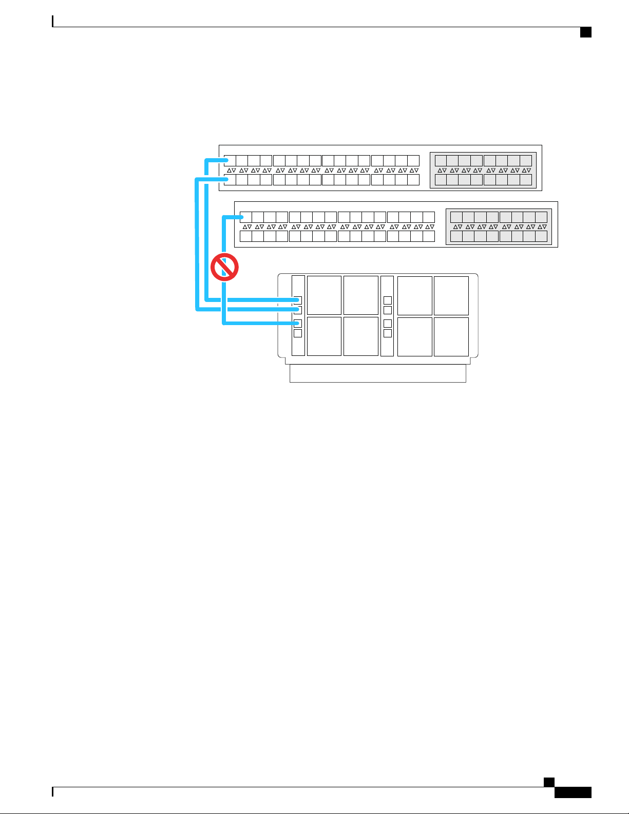
I/O Module Slot 1 I/O Module Slot 2I/O Module Slot 1 I/OModule Slot 2
Chassis 1 rear
Port 1
Port 2
Port 3
Port 4
Port 1
Port 2
Port 3
Port 4
1 3 5 7 9 11 13 15 17 19 21 23 25 27 29 31
26 28 30 3218 20 22 2410 12 14 162 4 6 8
1 3 5 7 9 11 13 15
10 12 14 162 4 6 8
1 3 5 7 9 11 13 15 17 19 21 23 25 27 29 31
26 28 30 3218 20 22 2410 12 14 162 4 6 8
1 3 5 7 9 11 13 15
10 12 14 162 4 6 8
Fabric Interconnect A Rear
Fabric Interconnect B Rear
192748
Installation
Proper FEX and Fabric Interconnect Port Connectivity
The following figure shows an invalid connection from a FEX to two separate fabric interconnects.
Figure 28: Invalid Connection for the Server Chassis and two Cisco UCS 6120XP Fabric Interconnects
Both fabric interconnects should be wired identically: if port 1 on FEX 1 for a chassis goes to FI-A
◦
port 5, then port 1 on FEX 2 goes to FI-B port 5.
The following figure shows valid connections from FEXes in two chassis to two separate fabric
interconnects. When you connect the server chassis to the fabric interconnect do not connect the
FEXes to the fabric interconnect's expansion modules. While similar in appearance to the other
Cisco UCS 5108 Server Chassis Installation Guide
OL-20035-05 49
Page 62

I/O Module Slot 1 I/O Module Slot 2I/O Module Slot 1 I/OModule Slot 2
Chassis 1 rear
Port 1
Port 2
Port 3
Port 4
Port 1
Port 2
Port 3
Port 4
1 3 5 7 9 11 13 15 17 19 21 23 25 27 29 31
26 28 30 3218 20 22 2410 12 14 162 4 6 8
1 3 5 7 9 11 13 15
10 12 14 162 4 6 8
1 3 5 7 9 11 13 15 17 19 21 23 25 27 29 31
26 28 30 3218 20 22 2410 12 14 162 4 6 8
1 3 5 7 9 11 13 15
10 12 14 162 4 6 8
Fabric Interconnect A Rear
Fabric Interconnect B Rear
I/O Module Slot 1 I/O Module Slot 2I/O Module Slot 1 I/OModule Slot 2
Chassis 2 rear
Port 1
Port 2
Port 3
Port 4
Port 1
Port 2
Port 3
Port 4
192749
Removing the Chassis from a Rack
Installation
ports on the fabric interconnect, the expansion modules are never used for direct chassis connections,
they are used for uplink or SAN connections.
Figure 29: Proper Connection for the Server Chassis and two Cisco UCS 6120XP Fabric Interconnects
Removing the Chassis from a Rack
Procedure
Step 1
Use Cisco UCS Manager to do the following:
a) Shut down the OS on all blade servers in the chassis.
b) Disable the Smart Call Home feature.
c) Decommission the chassis.
For details, see the Configuration Guide for the version of Cisco UCS Manager that you are using. The
configuration guides are available at the following URL: http://www.cisco.com/en/US/products/ps10281/
products_installation_and_configuration_guides_list.html
Cisco UCS 5108 Server Chassis Installation Guide
50 OL-20035-05
Page 63

Installation
Repacking the Chassis
Step 2
Step 3
Step 4
Step 5
Step 6
Step 7
Disconnect the power cords and networking cables from the chassis.
Remove all modules and blades from the chassis to lighten its weight.
Remove the screws holding the front rack-mount flange to the rack.
With two people holding the chassis, make sure that its weight is fully supported.
Gently slide the chassis off the rails, and out of the rack.
Replace the modules and blades in the server chassis.
Repacking the Chassis
If you need to repack the chassis, remove it from the rack by reversing the steps in the Removing the Chassis
from a Rack, on page 50 section, and then pack it for shipment. If possible, use the original packing materials
and container to pack the chassis. If you are returning the chassis to Cisco, contact your Cisco customer service
representative to arrange for return shipment to Cisco.
SFP+ Transceivers
Each FEX within the chassis supports Small Form-Factor Pluggable (SFP+) copper or optical transceivers.
Each transceiver runs at 10 Gb.
SFP+ Twinax Copper Transceivers
The FEX also supports Twinax copper transceivers. The enhanced SFP+ 10-Gb Ethernet transceiver is a
bidirectional device with a transmitter and receiver in the same physical package. It has a 20-pin connector
on the electrical interface.
Table 7: SFP+ 10 Gb Ethernet Transceiver
SFP-H10GB-CU1M
SFP-H10GB-CU3M
SFP-H10GB-CU5M
SFP-H10GB-ACU7M
SFP-H10GB-ACU10M
DescriptionModel
10-Gb Ethernet—copper SFP+ (1 m, 3.28 ft.)
10-Gb Ethernet—copper SFP+ (3 m, 9.84 ft.)
10-Gb Ethernet—copper SFP+ (5 m, 16.4 ft.)
10-Gb Ethernet—copper SFP+ (7 m, 22.9 ft.)
10-Gb Ethernet—copper SFP+ (10 m, 32.8 ft.)
Cisco UCS 5108 Server Chassis Installation Guide
OL-20035-05 51
Page 64
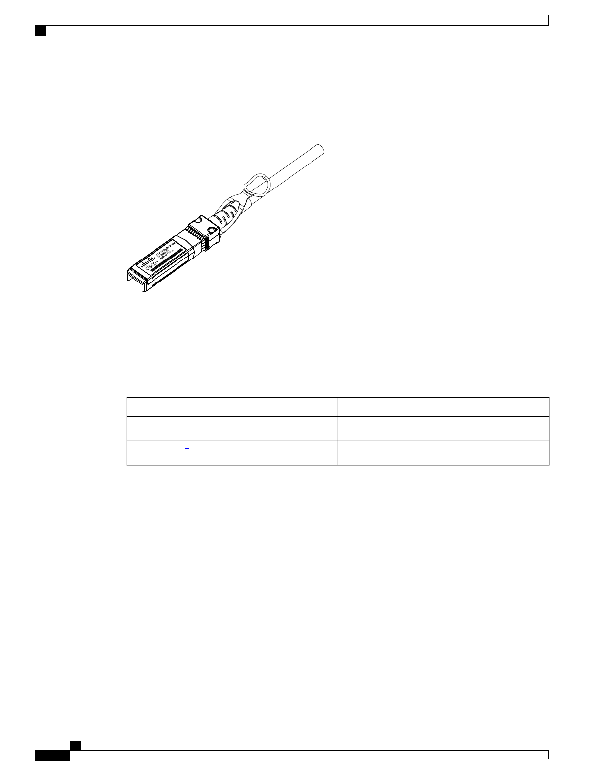
187492
Optical SFP+ Transceivers
The figure below shows the SFP-H10GB-CU5M transceiver. The rubber loop is used for removing the SFP+
from its port on the I/O module.
Figure 30: SFP+ 10 Gb Twinax Copper Transceiver
Installation
Optical SFP+ Transceivers
If distances greater than 10 meters (33 feet) must be spanned, the FEX also supports the substitution of the
copper SFP+ by optical SFP+ transceivers. The SFP+ 10-Gb Ethernet optical transceiver is a bidirectional
device with a transmitter and receiver in the same physical package. It has a duplex LC connector on the
optical interface.
DescriptionModel
SFP-10G-SR
SFP-10G-LR
4
While the SFP-10G-LR is supported by both the fabric interconnect and I/O module, the maximum distance will introduce latency issues that will affect overall
performance.
4
Documentation for SFP+ 10-Gb Ethernet optical transceivers is at
http://www.cisco.com/en/US/docs/interfaces_modules/transceiver_modules/installation/note/78_15160.html
Short–range optical SFP+ (up to 300 m/ 984 feet)
Long–range optical SFP+ (up to 10 km/6.2 miles)
Cisco UCS 5108 Server Chassis Installation Guide
52 OL-20035-05
Page 65
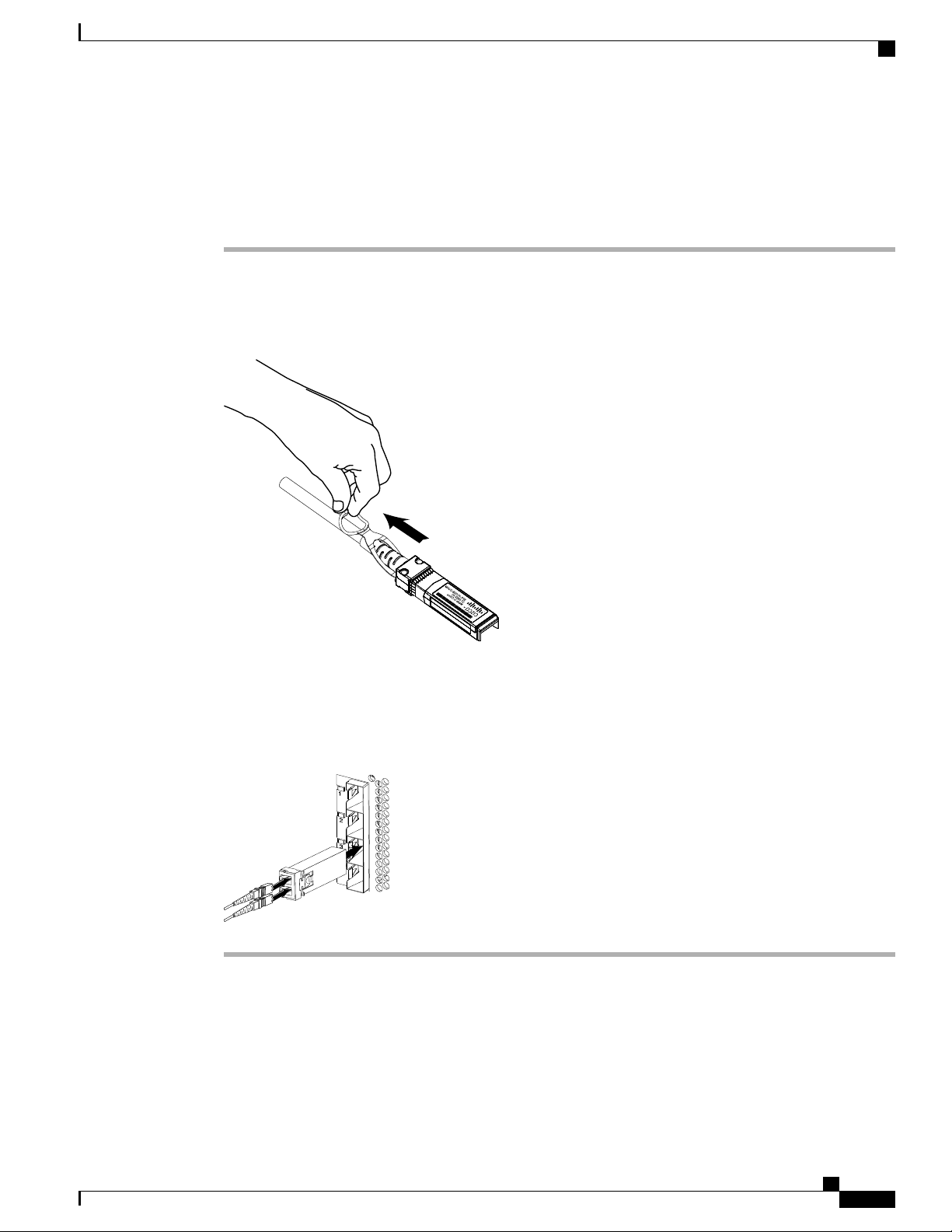
192627
192666
Installation
Replacing a Copper Twinax SFP+ Transceiver with an Optical SFP+ Transceiver
Replacing a Copper Twinax SFP+ Transceiver with an Optical SFP+ Transceiver
Procedure
Step 1
Step 2
Step 3
Remove the copper Twinax SFP+ from the FEX port by pulling gently on the rubber loop. The cable and
SFP+ transceiver come out as a single unit, leaving the FEX port empty.
Figure 31: Removing a Twinax Copper SFP+ Transceiver
Insert the optical SFP+ transceiver into the FEX port. Make sure that it clicks firmly into place.
Plug the fiber-optic cable into the optical SFP+ transceiver.
Figure 32: Replacing a Copper SFP+ Transceiver with an Optical SFP+ Transceiver
OL-20035-05 53
Cisco UCS 5108 Server Chassis Installation Guide
Page 66

Replacing a Copper Twinax SFP+ Transceiver with an Optical SFP+ Transceiver
Installation
Cisco UCS 5108 Server Chassis Installation Guide
54 OL-20035-05
Page 67

Installing and Removing Components
This chapter describes how to remove components from the chassis and how to install components into the
chassis. This section contains the following section:
Components
CHAPTER 3
Components, page 55
•
Installing and Removing a Blade Server, page 57
•
Installing and Removing Power Supplies, page 59
•
Installing and Removing a Power Distribution Unit (PDU), page 62
•
Installing and Removing FEXes, page 63
•
Installing and Removing a Fan Module, page 66
•
The following figure shows an empty Cisco UCS 5108 server chassis and identifies the front, back, and module
slots.
Cisco UCS 5108 Server Chassis Installation Guide
OL-20035-05 55
Page 68
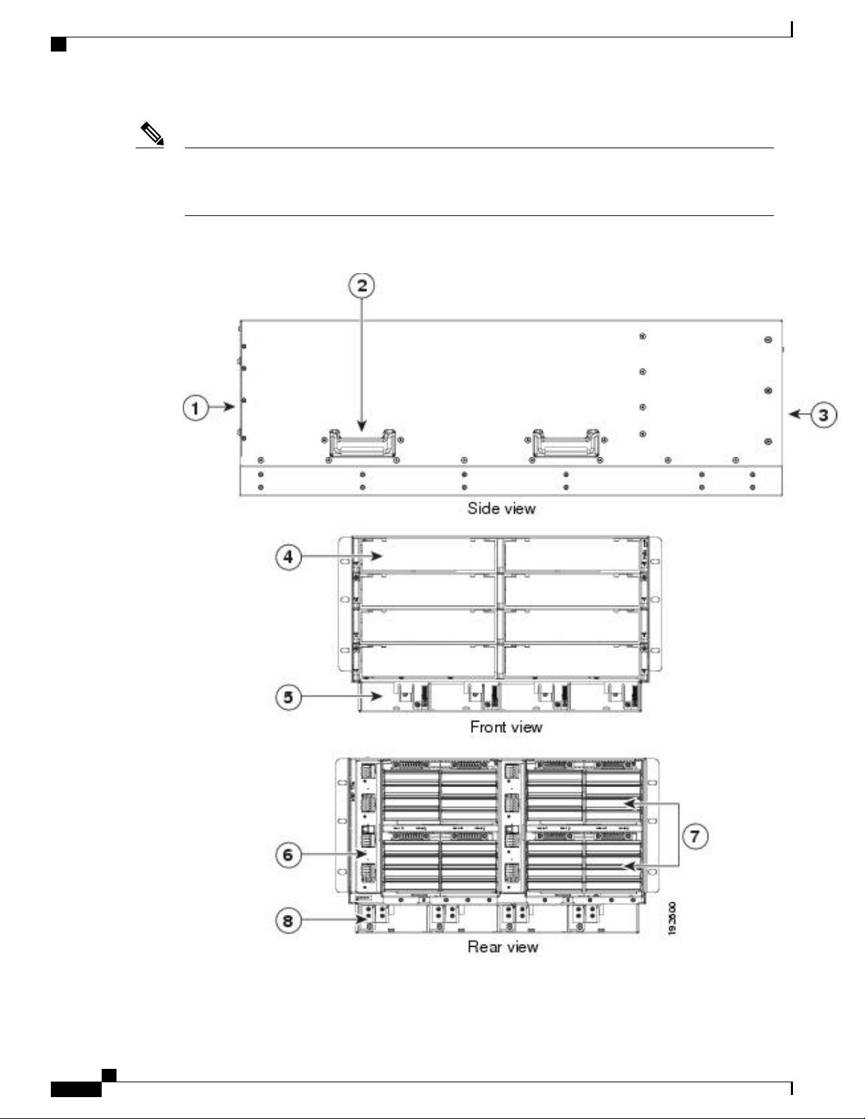
Components
Installing and Removing Components
Note
Whenever you remove a module from the chassis for an extended period of time, always replace the
module with the appropriate blank panel. Failing to do so can result in heating and EMI issues. Blank
panels can be ordered from Cisco Systems.
Figure 33: View of Cisco UCS 5108 Server Chassis
Cisco UCS 5108 Server Chassis Installation Guide
56 OL-20035-05
Page 69

Installing and Removing Components
Installing and Removing a Blade Server
Power supply slot (4 slots)5Front of chassis1
FEX slot (2 slots)6Chassis handle2
Fan slots (8 slots)7Rear of chassis3
Power Distribution Unit (PDU) slot8Half-width server slot (8 slots)4
Note
Warning
Warning
Warning
Before you install, operate, or service the system, see the Regulatory Compliance and Safety Information
for Cisco UCS for important safety information.
IMPORTANT SAFETY INSTRUCTIONS
This warning symbol means danger. You are in a situation that could cause bodily injury. Before you
work on any equipment, be aware of the hazards involved with electrical circuitry and be familiar with
standard practices for preventing accidents. Use the statement number provided at the end of each warning
to locate its translation in the translated safety warnings that accompanied this device. Statement 1071
SAVE THESE INSTRUCTIONS
This unit is intended for installation in restricted access areas. A restricted access area can be accessed
only through the use of a special tool, lock and key, or other means of security. Statement 1017
Only trained and qualified personnel must be allowed to install, replace, or service this equipment.
Statement 1030
Installing and Removing a Blade Server
There are two types of blade server supported, half-width and full-width. Their installation is similar but with
important differences. For details, see the Blade Server Installation and Service Note for the type of blade
server you are using. The server notes are available at the following URL: http://www.cisco.com/en/US/
products/ps10280/prod_installation_guides_list.html
Installing and Removing a Blade Server Hard Drive
You can remove blade server hard drives without removing the blade server from the chassis. All other
component replacement for a blade server requires removing the blade from the chassis. Unused hard drive
bays should always be covered with cover plates (N20-BBLKD) to assure proper cooling and ventilation. The
chassis is omitted from illustrations here to simplify the drawing.
Cisco UCS 5108 Server Chassis Installation Guide
OL-20035-05 57
Page 70
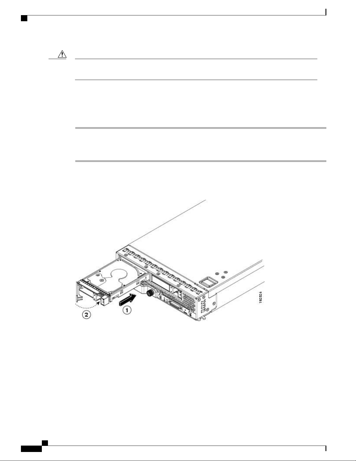
Installing and Removing a Blade Server Hard Drive
Installing and Removing Components
Caution
To prevent ESD damage, wear grounding wrist straps during these procedures and handle modules by the
carrier edges only.
Installing a Blade Server Hard Drive
Procedure
Step 1
Step 2
Step 3
Place the hard drive lever into the open position by pushing the release button.
Gently slide the hard drive into the opening in the blade server until it seats into place.
Push the hard drive lever into the closed position.
The following figure shows the positioning of a hard drive within a blade server.
Figure 34: Positioning a Hard Drive in a Blade Server (Cisco UCS B200 M1 shown)
Cisco UCS 5108 Server Chassis Installation Guide
58 OL-20035-05
Page 71
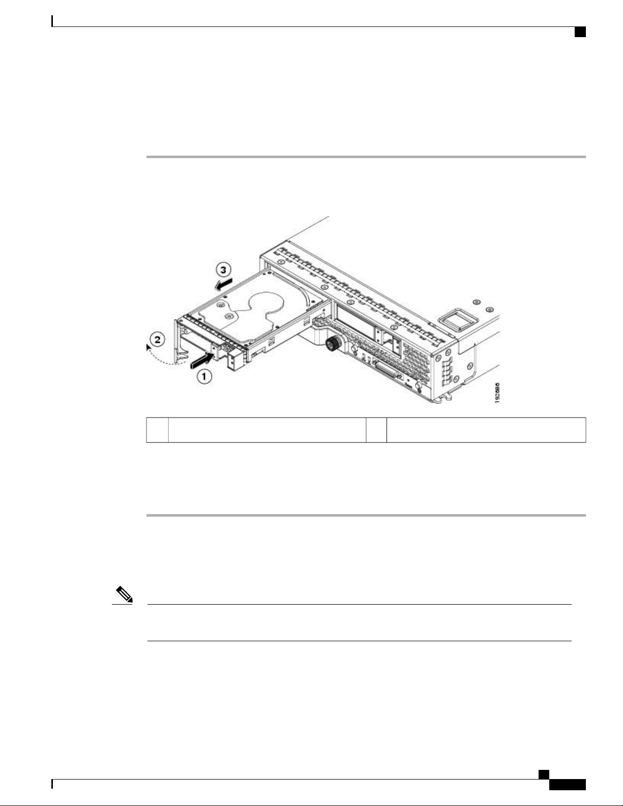
Installing and Removing Components
Removing a Blade Server Hard Drive
Procedure
Installing and Removing Power Supplies
Step 1
Push the button to release the ejector, and then pull the hard drive from its slot.
Figure 35: Pressing the Button on the Front of the Hard Drive to Deploy the Lever (Cisco UCS B200 M1 shown)
Hard drive lever2Release button1
Step 2
Step 3
Place the hard drive on an antistatic mat or antistatic foam if you are not immediately reinstalling it in another
blade server.
Install a blank faceplate (N20-BBLKD) to keep dust out of the blade server if the slot will remain empty.
Installing and Removing Power Supplies
Note
The AC and DC power supplies are keyed to work only with the power distribution system in their
respective chassis version. Mixing AC and DC in a given chassis is not supported.
Cisco UCS 5108 Server Chassis Installation Guide
OL-20035-05 59
Page 72

192520
Installing a Power Supply
Installing a Power Supply
All power supply models (N20-PAC5-2500W, UCSB-PSU-2500ACPL, or UCSB-PSU-2500DC48) install
using the same process.
Procedure
Installing and Removing Components
Step 1
Step 2
Step 3
Step 4
Step 5
Step 6
Step 7
Place the power supply’s handle in the up position.
Hold the power supply with both hands, and then slide it into the power supply bay,
Press the handle down, and give the power supply a gentle push inward to ensure that the power supply is
fully seated into the Power Distribution Unit (PDU).
Tighten the captive screw.
For an AC installation, plug the power cable into the corresponding 220 VAC–inlet connector on the PDU at
the rear of the chassis. For a DC environment, see Connecting a DC Power Supply, on page 44.
Note
Depending on the outlet receptacle on your rack’s power distribution unit, you may need the optional
jumper power cord to connect the Cisco UCS 5108 server chassis to an outlet receptacle.
Connect the other end of the power cable to the AC–power source.
Verify the power supply is operating by checking the power supply LEDs. See LED Locations, on page 24
and Interpreting LEDs, on page 25.
Figure 36: Positioning a Power Supply in the Cisco UCS Server Chassis
Cisco UCS 5108 Server Chassis Installation Guide
60 OL-20035-05
Page 73

PS 1
PS 2
PS 3
PS 4
Server Slot 1
Server Slot 2
Server Slot 3
Server Slot 5
Server Slot 7
Server Slot 4
Server Slot 6
Server Slot 8
Front
Fan 1
Fan 2
I/O Module Slot 1
I/O Module Slot 2
Connector
PS 4
Connector
PS 3
Connector
PS 2
Connector
PS 1
Fan 6
Fan 5
Fan 4
Fan 3
Fan 8
Fan 7
Rear
279770
Installing and Removing Components
Removing a Power Supply
Note
Both grids in a power redundant system should have the same number of power supplies. If your
system is configured for grid redundancy, slots 1 and 2 are assigned to grid 1 and slots 3 and 4 are
assigned to grid 2. If there are only two power supplies in a redundant- mode chassis, they should
be in slots 1 and 3. This would be a very unusual configuration, with a single B200 blade server in
the chassis. A larger configuration would require two power supplies per grid. Slot and cord connection
numbering is shown below.
Figure 37: Power Supply Bay and Connector Numbering (AC Version Shown)
Removing a Power Supply
Caution
Step 1
Step 2
Step 3
Step 4
If you are using the Cisco UCS 5108 server chassis with one power supply (this is only supported in earlier
versions of the system software), removing the power supply will cause the servers and chassis to shut
down. If you are using more than two power supplies, and you remove one of them, the servers continue
to operate as long as the other power supplies are sufficient to meet the power requirements of the number
of servers in the chassis.
Procedure
Loosen the captive screw on the front of the power supply.
Lift up the power supply’s handle to unseat the power supply.
Using the lever, pull the power supply from its slot. Place your other hand under the power supply to support
it while you slide it out of the chassis.
Install a blank power supply filler panel (N20-CBLKP) if the power supply bay is to remain empty.
Cisco UCS 5108 Server Chassis Installation Guide
OL-20035-05 61
Page 74

195360
1
Installing and Removing Components
Installing and Removing a Power Distribution Unit (PDU)
Installing and Removing a Power Distribution Unit (PDU)
Caution
Caution
The Power Distribution Unit should only be replaced by a Cisco certified technician. This section is for
reference only.
You can not hot swap a PDU (N01-UAC1). The entire chassis will need to be shut down and all power
cords should be unplugged before attempting this procedure.
Installing a PDU
Procedure
Step 1
Hold the PDU module from below, with the captive screws at the top of the module.
Figure 38: Positioning a PDU (N01-UAC1) in the Cisco UCS Server Chassis, AC Version
Step 2
Step 3
Step 4
Cisco UCS 5108 Server Chassis Installation Guide
62 OL-20035-05
Push the PDU module into the chassis until it seats properly. If power supplies are installed, you may need
to partially remove them.
Tighten the captive screws.
If necessary, reseat the power supplies and restart the system to observe LED behavior.
Page 75

Installing and Removing Components
Removing a PDU
Procedure
Removing a PDU
Step 1
Step 2
Step 3
Partially remove all installed power supplies. If a power supply is seated into the PDU, removal is difficult
or impossible.
Loosen the captive screws.
Pull the PDU clear of the chassis by pulling on the captive screws. Support its weight from below.
Installing and Removing FEXes
The chassis houses two FEXes (Cisco UCS 2104XP, UCS 2208XP, UCS 2204XP) that allow the blade servers
in the chassis to communicate with Cisco UCS fabric interconnects. FEXes can have either four or eight I/O
ports.
Note
FEX Upgrade Considerations
A FEX is sometimes referred to as an “I/OM” or IO Module.
Before you install a pair of UCS 2208XP FEXes to an existing UCS chassis using a pair of UCS 2104XPs,
or add a new chassis with a pair of UCS 2208XP FEXes to a UCS instance you must perform a full upgrade
to UCS software version 2.0(1) or later. The UCS 2208XP FEX is not recognized by earlier software releases.
Before you install a pair of UCS 2204XP FEXes to an existing UCS chassis using a pair of UCS 2104XPs,
or add a new chassis with a pair of UCS 2204XP FEXes to a UCS instance you must perform a full upgrade
to UCS software version 2.0(2) or later. The UCS 2204XP I/O Module is not recognized by earlier software
releases.
Upgrading from a pair of UCS 2104XP to a pair of UCS 2200 series modules should be done first on the FEX
connected to the standby Fabric Interconnect, standby should be made active, then the FEX connected to the
new standby Fabric Interconnect can be upgraded.
If you are also performing an upgrade on the fabric interconnects, perform the upgrades separately. Attempting
to upgrade both FEXes and fabric interconnects in a single process will likely complicate any reconfiguration
needed on the FI ports.
Adding any M3 model blade server may require an upgrade from UCS 2104XP to UCS 2208 series FEXes.
M3 blade servers use newer MLOM and adapter card models that are not fully compatible with the older FEX
model.
Before you disconnect any data cables, make a record of which FEX ports are connected to which Fabric
interconnect ports.
Cisco UCS 5108 Server Chassis Installation Guide
OL-20035-05 63
Page 76

Removing a FEX
Configurations of 1, 2, 4, or 8 10 GB connections between FEX and Fabric interconnect are supported in
UCS. If your UCS 2104XP has 4 physical connections and you want more, the next available upgrade step
is the full 8 connections on the UCS 2208XP. You should verify that the FEX upgrade is completed with no
problems before adding the connections for ports 5-8.
If you intend to implement the Fabric port channel feature available in UCS software version 2.0, you may
need to rearrange the cabling between FEX and Fabric Interconnect before performing the feature configuration.
Fabric port channel will require that all physical links from a given FEX physically connect to a contiguous
block of ports (1 to 8 or 9 to 16, and so on). This feature requires a Cisco UCS M82-8P Virtual Interface Card
in at least one blade server, and the UCS 2208XP FEX. See the Fabric Port Channel sections in the configuration
guides for more details.
Removing a FEX
Procedure
Installing and Removing Components
Step 1
Step 2
Step 3
Step 4
Step 5
Remove all cables from the FEX.
Loosen the captive screws on the FEX.
Pull the levers outward to unseat the FEX.
Using the levers, pull the FEX from its slot.
Install a blank FEX filler panel (N20-CBLKI) if the FEX slot is to remain empty.
Note
If you plan to remove a FEX for an extended period of time, you must replace it with the N20-CBLKI
blank to avoid EMI issues. Blanks can be order from Cisco.
Cisco UCS 5108 Server Chassis Installation Guide
64 OL-20035-05
Page 77

192601
237202
Installing and Removing Components
Installing a FEX
Procedure
Installing a FEX
Step 1
Step 2
Make sure that the two levers at the front of the FEX are pulled open.
Slide the FEX into the chassis slot, ensuring that the FEX is fully seated.
Figure 39: Positioning a 4 Port FEX within the Server Chassis
Figure 40: Positioning an 8 Port FEX within the Server Chassis
Step 3
Step 4
Close the levers and tighten the captive screw on each lever.
Connect the networking cables (see SFP+ Transceivers, on page 51 and Proper FEX and Fabric Interconnect
Port Connectivity, on page 48 ).
Step 5
Verify that the I/O Module is functioning correctly. See LED Locations, on page 24 and Interpreting LEDs,
on page 25.
Cisco UCS 5108 Server Chassis Installation Guide
OL-20035-05 65
Page 78

192521
Installing and Removing a Fan Module
Installing and Removing a Fan Module
You can hot swap a fan module (N20-FAN5) without causing an electrical hazard or damage to the system.
However, you can only remove one fan module while the system is operating. Removing more than one fan
module could cause overheating.
Installing and Removing Components
Note
When a fan is removed, louvers inside the chassis prevent recirculation of air into the system or loss of
cooling. However, you should not leave the chassis for extended periods of time without all fan modules
in place.
Installing a Fan Module
Procedure
Step 1
Step 2
Step 3
Step 4
Hold the fan module with the spring latch at the top of the module.
Push the fan module into the chassis until it seats properly and the spring latch snaps into place.
Listen for the fans if the chassis is powered on. You should immediately hear it operating. If you do not hear
it, ensure that the fan module is inserted completely in the chassis and the faceplate is flush with the outside
surface of the chassis.
Verify that the LED behavior is as expected. See LED Locations, on page 24 and Interpreting LEDs, on
page 25.
Figure 41: Positioning a Fan Module (N20-FAN5) in the Cisco UCS Server Chassis
Cisco UCS 5108 Server Chassis Installation Guide
66 OL-20035-05
Page 79

Installing and Removing Components
Removing a Fan Module
Procedure
Removing a Fan Module
Step 1
Step 2
Step 3
Hold the fan module by its handle.
Press down on the spring latch at the top of the fan module.
Pull the fan module clear of the chassis.
Note
The chassis is designed to have all fan modules in place and operating at all times. Do not leave a
fan module bay empty for longer than is necessary to replace it with a new fan module.
Cisco UCS 5108 Server Chassis Installation Guide
OL-20035-05 67
Page 80

Removing a Fan Module
Installing and Removing Components
Cisco UCS 5108 Server Chassis Installation Guide
68 OL-20035-05
Page 81

KVM Cable
APPENDIX A
Technical Specifications
This appendix lists the technical specifications for the Cisco UCS 5108 server chassis and includes the
following sections:
KVM Cable, page 69
•
Chassis Specifications, page 70
•
Environmental Specifications, page 71
•
Specifications for the Cisco UCS 5108 Blade Server Chassis Power Supply Units, page 72
•
Supported AC Power Cords and Plugs, page 74
•
The KVM cable (N20-BKVM) provides a connection into a Cisco UCS blade server, providing a DB9 serial
connector, a VGA connector for a monitor, and dual USB ports for a keyboard and mouse. With this cable
you can create a direct connection to the operating system and the BIOS running on a blade server.
Figure 42: KVM Cable for Blade Servers
VGA connection for a monitor3Connector to blade server slot1
Cisco UCS 5108 Server Chassis Installation Guide
OL-20035-05 69
Page 82

Chassis Specifications
Chassis Specifications
Table 8: Cisco UCS Server Chassis
Technical Specifications
2-port USB connector for a mouse and keyboard4DB9 serial connector2
SpecificationDescription
10.5 in (26.7 cm) x 17.5 in (44.5 cm) x 32 in (81.2 cm)Height x Width x Depth
8Blade server slots
2FEX slots
8Fan module bays
Table 9: Weight of the Chassis Components
B200 Blade Server
B230 Blade Server
B250 Blade Server
B440 Blade Server
4Power supply bays
1.2 Tb aggregateBackplane throughput
SpecificationDescription
90 lbs (40.83 kg)Empty chassis
2.5 lbs (1.13 kg)FEX
1.8 lbs (0.82 kg)Fan module
13.5 lbs (6.1 kg)
18.0 lbs (8.16 kg)
25 lbs (11.34 kg)
34.5 lbs (15.65 kg)
5
5
5
5
0.8 lbs (0.36 kg)Hard drive
Fully Populated UCS 5108 Server Chassis
Approximately 255 lbs (115.66 kg), depending on
models and options selected
5
The system weight listed here is an estimate for a fully configured system and will vary depending on the devices installed.
Cisco UCS 5108 Server Chassis Installation Guide
70 OL-20035-05
Page 83

Technical Specifications
Environmental Specifications
Table 10: Environmental Specifications for the Chassis
Environmental Specifications
SpecificationDescription
Temperature, operating within altitude: 0 to 10,000
feet (0 to 3,000 meters)
40,000 feet (0 to 12,000 meters)
Humidity (RH), noncondensing
Altitude
Sound Pressure Level
50 to 95°F (10 to 35°C)
–40 to 149°F (–40 to 65°C)Temperature, non-operating within altitude: 0 to
Operating: 10-90%, 28°C max. wet bulb
Nonoperating: 5-93%, 38°C max wet bulb
Operating – 0 to 10000 feet (0 to 3000 meters) Above
10,000 feet, maximum temperature decreases by 1°C
per 1000 feet (~300 meters) above 10,000 feet
Nonoperating – 40,000 ft (12,000 m)
83 dBA—at normal operating temperature.
Environmental Conditions and Power Requirement Specifications for Twinax SFP+ Transceivers
Table 11: Environmental Conditions and Power Requirement for the SFP+ Transceiver
UnitMax.Min.SymbolParameter
TSStorage temperature
OL-20035-05 71
–40
Cisco UCS 5108 Server Chassis Installation Guide
°C85
°C500TCCase temperature
V3.53.1VCCT,RModule supply voltage
Page 84

Technical Specifications
Specifications for the Cisco UCS 5108 Blade Server Chassis Power Supply Units
Specifications for the Cisco UCS 5108 Blade Server Chassis
Power Supply Units
Table 12: AC-input Gold Power Supply (N20-PAC5-2500W) Specifications
SpecificationDescription
UCS Software Release 1.0(1)Minimum Software requirement
200 to 240 VAC nominal (Range: 180 to 264 VAC)AC-input voltage
50 to 60 Hz nominal (Range: 47 to 63 Hz)AC-input frequency
15.5 A @ 200 VACAC-input current
2790 VA @ 200 VACMaximum Input VA
2500 W @ 200 to 240 VAC (up to four power supplies)Maximum output power per power supply
35 A < sub cycle durationMaximum inrush current
8525 BTUMaximum Heat Output
12 msMaximum hold up time
12 VDCPower supply output voltage
Climate Savers GoldEfficiency Rating
Efficiency (80Plus Gold Certified)
Table 13: AC-input Platinum Power Supply (UCSB-PSU-2500ACPL) Specifications
10% 20% 50% 100%
88.61% 91.64% 92.21% 90.97%
IEC320 C20Input connector
SpecificationDescription
UCS Software Release 2.0(2)Minimum Software requirement
200 to 240 VAC nominal (Range: 180 to 264 VAC)AC-input voltage
50 and 60 Hz nominal (Range: 47 to 63 Hz)AC-input frequency
< 16 Amps @ 200 VACAC-input current
Cisco UCS 5108 Server Chassis Installation Guide
72 OL-20035-05
Page 85

Technical Specifications
Specifications for the Cisco UCS 5108 Blade Server Chassis Power Supply Units
SpecificationDescription
2790 VA @ 200 VACMaximum Input VA
2500 W (up to four power supplies)Maximum output power per power supply
35 A (sub cycle duration)Maximum inrush current
8530 BTUMaximum Heat Output
12 ms @ 2500 WMaximum hold up time
12 VDC @ 208 APower supply output voltage
3.3 VDC @ 5APower supply standby voltage
Climate Savers PlatinumEfficiency Rating
Efficiency (80 Plus Platinum Certified)
20% 50% 100%
90% 94% 91%
IEC320 C20Input connector
Table 14: DC-Input Power Supply (N20-DC-2500) Specifications
SpecificationItem
Cisco UCS Software Release 2.0(1)Minimum software requirement
DC-input voltage
DC-input current
–48 to –60 VDC
62 A maximum @ –48 VDC input
2500 WOutput power
62 ACurrent draw at min voltage
50 ACurrent draw at max voltage
2.5Maximum KVA rating
DC input terminal block
Accepts Panduit LCD4-14AF-L or equivalent
barrel-type lug terminals with 90-degree angle, twohole tongue, which accommodates 1/0 AWG size
copper wire. The connector tongue width is 0.82 in,
the stud hole spacing is 5/8 in, and the hole size is 1/4
in.
8 msOutput holdup time
Cisco UCS 5108 Server Chassis Installation Guide
OL-20035-05 73
Page 86

Cordset rating: 16 A, 250 V
Length: 14 ft 0 in. (4.26 m)
Connector: IEC 60320 C19
Plug: AU20S3
Supported AC Power Cords and Plugs
DC wiring must meet your local codes and regulations, we recommend using a licensed local electrician to
install the DC wiring needed.
To determine the number of power supply units needed for the blade server, remember that each single slot
server is budgeted a max 550 W and each full width server is budgeted a max 1100 W. For a more detailed
estimate, contact Cisco Sales.
Supported AC Power Cords and Plugs
The AC power connectors on the blade server chassis PDU use an IEC 320 C20 socket. Each chassis power
supply has a separate power cord. The power cord that you use to connect the blade server power supply units
to an AC power source will have an IEC 320 C19 plug on one end and on the other end one that conforms to
the AC power outlet specifications for your country. See the following table to determine which cord to order
for your blade server chassis power supply units. When you determine which power cord you need to order,
you can verify that its plugs conform to the power outlets for your facility by clicking on its reference link.
The jumper power cords, for use in racks, are available as an optional alternative to the standard power cords.
The optional jumper power cords have an IEC C19 connector (such as a Cisco RP Series PDU) on the end
that plugs into the chassis’ PDU and an IEC C20 connector on the end that plugs into an IEC C19 outlet
receptacle. For more information, contact your Cisco Systems representative.
Technical Specifications
SpecificationItem
8525 BTUs/hrMax heat dissipation
Only the regular power cords or jumper power cords provided with the chassis are supported.Note
Australia and New Zealand
Power Cord Part Number—CAB-AC-16A-AUS
Cord Set Rating—16A, 250 VAC
Figure 43: CAB-AC-16A-AUS Power Cord for the Cisco UCS 5108 Blade Server Chassis
Cisco UCS 5108 Server Chassis Installation Guide
74 OL-20035-05
Page 87

Cordset rating: 16 A, 250 V
Length: 14 ft 0 in. (4.26 m)
113360
Connector: IEC 60320 C19
Plug: CEE 7/7
Cordset rating: 16 A, 250 V
Length: 14 ft 0 in. (4.26 m)
113361
Connector: IEC 60320 C19
Plug: IEC 309
Technical Specifications
Continental Europe
Power Cord Part Number—CAB-AC-2500W-EU
Cord Set Rating—16A, 250 VAC
Figure 44: CAB-AC-2500W-EU Power Cord for the UCS 5108 Blade Server Chassis
Continental Europe
International
Israel
Power Cord Part Number—CAB-AC-2500W-INT
Cord Set Rating—16A, 250 VAC
Figure 45: CAB-AC-2500W-INT Power Cord for the UCS 5108 Blade Server Chassis
Power Cord Part Number—CAB-AC-2500W-ISRL
OL-20035-05 75
Cisco UCS 5108 Server Chassis Installation Guide
Page 88

Cordset rating: 20 A, 250 V
Length: 14 ft 0 in. (4.26 m)
113362
Connector: IEC 60320 C19
Plug: NEMA 6-20
Japan and North America
Cord Set Rating—16A, 250 VAC
Figure 46: CAB-AC-2500W-ISRL Power Cord for the UCS 5108 Blade Server Chassis
Japan and North America
Technical Specifications
Non-Locking 200 to 240 VAC operation
Power Cord Part Number—CAB-AC-2500W-US1
Cord Set Rating—16A, 250 VAC
Figure 47: CAB-AC-2500W-US1 Power Cord for the UCS 5108 Blade Server Chassis
Locking 200 to 240 VAC Operation
Power Cord Part Number—CAB-AC-C6K-TWLK
Cisco UCS 5108 Server Chassis Installation Guide
76 OL-20035-05
Page 89
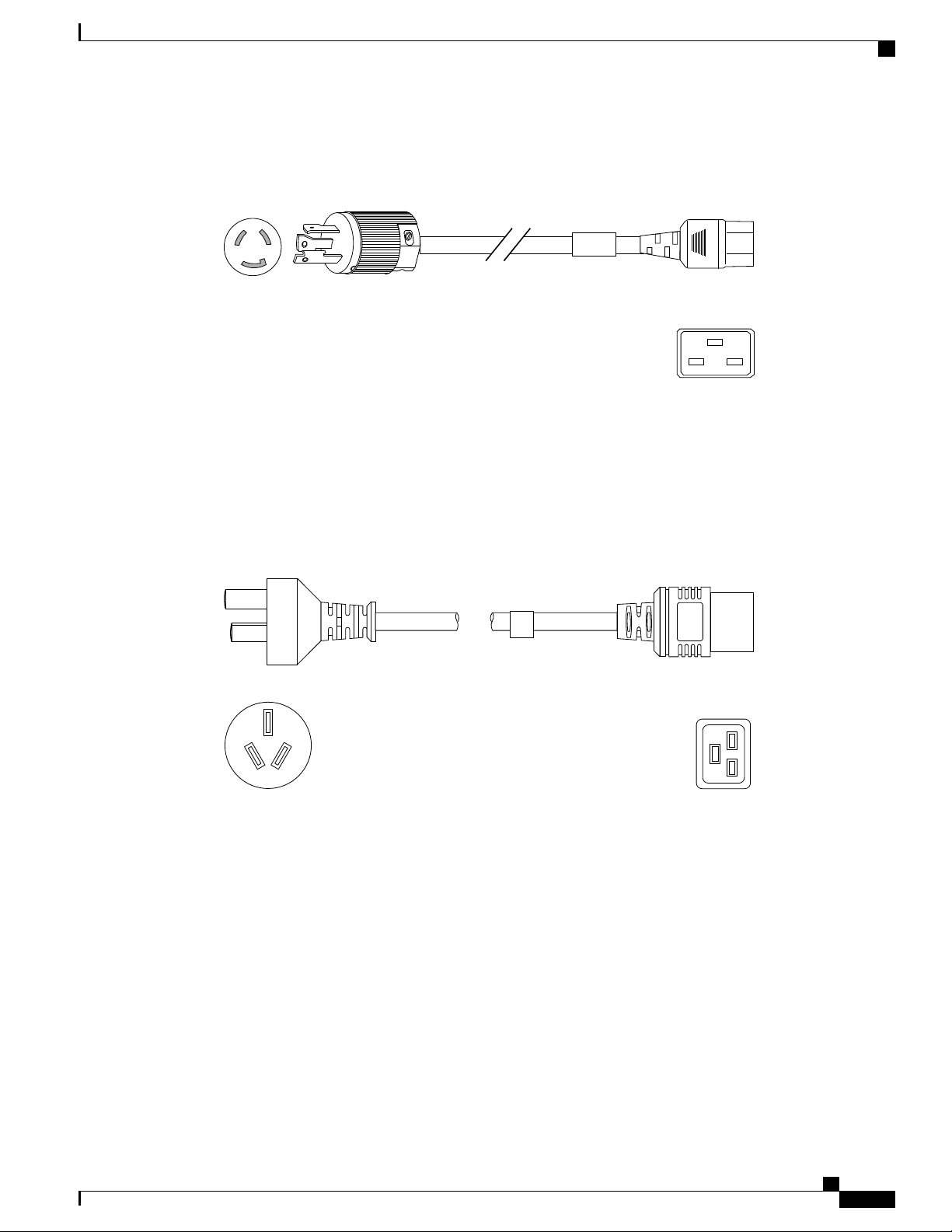
Cordset rating: 20 A, 250 V
Length: 14 ft 0 in. (4.26 m)
113363
Connector: IEC 60320 C19
Plug: NEMA L6-20
126792
Cordset rating: 16A, 250V
Length: 14 ft 0 in. (4.26 m)
Plug: GB16C
Connector: IEC
60320-1 C19
Technical Specifications
Cord Set Rating—16A, 250 VAC
Figure 48: CAB-AC-C6K-TWLK Power Cord for the UCS 5108 Blade Server Chassis
Peoples Republic of China
Power Cord Part Number—CAB-AC-16A-CH
Peoples Republic of China
Switzerland
Cord Set Rating—16A, 250 VAC
Figure 49: CAB-AC-16A-CH Power Cord for the Cisco UCS 5108 Blade Server Chassis
Power Cord Part Number—CAB-ACS-16
OL-20035-05 77
Cisco UCS 5108 Server Chassis Installation Guide
Page 90

Plug: SEV 5934-2
Type 23
Cordset rating: 16 A, 250 V
Length: 8 ft 2 in. (2.5 m)
192844
Connector: IEC 60320 C19
Cordset r ating: 16 A, 250 V
Length: 9 ft 0 in. (2.7 m)
140587
Connector :
IEC 60320 C19
Connector :
IEC 60320 C20
Power Distribution Unit (PDU)
Cord Set Rating—16A, 250 VAC
Figure 50: CAB-ACS-16 Power Cord for the UCS 5108 Blade Server Chassis
Power Distribution Unit (PDU)
Technical Specifications
Power Cord Part Number—CAB-C19-CBN
Cord Set Rating—Not applicable
Figure 51: CAB-C19-CBN Power Cord for the UCS 5108 Blade Server Chassis
Cisco UCS 5108 Server Chassis Installation Guide
78 OL-20035-05
Page 91

APPENDIX B
Site Planning and Maintenance Records
Note
For information about how to query the chassis for configuration information, see the Cisco UCS
Configuration Guide.
This appendix includes the following records to use when installing the Cisco UCS server chassis:
Site Preparation Checklist, page 79
•
Contact and Site Information, page 81
•
Chassis and Module Information, page 81
•
FEX Port Connection Record, page 83
•
Site Preparation Checklist
Planning the location and layout of your equipment is essential for successful network operation, ventilation,
and accessibility. Consider heat dissipation when sizing the air-conditioning requirements for an installation.
Table 15: Site Planning Checklist
1
Space evaluation:
Space and layout
•
DateTimeVerified ByPlanning ActivityTask No.
Floor covering
•
Impact and vibration
•
Lighting
•
Maintenance access
•
Cisco UCS 5108 Server Chassis Installation Guide
OL-20035-05 79
Page 92

Site Preparation Checklist
Site Planning and Maintenance Records
DateTimeVerified ByPlanning ActivityTask No.
2
3
Environmental evaluation:
Ambient temperature
•
Humidity
•
Altitude
•
Atmospheric contamination
•
Air flow
•
Power evaluation:
Input power type
•
Power receptacles
•
Receptacle proximity to the
•
6
equipment
Dedicated circuit for power supply
•
Dedicated (separate) circuits for
•
redundant power supplies
UPS7for power failures
•
4
5
6
6
Verify that the power supply installed in the chassis has a dedicated AC source circuit.
7
UPS: uninterruptable power supply.
Grounding evaluation:
Circuit breaker size
•
CO ground (AC- powered systems)
•
Cable and interface equipment evaluation:
Cable type
•
Connector type
•
Cable distance limitations
•
Interface equipment (transceivers)
•
EMI8evaluation:
Distance limitations for signaling
•
Site wiring
•
RFI9levels
•
Cisco UCS 5108 Server Chassis Installation Guide
80 OL-20035-05
Page 93

Site Planning and Maintenance Records
8
EMI: electromagnetic interference.
9
RFI: radio frequency interference.
Contact and Site Information
Use the following worksheet to record contact and site information.
Table 16: Contact and Site Information
Contact person
Contact phone
Contact e-mail
Building/site name
Contact and Site Information
Data center location
Floor location
Address (line 1)
Address (line 2)
City
State
Zip code
Country
Chassis and Module Information
Use the following worksheets to record information about the server chassis and the modules it contains.
Contract Number_______________________________________________
Chassis Serial Number___________________________________________
Product Number________________________________________________
Table 17: Device Information
NotesSerial NumberDevice
Blade Server–1
Cisco UCS 5108 Server Chassis Installation Guide
OL-20035-05 81
Page 94

Chassis and Module Information
Blade Server–2
Blade Server–3
Blade Server–4
Blade Server–5
Blade Server–6
Blade Server–7
Blade Server–8
I/O Module-1
Site Planning and Maintenance Records
NotesSerial NumberDevice
I/O Module-2
The serial numbers of all server chassis modules can be obtained using Cisco UCS Manager.Note
Cisco UCS 5108 Server Chassis Installation Guide
82 OL-20035-05
Page 95

Site Planning and Maintenance Records
FEX Port Connection Record
Table 18: Chassis FEX to Fabric Interconnect Port Connection Record
Connected toFEX
FEX Port Connection Record
PortNumber
11
2
3
4
5
6
7
8
12
2
3
Connection notesPortSlotFabric
Interconnect
A or B
4
5
6
7
8
Cisco UCS 5108 Server Chassis Installation Guide
OL-20035-05 83
Page 96

FEX Port Connection Record
Site Planning and Maintenance Records
Cisco UCS 5108 Server Chassis Installation Guide
84 OL-20035-05
 Loading...