

Page 1

Cisco TelePresence System 3200
Assembly Guide
Use & Care Guide
Field-Replaceable Unit Guide
July 28, 2008
Americas Headquarters
Cisco Systems, Inc.
170 West Tasman Drive
San Jose, CA 95134-1706
USA
http://www.cisco.com
Tel: 408 526-4000
800 553-NETS (6387)
Fax: 408 527-0883
Text Part Number: OL-14521-01
Page 2

THE SPECIFICATIONS AND INFORMATION REGARDING THE PRODUCTS IN THIS MANUAL ARE SUBJECT TO CHANGE WITHOUT NOTICE. ALL
STATEMENTS, INFORMATION, AND RECOMMENDATIONS IN THIS MANUAL ARE BELIEVED TO BE ACCURATE BUT ARE PRESENTED WITHOUT
WARRANTY OF ANY KIND, EXPRESS OR IMPLIED. USERS MUST TAKE FULL RESPONSIBILITY FOR THEIR APPLICATION OF ANY PRODUCTS.
THE SOFTWARE LICENSE AND LIMITED WARRANTY FOR THE ACCOMPANYING PRODUCT ARE SET FORTH IN THE INFORMATION PACKET THAT
SHIPPED WITH THE PRODUCT AND ARE INCORPORATED HEREIN BY THIS REFERENCE. IF YOU ARE UNABLE TO LOCATE THE SOFTWARE LICENSE
OR LIMITED WARRANTY, CONTACT YOUR CISCO REPRESENTATIVE FOR A COPY.
The following information is for FCC compliance of Class A devices: This equipment has been tested and found to comply with the limits for a Class A dig ital device, pursuant
to part 15 of the FCC rules. These limits are designed to provide reasonable protection against harmful interference when the equipment is operated in a commercial
environment. This equipment generates, uses, and can radiate radio-frequency energy and, if not installed and used in accordance with the instruction manual, may cause
harmful interference to radio communications. Operation of this equipment in a residential area is likely to cause harmful interference, in which case users will be required
to correct the interference at their own expense.
The following information is for FCC compliance of Class B devices: This equipment has been tested and found to comply with the lim its for a Class B digital device, pursuant
to part 15 of the FCC rules. These limits are designed to provide reasonable protection against harmful interference in a residential installation. This equipment generates,
uses and can radiate radio frequency energy and, if not installed and used in accordance with the instructions, may cause harmful interference to radio communications.
However, there is no guarantee that interference will not occur in a particular installation. If the equipment causes interference to radio or television reception, which can be
determined by turning the equipment off and on, users are encouraged to try to correct the interference by using one or more of the following measures:
• Reorient or relocate the receiving antenna.
• Increase the separation between the equipment and receiver.
• Connect the equipment into an outlet on a circuit different from that to which the receiver is connected.
• Consult the dealer or an experienced radio/TV technician for help.
Modifications to this product not authorized by Cisco could void the FCC approval and negate your authority to operate the product.
The Cisco implementation of TCP header compression is an adaptation of a program developed by the University of California, Berkeley (UCB) as part of UCB’s public
domain version of the UNIX operating system. All rights reserved. Copyright © 1981, Regents of the University of California.
NOTWITHSTANDING ANY OTHER WARRANTY HEREIN, ALL DOCUMENT FILES AND SOFTWARE OF THESE SUPPLIERS ARE PROVIDED “AS IS” WITH
ALL FAULTS. CISCO AND THE ABOVE-NAMED SUPPLIERS DISCLAIM ALL WARRANTIES, EXPRESSED OR IMPLIED, INCLUDING, WITHOUT
LIMITATION, THOSE OF MERCHANTABILITY, FITNESS FOR A PARTICULAR PURPOSE AND NONINFRINGEMENT OR ARISING FROM A COURSE OF
DEALING, USAGE, OR TRADE PRACTICE.
IN NO EVENT SHALL CISCO OR ITS SUPPLIERS BE LIABLE FOR ANY INDIRECT, SPECIAL, CONSEQUENTIAL, OR INCIDENTAL DAMAGES, INCLUDING,
WITHOUT LIMITATION, LOST PROFITS OR LOSS OR DAMAGE TO DATA ARISING OUT OF THE USE OR INABILITY TO USE THIS MANUAL, EVEN IF CISCO
OR ITS SUPPLIERS HAVE BEEN ADVISED OF THE POSSIBILITY OF SUCH DAMAGES.
Cisco and the Cisco logo are trademarks or registered trademarks of Cisco and/or its affiliates in the U.S. and other countries. To view a list of Cisco trademarks, go to this
URL: www.cisco.com/go/trademarks. Third-party trademarks mentioned are the property of their respective owners. The use of the word partner does not imply a partnership
relationship between Cisco and any other company. (1110R)
Any Internet Protocol (IP) addresses used in this document are not intended to be actual addresses. Any examples, command display output, and figures included in the
document are shown for illustrative purposes only. Any use of actual IP addresses in illustrative content is unintentional and coincidental.
Cisco TelePresence System 3200
Assembly Guide
Use & Care Guide
Field-Replaceable Unit Guide
© 2008 Cisco Systems, Inc. All rights reserved.
Page 3

Preface ix
Introduction i-ix
Conventions i-ix
Obtaining Documentation, Obtaining Support, and Security Guidelines i-x
Related Documentation i-x
Contents
CHAPTER
CHAPTER
CHAPTER
CHAPTER
1 Overview 1-1
Chapter Organization 1-1
Conventions and Terminology 1-3
Tools and Equipment List 1-3
2 Building the Display Assembly 2-1
Parts List 2-1
3 Mounting and Leveling the Plasma Displays 3-1
Parts List 3-1
Purpose of Leveling the Plasma displays 3-3
Leveling Alignment Points 3-4
Leveling Goals 3-4
4 Building the Display Shelf Assembly 4-1
Parts List 4-1
CHAPTER
CHAPTER
CHAPTER
CHAPTER
OL-14521-01
5 Building the Lighting Assembly 5-1
Parts List 5-1
6 Building the First Row Table Assembly 6-1
Parts List 6-1
7 Building the Second Row Table Assembly 7-1
Table Numbering Information Used in This Chapter 7-1
Parts List 7-1
8 Assembling the Remaining Cisco TelePresence Elements 8-1
Parts List 8-1
Cisco TelePresence System 3200
iii
Page 4

Contents
CHAPTER
CHAPTER
9 Routing Power and Signal Cables 9-1
Parts List 9-1
Power Requirements for the Cisco TelePresence 3200 9-2
10 First-Time Setup 10-1
Parts List 10-1
Loading CTS Administration Software 10-1
Configuring an Alternate TFTP Server (Optional) 10-4
Setting Up CTS Components 10-4
Setting Up the Displays 10-5
Setting Up the Cameras 10-6
Starting the Software Setup 10-7
Adjusting the Zoom 10-9
Focusing the Camera 10-12
Attaching the Camera Hood Assembly 10-15
Setting Up the Speakers 10-18
Setting Up the Microphones 10-18
Setting Up the Projector 10-20
Troubleshooting Presentation Devices 10-22
Other Devices 10-23
CHAPTER
CHAPTER
11 Use & Care Guide 11-1
Maintaining the Tabletop 11-1
Cleaning the Plasma displays 11-1
Cleaning the Camera lens 11-2
Maintaining the Projector 11-2
12 Field-Replaceable Unit Guide 12-1
Complete List of Spares for the Cisco TelePresence System 3200 12-1
Powering On the System 12-4
Replacing the Camera Cluster—Part Number CTS3K-CAM-CLST-G2= 12-5
Required Information, Tools, and Equipment 12-5
Removing and Replacing the Camera Cluster 12-5
Replacing a Plasma Display—Part Number CTS-DISP-65-GEN4= 12-6
Required Information, Tools, and Equipment 12-6
Removing Audio Components 12-7
Removing the Camera Cluster 12-8
Removing the Left Door 12-8
Cisco TelePresence System 3200
iv
OL-14521-01
Page 5

Contents
Removing a Display Shelf 12-8
Removing the Display Screen and Completing the Procedure 12-9
Replacing a Speaker—Part Number CTS-LDSPKR= 12-14
Required Information, Tools, and Equipment 12-14
Removing and Replacing a Speaker 12-15
Replacing a Codec Unit—Part Number CTS-CODEC-PRI-G2= (Primary Codec) or CTS-CODEC-SEC=
(Secondary Codec) 12-16
Required Information, Tools, and Equipment 12-16
Removing and Replacing a Codec 12-16
Replacing a Microphone—Part Number CTS-MIC= 12-18
Required Information, Tools, and Equipment 12-18
Powering Off the System 12-18
Removing and Replacing a Microphone 12-19
Replacing a Microphone Without a Microphone Extension Cable 12-19
Replacing a Microphone With a Microphone Extension Cable 12-20
Replacing a Light Fixture—Part Number CTS-LIGHT-FIXT= 12-22
Required Information, Tools, and Equipment 12-22
Replacement Bulbs 12-22
Replacing a Light Fixture 12-22
Replacing the Audio/Video Extension Unit—Part Number CTS-AV-EXP= 12-23
Replacing the Auxiliary Control Unit—Part Number CTS-LIGHT-CTRL= 12-24
Replacing the Cisco Unified IP Phone—Part Number CP-7975G-CTS= 12-25
Replacing the Projector Lamp—Part Number CTS-PRJTR-BL-GEN1= or CTS-PRJTR-GEN2-CH
(China) 12-25
Replacing the Projector—Part Number CTS-PRJTR-GEN1= 12-27
Replacing a PDU—Part Number CTS-PWR-PDU= 12-27
Replacing a Display Shelf 12-28
Required Information, Tools, and Equipment 12-28
Removing and Replacing a Display Shelf Row Table Section 12-29
Replacing a First Row Table Top Section 12-30
Required Information, Tools, and Equipment 12-30
Removing and Replacing a First Row Table Top Section 12-31
Replacing a Second Row Table Top Section 12-32
Required Information, Tools, and Equipment 12-32
Removing and Replacing a Second Row Table Top Section 12-33
Appendix A: Parts List Sorted by Carton A-1
Overview A-1
Carton 1 of 58: Mechanical Accessory Kit, CTS3K-ACC-KIT, 53-2855-xx A-1
OL-14521-01
Cisco TelePresence System 3200
v
Page 6

Contents
Carton 2 of 58: Mechanical Accessory Kit, 53-2855-xx, CTS3K-ACC2-KIT A-3
Carton 3 of 58: Primary Codec, CTS-CODEC-PRI-G2, 800-30638-xx A-3
Carton 4 of 58: Camera Cluster, 800-30872-xx, CTS3K-CAM-CLST-G2 A-4
Carton 5 of 58: Secondary Codec, 800-28202-xx, CTS-CODEC-SEC A-4
Carton 6 of 58: Secondary Codec, 800-28202-xx, CTS-CODEC-SEC A-4
Carton 7 of 58: Projector, 74-4824-xx, CTS-PRJTR-GEN1 A-5
Carton 8 of 58: Speaker, 74-4740-xx, CTS-LDSPKR A-5
Carton 9 of 58: Speaker, 74-4740-xx, CTS-LDSPKR A-5
Carton 10 of 58: Speaker, 74-4740-xx, CTS-LDSPKR A-5
Carton 11 of 58: Power Cord, 37-08xx-xx, PWR-CORD10-xx A-5
Carton 12 of 58: Camera Assembly Bracket, 69-1627-xx, CTS3K-STRUCTURE A-6
Carton 13 of 58: Brackets, 69-1632-xx, CTS3K-STRUCTURE A-6
Carton 14 of 58: Privacy Panel, Right Wing, 69-1628-xx, CTS3K-STRUCTURE A-6
Carton 15 of 58: Front Foot Stabilizer, 69-1624-xx, CST3K-STRUCTURE A-6
Carton 16 of 58: Front Foot Stabilizer, 69-1624-xx, CST3K-STRUCTURE A-7
Carton 17 of 58: Front Foot Stabilizer, 69-1624-xx, CST3K-STRUCTURE A-7
Carton 18 of 58: Display Structure Rear Feet, 69-1625-xx, CTS3K-STRUCTURE A-7
Carton 19 of 58: Accessory Cabinet Brackets, 69-1630-xx, CTS3K-STRUCTURE A-7
Carton 20 of 58: Accessory Kit for CTS-3200, 53-3108-xx, CTS32-ACC-KIT A-8
Carton 22 of 58: Auxiliary Control Unit, CTS-LIGHT-CTRL A-8
Carton 23 of 58: Plasma Display, 74-4881-xx, CTS-DISP-65-GEN2 A-8
Carton 24 of 58: Plasma Display, 74-4881-xx, CTS-DISP-65-GEN2 A-9
Carton 25 of 58: Plasma Display, 74-4881-xx, CTS-DISP-65-GEN2 A-9
Carton 26 of 58: Second Row Tabletops and Accessory Kit, CTS32-M-2TBL-G2, 69-1853-xx A-9
Carton 27 of 58: Light Fixture, 74-5361-xx, CTS-LIGHT-FIXT A-10
Carton 28 of 58: Light Fixture, 74-5361-xx, CTS-LIGHT-FIXT A-10
Carton 29 of 58: Light Fixture, 74-5361-xx, CTS-LIGHT-FIXT A-10
Carton 30 of 58: Light Fixture, 74-5362-xx, CTS-LIGHT-FIXT A-11
Carton 31 of 58: Light Fixture, 74-5362-xx, CTS-LIGHT-FIXT A-11
Carton 32 of 58: Camera Target, 69-1674-xx, CTS-CAM-TOOL A-11
Carton 33 of 58: Support Crossbars, 69-1623-01, CTS3K-STRUCTURE A-12
Carton 34 of 58: Privacy Panels, 69-1629-xx, CTS3K-STRUCTURE A-12
Carton 35 of 58: Display Structure, 69-1622-xx, CTS3K-STRUCTURE A-12
Carton 36 of 58: Display Structure, 69-1622-xx, CTS3K-STRUCTURE A-12
Carton 37 of 58: Display Structure, 69-1622-xx, CTS3K-STRUCTURE A-13
Cisco TelePresence System 3200
vi
OL-14521-01
Page 7

Contents
Carton 38 of 58: Presentation Codec, 69-1887-xx, CTS-HFR-COLLAB-3K A-13
Carton 39 of 58: Spare Fluorescent Bulbs for Light Fixture, 74-5232-xx, CTS-3000-SPR-BULBS A-13
Carton 40 of 58: Secondary Codec, 800-28202-xx, CTS-CODEC-SEC A-14
Carton 41 of 58: Foam Bumpers, 69-1634-xx, CTS3K-STRUCTURE A-14
Carton 42 of 58: Foam Bumpers, 69-1634-xx, CTS3K-STRUCTURE A-14
Carton 43 of 58: Foam Bumpers, 69-1634-xx, CTS3K-STRUCTURE A-14
Carton 44 of 58: Lighting Assembly, 69-1613-xx, CTS3K-LIGHT-STR A-15
Carton 45 of 58: Projector Bracket, 69-1631-xx, CTS3K-STRUCTURE A-15
Carton 46 of 58: Projector Screen, 74-5416-xx, CTS3K-SCREEN A-15
Carton 47 of 44: Accessory Cabinet, Left, 69-1838-xx, CTS3K-FUR-MAPLE A-15
Carton 48 of 44: Accessory Cabinet, Right, 69-1837-xx, CTS3K-FUR-MAPLE A-16
Carton 49 of 58: Lighting Assembly, 69-1612-xx, CTS3K-LIGHT-STR A-16
Carton 50 of 58: Cisco TelePresence 3200 Structure—Addition to Standard CTS-3000,
CTS32-STRUCTURE, 69-1854-01 A-17
Carton 51 of 58: Display Shelf Supports and Codec Tray, 69-1626-xx, CTS3K-STRUCTURE A-18
Carton 52 of 58: Tabletop Leg Base, 69-1620-xx, CTS3K-STRUCTURE A-18
Carton 53 of 58: Tabletop Leg Base, 69-1914-xx, CTS3K-STRUCTURE A-18
Carton 54 of 58: Tabletop Leg Base, 69-1915-xx, CTS3K-STRUCTURE A-19
Carton 55 of 58: Lighting Assembly, 69-1613-xx, CTS3K-LIGHT-STR A-19
Carton 56 of 58: Projector Bracket, 69-1631-xx, CTS3K-STRUCTURE A-19
Carton 57 of 58: Foam Bumpers, 69-1634-xx, CTS3K-STRUCTURE A-19
Carton 58 of 58: Tabletop Sections, Display Shelves, and Speaker Boards, 69-1835-xx, CTS3K-M A-20
Appendix B: Region- and Country-Specific Equipment B-1
Asia Pacific B-2
Argentina B-3
Australia B-4
Central Europe B-5
China B-6
India, UAE, South Africa B-7
Israel B-8
Italy B-9
Japan B-10
North America B-11
Switzerland B-12
United Kingdom B-13
OL-14521-01
Cisco TelePresence System 3200
vii
Page 8

Contents
CHAPTER
C Cisco TelePresence System 3200 Pallet Dimensions and Description C-1
Cisco TelePresence System 3200
viii
OL-14521-01
Page 9

Introduction
Preface
Revised: July 28, 2008, OL-14521-01
The Cisco TelePresence 3200 Assembly Guide outlines the steps and best practices for assembling and
installing the Cisco TelePresence 3200.
This guide is intended primarily for installers of the Cisco TelePresence System 3200. Site planners,
network administrators, and facility maintenance personnel may also find this document useful.
This preface provides the following information for using this guide and for accessing other resources.
• Conventions, page ix
• Obtaining Documentation, Obtaining Support, and Security Guidelines, page x
• Related Documentation, page x
Conventions
This document uses the following conventions to convey information and alert the user to conditions
requiring special awareness.
Warning
Caution Means reader be ca reful. In this situation, you might do something that could result in equipment
Note Means reader take note. Notes contain helpful suggestions or references to material not covered in the
This warning symbol means danger. You are in a situation that could cause bodily injury. Before you
work on any equipment, you must be aware of the hazards involved with electrical circuitry and
familiar with standard practices for preventing accidents.
damage or loss of data.
publication.
OL-14521-01
Cisco TelePresence System 3200
ix
Page 10

Obtaining Documentation, Obtaining Support, and Security Guidelines
Tip Means the information contains useful tips.
Obtaining Documentation, Obtaining Support, and Security
Guidelines
For information on obtaining documentation, submitting a service request, and gathering additional
information, see the monthly What’s New in Cisco Product Documentation, which also lists all new and
revised Cisco technical documentation, at:
http://www.cisco.com/en/US/docs/general/whatsnew/whatsnew.html
Subscribe to the What’s New in Cisco Product Documentation as a Really Simple Syndication (RSS) feed
and set content to be delivered directly to your desktop using a reader application. The RSS feeds are a free
service and Cisco currently supports RSS version 2.0.
Preface
Related Documentation
The Cisco TelePresence system documentation set includes a variety of online and printed guides
designed to aid the assemblers, installers, system administrators, and users in the setup, configuration,
administration, and use of the Cisco TelePresence. These documents include:
• Cisco TelePresence Hardware Options and Upgrade Guide, OL-16441-01
• Cisco TelePresence System 1000 Assembly, Use & Care, and Field Replacement Unit Guide,
OL-16247-01. There is also a pointer document for this guide, 78-17800-02.
• Cisco TelePresence System 3000 Assembly, Use & Care, and Field Replacement Unit Guide,
OL-16246-01. There is also a pointer document for this guide, 78-17795-02.
• Cisco TelePresence and Cisco Unified Communications Manager Installation and Configuration
Guide, OL-11326-02
• Cisco TelePresence System Release 1.4 Administrator’s Guide, OL-13676-03
• Release Notes for Cisco TelePresence System, Release 1.4, OL-12074-05
• Cisco TelePresence Meeting User’s Guide, 78-17791-01
• Cisco TelePresence System Release 1.4 Meeting Quick Reference, 78-17792-02
• Cisco TelePresence Manager Release 1.3 Administration and Installation Guide, OL-13673-02
• Cisco TelePresence Manager Release Notes, OL-11298-01
All of these documents are available at the Cisco documentation website.
Cisco TelePresence System 3200
x
OL-14521-01
Page 11

Overview
Revised: July 28, 2008, OL-14521-01
Chapter Organization
Chapter 1, “Overview” (this chapter)
• Provides chapter organization and content of this document and an overview of the steps you
perform to install a CTS 3200 system.
Chapter 2, “Building the Display Assembly”
• The steps for assembling the three Display structures, connecting them, and positioning them in the
conference room are described in a series of illustrations.
• Each illustration builds upon the previous illustration to describe the complete process of building
the Display assembly.
CHA PTER
1
• Each illustration is keyed numerically to the Chapter Parts List, appearing at the beginning of the
chapter. You can refer to the Parts List to identify the specific fastener or bracket being used in an
illustration.
• Additional information may appear below each illustration.
Chapter 3, “Mounting and Leveling the Plasma Displays”
• This chapter uses illustrations to describe the leveling alignment points and the processes used to
level the plasma displays. This chapter is organized the same as Chapter 2.
Chapter 5, “Building the Lighting Assembly”
• This chapter describes the procedures used to build the lighting assembly and is organized the same
as Chapter 2.
Chapter 4, “Building the Display Shelf Assembly”
• This chapter describes how to build the display shelf assembly and is organized the same as Chapter
2.
Chapter 6, “Building the First Row Table Assembly”
• This chapter describes the procedure to build the first row table and is organized the same as Chapter
2.
OL-14521-01
Cisco TelePresence System 3200
1-1
Page 12

Chapter Organization
Chapter 1 Overview
Chapter 7, “Building the Second Row Table Assembly”
• This chapter describes how to build the second row table and is organized the same as Chapter 2.
Chapter 8, “Assembling the Remaining Cisco TelePresence Elements”
• This chapter is organized the same as Chapter 2.
• Each element is described using one or more illustrations. The elements are:
–
Camera assembly—attaches to the center Display structure
–
Front row table leg wiring assembly—wired for power and network connectivity
–
Projector assembly—attaches to the underside of the center table segment
–
Codec and Audio/Video Extension Unit assembly—attach the codecs to each Display
structure and attach the extension unit to the center display structure
–
Speaker assembly—attach to the underside of the Display shelf
–
Projector Screen assembly—attaches to the underside of the Display shelf
–
Cisco Unified IP Phone 7975—used for initial configuration of the Cisco TelePresence system
and to join meetings
–
Camera Target assembly—used for camera focus and alignment
Chapter 9, “Routing Power and Signal Cables”
• A series of illustrations are used to describe the routing and connection of power and signal cables
for the front row and the display assembly area.
• Illustrations show you the routing path to take for all cables.
• Illustrations showing cables terminating in a Codec include a close-up of the Codec.
Chapter 10, “First-Time Setup”
• This chapter describes the configuration you perform to set up your Cisco TelePresence System
3200 for the first time.
Chapter 11, “Use & Care Guide”
• This chapter provides information on maintaining several elements of the
Cisco TelePresence System 3200, including the tabletop and plasma displays.
Chapter 12, “Field-Replaceable Unit Guide”
• This chapter describes removal and replacement processes for various elements of the
Cisco TelePresence System 3200.
Appendix A: Parts List Sorted by Carton
• This appendix lists all parts included in the individual chapter parts lists, and sorts the list by carton.
Appendix B: Region- and Country-Specific Equipment
• This appendix lists the part numbers for all region- and country-specific equipment, including table
leg wiring and power cords.
Figure 1-1 View of an Assembled Cisco TelePresence System 3200, Standard Configuration
Step 1 Install and connect the camera assembly. See Step 1 and Step 2 in Chapter 8, “Assembling the
Remaining Cisco TelePresence Elements” to install the camera assembly and Step 13 in Chapter 9,
“Routing Power and Signal Cables” to connect the camera cables.
Cisco TelePresence System 3200
1-2
OL-14521-01
Page 13

Chapter 1 Overview
157702
Step 2 Install and connect the PDUs for the display and first row table assembly. See Step 1 through Step 3 in
Step 3 Connect the projector to the projector bracket and connect the projector and bracket to the table
Step 4 Place the Cisco Unified IP Phone on the first row table and connect the phone cable. See Step 4 in
Step 5 Install the privacy panels for the first row table. See Step 15 through Step 18 in Chapter 6, “Building the
Step 6 Install the speaker boards and speakers. See Step 8 through Step 10 in Chapter 8, “Assembling the
Step 7 Install the projector screen. Refer to the projector screen installation guide that is packaged with the
Step 8 Connect the power cables for the codecs, lighting and table leg power connections by completing Step 4
Step 9 Connect the signal cables for the first row table by completing Step 5 in Chapter 9, “Routing Power and
Conventions and Terminology
Chapter 9, “Routing Power and Signal Cables” to install the PDUs and Step 4 in Chapter 9, “Routing
Power and Signal Cables” to connect the cables.
assembly. See Step 2 and Step 3 in Chapter 8, “Assembling the Remaining Cisco TelePresence
Elements” to connect the projector to the table assembly and Step 4 in Chapter 9, “Routing Power and
Signal Cables” to connect the cables.
Chapter 9, “Routing Power and Signal Cables” to connect the cable.
First Row Table Assembly.”
Remaining Cisco TelePresence Elements.”
assembly.
in Chapter 9, “Routing Power and Signal Cables.”
Signal Cables.”
Step 10 Assemble the camera targets by completing Step 15 in Chapter 8, “Assembling the Remaining
Cisco TelePresence Elements.”
Step 11 Perform first-time setup using the instructions in Chapter 10, “First-Time Setup.”
Conventions and Terminology
• The directions left and right in this guide are synonymous with participant’s left and participant’s
right. They refer to the assembly as you face the Plasma displays.
• Cable connections to the Codecs are labeled with a color-coded symbol system.
–
A single dot on a green background indicates a center element.
–
Two dots on a white background indicate a left element.
–
Three dots on a red background indicate a right element.
Figure 1-2 Cable Connection Labeling System
Tools and Equipment List
To assemble the Cisco TelePresence System 3200, you need the following tools and equipment:
Uncrating and Unpacking:
• Claw hammer or small pry bar
OL-14521-01
Cisco TelePresence System 3200
1-3
Page 14

Tools and Equipment List
• Large Phillips screwdriver
• Tin snips*
• Pallet jack or hand cart (for moving component boxes to installation site)*
• Safety gloves*
• Safety glasses*
• Box cutters*
Cisco TelePresence System 3200 Structure, Accessory, and Adjustment Assembly:
• Power screwdriver with 3, 4, 5, and 6 mm (standard or round) Allen bits, or standard 3, 4, 5, and
Tip A round-head Allen bit can work at an angle instead of just straight out, a helpful feature in tight
• Manual screwdrivers, #2 and #4 Phillips and flathead types
• Metric wrenches, 10 to 15 mm
• 9/64-inch Allen wrench (included with speakers)
Chapter 1 Overview
6 mm Allen wrenches
spots.
• Tape measure
• Level
• Masking tape*
• Tie wr aps*
• Knee pads or kneeling cushion*
• Laptop computer attached to network (for troubleshooting or reference)*
• Hand vacuum or facilities vacuum*
• Stepladder*
• 10mm open end ratcheting wrench**
• Mechanical lift (optional, for hanging display screens)
* Recommended for best results
**Useful for securing the draw bolts between table sections
Cisco TelePresence System 3200
1-4
OL-14521-01
Page 15

CHA PTER
Building the Display Assembly
Revised: February 10, 2010, OL-14521-01
Parts List
Key Part Description Part Number Qty Ctn Notes
1
Display structure 700-23358-xx 3 35,
36,
37
2
Rear foot stabilizer 700-23360-xx
Kit# 69-1625-xx
3
Front foot stabilizer 700-23359-xx
Kit # 69-1624-xx
4
Leveling foot 51-4540-xx
Kit # 69-1654-xx
5
Display shelf support left 700-23339-xx
Kit # 69-1626-xx
6
Display shelf support right 700-23340-xx
Kit # 69-1626-01
7
Display tilt bracket 700-23363-xx 6 13
8
Codec safety tray 700-23341-xx
Kit # 69-1626-xx
9
Camera assembly bracket 700-23346-xx
Kit # 69-1627-xx
10
Support crossbars 700-23361-xx
Kit # 69-1623-xx
11
M8 x 70 mm screws 48-2274-01 1
12
M8 washers 49-1165-01 1
13
M8 x 20 mm screws 48-2273-01 1
6 18
6 15,
16,
17
12 1
51 45
51 45
3 51 If you are installing a presentation codec, use the
double-wide codec tray part no. 700-25301-01
for the center display assembly.
1 12 For center display structure only
4 33
2
OL-14521-01
Cisco TelePresence System 3200
2-1
Page 16
Parts List
201100
3
2
4
Chapter 2 Building the Display Assembly
Caution The display structures are unstable during assembly. Use caution, and support all structures as required.
Caution Some system components have metal and plastic edges with hard angles. These edges are exposed until
you complete system assembly. Use caution when you move around the system during assembly to avoid
contact with any exposed system edges.
Warning
Note The directions left and right refer to the assembly as you face the Plasma displays.
Note Before you start to build the structure, make sure that the floor in the installation room is level. An
Only trained and qualified personnel should be allowed to install, replace, or service this equipment.
uneven floor can make it difficult or, in severe cases, impossible to align the plasma displays after you
build the structure and mount the displays.
Step 1 Attach the Leveling feet to the Rear and Front Foot stabilizers.
Figure 2-1 Leveling feet
Note Figure 2-8 shows the correct positioning of the display structure; keep this in mind as you build the
structure.
Cisco TelePresence System 3200
2-2
OL-14521-01
Page 17
Chapter 2 Building the Display Assembly
201102
8
1112
Step 2 Attach the Codec Safety trays to the Front Foot stabilizers.
Note If you ordered a Presentation Codec, attach the larger tray that comes with the Presentation Codec
package, part no. 700-25301-01, in the center display. To install the presentation codec, refer to the
“Options for the Cisco TelePresence System 3200” chapter of the Cisco TelePresence Hardware Options
and Upgrade Guide1Codec Safety trays
Parts List
1.
OL-14521-01
Cisco TelePresence System 3200
2-3
Page 18

Parts List
201101
3
12
11
2
1
Chapter 2 Building the Display Assembly
Step 3 Attach the Rear and Front Foot stabilizers to the Display structures.
Figure 2-2 Rear and Front Foot stabilizers
Cisco TelePresence System 3200
2-4
OL-14521-01
Page 19
Chapter 2 Building the Display Assembly
201103
5
12
11
6
1
Step 4 Attach the left and right Display Shelf supports to each Display structure.
Figure 2-3 Left and Right Display Shelf supports
Parts List
OL-14521-01
Cisco TelePresence System 3200
2-5
Page 20
Parts List
201104
7
13
12
7
1
Chapter 2 Building the Display Assembly
Step 5 Attach the Display Tilt brackets to each Display structure.
Figure 2-4 Display Tilt brackets
Note Do not tighten the Display Tilt brackets. You will need to adjust them to level the Plasma displays in
Chapter 3, “Mounting and Leveling the Plasma Displays.”
Cisco TelePresence System 3200
2-6
OL-14521-01
Page 21

Chapter 2 Building the Display Assembly
201105
1
9
13
13
Step 6 Attach the Camera Assembly bracket to the center Display structure, making sure that this structure uses
the larger codec tray.
Figure 2-5 Camera Assembly bracket
Parts List
OL-14521-01
Note The Camera Assembly bracket attaches to the center Display structure.
Cisco TelePresence System 3200
2-7
Page 22
Parts List
201107
10
12
10
1
11
Chapter 2 Building the Display Assembly
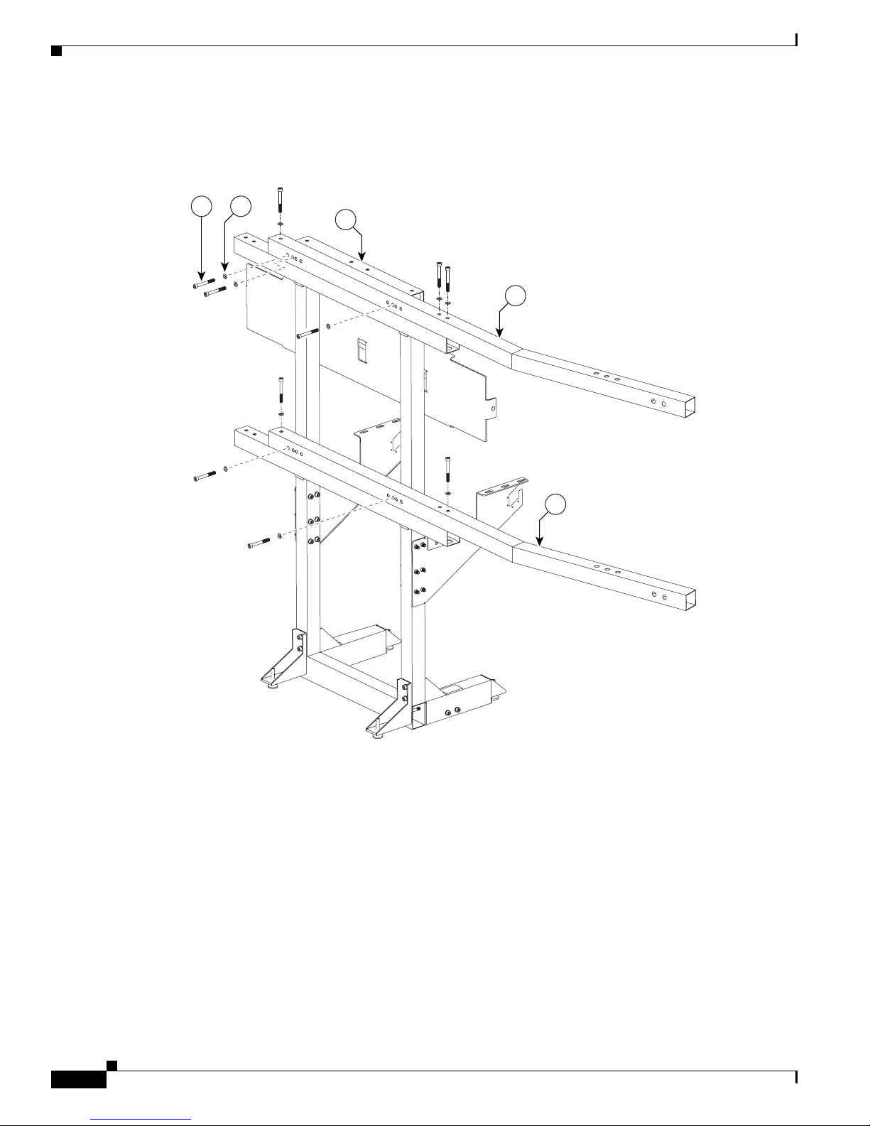
Step 7 Attach the upper and lower Support crossbars to the left and right Display structures.
Figure 2-6 Upper and Lower Support crossbars
Cisco TelePresence System 3200
2-8
OL-14521-01
Page 23
Chapter 2 Building the Display Assembly
201108
10
12
10
1
10
10
11
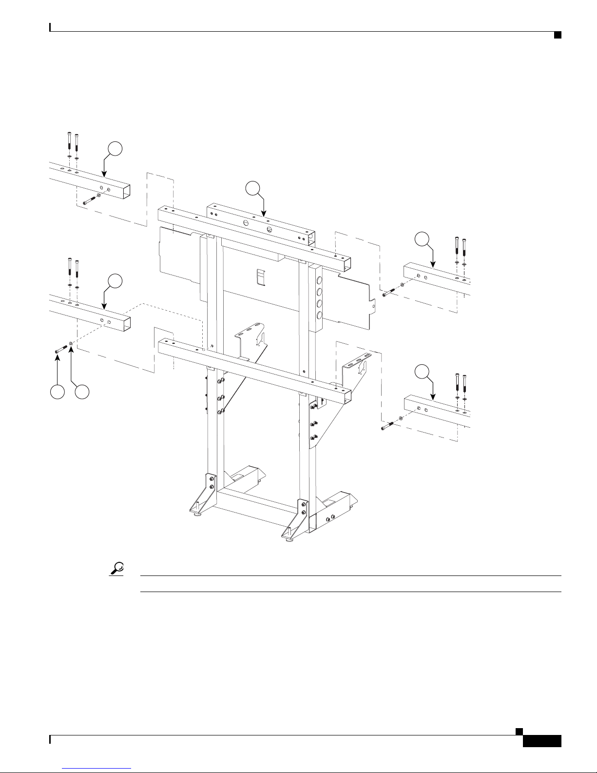
Step 8 Attach the upper and lower Support crossbars to the center Display structure.
Figure 2-7 Upper and Lower Support crossbars
Parts List
Tip Use the screw holes nearest the ends of the Support crossbars.
OL-14521-01
Cisco TelePresence System 3200
2-9
Page 24
Parts List
204152
Minimum 12 inches (30.5 cm)
Minimum 24 inches
(70 cm)
Minimum 24 inches
(70 cm)
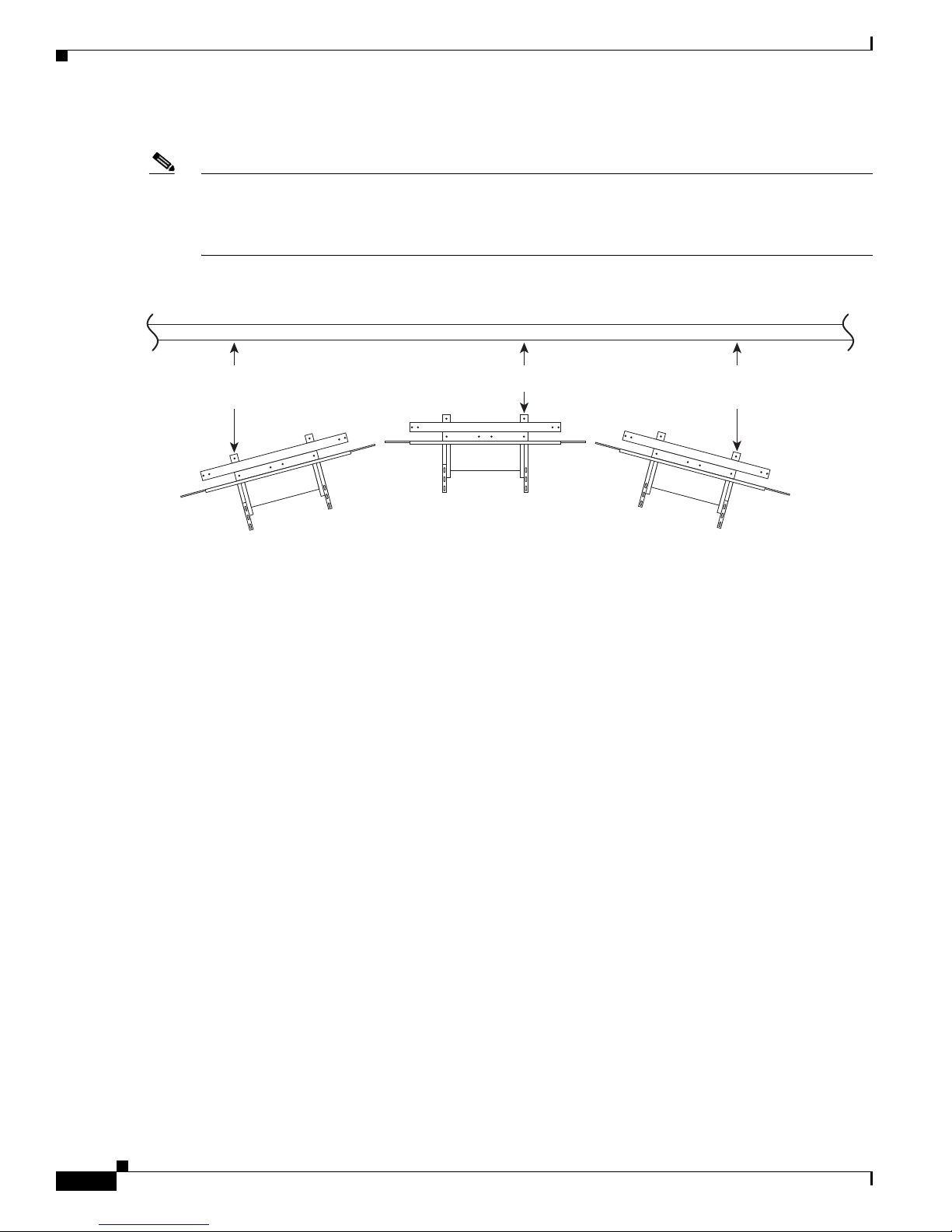
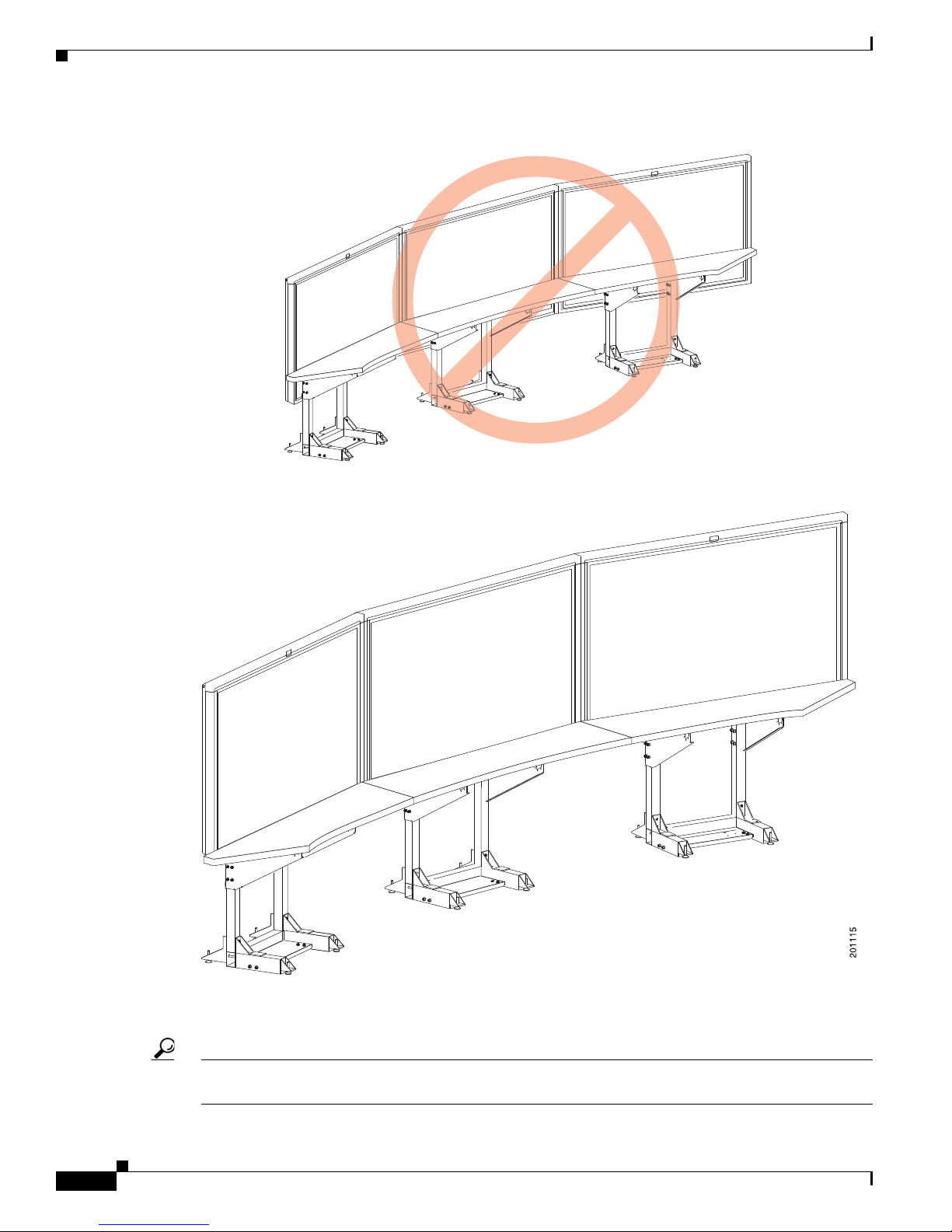
Step 9 Position the three Display structures relative to the rear wall.
Note Using the measurements provided in Figure 2-8, there will be approximately 3 inches (8 cm) of space
between the light reflector and the wall. These minimum dimensions can make installation of the light
reflector difficult. If your room size and room lighting pattern allow extra space, add extra space to these
minimum measurements.
Figure 2-8 Positioning the Display Structures
Chapter 2 Building the Display Assembly
Cisco TelePresence System 3200
2-10
OL-14521-01
Page 25
CHA PTER
Mounting and Leveling the Plasma Displays
Revised: September 16, 2009, OL-14521-01
Parts List
Key Part Description Part Number Qty Ctn Notes
1
65-inch high-definition display CTS-DISP-65-
GEN2
74-4881-xx
2
Black buffer strips 700-23981-xx 2 1
Display shelf section: left 95-9692-xx
Kit #
74-5304-xx
Display shelf section: center 95-9694-xx
Kit #
74-5306-xx
Display shelf section: right 95-9693-xx
Kit #
74-5305-xx
M8 x 20 mm screws 48-2273-01 1
323,
24,
25
1 58 The Display shelves are used in this chapter for
leveling purposes only. The Display shelves and the
attaching bracketing hardware are described in
158
158
Chapter 4, “Building the Display Shelf Assembly.”
3
Warning
Caution Some system components have metal and plastic edges with hard angles. These edges are exposed until
Note The directions left and right refer to the assembly as you face the Plasma displays.
OL-14521-01
Only trained and qualified personnel should be allowed to install, replace, or service this equipment.
you complete system assembly. Use caution when you move around the system during assembly to avoid
contact with any exposed system edges.
Cisco TelePresence System 3200
3-1
Page 26
Parts List
201109
Chapter 3 Mounting and Leveling the Plasma Displays
Note Figure 3-3 through Figure 3-8 illustrate the process of leveling the Plasma displays. You may want to
review all of this chapter before beginning the leveling process.
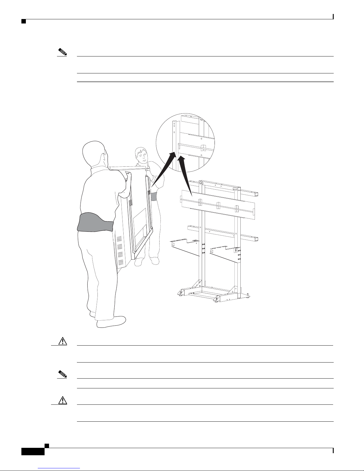
Step 1 Hang the left, center, and right Plasma displays on the Display structure crossbars.
Figure 3-1 The left, center, and right Plasma displays
Caution The edges of the Plasma displays are sharp and uncomfortable to lift with bare hands. Nonslip gloves
are recommended.
Note Make sure the Plasma display Leveling feet remain firmly seated on top of the Display shelf supports.
Caution Do not lift the display without appropriate back support, foot protection (such as steel-toed shoes), and
room to lift the display using your legs and not your back.
Cisco TelePresence System 3200
3-2
OL-14521-01
Page 27
Chapter 3 Mounting and Leveling the Plasma Displays
201111
Purpose of Leveling the Plasma displays
Warning
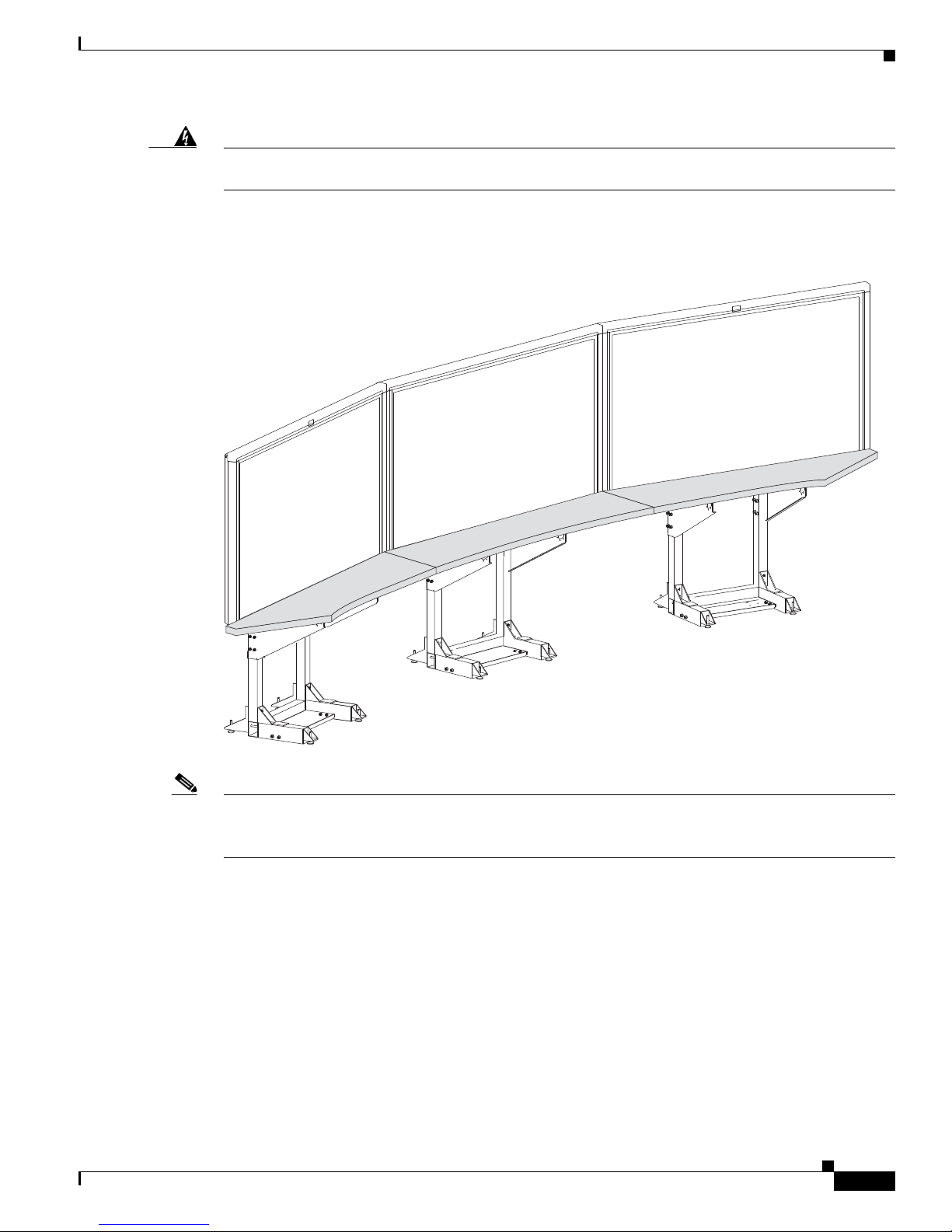
Step 2 Loosely attach the Display shelves to the Display shelf supports.
The displays are heavy and may cause injury or damage if care is not taken to support them properly
while mounting. Use caution and additional assistance as needed.
Figure 3-2 Loosely Attach the Display shelves to the Display Shelf Supports
Note The Display shelves are used in this chapter for leveling purposes only. See Chapter 4, “Building the
Display Shelf Assembly” and use the M8 x 20 mm screws in the Accessory Kit to attach the display
shelves.
Purpose of Leveling the Plasma displays
The three Plasma displays act as windows allowing a three-way view into the remote Cisco TelePresence
conference room. The Display shelf in front of each Plasma display acts as a visual bridge between the
local and remote conference rooms. In order to provide the experience of one seamless conference area,
the Display shelf must appear seamlessly integrated with the remote conference tables.
OL-14521-01
Cisco TelePresence System 3200
3-3
Page 28
Purpose of Leveling the Plasma displays
201113
Leveling Alignment Points
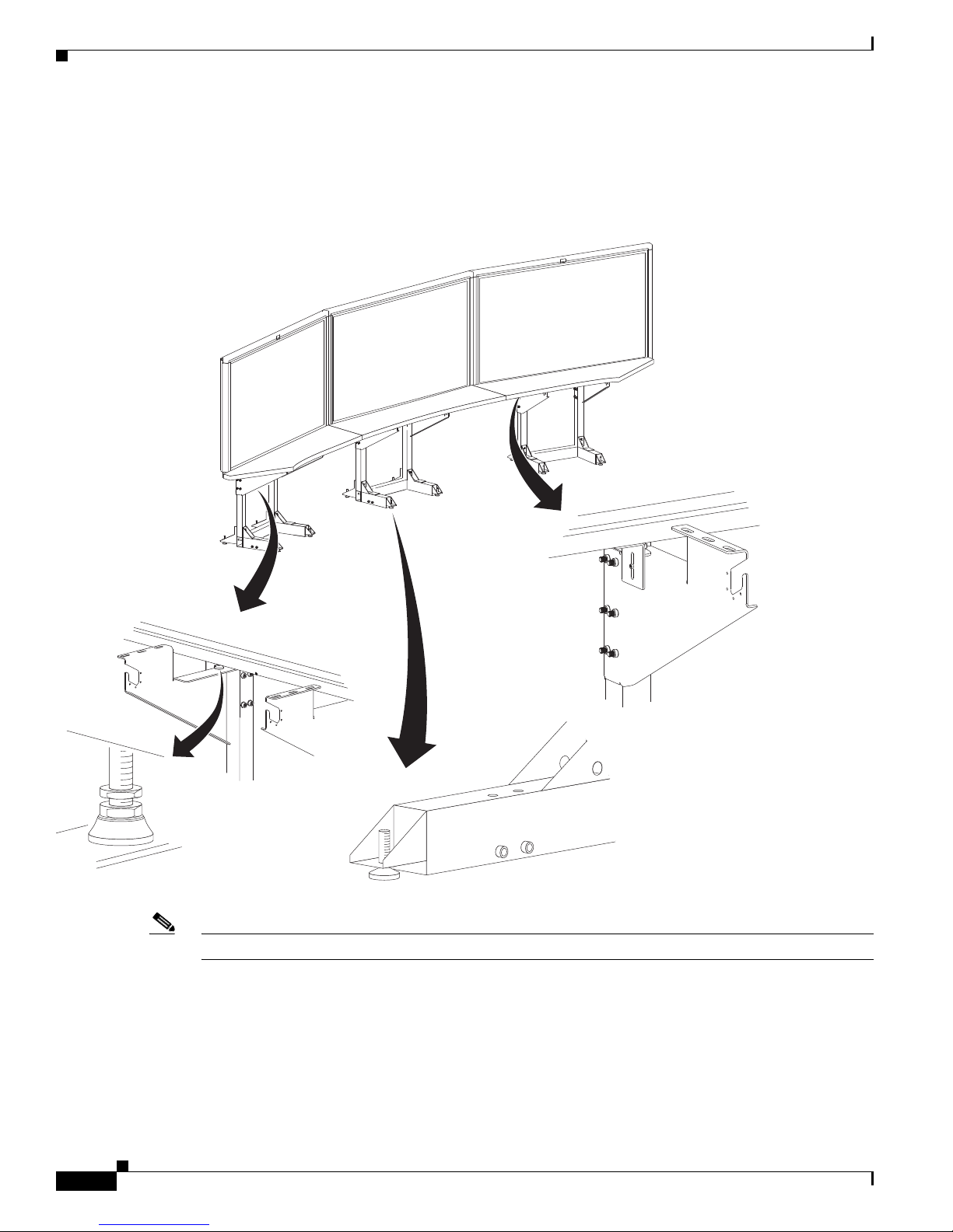
Step 3 Use the leveling alignment points to level and align the Plasma displays.
Figure 3-3 Leveling Alignment Points
Chapter 3 Mounting and Leveling the Plasma Displays
Note You can use a 5 mm hex key to adjust the display structure’s front and rear Foot Levelers.
Leveling Goals
Leveling the Display shelves and the Plasma displays, and aligning the seams of the Display shelves with
the edges of the Plasma displays ensure that images displayed from the remote conference room match
the local conference room configuration.
Cisco TelePresence System 3200
3-4
OL-14521-01
Page 29
Chapter 3 Mounting and Leveling the Plasma Displays
201114
The leveling goals illustrated in Figure 3-4 through Figure 3-8 show how to use the leveling alignment
points in Figure 3-3. You may need to perform any or all of the illustrated goals several times while
aligning and leveling the Plasma displays, and make additional adjustments later if the displays have
settled.
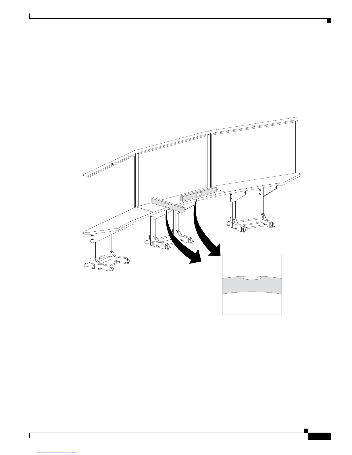
Step 4 Use the four Leveling feet on each Display structure to level the Display shelves along the X and Y axes.
Leveling the Display shelves ensures the Display structures are level. The Display structures should be
level before attempting to level the Plasma displays.
Figure 3-4 Level the Display shelves along the X and Y axes
Purpose of Leveling the Plasma displays
Step 5
The surface of the Display shelves should not obstruct any lines of resolution. Use the Plasma display
Leveling feet to raise or lower the Plasma displays and make sure all lines of resolution can be seen when
sitting at both the first and second conference tables.
OL-14521-01
Cisco TelePresence System 3200
3-5
Page 30
Purpose of Leveling the Plasma displays
Figure 3-5 Make sure no lines of resolution are blocked by the Display shelves
Chapter 3 Mounting and Leveling the Plasma Displays
Step 6
Use the Plasma display Leveling feet to level the Plasma displays along the X axis.
Use the Display tilt brackets to level the Plasma displays along the Y axis.
Tip You should level the center Plasma display first. Then align the left and right Plasma displays to the
center display.
Cisco TelePresence System 3200
3-6
OL-14521-01
Page 31

Chapter 3 Mounting and Leveling the Plasma Displays
201116
Figure 3-6 Level the Plasma displays along the X and Y axes
Purpose of Leveling the Plasma displays
Caution Do not place the level against the Plasma display screen. Place the level against the Plasma display bezel.
Step 7 Align the edges of Plasma displays
The gap between Plasma displays should be uniformly even from the top edge of the Plasma display to
the bottom edge. You should try to make the gap as small as possible.
OL-14521-01
Cisco TelePresence System 3200
3-7
Page 32

Purpose of Leveling the Plasma displays
Figure 3-7 Align the edges of Plasma displays
Chapter 3 Mounting and Leveling the Plasma Displays
Step 8
Align the seams of the Display shelves with the seams between Plasma displays.
You may need to adjust the Plasma displays left to right so the seam created between the edges of two
Plasma displays are aligned to the corresponding Display shelf seam.
Cisco TelePresence System 3200
3-8
OL-14521-01
Page 33

Chapter 3 Mounting and Leveling the Plasma Displays
Caution While moving the Plasma display to the left or right you need to make sure the Plasma display
Leveling feet remain firmly seated on top of the Display shelf supports.
Figure 3-8 Align the seams of the Display shelves with the seams between Plasma displays
Purpose of Leveling the Plasma displays
Step 9
OL-14521-01
Complete the plasma display screen setup by applying the Black Buffer strips.
Cisco TelePresence System 3200
3-9
Page 34

Purpose of Leveling the Plasma displays
201119
Figure 3-9 Apply the Black Buffer strips
Chapter 3 Mounting and Leveling the Plasma Displays
Cisco TelePresence System 3200
3-10
OL-14521-01
Page 35

CHA PTER
4
Building the Display Shelf Assembly
Revised: September 16, 2009, OL-14521-01
Parts List
Display Shelf, Type 1
Key Part Description Part Number Qty Ctn Notes
1
Display shelf section: left 700-23600-xx 1 58
2
Display shelf section: center 700-23599-xx 1 58
3
Display shelf section: right 700-23598-xx 1 58
4
Not used
5
Left accessory cabinet attachment bracket 700-23336-xx 1 19
6
Right accessory cabinet attachment bracket 700-23337-xx 1 19
7
Not used
8
Connecting plates 700-23345-xx 2 13
9
Speaker board brackets 6 46 Included with projector screen kit.
10
Splines No part number 2 58
11
Draw bolts 51-4579-xx 6 58
12
M8 x 20 mm screws 48-2273-01 1
and
13
OL-14521-01
Cisco TelePresence System 3200
4-1
Page 36

Chapter 4 Building the Display Shelf Assembly
Parts List
Accessory Cabinet
1
Accessory Cabinet, Right 700-29441-01
Kit # 69-1837-xx
2
Accessory Cabinet, Left 700-29442-01
Kit #69-1838-xx
3
Assembly Screen Supports No part number 2 Located inside of assembly cabinet.
4
M8 x 30 mm screws 69-1706-xx 14 1
1 47
1 48
These brackets are only required if
you use a Type 1 projector screen,
part number 800-28681-01. If your
installation uses the projector
screen with a product ID of
CTS3K-SCREEN and a part
number of 74-5416-01, do not
install these brackets.
Caution The shelf segments are unstable during assembly. Use caution, and support all structures as required.
Caution Some system components have metal and plastic edges with hard angles. These edges are exposed until
you complete system assembly. Use caution when you move around the system during assembly to avoid
contact with any exposed system edges.
Warning
Caution In order to prevent scratching the Display shelves, you should avoid putting any tools on the shelf
Only trained and qualified personnel should be allowed to install, replace, or service this equipment.
surfaces.
Note The directions left and right refer to the assembly as you face the Plasma displays.
Cisco TelePresence System 3200
4-2
OL-14521-01
Page 37

Chapter 4 Building the Display Shelf Assembly
12
5
3
1
12
6
205467
8
9
12
10
11
9
14
14
8
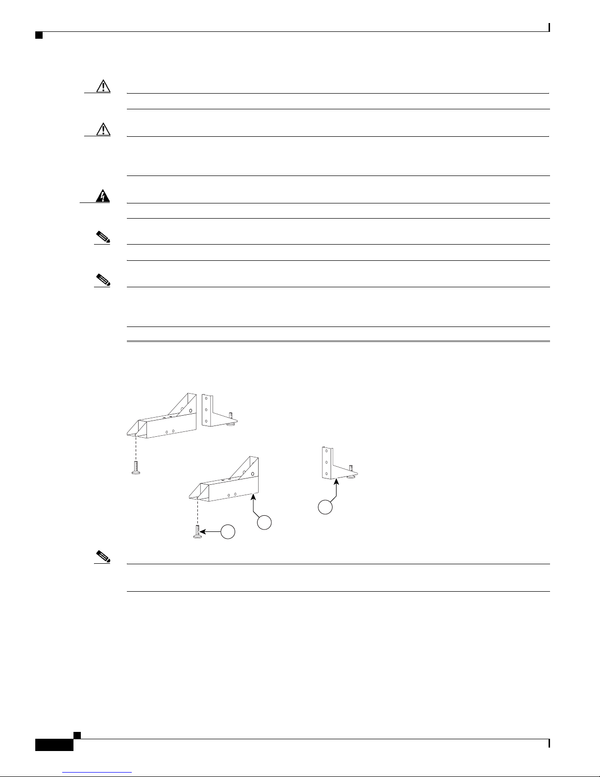
Step 1 Attach the Display shelf hardware.
Figure 4-1 Display shelf hardware
Parts List
Note The Right Accessory Cabinet attachment bracket (marked “6” in the illustration), has a central
Note This illustration describes the hardware used to attach the three Display shelves and the
rectangular hole that differentiates it from the Left Accessory Cabinet attachment bracket.
hardware used to attach additional assemblies in
Cisco TelePresence Elements.” The Display shelves should be attached individually to the
Display structures, as illustrated in Figure 4-2, Figure 4-3, and Figure 4-4.
OL-14521-01
Chapter 8, “Assembling the Remaining
Cisco TelePresence System 3200
4-3
Page 38

Parts List
201148
1
13
13
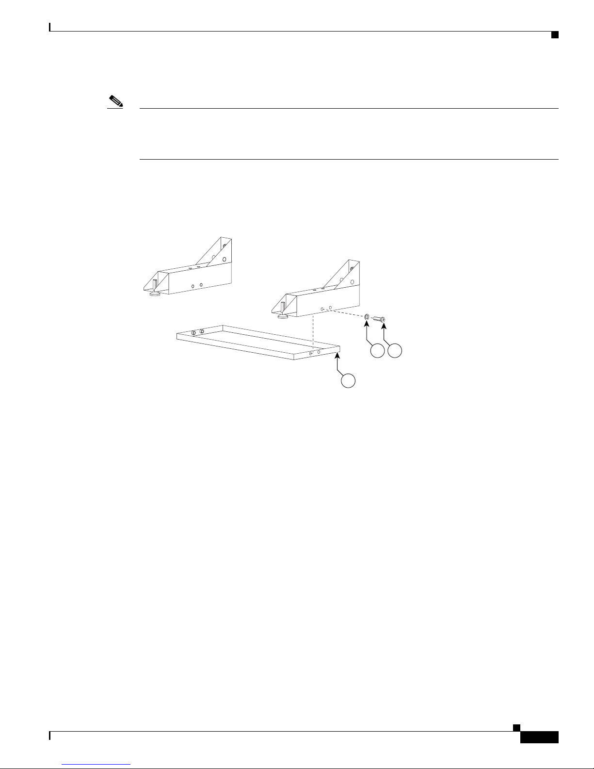
Step 2 Attach the left Display shelf.
Figure 4-2 Left Display shelf
Chapter 4 Building the Display Shelf Assembly
Cisco TelePresence System 3200
4-4
OL-14521-01
Page 39

Chapter 4 Building the Display Shelf Assembly
201149
2
13
13
Step 3 Attach the center Display shelf
Figure 4-3 Center Display shelf
Parts List
Note Refer to Figure 4-1 to see the hardware used to attach the center Display shelf to the left Display
shelf.
OL-14521-01
Cisco TelePresence System 3200
4-5
Page 40

Parts List
201150
3
13
13
Step 4 Attach the right Display shelf.
Figure 4-4 Right Display shelf
Chapter 4 Building the Display Shelf Assembly
Note Refer to Figure 4-1 to see the hardware used to attach the right Display shelf to the center
Display shelf.
Cisco TelePresence System 3200
4-6
OL-14521-01
Page 41

Chapter 4 Building the Display Shelf Assembly
204159
12
3
4
1
2
3
4
12
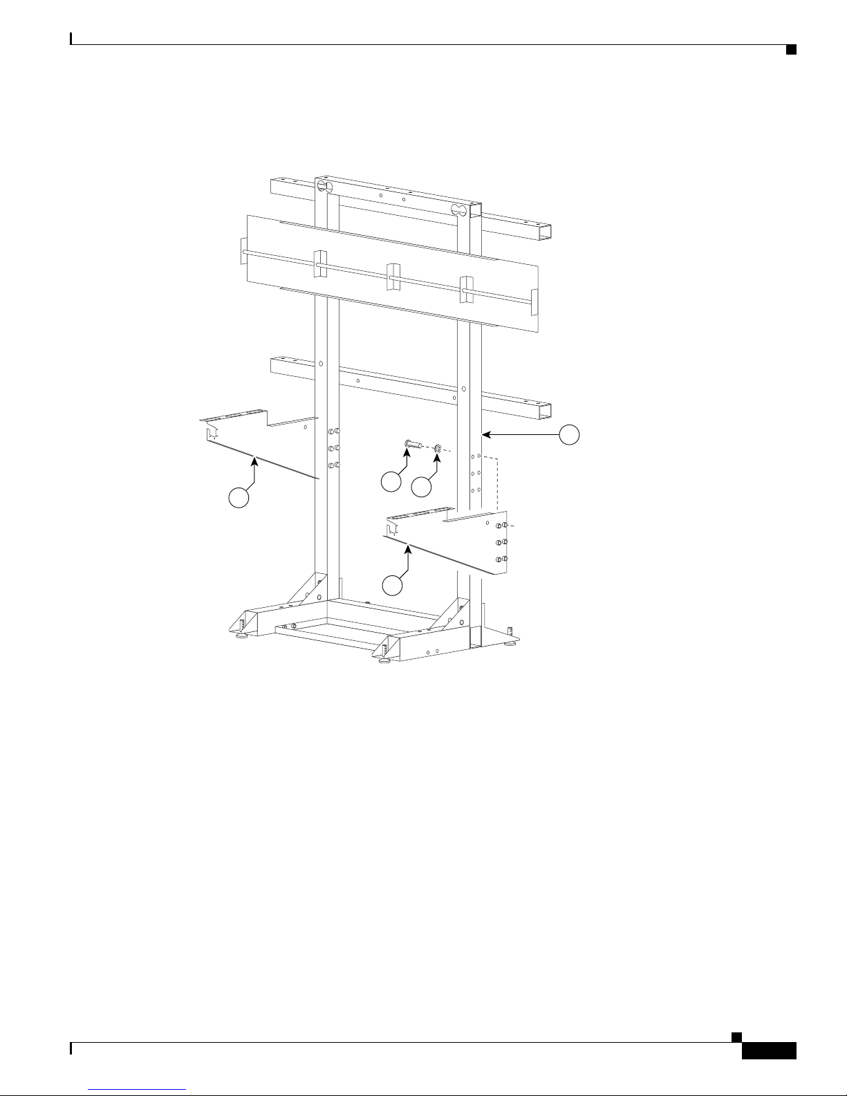
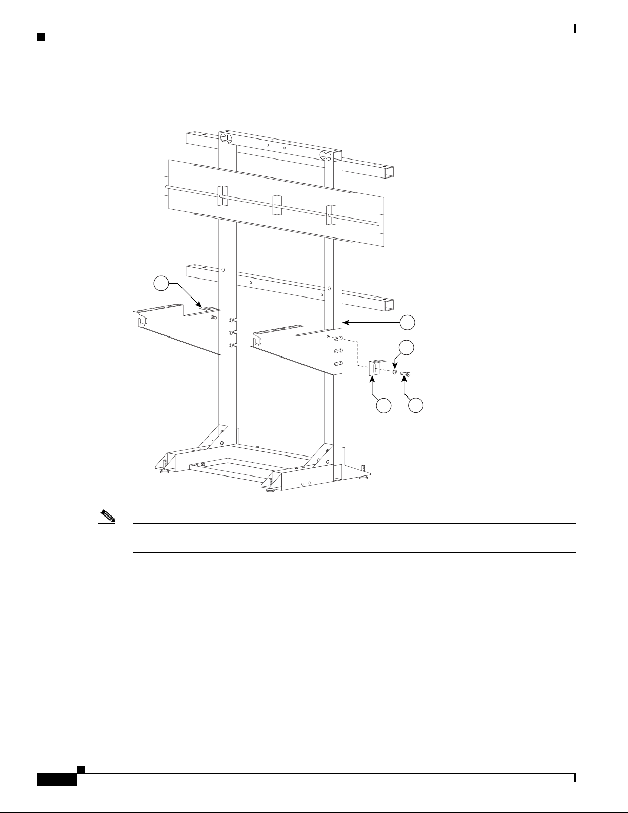
Step 5 Attach the screen supports to the accessory cabinets and position, but do not attach, the cabinets to the
left and right attachment brackets
These screen supports are only required if you use a Type 1 projector screen, part number 800-28681-01.
If your installation uses the projector screen with a product ID of CTS3K-SCREEN and a part number
of 74-5416-01, do not install these brackets.
Figure 4-5 Accessory Cabinet
Parts List
Note One wall of the left Accessory cabinet was removed from this illustration for clarity.
Note Before you attach the Accessory cabinets to the brackets, use them as supports while assembling
the table segments in Chapter 6, “Building the First Row Table Assembly.”
OL-14521-01
Cisco TelePresence System 3200
4-7
Page 42

Parts List
Chapter 4 Building the Display Shelf Assembly
Cisco TelePresence System 3200
4-8
OL-14521-01
Page 43

CHA PTER
Building the Lighting Assembly
Revised: September 16, 2009, OL-14521-01
Parts List
Key Part Description Part Number Qty Ctn Notes
1
Lighting support brackets 700-23749-xx 6 49
2
Support struts 700-23752-xx 6 49
3
End structure brackets 700-23750-xx 4 49
4
Plastic diffuser panel: center 700-23745-xx 1 49
5
Plastic diffuser panel: ends 700-23746-xx 2 49
6
Plastic diffuser panel: top right 700-23747-xx 1 49
7
Plastic diffuser panel: top left 700-23748-xx 1 49
8
L-bracket 700-23899-xx 4 49
9
Metal trim panel: center left 700-24126-xx 1 49
10
Metal trim panel: top side 700-23897-xx 2 49
11
Metal trim panel: end 700-23898-xx 2 49
12
Metal trim panel: center right 700-23896-xx 1 49
13
Reflector bottom tray: center 700-23826-xx 1 49
14
Reflector bottom tray: left side top 700-23827-02 1 49
15
Reflector bottom: left end 700-23828-02 1 49
16
Reflector bottom spacer 700-24152-xx 2 49
17
Reflector top: center 700-23731-xx 1 49
18
Reflector top: top side 700-23734-xx 2 49
19
Reflector top: end 700-23735-xx 2 49
20
Reflector transition piece: left 700-23756-xx 1 49
21
Reflector transition piece: right 700-23757-xx 1 49
22
Reflector transition piece: corner 700-23758-xx 2 49
5
OL-14521-01
Cisco TelePresence System 3200
5-1
Page 44

Chapter 5 Building the Lighting Assembly
Parts List
Key Part Description Part Number Qty Ctn Notes
23
Light “cup” bracket 700-23737-xx 2 43
24
5-foot center light fixture 74-5361-xx
CTS-LT-FX5FT-GN
Kit #95-8932-xx
25
4-foot side light fixture 74-5362-xx
CTS-LT-FX5FT-GN
Kit #95-8932-xx
26
M8 x 70 mm screws 48-2274-xx 10 1
27
M8 x 16 mm pan head screw, white 48-2432-xx 1
28
M8 x 20 mm flat head screw, white 48-2433-xx 10 49
29
Diffuser Panel braces / H-clips 700-25050-xx 2 49
30
Compliance sticker for plasma display 47-21525-xx 1 1
31
M8 x 16 mm pan head screw, black 48-2430-xx 2 1
32
Reflector bottom tray: right side top 700-27762-xx 1 49
33
Reflector bottom: right end 700-27763-xx 1 49
Touch-up paint, white 74-5247-xx 1 1 Use this paint on the light reflectors to fix
331See “Appendix B: Region- and
Country-Specific Equipment” for
Europe- and Japan-specific lighting
fixtures.
230, 31See “Appendix B: Region- and
Country-Specific Equipment” for
Europe- and Japan-specific lighting
fixtures.
any minor cosmetic issues caused by
shipping and handling.
Warning
Caution Metal and plastic edges can be sharp. Cisco recommends you wear safety gloves and safety glasses when
Only trained and qualified personnel should be allowed to install, replace, or service this equipment.
attaching the lighting assembly.
Caution Some system components have metal and plastic edges with hard angles. These edges are exposed until
you complete system assembly. Use caution when you move around the system during assembly to avoid
contact with any exposed system edges.
Note The directions left and right refer to the assembly as you face the Plasma displays.
Cisco TelePresence System 3200
5-2
OL-14521-01
Page 45

Chapter 5 Building the Lighting Assembly
Step 1 Assemble the six Support struts and six Lighting Support brackets.
Figure 5-1 Support struts and Lighting Support brackets
31
27
Parts List
1
2
201125
OL-14521-01
Cisco TelePresence System 3200
5-3
Page 46

Parts List
2
1
31
31
201126
Chapter 5 Building the Lighting Assembly
Step 2 Attach the left and right outer Support brackets (from Figure 5-1) to the horizontal bar on the left and
right Display structures.
Figure 5-2 Left and Right outer Support brackets (from Figure 5-1)
Note Use any of the six brackets that you assembled in Step 1. There is no physical difference between
the outer and inner Support brackets in Figure 5-1.
Cisco TelePresence System 3200
5-4
OL-14521-01
Page 47

Chapter 5 Building the Lighting Assembly
201127
31
2
1
26
Step 3 Attach the four inner Support brackets to the Support crossbars.
Figure 5-3 Four inner Support brackets (from Figure 5-1)
Parts List
Note Use any of the six brackets that you assembled in Step 1. There is no physical difference between
the outer and inner Support brackets in Figure 5-1.
OL-14521-01
Cisco TelePresence System 3200
5-5
Page 48

Parts List
201128
3
31
31
Chapter 5 Building the Lighting Assembly
Step 4 Attach the four End structure brackets to the ends of the Support crossbars.
Figure 5-4 Four End structure brackets
Cisco TelePresence System 3200
5-6
OL-14521-01
Page 49

Chapter 5 Building the Lighting Assembly
201129
27
32
13
27
14
Step 5 Attach the three Reflector bottom trays to the Support brackets.
Figure 5-5 Three Reflector bottom trays
Parts List
OL-14521-01
Cisco TelePresence System 3200
5-7
Page 50

Parts List
201130
13
14
16
27
Step 6 Attach the two Reflector bottom spacers to join the three Reflector bottom trays.
Figure 5-6 Two Reflector bottom spacers
Chapter 5 Building the Lighting Assembly
Cisco TelePresence System 3200
5-8
OL-14521-01
Page 51

Chapter 5 Building the Lighting Assembly
27
15
33
3
27
30
Step 7 Attach the left and right (vertical) Reflector Bottom ends to the End Structure brackets and attach the
compliance sticker to the left reflector bottom end.
Figure 5-7 Left and Right (vertical) Reflector Bottom ends
Parts List
OL-14521-01
Cisco TelePresence System 3200
5-9
Page 52

Parts List
232715
201132
Step 8 Attach the Light Cup bracket to the left and right (vertical) Reflector Bottom ends.
Figure 5-8 Light Cup bracket
Chapter 5 Building the Lighting Assembly
Cisco TelePresence System 3200
5-10
OL-14521-01
Page 53

Chapter 5 Building the Lighting Assembly
24
24
27
13
2432
Step 9 Attach the three 5-foot Light fixtures inside the Reflector bottoms.
Figure 5-9 Three 5-foot Light fixtures
Parts List
OL-14521-01
Cisco TelePresence System 3200
5-11
Page 54

Parts List
27
25
201134
Step 10 Attach the left and right 4-foot Side Light fixtures to the left and right (vertical) Reflector Bottom ends.
Figure 5-10 Left and Right 4-foot Side Light fixtures
Chapter 5 Building the Lighting Assembly
Note The power cords for the Side Light fixtures should extend from the top through the Light Cup bracket
(Figure 5-8).
Cisco TelePresence System 3200
5-12
OL-14521-01
Page 55

Chapter 5 Building the Lighting Assembly
12
9
201135
31
Step 11 Attach the two center Metal Trim panels.
Figure 5-11 Two center Metal Trim panels
Parts List
OL-14521-01
Cisco TelePresence System 3200
5-13
Page 56

Parts List
34
10
31
201136
Step 12 Attach the two side Metal Trim panels.
Figure 5-12 Two side Metal Trim panels
Chapter 5 Building the Lighting Assembly
Cisco TelePresence System 3200
5-14
OL-14521-01
Page 57

Chapter 5 Building the Lighting Assembly
201137
4
31
Step 13 Attach the center Plastic Diffuser panel.
Figure 5-13 Center Plastic Diffuser panel
Parts List
OL-14521-01
Cisco TelePresence System 3200
5-15
Page 58

Parts List
201138
7
6
31
Step 14 Attach the left and right plastic diffuser panels. Before fully tightening the screws, adjust the panels to
the left or right to ensure that the spacing between the diffuser panels are even.
Figure 5-14 Left and Right Plastic Diffuser panels
Chapter 5 Building the Lighting Assembly
Note The rounded corners of the left and right plastic diffuser panels point outward.
Cisco TelePresence System 3200
5-16
OL-14521-01
Page 59

Chapter 5 Building the Lighting Assembly
5
31
8
Step 15 Attach the four L-brackets to the two (vertical) end Plastic Diffuser panels.
Figure 5-15 Four L-brackets
Parts List
OL-14521-01
Cisco TelePresence System 3200
5-17
Page 60

Parts List
5
31
201140
3
Step 16 Attach the two (vertical) Plastic Diffuser panels to the End Structure brackets.
Figure 5-16 Two (vertical) Plastic Diffuser panels
Chapter 5 Building the Lighting Assembly
Cisco TelePresence System 3200
5-18
OL-14521-01
Page 61

Chapter 5 Building the Lighting Assembly
201202
13
29
Step 17 Slide the Plastic Diffuser Panel brace between the end (vertical) Plastic Diffuser panel and the left and
right Plastic Diffuser panels.
Figure 5-17 Plastic Diffuser Panel brace
Parts List
Note If a diffuser becomes scratched, use a black felt-tip permanent marker to cover the imperfection.
OL-14521-01
Cisco TelePresence System 3200
5-19
Page 62

Parts List
17
13
27
201141
Step 18 Attach the center Reflector top to the center Reflector bottom.
Figure 5-18 Center Reflector top
Chapter 5 Building the Lighting Assembly
Note Do not tighten screws until completing Step 22.
Cisco TelePresence System 3200
5-20
OL-14521-01
Page 63

Chapter 5 Building the Lighting Assembly
18
18
14
32
201142
27
Step 19 Attach the left and right Reflector tops to the left and right Reflector bottoms.
Figure 5-19 Left and Right Reflector tops
Parts List
Note Do not tighten screws until completing Step 22.
OL-14521-01
Cisco TelePresence System 3200
5-21
Page 64

Parts List
201143
21
28
20
27
18
17
Step 20 Join the left, center, and right Reflector tops with the left and right Reflector Transition pieces.
Figure 5-20 Left and Right Reflector Transition pieces
Chapter 5 Building the Lighting Assembly
Note Do not tighten screws until completing Step 22.
Cisco TelePresence System 3200
5-22
OL-14521-01
Page 65

Chapter 5 Building the Lighting Assembly
15
27
19
33 27
19
Step 21 Attach the left and right (vertical) Reflector ends to the left and right (vertical) Reflector Bottom ends.
Figure 5-21 Left and Right (vertical) Reflector ends
Parts List
Note Do not tighten screws until completing Step 22.
OL-14521-01
Cisco TelePresence System 3200
5-23
Page 66

Parts List
22
18
18
22
28
27
Step 22 Attach the left and right corner Reflector Transition pieces to the Reflector tops.
Figure 5-22 Left and Right corner Reflector Transition pieces
Chapter 5 Building the Lighting Assembly
Note Tighten all screws from Figure 5-18 through Figure 5-22. The goal is to ensure the reflector pieces form
a “seamless hood” around the lighting assembly.
Cisco TelePresence System 3200
5-24
OL-14521-01
Page 67

Chapter 5 Building the Lighting Assembly
201146
11
5
27
11
Step 23 Attach the two Metal Trim panels to the L-brackets attached to the two (vertical) Plastic Diffuser panels.
Figure 5-23 Two Metal Trim panels
Parts List
Note Install the codecs before you continue to the next chapter. See Step 5 through Step 8 in Chapter 8,
“Assembling the Remaining Cisco TelePresence Elements” to install the codecs; then see Chapter 4,
“Building the Display Shelf Assembly” to continue the installation.
Note These Metal Trim panels cover the access opening used to route cables. You may not want to attach these
Metal Trim panels until you complete the cable routing in Chapter 9, “Routing Power and Signal
Cables.”
OL-14521-01
Cisco TelePresence System 3200
5-25
Page 68

Parts List
Chapter 5 Building the Lighting Assembly
Tip If required, use the white touch-up paint on the light reflectors to fix any minor cosmetic issues caused
by assembly, shipping, or handling.
Cisco TelePresence System 3200
5-26
OL-14521-01
Page 69

CHA PTER
Building the First Row Table Assembly
Revised: October 29, 2009, OL-14521-01
Parts List
Key Part Description Part Number Qty Ctn Notes
1
Tabletop leg base 800-28454-xx
800-28628-xx (left)
2
Metal packaging brace 700-24275-xx 4 41-
3
Molded foam bumper 800-28625-xx 4 41-
4
Tabletop section: right wing 95-9690-xx
Kit # 74-5302-xx
5
Tabletop section: Center right 95-9687-xx
Kit # 74-5300-xx
6
Tabletop section: center 95-9686-xx
Kit # 74-5299-xx
7
Tabletop section: Center left 95-9689-xx
Kit # 74-5301-xx
8
Tabletop section: left door 95-9691-xx
Kit # 74-5303-xx
9
Connecting plate 700-27292-xx 6 50
10
Draw bolt No part number 12 1
11
Left tabletop hinge 51-4539-xx 1 1
12
Spline No part number 5 1
13
“Please close” label 56-15736-xx 1
3
5254
1
52
43,
57
43,
57
1 58
1 58
1 58
1 58
1 58
6
OL-14521-01
Cisco TelePresence System 3200
6-1
Page 70

Chapter 6 Building the First Row Table Assembly
Parts List
Key Part Description Part Number Qty Ctn Notes
14
M8 x 20 mm screws, black 48-2273-01 30 1
and
15
16
Phillips head wood screws 8 1 Included with Left tabletop hinge.
17
Plate for left side table 1 Installs on the side closest to the table
door.
18
I/O blank: large 700-23806-xx 1
19
I/O blank: small 700-23807-xx 6 1
20
I/O modules: power/Ethernet 74-xxxx-xx 6 1 Part number changes per country. Refer
to
“Appendix B: Region- and
Country-Specific Equipment” for part
number.
21
I/O Module Cover plate 700-23305-xx 50-
54
22
10 m Cat6 Ethernet cable 37-0901-xx 6 1
23
3 m Jumper cord 37-0833-xx 9 1
24
M4 nuts 49-0326 20 1
25
M4 x 12 mm screws, black 48-2426-xx
Kit # 69-1878-xx
26
Microphone 74-4743-xx 3 1
27
M4 x 30 mm screws 1 Included in Microphone kit.
28
M4 washers 1 Included in Microphone kit.
29
Table hinge safety hinge To b e provide d 1
30
M8 x 20 mm screws 48-2273-01 1
Privacy Panel Assembly
1
Privacy panel: Center left 700-23333-xx 1 34
2
Privacy panel: center 700-23334-xx 1 34
3
Privacy panel: Center right 700-23332-xx 1 34
4
Privacy panel: right wing 700-23362-xx 1 14
5
M8 x 20 mm screws 48-2273-xx 1
10 1
Caution The table segments are unstable during assembly. Use caution, and support all structures as required.
Caution Some system components have metal and plastic edges with hard angles. These edges are exposed until
you complete system assembly. Use caution when you move around the system during assembly to avoid
contact with any exposed system edges.
Warning
Cisco TelePresence System 3200
Only trained and qualified personnel should be allowed to install, replace, or service this equipment.
6-2
OL-14521-01
Page 71

Chapter 6 Building the First Row Table Assembly
201152
3
2
Caution Table elements are heavy, and metal edges can be very sharp. Protect your hands and eyes from injury
by wearing safety gloves and glasses.
Caution In order to prevent scratching the Display shelves, you should avoid putting any tools on the shelf
surfaces.
Note The directions left and right refer to the assembly as you face it from the front.
Parts List
Warning
Table legs are unstable until they are fully attached to the tabletop. Do not use unattached table legs
as tabletop supports while you attach tabletop segments. They can fall and cause injury or damage.
Cisco suggests you use the accessory cabinets to support and stabilize the table segments as you
install them.
Step 1 Remove the Metal packaging braces from the Molded foam bumpers.
Figure 6-1 Metal packaging braces and their Molded foam bumpers
Step 2 Assemble the four Molded foam bumpers and the four Table leg bases.
OL-14521-01
Cisco TelePresence System 3200
6-3
Page 72

Parts List
201153
3
15
1
Figure 6-2 Four Molded foam bumpers and the four Table leg bases
Chapter 6 Building the First Row Table Assembly
Note The leg base with only one top right attachment bracket is the left most table leg (see
Figure 6-12). The other three legs each have two attachment brackets.
Step 3 Assemble the I/O modules for the outside left and outside right molded foam bumpers.
The outside left and outside right molded foam bumpers only have one I/O module each. The inner
molded foam bumpers have two (see
Cisco TelePresence System 3200
6-4
Figure 6-4).
OL-14521-01
Page 73

Chapter 6 Building the First Row Table Assembly
Figure 6-3 Foam Bumper Assembly
18
25
Parts List
21
22 23 24
19
20
Note Steps for routing the Ethernet and power cables are in Chapter 9, “Routing Power and Signal Cables.”
Note The flange on the I/O module cover place is wider on the bottom than on the top.
Step 4 Assemble the I/O modules for the inner molded foam bumpers.
204176
OL-14521-01
Cisco TelePresence System 3200
6-5
Page 74

Parts List
204178
21
20
19
25
22 23 24
Chapter 6 Building the First Row Table Assembly
Figure 6-4 Foam Bumper Assembly
Note Steps for routing the Ethernet and power cables are in Chapter 9, “Routing Power and Signal Cables.”
Note The flange on the I/O module cover place is wider on the bottom than on the top.
Step 5 Attach the right wing tabletop section to the right Accessory Cabinet bracket.
Cisco TelePresence System 3200
6-6
OL-14521-01
Page 75

Chapter 6 Building the First Row Table Assembly
201154
15
4
Figure 6-5 Right Wing Tabletop Section
Parts List
Step 6 Attach the right Table segment.
a. Make sure you tighten the draw bolt evenly on both sides.
b. While a draw bolt is being tightened, hold the table edges together to avoid damage to the draw bolt
or the table segment.
c. Tighten the draw bolt so the two table segments are connected snugly.
d. While one person is tightening the draw bolt from below, it is important for the support person to
maintain the alignment of the table segment edges.
OL-14521-01
Cisco TelePresence System 3200
6-7
Page 76

Parts List
5
12
4
204138
10
30
9
Figure 6-6 Right Table segment
Chapter 6 Building the First Row Table Assembly
Note The splines have different lengths. Use a spline that is slightly smaller than the slot in the table top.
Step 7 Attach the right most Table Leg.
Cisco TelePresence System 3200
6-8
OL-14521-01
Page 77

Chapter 6 Building the First Row Table Assembly
15
15
204140
Figure 6-7 right Most Table Leg
Parts List
Step 8 Attach the center Table segment.
a. Make sure you tighten the draw bolt evenly on both sides.
b. While a draw bolt is being tightened, hold the table edges together to avoid damage to the draw bolt
or the table segment.
c. Tighten the draw bolts so the two table segments are connected snugly.
OL-14521-01
Cisco TelePresence System 3200
6-9
Page 78

Parts List
6
5
12
204139
10
d. While one person is tightening the draw bolt from below, it is important for the support person to
maintain the alignment of the table segment edges.
Figure 6-8 Center Table segment
Chapter 6 Building the First Row Table Assembly
6-10
Note The splines have different lengths. Use a spline that is slightly smaller than the slot in the table top.
Step 9 Attach the right center Table leg.
Cisco TelePresence System 3200
OL-14521-01
Page 79

Chapter 6 Building the First Row Table Assembly
15
15
Figure 6-9 right center Table leg
Parts List
Step 10 Attach the left Table segment.
a. The draw bolts have two halves that screw into a center piece.
OL-14521-01
Cisco TelePresence System 3200
6-11
Page 80

Parts List
204142
7
6
12
10
b. While a draw bolt is being tightened, hold the table edges together to avoid damage to the draw bolt
or the table segment.
c. Tighten the draw bolts so the two table segments are connected snugly.
d. While one person is tightening the draw bolts from below, it is important for the support person to
maintain the alignment of the table segment edges.
Figure 6-10 Left Table segment
Chapter 6 Building the First Row Table Assembly
Note The splines have different lengths. Use a spline that is slightly smaller than the slot in the table top.
Step 11 Attach the left center Table leg.
Cisco TelePresence System 3200
6-12
OL-14521-01
Page 81

Chapter 6 Building the First Row Table Assembly
15
15
Figure 6-11 Left center Table leg
Parts List
Step 12 Attach the left most Table leg.
OL-14521-01
Cisco TelePresence System 3200
6-13
Page 82

Parts List
15
15
204144
Figure 6-12 left Most Table Leg
Chapter 6 Building the First Row Table Assembly
Step 13 Attach one microphone to the left, right and center first row table segments.
The center microphone cable for the first row table must be seated in the cable channel on the underside
of the center table segment in order to properly install the projector bracket. You can use tape to secure
it in place.
Cisco TelePresence System 3200
6-14
OL-14521-01
Page 83

Chapter 6 Building the First Row Table Assembly
204177
2728
26
Note Steps for routing and connecting the microphone extension cables from the audio/video extension unit
and codec to the microphones are in Chapter 9, “Routing Power and Signal Cables.”
Figure 6-13 Microphone Assembly
Parts List
Step 14 Attach the table door to the tabletop sections and attach the “please close” label to the underside of the
table door.
OL-14521-01
Cisco TelePresence System 3200
6-15
Page 84

Parts List
204145
11
15
29
16
3017
Figure 6-14 Left connecting Tabletop section
Chapter 6 Building the First Row Table Assembly
Step 15 Attach the center Privacy panel.
Cisco TelePresence System 3200
6-16
OL-14521-01
Page 85

Chapter 6 Building the First Row Table Assembly
2
5
Rotated
for clarity
201171
Figure 6-15 Privacy Panel Assembly
Parts List
Step 16 Attach the left Privacy panel.
OL-14521-01
Cisco TelePresence System 3200
6-17
Page 86

Parts List
1
5
Rotated
for clarity
Figure 6-16 Privacy Panel Assembly
Chapter 6 Building the First Row Table Assembly
Step 17 Attach the right Privacy panel.
Cisco TelePresence System 3200
6-18
OL-14521-01
Page 87

Chapter 6 Building the First Row Table Assembly
3
5
201173
Rotated
for clarity
Figure 6-17 Privacy Panel Assembly
Parts List
Step 18 Attach the right wing Privacy panel.
OL-14521-01
Cisco TelePresence System 3200
6-19
Page 88

Parts List
45
201174
Chapter 6 Building the First Row Table Assembly
Figure 6-18 Privacy Panel Assembly
Cisco TelePresence System 3200
6-20
OL-14521-01
Page 89

CHA PTER
Building the Second Row Table Assembly
Revised: October 29, 2009, OL-14521-01
Table Numbering Information Used in This Chapter
The table tops and privacy panels are numbered to assist you in installation. Your tabletops and privacy
panels use one of the following numbering schemes:
• Tabletops are numbered section 1 to section 7. The numbering scheme counts tabletop sections
starting from the center of the assembly. There are two tabletops that use section 5; if the two
sections are differentiated, they are labeled “section 5 right” and “section 5 left”.
Note The directions left and right refer to the assembly as you face the displays.
• Tabletops are numbered section 1 to section 8. The numbering scheme counts tabletop sections from
the right to the left.
7
Use the numbering scheme that is printed you your tabletops and privacy panels to perform this
procedure. Both methods of numbering are listed in this chapter and are included in the figures and
assembly steps.
Parts List
Key Part Description Part Number Qty Ctn Notes
1
Tabletop leg base 800-28454-xx 7 52-
54
2
Metal packaging brace 700-24275-xx 7 41-
43,
57
3
Molded foam bumper 800-28625-xx 7 41-
43,
57
4
Gutter and privacy panel support bracket,
type 1
OL-14521-01
700-27280-xx 2 50
Cisco TelePresence System 3200
7-1
Page 90

Chapter 7 Building the Second Row Table Assembly
Parts List
Key Part Description Part Number Qty Ctn Notes
5
Gutter and privacy panel support bracket,
type 2
6
Gutter panel, section 1 (section 5) 800-31126-xx 1 50
7
Gutter panel, section 2 (section 4) 800-31129-xx 1 50
8
Gutter panel, section 3 (section 6) 800-31131-xx 1 50
9
Gutter panel, section 4 (section 3) 800-31133-xx 1 50
10
Gutter panel, section 5 (sections 2 and 7) 800-31124-xx 2 50
11
Privacy panel hanger 700-27311-xx 14 50
12
Floating bracket, type 1 700-27282-xx 2 50
13
Floating bracket, type 2 700-27281-xx 2 50
14
Tabletop: section 1 (section 5) 95-9995-01
15
Tabletop: section 2 (section 4) 95-10096-01
16
Tabletop: section 3 (section 6) 95-10097-01
17
Tabletop: section 4 (section 3) 95-10098-01
18
Tabletop: section 5 (sections 2 and 7) 95-9994-01
19
Tabletop end, left (section 6) 95-10099-01
20
Tabletop end, right (section 7) 95-10100-01
21
Tabletop end brace 700-27413-xx 2 50
22
Privacy panel alignment bracket,
section
1 (section 5)
23
Privacy panel alignment bracket,
section
2 (section 4)
24
Privacy panel alignment bracket,
section
3 (section 6)
25
Privacy panel alignment bracket,
section
4 (section 3)
26
Privacy panel alignment bracket,
section
5 (sections 2 and 7)
27
Privacy panel, section 1 (section 5) 800-31112-xx 1 50
28
Privacy panel, section 2 (section 4) 800-31116-xx 1 50
29
Privacy panel, section 3 (section 6) 800-31117-xx 1 50
30
Privacy panel, section 4 (section 3) 800-31119-xx 1 50
700-27279-xx 5 50
1 26
Kit # 74-5565-01
1 26
Kit # 74-5600-01
1 26
Kit # 74-5601-01
1 26
Kit # 74-5602-01
2 26 Some tabletop sections are marked
Kit # 74-5562
1 26
Kit # 74-5603-01
1 26
Kit # 74-5604
700-27275-xx 1 50
700-27276-xx 1 50
700-27277-xx 1 50
700-27278-xx 1 50
700-27274-xx 2 50
“5
left” and “5 right”; install the sections
so that the tabletop grain is correctly
matched.
Cisco TelePresence System 3200
7-2
OL-14521-01
Page 91

Chapter 7 Building the Second Row Table Assembly
Key Part Description Part Number Qty Ctn Notes
31
Privacy panel, section 5 (sections 2
and
7)
32
Privacy Panel, left end section 6
(section
33
Privacy Panel, right end section 7
8)
(section 1)
34
Tabletop attachment plate, metal 700-27292-xx 2 50
35
M8 x 16 mm screws 48-2430-01 58 21
36
M8 x 2.5mm shoulder screws 69-1880-01
37
M8 x 16 mm screws 48-2430-01 24 21
38
Screw, 8 x 50 mm, with plastic knob 69-1877-01
39
Draw bolt No part number 14 1
40
Spline No part number 5 1 Either splines or wooden biscuits (callout
41
Cable Cover for right end privacy panel 700-27312-01 1 50
42
Velcro attachments for cable guide No part number 2 Included with cable cover
43
I/O blank: large 700-23806-01 2 1
44
I/O blank: small 700-23807-01 14 1
45
I/O modules: power/Ethernet 74-xxxx-xx 12 1 Part number changes per country. Refer
46
I/O Module Cover plate 700-23305-01 7 50-
47
Cat6 Ethernet cord 37-0887-02 (3M)
48
3 m Jumper cord 37-0833-01 9 1
49
M4 nuts 49-0326 20 1
50
M4 x 12 mm screws, black 48-2426-01 10 1
51
Microphone 74-4743-01 6 1
52
M4 x 30 mm screws 1 Included in Microphone kit.
53
M4 washers 1 Included in Microphone kit.
54
Power distribution units 74-4787-01 2 1 Chapter 7, 8
55
Screws To b e pr o v id e d 1 1
56
M8 shoulder screws for Floating
Brackets
800-31121-xx 2 50
800-31123-xx 1 50
800-31122-xx 1 50
30 21
48-2437-01
15 21
48-2298-01
54
1
1
37-0901-01 (10M)
37-0965-01 (12M)
69-1880-01
8
3
28 21
48-2437-01
number 57) are supplied with the table
sections; use either the splines or the
biscuits to join the table sections.
to
“Appendix B: Region- and
Country-Specific Equipment” for part
number.
Parts List
OL-14521-01
Cisco TelePresence System 3200
7-3
Page 92

Chapter 7 Building the Second Row Table Assembly
Parts List
Key Part Description Part Number Qty Ctn Notes
57
Wooden table joiner biscuits 69-1880-01
48-2437-01
Microphone extension cords, 9.5M 37-0931-01 6 1 Attach these cords to the microphone
Touch-up paint, dark gray 79-2269-01 1 1 Use this to cover any imperfections for
Caution The table segments are unstable during assembly. Use caution, and support all structures as required.
Caution Some system components have metal and plastic edges with hard angles. These edges are exposed until
you complete system assembly. Use caution when you move around the system during assembly to avoid
contact with any exposed system edges.
28 21 Either splines (callout number 40) or
wooden biscuits are supplied with the
table sections; use either the splines or
the biscuits to join the table sections.
cables to reach the codec and audio/video
extension unit.
the privacy panel that are caused by
assembly, shipping or handling.
Warning
Caution Table elements are heavy, and metal edges can be very sharp. Protect your hands and eyes from injury
Only trained and qualified personnel should be allowed to install, replace, or service this equipment.
by wearing safety gloves and glasses.
Caution In order to prevent scratching the table tops, you should avoid putting any tools on the shelf surfaces.
Note The directions left and right refer to the assembly as you face it from the front.
Warning
Table legs are unstable until they are fully attached to the tabletop. Do not use unattached table legs
as tabletop supports while you attach tabletop segments. They can fall and cause injury or damage.
Cisco suggests you use the accessory cabinets to support and stabilize the table segments as you
install them.
Step 1 Remove the Metal packaging braces from the Molded foam bumpers.
Cisco TelePresence System 3200
7-4
OL-14521-01
Page 93

Chapter 7 Building the Second Row Table Assembly
201152
3
2
Figure 7-1 Metal packaging braces and their Molded foam bumpers
Parts List
Step 2 Assemble the seven Molded foam bumpers and the seven Table leg bases.
OL-14521-01
Cisco TelePresence System 3200
7-5
Page 94

Parts List
204149
3
37
1
Figure 7-2 Four Molded foam bumpers and the four Table leg bases
Chapter 7 Building the Second Row Table Assembly
Step 3 Attach the first set of support brackets for the gutter and privacy panel to the table legs.
Note Note the table layout. Each section is numbered as shown in Figure 7-3. Each cable gutter and privacy
panel is different. The numbering for the cable gutters and privacy panels correspond to the numbering
for the table top.
Tip When you attach the support brackets, it can be helpful to turn the table leg upside-down.
Cisco TelePresence System 3200
7-6
OL-14521-01
Page 95

Chapter 7 Building the Second Row Table Assembly
4
4
35
35
204101
3(6)
5(7)
6676
5(2)
7
4(3)
1(5)
2(4)
7(1)
6(8)
Figure 7-3 Gutter and Privacy Panel Support Brackets, Type 1
Parts List
Step 4 Attach the second set of five support brackets to the table legs.
OL-14521-01
Cisco TelePresence System 3200
7-7
Page 96

Parts List
35
5
5
204102
5
35
35
35
35
5
5
3(6)
5(7)
6676
5(2)
7
4(3)
1(5)
2(4)
7(1)
6(8)
Figure 7-4 Gutter and Privacy Panel Support Brackets, Type 2
Chapter 7 Building the Second Row Table Assembly
Step 5 While one or more assistants keep the table legs steady, attach the section 1 (section 5) gutter panel to
the section 1 (section 5) table legs.
Tip When you attach the support brackets, it can be helpful to turn the table leg upside-down.
Cisco TelePresence System 3200
7-8
OL-14521-01
Page 97

Chapter 7 Building the Second Row Table Assembly
204103
6
35
3(6)
5(7)
6676
5(2)
7
4(3)
1(5)
2(4)
7(1)
6(8)
Figure 7-5 Section 1 (Section 5) Gutter Panel
Parts List
OL-14521-01
Step 6 Attach the section 2 (section 4) gutter panel to the section 2 (section 4) table legs.
Cisco TelePresence System 3200
7-9
Page 98

Parts List
6
7
Figure 7-6 Section 2 (Section 4) Gutter Panel
Chapter 7 Building the Second Row Table Assembly
6(8)
7(1)
7
5(2)
2(4)
1(5)
3(6)
5(7)
6
6
4(3)
204104
7
35
Step 7 Attach the Section 3 (section 6) gutter panel to the Section 3 (section 6) table legs.
Cisco TelePresence System 3200
7-10
OL-14521-01
Page 99

Chapter 7 Building the Second Row Table Assembly
6
7
Figure 7-7 Section 3 (Section 6) Gutter Panel
Parts List
6(8)
7(1)
7
5(2)
2(4)
1(5)
3(6)
5(7)
6
6
4(3)
204105
8
35
Step 8 Attach the section 4 (section 3) gutter panel to the section 4 (section 3) table legs.
Note If you are building a Reduced Configuration table (four tabletops instead of six), continue to Step 11
after completing this step.
OL-14521-01
Cisco TelePresence System 3200
7-11
Page 100

Parts List
204106
9
35
3(6)
5(7)
6676
5(2)
7
4(3)
1(5)
2(4)
7(1)
6(8)
Figure 7-8 Section 4 (Section 3) Gutter Panel
Chapter 7 Building the Second Row Table Assembly
7-12
Step 9 Attach the left section 5 (section 7) gutter panels to the remaining table legs.
Cisco TelePresence System 3200
OL-14521-01
 Loading...