

Page 1

Cisco AS5350 and AS5400 Universal Gateway Card Installation Guide
T3 Dial Feature Card
Table Of Contents
T3 Dial Feature Card
Overview
Online Installation and Removal (OIR) of the T3 DFC
Overview
Removing the T3 DFC
Installing the T3 DFC
Getting Help
Where to Go Next
T3 Dial Feature Card
This chapter describes the T3 dial feature card and includes the following sections:
• Overview
• Online Installation and Removal (OIR) of the T3 DFC
• Getting Help
• Where to Go Next
Overview
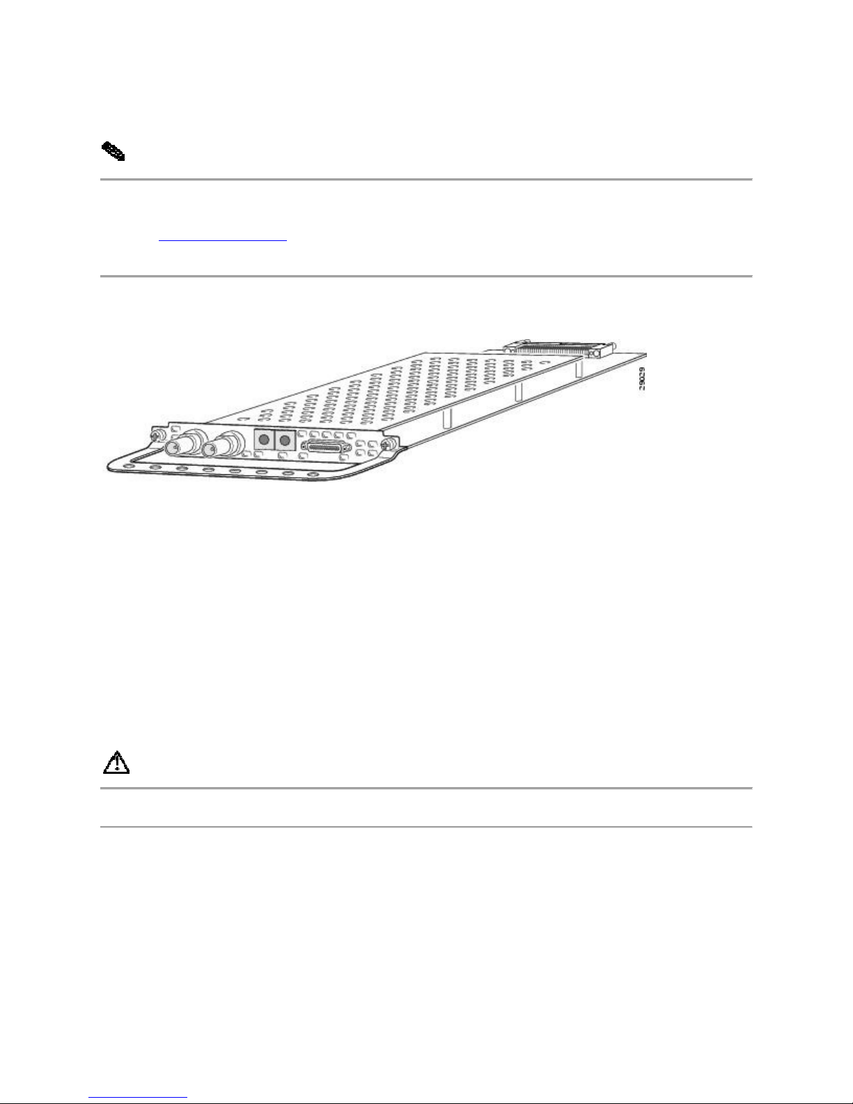
The T3 DFC provides physical line termination for a channelized T3 ingress trunk line. It uses an
onboard multiplexer to multiplex 28 channelized T1 lines into a single channelized T3 line. (See
Figure 4-1.)
The T3 DFC provides physical line termination for up to 672 DS0 channels and uses onboard
HDLC controllers to terminate digital (ISDN) calls.
You can use the bantam jacks on the DFC to monitor a T1 line or test any one of the individual
T1 circuits in drop and insert mode.
Page 2
You can install a T3 DFC in any DFC slot of the universal gateway chassis.
Note The Cisco AS5350 and Cisco AS5400 support only one type of WAN DFC at a time.
Refer to "Troubleshooting," for more information.
Figure 4-1 T3 Dial Feature Card
Online Installation and Removal (OIR) of the T3 DFC
Overview
To remove a DFC without dropping any calls or connections, you will need to take the DFC out
of service by using the busyout command to disable the DFC. The busyout command is
executed on a per DFC basis and will gracefully disable the card by waiting for the active
services to terminate.
If you have active calls on the DFC after executing the busyout command, wait for the calls to
drop. Use the show busyout command to view the status of the termination process.
Caution To avoid erroneous failure messages, remove or insert only one DFC at a time.
When you replace a DFC with a new DFC of the same type in the same slot, the system software
will recognize the new trunk interfaces and bring them up automatically.
If you replace the existing DFC with a new DFC of a different type, you will have to reconfigure
the system. For configuration details, refer to the Cisco AS5350 and Cisco AS5400 Universal
Gateway Software Configuration Guide.
Page 3

Removing the T3 DFC
To remove the T3 DFC, follow these steps:
Note Following these steps are examples of the output from each command.
Step 1 Determine which slot the DFC is in (See Figure 4-2 and Figure 4-3.) by entering the
show chassis command in privileged EXEC mode:
Router# show chassis slot
Figure 4-2 Slot Numbering on the Cisco AS5350 Chassis
Figure 4-3 Slot Numbering on the Cisco AS5400 Chassis
Step 2 Initialize the software busyout procedure by entering the busyout command:
Router# busyout slot-number
Step 3 Enter the show busyout command to check busyout status for that specific slot:
Page 4

Router# show busyout slot-number
Step 4 You may use the clear port command to immediately disable active calls on the universal
port card. Use the show controller command to show the universal port card associated with the
T1 or E1 DFC.
Router# show controller t1/e1 slot-number/control-number timeslot timeslotnumber
Router# clear port slot-number/port number
Note The clear port command only applies to the universal port DFC.
Step 5 Verify that the OIR/MAINT LED is off; this indicates that the DFC is offline and ready
to be removed.
Note The OK/MAINT LED is green before you enter the busyout command. After you enter the
busyout command, the LED changes to yellow. The LED turns off after all calls are
disconnected and resources are taken out of service, indicating that busyout is complete.
Step 6 Attach an ESD-preventive wrist strap.
Warning Do not work on the system or connect or disconnect cables during periods of lightning
activity. To see translations of the warnings that appear in this publication, refer to the
Regulatory Compliance and Safety Information document that accompanied this device.
Step 7 Disconnect all interface cables from the DFC and secure them out of the way.
Page 5

Note OIR of the T3 DFC is similar to that of the T1 or E1 DFC. To see an example of the
output during online insertion and removal of an E1 DFC refer to Chapter 3, "T1 and E1 Dial
Feature Cards"
Step 8 Loosen the two captive screws that secure the DFC to the chassis until each screw is free
of the chassis. (See Figure 4-4 and Figure 4-5.)
Figure 4-4 Loosen the Captive Screws on the Cisco AS5350
Figure 4-5 Loosen the Captive Screws on the Cisco AS5400
Step 9 Grasp the DFC handle with one hand and pull the card toward you until the card slides
free of the chassis. Grasp the ventilated metal cover with your other hand to support and guide
the DFC out of the slot. (See Figure 4-6 and Figure 4-7.)
Caution Avoid touching any pins or circuit board components during removal and installation
of the DFC.
Page 6

Figure 4-6 Remove the DFC from the Cisco AS5350
Figure 4-7 Remove the DFC from the Cisco AS5400
Step 10 After you remove the DFC from the chassis, set it aside on an ESD-preventive mat.
Step 11 If a DFC slot on the carrier card is to remain empty, install a blank cover over the open
DFC slot to ensure proper airflow inside the chassis. (See Figure 4-8.)
Figure 4-8 Blank DFC Cover
Installing the T3 DFC
Warning Do not work on the system or connect or disconnect cables during periods of lightning
activity. To see translations of the warnings that appear in this publication, refer to the
Regulatory Compliance and Safety Information document that accompanied this device.
Page 7

Note When you replace a DFC with a new DFC of the same type in the same slot, the system
software will recognize the new trunk interfaces and bring them up automatically. If you replace
the existing DFC with a new DFC of a different type, you will have to reconfigure the system.
For configuration details, refer to the Cisco AS5350 and Cisco AS5400 Universal Gateway
Software Configuration Guide.
To install the T3 DFC, follow these steps:
Step 1 Attach an ESD-preventive wrist strap.
Step 2 Slide the DFC into the slot until the connector pins make contact with the carrier card
backplane connector. (See Figure 4-9 and Figure 4-10.)
Figure 4-9 Install the T3 DFC in the Cisco AS5350
Figure 4-10 Install the T3 DFC in the Cisco AS5400
Step 3 Align the captive screws with their holes, and seat the card completely.
Step 4 Tighten the screws to secure the DFC to the chassis. (See Figure 4-11 and Figure 4-12.)
Figure 4-11 Tighten the Captive Screws on the Cisco AS5350
Page 8

Figure 4-12 Tighten the Captive Screws on the Cisco AS5400
Step 5 Check the card LEDs to verify that the card is working properly. For information about
dial feature card LEDs, refer to "Troubleshooting"
Getting Help
For information about technical support, onsite service, and exchange and repair services, refer
to the "Obtaining Technical Assistance" section on page -xii in the "Preface."
Where to Go Next
The remaining chapters of this guide include information on installing and troubleshooting DFCs
and creating cables.
• Chapter 5, "Universal Port Dial Feature Card."
• "Troubleshooting."
Page 9

• "Cabling Specifications."
 Loading...