

Page 1
Cisco TelePresence SX80
Contents
Introduction
Connecting to the codec
The physical interface
Socket details
Contact us
Physical interface guide
for Cisco TelePresence SX80
D15121.01 SX80 Physical Interface Guide, JUNE 2014. www.cisco.com — Copyright © 2014 Cisco Systems, Inc. All rights reserved.
1
Page 2

Cisco TelePresence SX80 Physical Interface Guide
Contents
Introduction
Connecting to the codec
The physical interface
Socket details
Contact us
Contents
Thank you for choosing Cisco!
Your Cisco product has been designed to give you many
years of safe, reliable operation.
Our main objective with this guide is to address your goals
and needs. Please let us know how well we succeeded!
May we recommend that you visit the Cisco web site
regularly for updated versions of this guide.
The user documentation can be found on
► http://www.cisco.com/go/telepresence/docs
How to use this guide
The top menu bar and the entries in the Table of contents are
all hyperlinks. You can click on them to go to the topic.
Table of contents
Introduction ............................................................................ 3
User documentation ................................................................ 4
Connecting to the codec .......................................................5
Connect to LAN, microphones, loudspeakers, Touch 10,
displays and power .................................................................. 6
Connect a PC (optional) ........................................................... 7
About cameras......................................................................... 8
Connecting Cisco TelePresence SpeakerTrack 60 .................9
Connecting Cisco TelePresence Precision 60 ...................... 10
Connecting Cisco TelePresence PrecisionHD 1080p 4xS2 ... 11
The physical interface .......................................................... 12
The front panel ....................................................................... 13
The rear panel—overview ....................................................... 14
Socket details ...................................................................... 15
Audio details .......................................................................... 16
GPIO details ........................................................................... 17
Intellectual property rights ..................................................... 18
Cisco contacts ..................................................................... 18
D15121.01 SX80 Physical Interface Guide, JUNE 2014. www.cisco.com — Copyright © 2014 Cisco Systems, Inc. All rights reserved.
2
Page 3

Cisco TelePresence SX80 Physical Interface Guide
Contents
Introduction
Connecting to the codec
The physical interface
Socket details
Contact us
Introduction
Chapter 1
Introduction
D15121.01 SX80 Physical Interface Guide, JUNE 2014. www.cisco.com — Copyright © 2014 Cisco Systems, Inc. All rights reserved.
3
Page 4

Cisco TelePresence SX80 Physical Interface Guide
Contents
Introduction
Connecting to the codec
The physical interface
Socket details
Contact us
Introduction
This document describes the physical inter face of the
following codec:
• Cisco TelePresence SX80
User documentation
The user documentation for the Cisco TelePresence systems
running the TC software includes several guides suitable for
various user groups.
• Installation guide:
How to install the product
• Getting started guide:
Initial configurations required to get the system up and
running
• Administering TC Endpoints on CUCM:
Tasks to perform to start using the product with the Cisco
Unified Communications Manager (CUCM)
• Administrator guide (this guide):
Information required to administer your product
• Quick reference guides:
How to use the product
• User guides:
How to use the product
• API reference guide:
How to use the Application Programmer Interface (API),
and reference guide for the command line commands
• Video conferencing room primer:
General guidelines for room design and best practice
• Video conference room acoustics guidelines:
Things to do to improve the perceived audio quality
• Software release notes
• Regulatory compliance and safety information guide
• Legal & license information
Downloading the user documentation
We recommend you visit the Cisco web site regularly for
updated versions of the user documentation. Go to:
► http://www.cisco.com/go/sx-docs
D15121.01 SX80 Physical Interface Guide, JUNE 2014. www.cisco.com — Copyright © 2014 Cisco Systems, Inc. All rights reserved.
4
Page 5

Cisco TelePresence SX80 Physical Interface Guide
Contents
Introduction
Connecting to the codec
The physical interface
Socket details
Contact us
Connecting to the codec
Chapter 2
Connecting to the codec
D15121.01 SX80 Physical Interface Guide, JUNE 2014. www.cisco.com — Copyright © 2014 Cisco Systems, Inc. All rights reserved.
5
Page 6
Cisco TelePresence SX80 Physical Interface Guide
Contents
Introduction
Connecting to the codec
The physical interface
Socket details
Contact us
Connecting to the codec
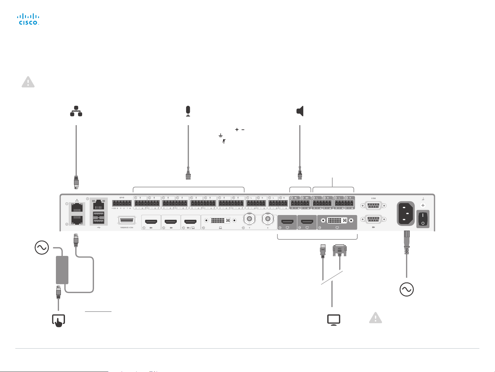
Connect to LAN, microphones, loudspeakers, Touch 10, displays and power
Make sure all units are switched off when connecting or disconnecting cables.
Power
(100-240 VAC,
50/60 Hz)
AP
PoE
injector
SWITCH
LA N (RJ-45)
Always use the
st
1
Ethernet port for
LAN, as outlined.
Touch 10 control panel (RJ-45)
Insert the provided PoE injector between Touch 10
and the codec’s 2
nd
or 3rd Ethernet port2.
Microphones, max 8
(Euroblock, 3.5 mm)
If your microphone cable
has 3 pins, use , and
ground ( ) and leave the
mute pin (
) unused.
Loudspeakers, mono or stereo
(Euroblock, 3.5 mm)
Use speakers with amplifiers. The
speaker/amplifier should have
balanced input to avoid ground loop
noise.
Displays, max 3
(2 HDMI, 1 DVI-I)
Audio Line level outputs
1
Power (100-240 VAC, 50/60 Hz)
1
The audio line outputs may be configured to be used for loudspeakers.
2
The Ethernet connector is behind the lid at the rear of Touch 10. The Ethernet cable between Touch 10
and the PoE injector must be PoE rated (provided). The Ethernet cable between the PoE injector and the
codec is not required to be PoE rated (not provided).
D15121.01 SX80 Physical Interface Guide, JUNE 2014. www.cisco.com — Copyright © 2014 Cisco Systems, Inc. All rights reserved.
6
Always use the provided power cable.
The codec inlet or the wall socket
outlet must be easily accessible after
installation.
Page 7

Cisco TelePresence SX80 Physical Interface Guide
Contents
Introduction
Connecting to the codec
The physical interface
Socket details
Contact us
Connecting to the codec
Connect a PC (optional)
A PC can be connected to the codec to enable sharing of
content locally or with conference participants.
Cisco offers a PC presentation cable that connects the
codec's DVI-I input and Audio line in port (Euroblock), to
the PC's VGA and mini jack connectors.
Alternatively, you can use a standard HDMI cable (not
included).
PC, max 2
(DVI-I/Euroblock or HDMI)
D15121.01 SX80 Physical Interface Guide, JUNE 2014. www.cisco.com — Copyright © 2014 Cisco Systems, Inc. All rights reserved.
7
Page 8

Cisco TelePresence SX80 Physical Interface Guide
Contents
Introduction
Connecting to the codec
The physical interface
Socket details
Contact us
Connecting to the codec
About cameras
The codec has three HDMI camera inputs, and can therefore support up to three cameras.
Cisco provides the following cameras:
Cisco TelePresence SpeakerTrack 60 is based on
two Cisco TelePresence Precision 60 cameras and
a microphone panel for advanced speaker tracking.
Cisco TelePresence Precision 60 is a full HD
camera with 1080p60 resolution, 20x total zoom,
and wide angle view.
Cisco TelePresence PrecisionHD 1080p 4xS2 is
a full HD camera with 1080p60 resolution and 4x
optical zoom.
You can use any combination of these cameras, as long as the maximum number of cameras does not
exceed three
See how to connect the cameras on the following pages.
For more details about the Cisco cameras, refer to camera guides that are available at
► http://www.cisco.com/go/camera-docs
4
Note that Cisco TelePresence SpeakerTrack 60 consists of two cameras.
D15121.01 SX80 Physical Interface Guide, JUNE 2014. www.cisco.com — Copyright © 2014 Cisco Systems, Inc. All rights reserved.
4
.
8
Page 9

Cisco TelePresence SX80 Physical Interface Guide
Contents
Introduction
Connecting to the codec
The physical interface
Socket details
Contact us
Connecting to the codec
Connecting Cisco TelePresence SpeakerTrack 60
Connect the two cameras in the SpeakerTrack 60 assembly
to the codec’s 1st and 2
Also connect SpeakerTrack 60 to the codec’s 2
Ethernet port, and to power.
nd
camera inputs (HDMI).
1
nd
or 3rd
Refer to the installation guide that comes with SpeakerTrack
60 for further information about camera assembly and
cabling.
Tip! Should you for any reason run out of Ethernet ports, just
connect a switch to the codec’s 2
Never connect the switch to the 1
nd
or 3rd Ethernet port.
st
Ethernet port. This is
reserved for LAN connection only.
Power
adapter
Power
(100-240 VAC, 50/60 Hz)
1
Note that the camera surface is hot when the camera is in operation.
D15121.01 SX80 Physical Interface Guide, JUNE 2014. www.cisco.com — Copyright © 2014 Cisco Systems, Inc. All rights reserved.
9
Always use the provided power cable and
adapter (12 V
, minimum 6.5 A).
DC
Page 10

Cisco TelePresence SX80 Physical Interface Guide
Contents
Introduction
Connecting to the codec
The physical interface
Socket details
Contact us
Connecting to the codec
Connecting Cisco TelePresence Precision 60
Connect the camera to one of the codec’s camera inputs
(HDMI).
st
Cisco recommends using the 1
camera.
Also connect the camera to the codec’s 2
port, and to power.
1
Tip! Should you for any reason run out of Ethernet ports, just
connect a switch to the codec’s 2
Never connect the switch to the 1
reserved for LAN connection only.
camera input for the main
nd
or 3rd Ethernet
nd
or 3rd Ethernet port.
st
Ethernet port. This is
Power
adapter
Power
(100-240 VAC, 50/60 Hz)
1
Note that the camera surface is hot when the camera is in operation.
D15121.01 SX80 Physical Interface Guide, JUNE 2014. www.cisco.com — Copyright © 2014 Cisco Systems, Inc. All rights reserved.
10
Always use the provided power cable and
adapter (12 V
, minimum 3 A).
DC
Page 11

Cisco TelePresence SX80 Physical Interface Guide
Contents
Introduction
Connecting to the codec
The physical interface
Socket details
Contact us
Connecting to the codec
Connecting Cisco TelePresence PrecisionHD 1080p 4xS2
Connect the camera to one of the codec’s camera inputs
(HDMI).
st
Cisco recommends using the 1
camera.
Also connect the camera to the codec’s dedicated camera
control port (D-SUB 9), and to power.
camera input for the main
Power
adapter
Power
(100-240 VAC, 50/60 Hz)
D15121.01 SX80 Physical Interface Guide, JUNE 2014. www.cisco.com — Copyright © 2014 Cisco Systems, Inc. All rights reserved.
11
Always use the provided power cable and
adapter (12 V
, minimum 2 A).
DC
Page 12

Cisco TelePresence SX80 Physical Interface Guide
Contents
Introduction
Connecting to the codec
The physical interface
Socket details
Contact us
The physical interface
Chapter 3
The physical interface
D15121.01 SX80 Physical Interface Guide, JUNE 2014. www.cisco.com — Copyright © 2014 Cisco Systems, Inc. All rights reserved.
12
Page 13
Cisco TelePresence SX80 Physical Interface Guide
Contents
Introduction
Connecting to the codec
The physical interface
Socket details
Contact us
The physical interface
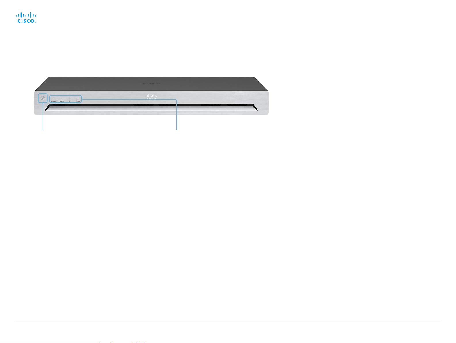
The front panel
Shutdown button
The shutdown button on the front panel can be
used to switch the codec on/off, provided the
power switch on the codec’s rear side is on.
• To switch off the codec, hold the button
until the LEDs go out.
• To switch on the codec, hold the button
until the LEDs flash. It may take a few
minutes for the codec to start up. The
system is ready for use when the Power
LED lights steadily.
The shutdown button can also be used to
factory reset the codec, more about this can
be found in the Administrator guide for SX80.
Front panel LEDs
Power:
Blinks when the system is starting up.
Steady light when the codec is ready for use.
Pulsates when the codec is in standby.
In Call:
Steady light when in call.
IR:
Not in use.
Alarm:
Lights steady when a serious error occurs.
D15121.01 SX80 Physical Interface Guide, JUNE 2014. www.cisco.com — Copyright © 2014 Cisco Systems, Inc. All rights reserved.
13
Page 14
Cisco TelePresence SX80 Physical Interface Guide
Contents
Introduction
Connecting to the codec
The physical interface
Socket details
Contact us
The physical interface
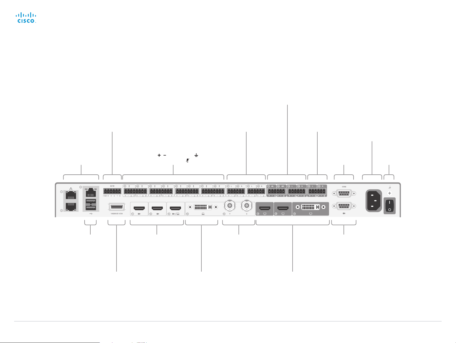
The rear panel—overview
4 × program mable
GPIO pins
(Euroblock, 3.5 mm)
2 × loudspeakers, mono or stereo
This output requires a power amplifier or
active speakers. The speaker/amplifier
should have balanced input to avoid
2 × stereo audio
line in,
e.g. from PC
(Euroblock, 3.5 mm)
(Euroblock, 3.5 mm)
ground loop noise.
2 × stereo audio line out,
(Euroblock, 3.5 mm)
3 × LAN (RJ-45)
Always use the
st
Ethernet port
1
Tip! Should you for any
reason run out of Ethernet
ports, just connect a
switch to the codec’s 2
nd
3rd Ethernet port.
Never connect the switch
st
to the 1
Ethernet port.
This is reserved for L AN
connection only.
for LAN.
or
2 × USB
8 × micropho nes (Euroblo ck, 3.5 mm)
If your microphone cable has 3 pins,
use , and ground ( ),
leaving the mute pin ( ) unused.
3 × camera s (HDMI)
Analog video input:
Composite: Y
S-video: Y and C
(BNC, BNC)
10 Gb Ethernet Video input,
e.g. from PC
(DVI-I)
Note: These video inputs are mutually
excluding, you may only use either the
DVI-I, the Composite, or the S-video
at a time.
3 × displays
(2 HDMI, 1 DVI-I)
Serial port
(D-SUB 9)
Camera control
for the PrecisionHD
1080p 4xS2
camera
3
(D-SUB 9)
Power
Ground
(For chassis grounding)
D15121.01 SX80 Physical Interface Guide, JUNE 2014. www.cisco.com — Copyright © 2014 Cisco Systems, Inc. All rights reserved.
14
Page 15

Cisco TelePresence SX80 Physical Interface Guide
Contents
Introduction
Connecting to the codec
The physical interface
Socket details
Contact us
Socket details
Chapter 4
Socket details
D15121.01 SX80 Physical Interface Guide, JUNE 2014. www.cisco.com — Copyright © 2014 Cisco Systems, Inc. All rights reserved.
15
Page 16

Cisco TelePresence SX80 Physical Interface Guide
MALE
(ANY UNBALANCED CONNECTOR)
(CHECK: NO STANDARD POLARITY ON EUROBLOCKS)
MALE
MALE
1
3
2
1
2
3
1
2
3
To Input
S=SHIELD
R=BLACK
T=RED
S=SHIELD
R=BLACK
T=RED
S=SHIELD
R=BLACK
T=RED
S=SHIELD
R=BLACK
T=RED
S=SHIELD
R=BLACK
T=RED
S=BLACK
T=RED
S=BLACK
T=RED
S=BLACK
T=RED
S=BLACK
T=RED
S=SHIELD
T=RED
S=SHIELD
T=RED
S=SHIELD
T=RED
S=SHIELD
T=RED
S=SHIELD
T=RED
S=SHIELD
T=RED
S=SHIELD
T=RED
S=SHIELD
T=RED
3=BLACK
2=RED
1=SHIELD
3=BLACK
2=RED
1=SHIELD
3=BLACK
2=RED
1=SHIELD
SHIELD
BLACK
SHIELD
RED
BLACK
SHIELD
RED
BLACK
RED
SHIELD
SHIELD
BLACK
RED
SHIELD
BLACK
RED
SHIELD
BLACK
RED
SHIELD
BLACK
RED
SHIELD
BLACK
RED
SHIELD
RED
SHIELD
RED
SHIELD
RED
SHIELD
RED
BLACK
RED
N/C
N/C
BLACK
RED
BLACK
RED
BLACK
RED
RED
SHIELD
RED
SHIELD
RED
SHIELD
RED
2-CONDUCTOR SHIELDED CABLE
2-CONDUCTOR SHIELDED CABLE
2-CONDUCTOR SHIELDED CABLE
2-CONDUCTOR SHIELDED CABLE
2-CONDUCTOR SHIELDED CABLE
2-CONDUCTOR SHIELDED CABLE
1-CONDUCTOR SHIELDED CABLE
1-CONDUCTOR SHIELDED CABLE
1-CONDUCTOR SHIELDED CABLE
1-CONDUCTOR SHIELDED CABLE
Contents
Introduction
Connecting to the codec
The physical interface
Socket details
Contact us
Socket details
Audio details
Audio Input / Output Levels
Microphone In Line In Line Out
Min. level –48 dBu –2 dBu –2 dBu
Default level –36 dBu 6 dBu 12 dBu
Max. level 22 dBu 22 dBu 22 dBu
No. of steps 70 24 24
rms)
0 dBu ≡ 1mW @ 600 Ω (0.775 V
T=RED
S=BLACK
(CHECK: NO STANDARD POLARITY ON EUROBLOCKS)
–
Output side
+
RED
BLACK
RED
BLACK
SHIELD
CROSS-COUPLED OUTPUT ONLY: CONNECT BLACK TO SHIELD AT THIS END
2-CONDUCTOR SHIELDED CABLE
2-CONDUCTOR SHIELDED CABLE
RED
BLACK
SHIELD
(ANY UNBALANCED CONNECTOR)
RED
BLACK
+
–
T=RED
S=BLACK
These illustrations
show best practice
when connecting the
SX80 to unbalanced
connectors.
Input side
Note: The Microphone inputs are congured for
the use of Euroblocks with up to 4 ports, while
the Line In / Line Out are congured for the use of
Euroblocks with 3 ports only.
If you use Euroblocks with 3 ports as microphone
connectors make sure the Euroblock is inserted
so that the Microphone Mute is not engaged, i.e.
insert it in the leftmost position possible, marked
Connect as indicated by green when
using Euroblocks with 3 connectors
for microphones. Do not connect as
indicated by red.
using green in the lower left Fig.
D15121.01 SX80 Physical Interface Guide, JUNE 2014. www.cisco.com — Copyright © 2014 Cisco Systems, Inc. All rights reserved.
16
Page 17

Cisco TelePresence SX80 Physical Interface Guide
Contents
Introduction
Connecting to the codec
The physical interface
Socket details
Contact us
Socket details
GPIO details
1× GPIO (General Purpose Input/Output)
6 pins Euroblock, with 4 ports for On/O control, GND and +12V.
You can congure input/output integrations by using pre–dened
behavior. Exposure of states and commands for external control
requires external programming.
For information about the API commands, see the API Guide for
the codec, go to:
http://www.cisco.com/go/telepresence/docs
Operating principles
• A contact closure between the GND and a GPIO port pin is
detected as a low input signal.
• When used for voltage inputs, the GPIO port detects it as:
• Low signal for voltages 0–1 V
• High signal for voltages 2–12 V
• When used for outputs, the GPIO port acts as a switch
to GND, and is rated for 500mA @ 48V DC. The +12V pin
provides +12 VDC, and is capable of sourcing up to 500mA.
• The GND connector is a common ground for all pins in the
GPIO port.
DC
DC
D15121.01 SX80 Physical Interface Guide, JUNE 2014. www.cisco.com — Copyright © 2014 Cisco Systems, Inc. All rights reserved.
17
Page 18

Cisco TelePresence SX80 Physical Interface Guide
Contents
Introduction
Connecting to the codec
The physical interface
Socket details
Contact usContact us
Intellectual property rights
THE SPECIFICATIONS AND INFORMATION REGARDING THE
PRODUCTS IN THIS M ANUAL ARE SUBJECT TO CHANGE
WITHOUT NOTICE. ALL STATEMENTS, INFORMATION, AND
RECOMMENDATIONS IN THIS MANUAL ARE BELIEVED TO BE
ACCUR ATE BUT ARE PRESENTED WITHOUT WARR ANT Y OF
ANY KIND, EXPRESS OR IMPLIED. USERS MUST TAKE FULL
RESPONSIBILITY FOR THEIR APPLICATION OF ANY PRODUCTS.
THE SOF TWARE LICENSE AND LIMITED WARRANTY FOR THE
ACCOMPANYING PRODUCT ARE SET FORTH IN THE INFORM ATION
PACKET THAT SHIPPED WITH THE PRODUCT AND ARE
INCORPORATED HEREIN BY THIS REFERENCE. IF YOU ARE UNABLE
TO LOCATE THE SOFTWARE LICENSE OR LIMITED WARRANTY,
CONTACT YOUR CISCO REPRESENTATIVE FOR A COPY.
The Cisco implementation of TCP header compression is an
adaptation of a program developed by the University of California,
Berkeley (UCB) as part of UCB’s public domain version of the UNIX
operating system. All rights reser ved. Copyright © 1981, Regents of
the University of California.
NOTWITHSTANDING ANY OTHER WARRANT Y HEREIN, ALL
DOCUMENT FILES AND SOFTWARE OF THESE SUPPLIERS ARE
PROVIDED “AS IS” WITH ALL FAULTS. CISCO AND THE ABOVENAMED SUPPLIERS DISCLAIM ALL WARRANTIES, E XPRESSED
OR IMPLIED, INCLUDING, WITHOUT LIMITATION, THOSE OF
MERCHANTABILITY, FITNESS FOR A PARTICULAR PURPOSE AND
NONINFRINGEMENT OR ARISING FROM A COURSE OF DEALING,
USAGE, OR TRADE PRACTICE.
IN NO EVENT SHALL CISCO OR ITS SUPPLIERS BE LIABLE FOR ANY
INDIRECT, SPECIAL, CONSEQUENTIAL, OR INCIDENTAL DAMAGES,
INCLUDING, WITHOUT LIMITATION, LOST PROFITS OR LOSS OR
DAMAGE TO DATA ARISING OUT OF THE USE OR INABILITY TO
USE THIS MANUAL, EVEN IF CISCO OR ITS SUPPLIERS HAVE BEEN
ADVISED OF THE POSSIBILITY OF SUCH DAMAGES.
Cisco and the Cisco Logo are trademarks of Cisco Systems, Inc. and/
or its affiliates in the U.S. and other countries. A listing of Cisco’s
trademarks can be found at w ww.cisco.com/go/trademarks. Third
party trademarks mentioned are the property of their respective
owners. The use of the word par tner does not imply a partnership
relationship bet ween Cisco and any other company. (1005R)
Any Internet Protocol (IP) addresses and phone numbers used in
this document are not intended to be actual addresses and phone
numbers. Any examples, command display output, network topology
diagrams, and other figures included in the document are shown for
illustrative purposes only. Any use of actual IP addresses or phone
numbers in illustrative content is unintentional and coincidental.
TANDBERG is now a part of Cisco. TANDBERG® is a registered
trademark belonging to Tandberg ASA.
Cisco contacts
On our web site you will find an overview of the worldwide Cisco contacts.
Go to: ► http://www.cisco.com/go/offices
Corporate Headquarters
Cisco Systems, Inc.
170 West Tasman Dr.
San Jose, CA 95134 USA
D15121.01 SX80 Physical Interface Guide, JUNE 2014. www.cisco.com — Copyright © 2014 Cisco Systems, Inc. All rights reserved.
18
 Loading...