

Page 1
Cisco TelePresence SX10 Quick Set Administrator Guide
Introduction
Configuration
Peripherals
Maintenance
System settings
Appendices
Collaboration Endpoint software version 9.0
APRI L 2017
Administrator guide
for Cisco TelePresence SX10 Quick Set
D153 30. 05 SX10 Administrator Guide CE9.0, APRIL 2017. www.cisco.com — Copyright © 2017 Cisco Systems, Inc. A ll rights reserved.
1
Page 2

Cisco TelePresence SX10 Quick Set Administrator Guide
Introduction
Configuration
Peripherals
Maintenance
System settings
Appendices
Thank you for choosing Cisco!
Your Cisco product has been designed to give you many
years of safe, reliable operation.
This part of the product documentation is aimed at
administrators working with the setup and configuration of
the video system.
Our main objective with this Administrator guide is to
address your goals and needs. Please let us know how
well we succeeded!
May we recommend that you visit the Cisco web site
regularly for updated versions of this guide.
The user documentation can be found on
► http://www.cisco.com/go/sx-docs
How to use this guide
The top menu bar and the entries in the Table of contents
are all hyperlinks. You can click on them to go to the topic.
Table of contents
Introduction ....................................................................................................................... 4
User documentation and software ....................................................................................... 5
What’s new in CE9 ................................................................................................................ 6
SX10 Quick Set at a glance ................................................................................................... 9
Power On and Off ............................................................................................................... 10
LED indicators ......................................................................................................................11
How to administer the video system ....................................................................................12
Configuration .................................................................................................................. 16
User administration ..............................................................................................................17
Change the system passphrase ......................................................................................... 18
Set a PIN code for the Settings menu ................................................................................ 19
System configuration .......................................................................................................... 20
Add a sign in banner ........................................................................................................... 21
Manage the service certificates of the video system ......................................................... 22
Manage the list of trusted certificate authorities (CAs) ...................................................... 23
Set up secure audit logging ................................................................................................ 24
Manage pre-installed certificates for CUCM via Expressway provisioning ........................ 25
Delete CUCM trust lists....................................................................................................... 26
Change the persistency mode............................................................................................ 27
Set strong security mode ................................................................................................... 28
Set up Intelligent Proximity for content sharing .................................................................. 29
Adjust the video quality to call rate ratio ............................................................................. 34
Packet loss resilience - ClearPath ...................................................................................... 35
Choose wallpaper ............................................................................................................... 36
Choose a ringtone and set the ringtone volume ................................................................ 37
Manage local contacts ........................................................................................................ 38
Peripherals ...................................................................................................................... 39
Extend the number of input sources ................................................................................... 40
Real-time communication requirements for displays ..........................................................41
Connect the Touch 10 controller ........................................................................................ 42
Maintenance ................................................................................................................... 44
Upgrade the system software ............................................................................................ 45
Add option keys .................................................................................................................. 47
System status ..................................................................................................................... 48
Run diagnostics ................................................................................................................... 49
Download log files ............................................................................................................... 50
Create a remote support user .............................................................................................51
D153 30. 05 SX10 Administrator Guide CE9.0, APRIL 2017. www.cisco.com — Copyright © 2017 Cisco Systems, Inc. A ll rights reserved.
2
Page 3

Cisco TelePresence SX10 Quick Set Administrator Guide
Introduction
Configuration
Peripherals
Maintenance
System settings
Appendices
Backup or restore a configuration....................................................................................... 52
Revert to the previously used software image ................................................................... 53
Factory reset the video system .......................................................................................... 54
Factory reset the Touch 10 ................................................................................................. 57
Capture user interface screenshots ................................................................................... 58
System settings .............................................................................................................. 59
Overview of the system settings ........................................................................................ 60
Audio settings ..................................................................................................................... 64
CallHistory settings ............................................................................................................. 66
Cameras settings ................................................................................................................ 67
Conference settings ........................................................................................................... 69
FacilityService settings ....................................................................................................... 73
H323 settings .......................................................................................................................74
Logging settings ................................................................................................................. 77
Network settings ................................................................................................................. 78
NetworkServices settings ................................................................................................... 85
Peripherals settings ............................................................................................................ 90
Phonebook settings ............................................................................................................ 92
Provisioning settings ........................................................................................................... 93
Proximity settings................................................................................................................ 96
RTP settings ........................................................................................................................ 97
Security settings ................................................................................................................. 98
SerialPort settings ............................................................................................................. 100
SIP settings ........................................................................................................................101
Standby settings ............................................................................................................... 105
SystemUnit settings .......................................................................................................... 106
Time settings .................................................................................................................... 107
UserInterface settings ........................................................................................................110
UserManagement settings ................................................................................................. 112
Video settings .................................................................................................................... 114
Experimental settings ........................................................................................................121
Appendices ................................................................................................................... 122
How to use the remote control and the on-screen user interface ................................... 123
How to use Touch 10 .........................................................................................................124
Set up remote monitoring ................................................................................................. 125
Access call information while using the web interface ..................................................... 126
Place a call using the web interface ..................................................................................127
Share content using the web interface ............................................................................. 129
Local layout control ........................................................................................................... 130
Control a local camera .......................................................................................................131
Control a far end camera .................................................................................................. 132
Add in-room controls to Touch 10 ................................................................................... 133
Manage startup scripts ..................................................................................................... 13 4
Access the video system’s XML files .............................................................................. 135
Execute API commands and configurations from the web interface ............................... 136
Serial interface .................................................................................................................. 137
Technical specification ...................................................................................................... 13 8
Supported RFCs ............................................................................................................... 140
User documentation on the Cisco web site .......................................................................141
Cisco contacts ...................................................................................................................142
D153 30. 05 SX10 Administrator Guide CE9.0, APRIL 2017. www.cisco.com — Copyright © 2017 Cisco Systems, Inc. A ll rights reserved.
3
Page 4

Cisco TelePresence SX10 Quick Set Administrator Guide
Introduction
Configuration
Peripherals
Maintenance
System settings
Appendices
Introduction
Chapter 1
Introduction
D153 30. 05 SX10 Administrator Guide CE9.0, APRIL 2017. www.cisco.com — Copyright © 2017 Cisco Systems, Inc. A ll rights reserved.
4
Page 5

Cisco TelePresence SX10 Quick Set Administrator Guide
Introduction
Configuration
Peripherals
Maintenance
System settings
Appendices
Introduction
User documentation and software
Products covered in this guide
• Cisco TelePresence SX10 Quick Set
User documentation
This guide provides you with the information required to
administrate the video system.
The guide primarilly addresses capabilities and
configurations of on-premise registered video systems
(CUCM, VCS), but a sub-set of the capabilities and
configurations also applies to devices that are registered
to our cloud service (Cisco Spark).
Refer to the ► User documentation on the Cisco web site
appendix for more information about the guides for this
product.
Documentation on the Cisco web site
Visit the Cisco web site regularly for updated versions of
the guides:
► http://www.cisco.com/go/sx-docs
Documentation for cloud registered devices
For more information on Cisco Spark room devices, visit:
► https://help.webex.com/community/cisco-cloud-
collab-mgmt
Cisco Project Workplace
Explore the Cisco Project Workplace to find inspiration
and guidelines when preparing an office or meeting room
for video conferencing:
► http://www.cisco.com/go/projectworkplace
Software
Download software for the endpoint from the Cisco web
site:
► http://www.cisco.com/cisco/software/navigator.
html
We recommend reading the Software release notes
(CE9):
► http://www.cisco.com/c/en/us/support/
collaboration-endpoints/telepresence-quick-setseries/tsd-products-support-series-home.html
Converting to CE software
Before upgrading from TC software to CE software,
it is impor tant to consider the upgrade requirements;
otherwise upgrading to CE software can leave you
with a non-functional deployment that requires you to
downgrade.
Refer to the software release notes, and the
► Upgrade the system software cha pte r.
D153 30. 05 SX10 Administrator Guide CE9.0, APRIL 2017. www.cisco.com — Copyright © 2017 Cisco Systems, Inc. A ll rights reserved.
5
Page 6

Cisco TelePresence SX10 Quick Set Administrator Guide
Introduction
Configuration
Peripherals
Maintenance
System settings
Appendices
Introduction
What’s new in CE9
This chapter provides an overview of the new and changed
system settings, and the new features and improvements in
the Cisco Collaboration Endpoint software version 9 (CE9)
compared to CE8.
For more details, we recommend reading the Software
release notes:
► http://www.cisco.com/c/en/us/support/collaboration-
endpoints/telepresence-quick-set-series/tsd-productssupport-series-home.html
New features and improvements in CE9.0
Updated user interface
The user interfaces on the Touch 10, on screen, and
on integrated touch screens have been updated. The
main menu items on the home screen have been
replaced with more prominent activities.
Some of the settings have been removed from the
Touch 10 advanced settings menu to align with the
on-screen display menu.
Wakeup on motion detection
Wakeup on motion detection senses when a person
walks into the conference room and the video system
wakes up automatically. You need to enable the
following setting for this feature to work:
xConfiguration Standby WakeupOnMotionDetection
You can’t manually set the video system in standby
when this feature is enabled.
Updated In-Room Control editor
The In-Room Control editor is updated with a new
look, improved logic and usability for producing a
control interface more efficiently. In addition, a new
directional pad widget and an In-Room Control
simulator is added.
Added language support
We have added support for Potuguese (Portugal) to
the on-screen display and Touch controller menus.
Other changes
• Support for HTTPS client certificates has been
added.
• Unplugging the presentation cable stops the
presentation sharing instantly.
D153 30. 05 SX10 Administrator Guide CE9.0, APRIL 2017. www.cisco.com — Copyright © 2017 Cisco Systems, Inc. A ll rights reserved.
6
Page 7

Cisco TelePresence SX10 Quick Set Administrator Guide
Introduction
Configuration
Peripherals
Maintenance
System settings
Appendices
Introduction
System configuration changes in CE9.0
New configurations
NetworkServices HTTPS Server MinimumTLSVersion
NetworkServices HTTPS StrictTransportSecurity
Peripherals Pairing CiscoTouchPanels EmcResilience
Standby WakeupOnMotionDetection
Configurations that are removed
UserInterface UserPreferences
Conference VideoBandwidth PresentationChannel Weight
Standby AudioMotionDetection
Configurations that are modified
Cameras Camera [n] *
OLD: User role: ADMIN, USER
NEW: User role: ADMIN, INTEGRATOR
UserInterface Language
NEW: Portuguese added to value space
Configurations with the new INTEGRATOR user role
A new user role - INTEGRATOR - is introduced in CE9.0. It has been added to the following
configurations:
Audio DefaultVolume
Audio Input Microphone [n] *
Audio Microphones Mute Enabled
Audio Output Line [n] *
Audio SoundsAndAlerts *
CallHistory Mode
Cameras Camera [n] *
Conference DefaultCall Rate
Conference DoNotDisturb DefaultTimeout
FacilityService *
Peripherals Pairing Ultrasound Volume MaxLevel
Peripherals Pairing Ultrasound Volume Mode
Peripherals Profile *
SerialPort Mode
Standby *
SystemUnit Name
Time Zone
UserInterface OSD Output
UserInterface Wallpaper
Video ActiveSpeaker DefaultPIPPosition
Video Input Connector [n] *
Video Monitors
D153 30. 05 SX10 Administrator Guide CE9.0, APRIL 2017. www.cisco.com — Copyright © 2017 Cisco Systems, Inc. A ll rights reserved.
7
Page 8

Cisco TelePresence SX10 Quick Set Administrator Guide
Introduction
Configuration
Peripherals
Maintenance
System settings
Appendices
Introduction
Video Output Connector [n] CEC Mode
Video Output Connector [n] Resolution
Video Output Connector [n] RGBQuantizationRange
Video Presentation DefaultPIPPosition
Video Selfview Default *
Video Selfview OnCall *
<path> * means that the change applies to all configurations starting with <pat h>.
D153 30. 05 SX10 Administrator Guide CE9.0, APRIL 2017. www.cisco.com — Copyright © 2017 Cisco Systems, Inc. A ll rights reserved.
8
Page 9

Cisco TelePresence SX10 Quick Set Administrator Guide
Introduction
Configuration
Peripherals
Maintenance
System settings
Appendices
Introduction
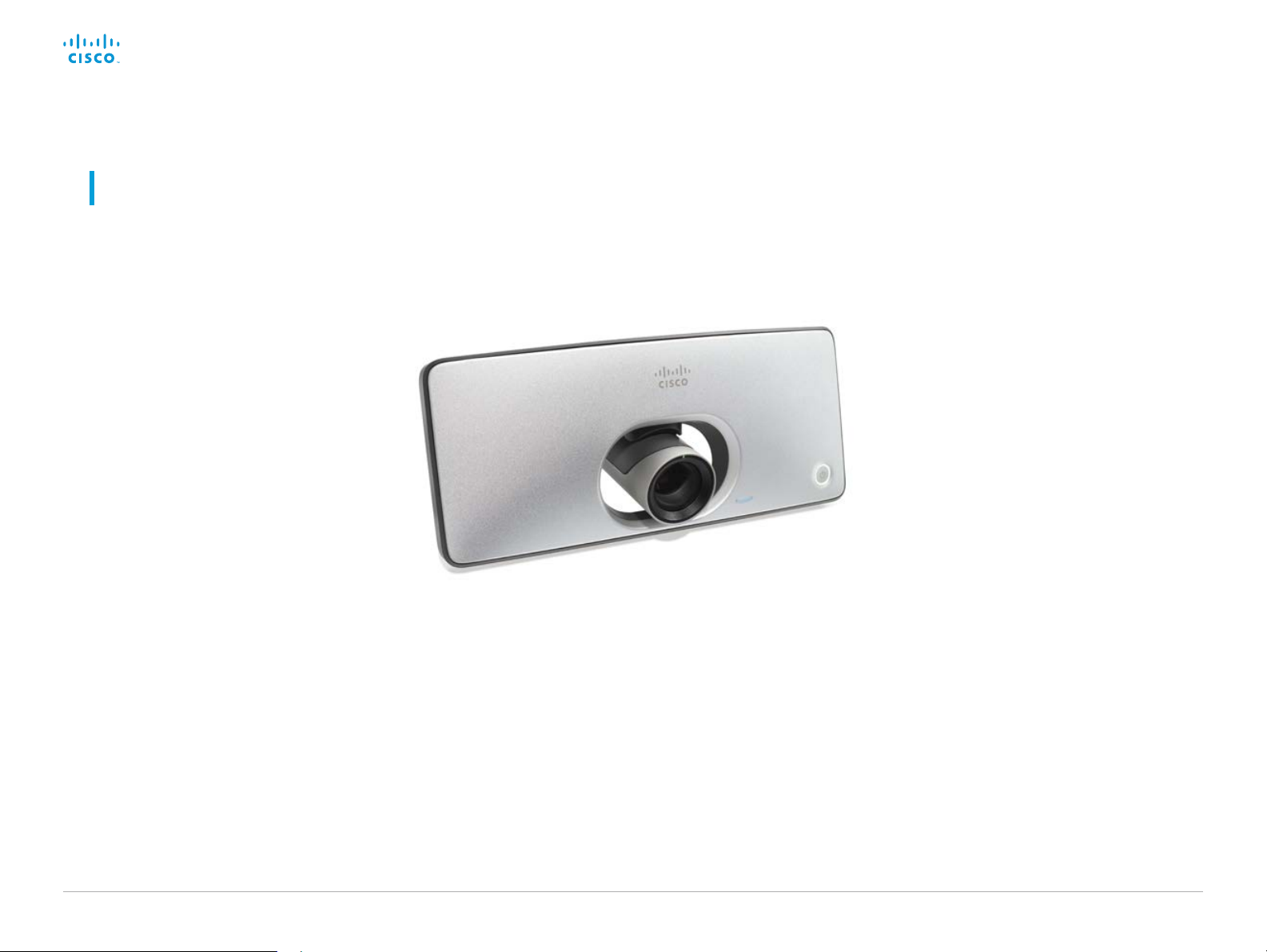
SX10 Quick Set at a glance
The Cisco TelePresence SX10 Quick Set is an all-in-one unit
designed to video-enable small collaboration spaces.
It is a high quality unit that combines camera and codec into
a compact device that is mounted over a standard flat-panel
display. It can be connected to power and LAN through a single
cable for both power and Ethernet (PoE).
The camera has a wide-angle field of view, and provides good
overview even in small spaces. High-definition video is enabled
with 1080p30 resolution.
Features and benefits
• Optimal definition up to 1080p30 with content sharing at
WXGAp5.
• Wide angle 83° horizontal field of view with 5x zoom (optical
and digital).
• Ready-to-use unit with Power over Ethernet (PoE).
• Integrated microphone, and optional external
Cisco TelePresence Table Microphone 20.
• Operation using TRC6 remote control (default), or 10 inch
Touch controller (optional).
• Energy efficient with low power consumption (EU Class B).
• Registers with Cisco Unified Communications Manager
(UCM), Cisco TelePresence Video Communication Server
(VCS), and Cisco Spark.
SX10 Quick Set is delivered with a
TRC6 remote control. You may order the
Cisco TelePresence Touch 10 controller
as an option
SX10 Quick Set mounted on top
of a standard flat-panel display
D153 30. 05 SX10 Administrator Guide CE9.0, APRIL 2017. www.cisco.com — Copyright © 2017 Cisco Systems, Inc. A ll rights reserved.
9
Page 10
Cisco TelePresence SX10 Quick Set Administrator Guide
Introduction
Configuration
Peripherals
Maintenance
System settings
Appendices
Introduction
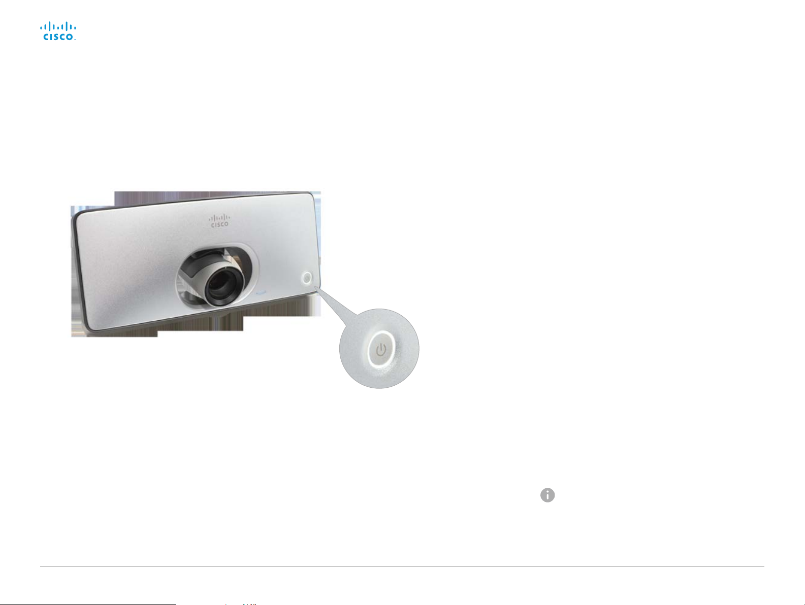
Power On and Off
Power On/Off with the Power button
The power button, with LED indicator, is placed on the front as shown in the illustration.
Power button with LEDs
encircling the button
Restart and standby using the user
interface
Restart the system
1. Select the settings icon (cogwheel) in the status bar of
the user interface.
2. Select System Information > Restart.
3. Select Restart again to confirm your choice.
Enter/exit standby mode
1. Select the settings icon (cogwheel) in the status bar of
the user interface.
2. Select Standby.
Power Off or restart the system remotely
Sign in to the web interface and navigate to Maintenance >
Restart.
Restart the system
Click Restart device... and confirm your choice.
It takes a few minutes before the system is ready for use.
Switch on
If the video system does not
start automatically, press the
power button gently.
The LED is lit while the video
system starts up.
D153 30. 05 SX10 Administrator Guide CE9.0, APRIL 2017. www.cisco.com — Copyright © 2017 Cisco Systems, Inc. A ll rights reserved.
Switch off
Press the power button gently
and hold until the light goes out.
Enter/exit standby mode
Press the power button briefly.
It takes a few seconds before
the unit enters standby.
10
Power Off the system
Click Shutdown device... and confirm your choice.
You cannot power the system on again remotely.
Page 11
Cisco TelePresence SX10 Quick Set Administrator Guide
Introduction
Configuration
Peripherals
Maintenance
System settings
Appendices
Introduction
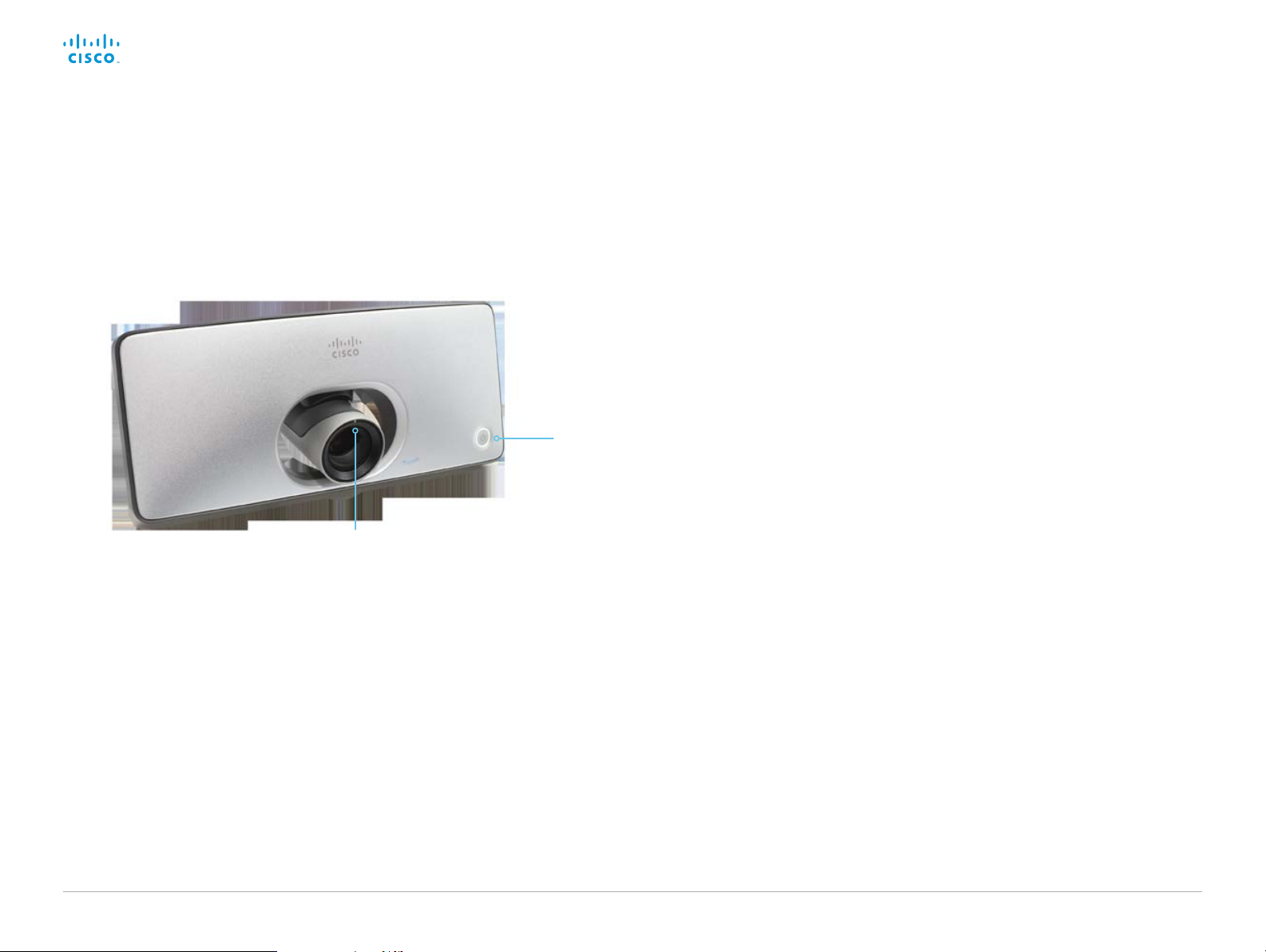
LED indicators
Camera LED
Status LED around
the power button
Status LED
The status LED is a circle around the power button.
The normal LED color is white. A red light indicates
hardware failure.
Normal operation (not standby):
Steady light.
In standby mode:
The LED pulsates slowly.
No network connection:
The LED repeatedly flashes twice.
During startup (boot):
The LED flashes.
Camera LED
The camera LED is just above the camera lens.
Incoming call:
The LED flashes.
In call:
Steady light.
D153 30. 05 SX10 Administrator Guide CE9.0, APRIL 2017. www.cisco.com — Copyright © 2017 Cisco Systems, Inc. A ll rights reserved.
11
Page 12

Cisco TelePresence SX10 Quick Set Administrator Guide
Introduction
Configuration
Peripherals
Maintenance
System settings
Appendices
Introduction
How to administer the video system
In general, we recommend you to use the web interface
to administer and maintain the video system, as
described in this administrator guide.
Alternatively, you can access the API of the video
system by other methods:
• HTTP or HTTPS (also used by the web interface)
• SSH
• Tel n et
• Serial interface (RS-232)
If you want more information about the different access
methods, and how to use the API, refer to the API guide
for the video system.
Tip
If the configuration or status is available in the API, the
web interface setting or status translates into an API
configuration or status as follows:
Set X > Y > Z to Value (we b)
is the same as
xConfiguration X Y Z: Value
Check X > Y > Z status (web)
is the same as
xStatus X Y Z
(API)
(API)
Access method Notes How to enable/disable the methods
HTTP/HTTPS • Used by the web interface of the video system
Tel net • Non-secure TCP/IP connection
SSH • Secure TCP/IP connection
Serial interface (RS-232) • Connect to the video system with a cable. IP-
(page 1 of 4)
NetworkServices > HTTP > Mode
• Non-secure (HTTP) or secure (HTTPS)
communication
• HTTP: Enabled by default
HTTPS: Enabled by default
• Disabled by default
• Enabled by default
address, DNS, or a network is not required
• Enabled by default
• For security reasons, you are asked to sign in by
default (SerialPort > LoginRequired)
If all access methods are disabled (set to Off), you can no longer configure the video system. You are not able to reenable (set to On) any of the access methods, and you must factory reset the video system to recover.
Restart the video system for changes
to take effect
NetworkServices > Telnet > Mode
You do not need to restart the video
system. It may take some time for
changes to take effect
NetworkServices > SSH > Mode
You do not need to restart the video
system. It may take some time for
changes to take effect
SerialPort > Mode
Restart the video system for changes
to take effect
For example:
Set SystemUnit > Name to MySystem
is the same as
xConfiguration SystemUnit Name: MySystem
Check SystemUnit > Software > Version status
is the same as
xStatus SystemUnit Software Version
More settings and statuses are available in the web
interface than in the API.
D153 30. 05 SX10 Administrator Guide CE9.0, APRIL 2017. www.cisco.com — Copyright © 2017 Cisco Systems, Inc. A ll rights reserved.
12
Page 13
Cisco TelePresence SX10 Quick Set Administrator Guide
Introduction
Configuration
Peripherals
Maintenance
System settings
Appendices
Introduction
How to administer the video system (page 2 of 4)
The web interface of the video system
The web interface is the administration portal for
the video system. You can connect from a computer
and administer the system remotely. It provides full
configuration access and offers tools and mechanisms
for maintenance.
Note: The web interface requires that HTTP or HTTPS
is enabled (refer to NetworkServices > HTTP > Mode
setting).
We recommend that you use the latest release of one
of the major web browsers.
Connect to the video system
Open a web browser and enter the IP address of the
video system in the address bar.
How to find the IP address
1. Select the settings icon (cogwheel) in the
status bar of the user interface.
2. Select System Information.
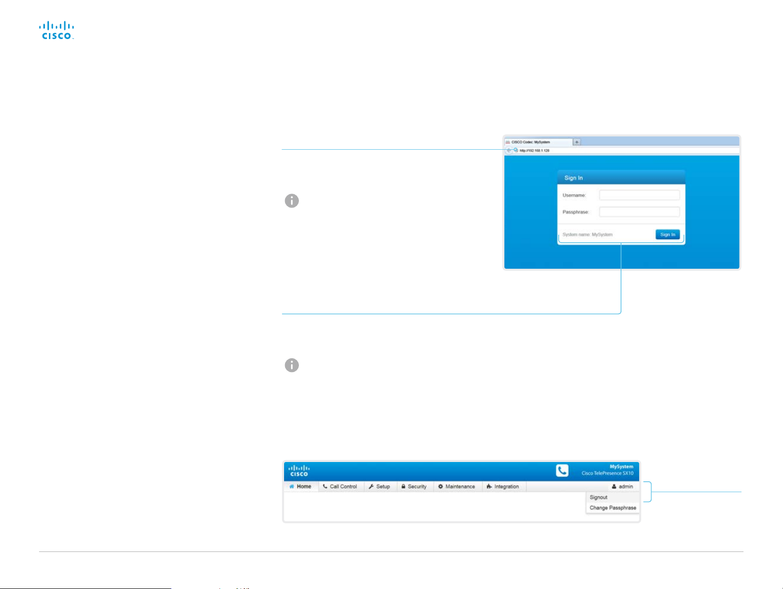
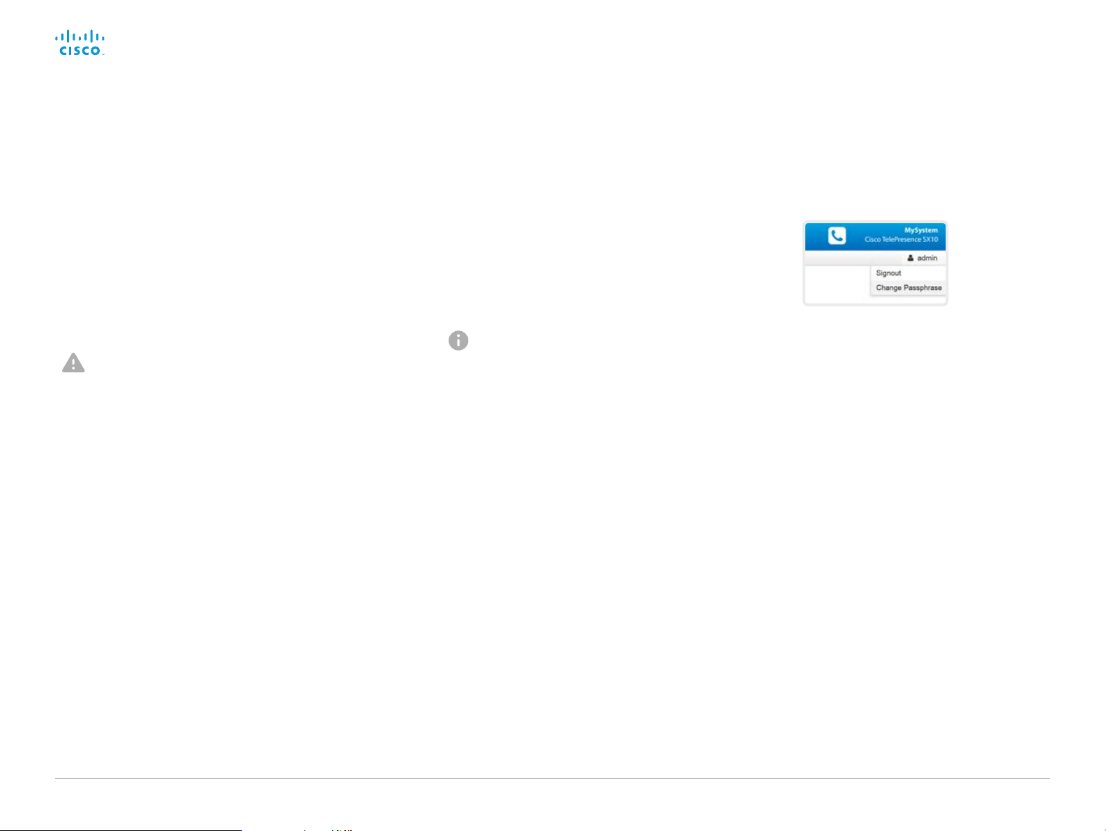
Sign in
Enter user name and passphrase for the endpoint and
click Sign In.
The system is delivered with a default user
named admin with no passphrase. Leave the
Passphrase field blank when signing in for the
first time.
It is mandatory to set a password for the
admin us er.
Sign out
Hover the mouse over
the user name and
choose Signout from
the drop-down list.
D153 30. 05 SX10 Administrator Guide CE9.0, APRIL 2017. www.cisco.com — Copyright © 2017 Cisco Systems, Inc. A ll rights reserved.
13
Page 14
Cisco TelePresence SX10 Quick Set Administrator Guide
Introduction
Configuration
Peripherals
Maintenance
System settings
Appendices
Introduction
How to administer the video system (page 3 of 4)
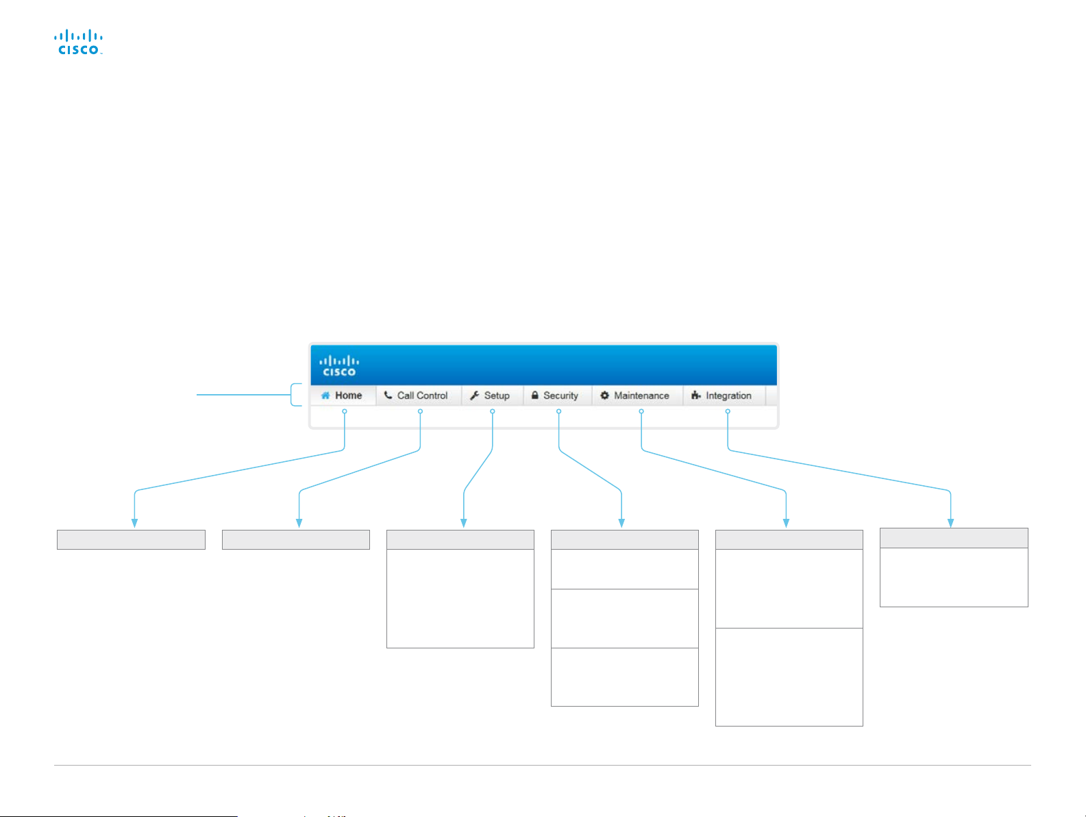
How the web interface is organized
The web interface is organized in sub-pages. All sub-pages
shown below are available if the video system is registerd to an
on-premise service (CUCM, VCS); the pages shown in grey color
are not available if the video system is registered to the Cisco
cloud service (Cisco Spark).
In both cases, a user that is signed in, sees only the pages that he
has access rights for.
Read more about user administration, user roles and access
rights in the ► User administration ch apt er.
Main menu
Call ControlHome Security
D153 30. 05 SX10 Administrator Guide CE9.0, APRIL 2017. www.cisco.com — Copyright © 2017 Cisco Systems, Inc. A ll rights reserved.
Setup
Configuration
Status
Peripherals
Personalization
Favorites
Users
Access PIN
Server Certificates
CUCM Certificates
Certificate Authorities
Strong Security Mode
Sign In Banner
Non-persistent Mode
14
Maintenance
Diagnostics
System Logs
Call Logs
User Interface Screenshots
Software Upgrade
Option Keys
Backup and Restore
System Recovery
Restart
Integration
In-Room Control
Startup Scripts
Developer API
Page 15

Cisco TelePresence SX10 Quick Set Administrator Guide
Introduction
Configuration
Peripherals
Maintenance
System settings
Appendices
Introduction
How to administer the video system (page 4 of 4)
Settings available on the user interface
You have access to some basic configurations and system tests
on the video system’s user interface. Some of the configurations
and tests may be unavailable due to the actual system setup.
• Change the language
• Change the time zone
• Adjust the screen (overscan compensation)
• Change the network settings for the video system
• Change the network settings for the Touch controller
• Select and activate a ser vice (Cisco’s cloud service, or Cisco
UCM, VCS or Expressway on-premise services)
• Check the microphone level
• Run a sytem volume check, and set the default volume
• Set the default camera position
• Check the connection to a presentation source
• View system diagnostics for troubleshooting
• Unpair the Touch controller from the video system, and select
another system to pair with
• Factory reset the video system
• Enable extended logging
Most of these settings and tests are also part of the Setup
assistant that is launched when the video system is powered up
for the first time. The Setup assistant is described in the Getting
Started Guide for systems running CE software.
Access Settings
1. Select the settings icon (cogwheel) in the status bar of the
user interface.
2. Select System information > Settings.
You may set a PIN code to protect the Settings menu, refer to
the ► Set a PIN code for the Settings menu ch apt er.
3. Select the button next to the setting you want to change or
the test you want to run.
D153 30. 05 SX10 Administrator Guide CE9.0, APRIL 2017. www.cisco.com — Copyright © 2017 Cisco Systems, Inc. A ll rights reserved.
15
Page 16

Cisco TelePresence SX10 Quick Set Administrator Guide
Introduction
Configuration
Peripherals
Maintenance
System settings
Appendices
Configuration
Chapter 2
Configuration
D153 30. 05 SX10 Administrator Guide CE9.0, APRIL 2017. www.cisco.com — Copyright © 2017 Cisco Systems, Inc. A ll rights reserved.
16
Page 17

Cisco TelePresence SX10 Quick Set Administrator Guide
Introduction
Configuration
Peripherals
Maintenance
System settings
Appendices
Configuration
User administration
You have to sign in to get access to the web and command line
interfaces. You can assign different roles to users, to determine
what they should have access to.
The default user account
The video system comes with a default administrator user
account with full access rights. The user name is admin and no
passphrase is initially set.
It is mandatory to set a passphrase for the admin us er.
Read how to set the passphrase in the ► Change the system
passphrase ch apter.
Create a new user account
1. Sign in to the web interface, and navigate to Security > Users.
2. Click Add new user....
3. Fill in the Username, Passphrase and Repeat passphrase
fields.
As a default, the user has to change the passphrase when he
signs in for the first time.
Fill in the Client Certificate DN (Distinguished Name) field only
if you use client certificates for authentication.
4. Check the appropriate Roles check boxes.
If you assign the ADMIN role to a user, enter your own
passphrase in the Your passphrase input field for verification.
5. Set the Status to Active to activate the user.
6. Click Create User.
Use the Back button to leave without making any changes.
input
Edit an existing user account
If you make changes to a user that holds the Admin role, you must
always enter your own passphrase in the Your passphrase input
field for verification.
Change the user privileges
1. Sign in to the web interface, and navigate to
Security > Users.
2. Click the appropriate user in the list.
3. Choose user roles, set the status to Acitve or
Inactive, and decide if the user has to change the
passphrase on the next sign in.
Fill in the Client Certificate DN (Distinguished
Name) field only if you use certificate login on
HTTPS.
4. Click Edit User to save the changes.
Use the Back button to leave without making any changes.
Change the passphrase
1. Sign in to the web interface, and navigate to Security > Users.
2. Click the appropriate user in the list.
3. Enter the new passphrase in the appropriate input fields.
4. Click Change passphrase to save the change.
Use the Back button to leave without making any changes.
Delete the user account
1. Sign in to the web interface, and navigate to Security > Users.
2. Click the appropriate user in the list.
3. Click Delete user... and confirm when prompted.
About user roles
A user account may hold one or a
combination of user roles. A user account
with full access rights, like the default
admin user, should possess the ADMIN,
USER and AUDIT roles.
These are the user roles:
ADMIN: A user with this role can create
new users, change most settings, make
calls, and search the contact lists. The
user cannot upload audit certificates and
change the security audit settings.
USER: A user with this role can make
calls and search the contact lists. The
user can modify a few settings, for
example adjust the ringtone volume and
set the time and date format.
AUDIT: A user with this role can change
the security audit settings and upload
audit certificates.
ROOMCONTROL: A user with this role
can create in-room controls. The user
has access to the In-room control editor
and corresponding developement tools.
INTEGRATOR: A user with this role has
access to settings, commands and status
that are required to set up advanced AV
scenarios, and to integrate our video
systems with 3
user can also create in-room controls.
Cisco Spark registered systems
If a video system is registered to Cisco’s
could service (Cisco Spark), only
local users with the INTEGRATOR and
ROOMCONTROL user roles are available.
rd
party equipment. Such a
D153 30. 05 SX10 Administrator Guide CE9.0, APRIL 2017. www.cisco.com — Copyright © 2017 Cisco Systems, Inc. A ll rights reserved.
17
Page 18
Cisco TelePresence SX10 Quick Set Administrator Guide
Introduction
Configuration
Peripherals
Maintenance
System settings
Appendices
Configuration
Change the system passphrase
You need to know the system passphrase in order to:
• Sign in to the web interface
• Sign in and use the command line interfaces
The default user account
The video system is delivered with a default user account with
full access rights. The user name is admin, and initially, no
passphrase is set.
It is mandatory to set a passphrase for the default admin
user in order to restrict access to system configuration. It
is also mandatory to set a passphrase for any other user
with ADMIN rights.
A warning, saying that the system passphrase is not set, is shown
on screen until a passphrase is set for the admin us er.
Other user accounts
You can create many user accounts for the video system.
Read more about how to create and manage user accounts in the
► User administration ch a pter.
Change your passphrase
1. Sign in to the web interface, hover the mouse over the user
name, and choose Change Passphrase in the drop down list.
2. Enter the current passphrase and new passphrase in the input
fields, and click Change passphrase.
The passphrase format is a string with 0–64 characters.
If the passphrase currently is not set, leave the Current
passphrase field blank.
Change another user’s passphrase
If you have administrator access rights, you can change the
password of any user.
1. Sign in to the web interface, and navigate to Security > Users.
2. Click the appropriate user in the list.
3. Enter the new passphrase in the Passphrase and Repeat
passphrase input fields.
If the user holds the Admin role, you must enter your own
passphrase in the Your passphrase input field for verification.
4. Click Change passphrase to save the change.
Use the Back button to leave without making any changes.
D153 30. 05 SX10 Administrator Guide CE9.0, APRIL 2017. www.cisco.com — Copyright © 2017 Cisco Systems, Inc. A ll rights reserved.
18
Page 19

Cisco TelePresence SX10 Quick Set Administrator Guide
Introduction
Configuration
Peripherals
Maintenance
System settings
Appendices
Configuration
Set a PIN code for the Settings menu
When you use the TRC6 remote control, you have access to an
on-screen Settings menu.
We recommend that you set a PIN code for the Settings menu, to
prevent unauthorized users from changing the configuration of the
video system.
Set a PIN code
1. Sign in to the web interface, and navigate to
Security > Access PIN.
2. Enter a PIN code in the input field, and click Set PIN.
The PIN can only contain numbers.
Clear the PIN code
1. Sign in to the web interface, and navigate to
Security > Access PIN.
2. Click Clear PIN.
D153 30. 05 SX10 Administrator Guide CE9.0, APRIL 2017. www.cisco.com — Copyright © 2017 Cisco Systems, Inc. A ll rights reserved.
19
Page 20
Cisco TelePresence SX10 Quick Set Administrator Guide
Introduction
Configuration
Peripherals
Maintenance
System settings
Appendices
Configuration
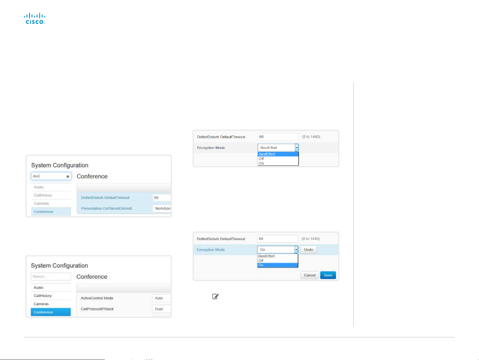
System configuration
Sign in to the web interface, and navigate to Setup >
Configuration.
Find a system setting
Search for settings
Enter as many letters as needed in the search field. All settings
that contain these letters are shown in the right pane. Settings
that have these letters in their value space are also shown.
Select a category and navigate to settings
The system settings are grouped in categories. Choose a
category in the left pane to show the associated settings.
Change a system setting
Check the value space
A settings’s value space is specified either by text following
the input field or in a drop-down list that opens when you
click the arrow.
Change a value
1. Choose the preferred value from the drop-down list, or
enter new text in the input field.
2. Click Save for the change to take effect.
Use the Undo or Cancel buttons if you do not want to
make any changes.
About system settings
All system settings can be changed from
the web interface.
Each system setting is described in the
► System settings chap ter.
Different settings may require different
user credentials. In order to be sure that
an administrator is able to change all
system settings, an administrator user
must possess all user roles.
You can read more about user
administration and user roles in the
► User administration ch a pter.
Categories with unsaved changes are marked with an edit
symbol (
D153 30. 05 SX10 Administrator Guide CE9.0, APRIL 2017. www.cisco.com — Copyright © 2017 Cisco Systems, Inc. A ll rights reserved.
).
20
Page 21
Cisco TelePresence SX10 Quick Set Administrator Guide
Introduction
Configuration
Peripherals
Maintenance
System settings
Appendices
Configuration
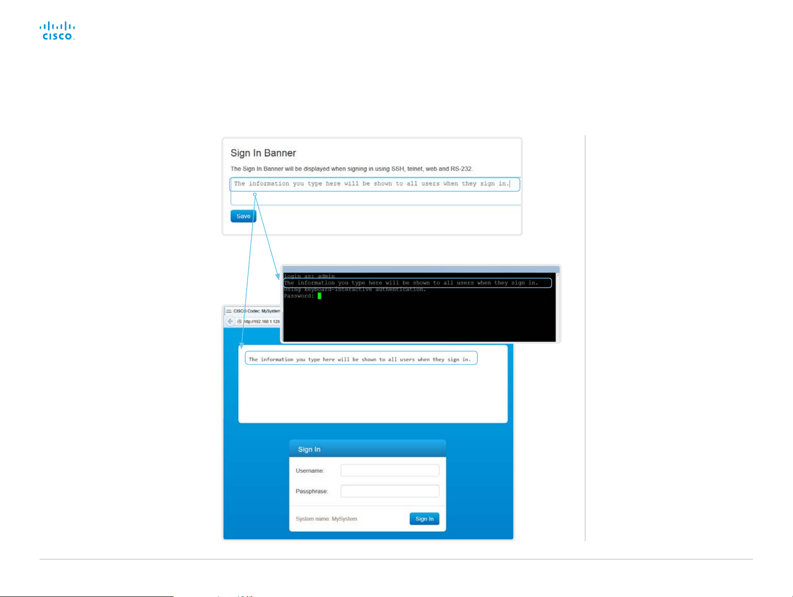
Add a sign in banner
Sign in to the web interface, and navigate
to Security > Sign In Banner.
1. Enter the message that you want to
present to the user when he signs in.
2. Click Save to activate the banner.
About sign in banner
If a system administrator wants to provide
initial information to all users, he can
create a sign in banner. The message is
shown when the user signs in to the web
interface or the command line interface.
D153 30. 05 SX10 Administrator Guide CE9.0, APRIL 2017. www.cisco.com — Copyright © 2017 Cisco Systems, Inc. A ll rights reserved.
21
Page 22
Cisco TelePresence SX10 Quick Set Administrator Guide
Introduction
Configuration
Peripherals
Maintenance
System settings
Appendices
Configuration
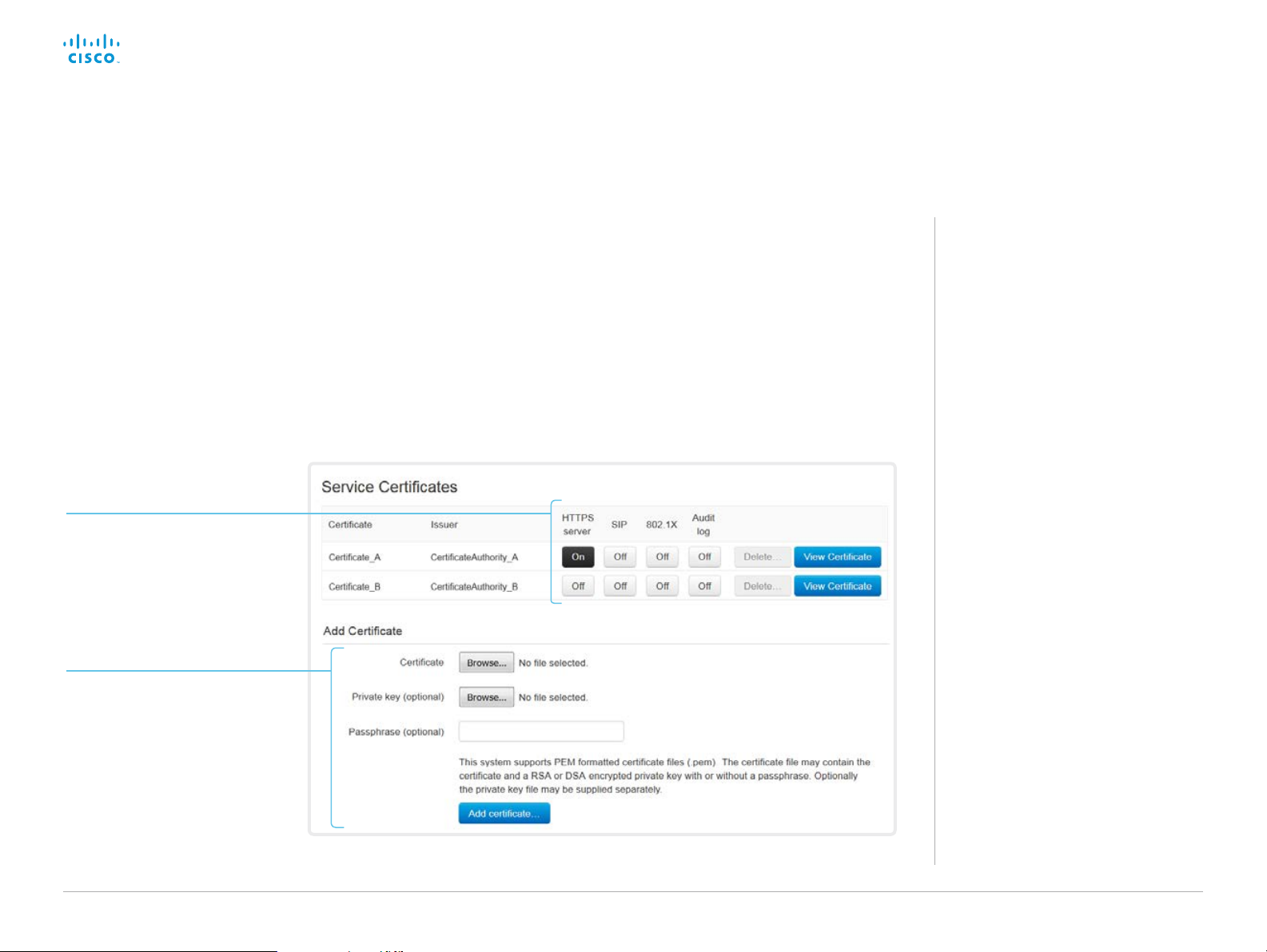
Manage the service certificates of the video system
Sign in to the web interface and navigate to Security > Service
Certificates.
Enable or disable, view or
delete a certificate
Use the On and Off buttons to
enable or disable a certificate for
the different services.
Use the corresponding button to
view or delete a certificate.
Add a certificate
You need the following files:
• Certificate (file format: .PEM)
• Private key, either as a separate file or included in the same
file as the certificate (file format: .PEM format)
• Passphrase (required only if the private key is encrypted)
The certificate and the private key will be stored in the same file
on the video system.
About the service
certificates of the video
system
Certificate validation may be required
when using TLS (Transport Layer
Security).
A server or client may require that the
video system presents a valid certificate
to them before communication can be
set up.
The video system’s certificates are text
files that verify the authenticity of the
system. These certificates may be issued
by a certificate authority (CA).
Certificates are used for the following
services: HTTPS server, SIP, IEEE 802.1X
and audit logging.
You can store many certificates on the
video system, but only one certificate can
be enabled for each service at a time.
If authentication fails, the connection will
not be established.
1. Browse to find the Certificate
file and Private key file (optional)
on your computer.
2. Fill in the Passphrase if required.
3. Click Add certificate... to store
the certificate on the video
system.
The cer tificates and certificate issuers in the illustration are examples. Your system has other certificates.
D153 30. 05 SX10 Administrator Guide CE9.0, APRIL 2017. www.cisco.com — Copyright © 2017 Cisco Systems, Inc. A ll rights reserved.
22
Page 23
Cisco TelePresence SX10 Quick Set Administrator Guide
Introduction
Configuration
Peripherals
Maintenance
System settings
Appendices
Configuration
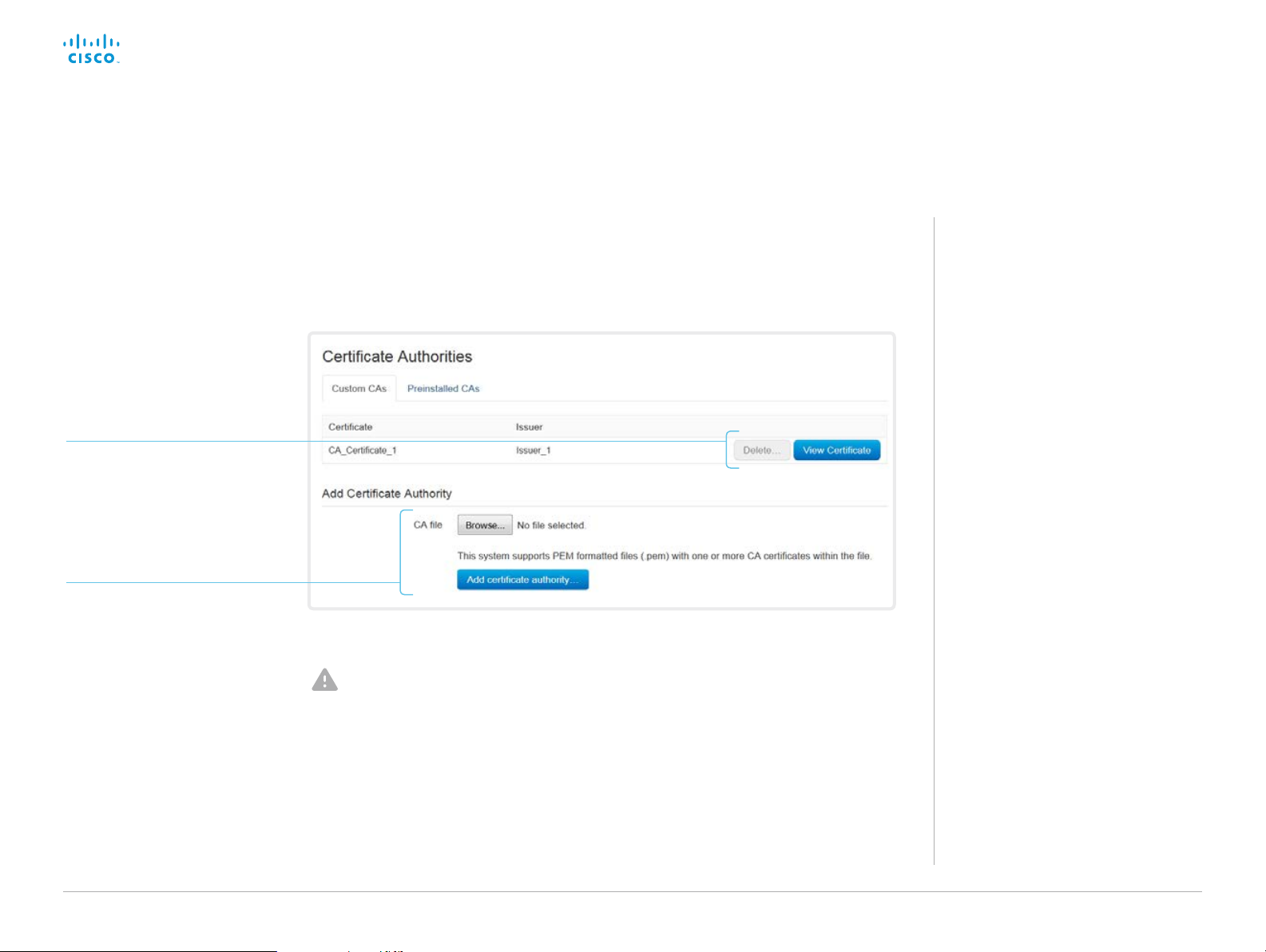
Manage the list of trusted certificate authorities (CAs)
Sign in to the web interface, navigate to Security > Certificate
Authorities, and open the Custom CAs tab.
View or delete a certificate
Use the corresponding button to
view or delete a certificate.
Upload a list of
certificate authorities
1. Browse to find the file
containing a list of CA
certificates on your computer
(file format: .PEM).
2. Click Add certificate authority...
to store the new CA certificates
on the video system.
The cer tificates and certificate issuers in the illustration are examples. Your system has other certificates.
Previously stored certificates are not deleted
automatically.
The entries in a new file with CA certificates
are appended to the existing list.
You need the following file:
• CA certificate list (file format: .PEM).
About trusted CAs
Certificate validation may be required
when using TLS (Transport Layer
Security).
The video system may be set up to
require that a server or client presents
its certificate to the video system before
communication can be set up.
The certificates are text files that verify
the authenticity of a server or client. The
certificates must be signed by a trusted
CA.
In order to verify the signature of the
certificates, a list of trusted CAs must
reside on the video system.
The list must include all CAs needed in
order to verify certificates for both audit
logging and other connections.
If authentication fails, the connection will
not be established.
D153 30. 05 SX10 Administrator Guide CE9.0, APRIL 2017. www.cisco.com — Copyright © 2017 Cisco Systems, Inc. A ll rights reserved.
23
Page 24
Cisco TelePresence SX10 Quick Set Administrator Guide
Introduction
Configuration
Peripherals
Maintenance
System settings
Appendices
Configuration
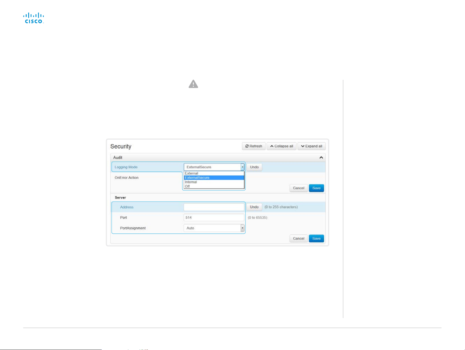
Set up secure audit logging
Sign in to the web interface, navigate to Setup > Configuration. The certificate authority (CA) that verifies the certificate
of the audit server must be in the video system’s list of
trusted certificate authorities. Otherwise, logs will not be
sent to the external server.
Refer to the ► Manage the list of trusted certificate
authorities (CAs) chapter how to update the list.
1. Open the Security category.
2. Find the Audit > Server
settings, and enter the
Address of the audit server.
If you set PortAssignment to
Manual, you must also enter
a Port number for the audit
server.
Click Save for the changes
to take effect.
3. Set Audit > Logging > Mode
to ExternalSecure.
Click Save for the change to
take effect.
About secure audit logging
When audit logging is enabled, all sign in
activity and configuration changes on the
video system are recorded.
Use the Security > Audit > Logging >
Mode setting to enable audit logging.
Audit logging is disabled by default.
In ExternalSecure audit logging mode
the video system sends encrypted audit
logs to an external audit server (syslog
server), which identity must be verified by
a signed certificate.
The signature of the audit server is
verified using the same CA list as other
servers/clients.
If the audit server authentication fails, no
audit logs are sent to the external server.
D153 30. 05 SX10 Administrator Guide CE9.0, APRIL 2017. www.cisco.com — Copyright © 2017 Cisco Systems, Inc. A ll rights reserved.
24
Page 25
Cisco TelePresence SX10 Quick Set Administrator Guide
Introduction
Configuration
Peripherals
Maintenance
System settings
Appendices
Configuration
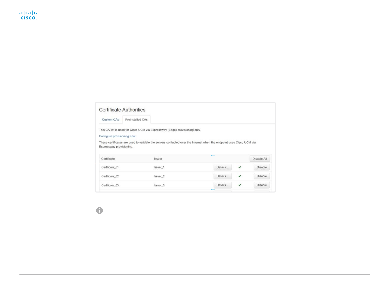
Manage pre-installed certificates for CUCM via Expressway provisioning
Sign in to the web interface, navigate to Security > Certificate
Authorities, and open the Preinstalled CAs tab.
View or disable certificates
Use the Details... and Disable
buttons respectively, to view or
disable certificates.
The cer tificates and certificate issuers in the illustration are examples. Your system has other certificates.
As an alternative to using the pre-installed certificates, you
can append the certificates you need to the certificate list
manually.
Refer to the ► Manage the list of trusted certificate
authorities (CAs) chapter how to update the list of trusted
certificates.
About pre-installed
certificates
The pre-installed certificates in this
list are only used when the video
system is provisioned by Cisco Unified
Communications Manager (CUCM) via
Expressway (Edge).
Only Cisco Expressway infrastructure
certificates are checked against this list.
If the validation of the Cisco Expressway
infrastructure certificate fails, the video
system will not be provisioned and
registered.
Factory resetting the video system
does not delete the list of pre-installed
certificates.
D153 30. 05 SX10 Administrator Guide CE9.0, APRIL 2017. www.cisco.com — Copyright © 2017 Cisco Systems, Inc. A ll rights reserved.
25
Page 26

Cisco TelePresence SX10 Quick Set Administrator Guide
Introduction
Configuration
Peripherals
Maintenance
System settings
Appendices
Configuration
Delete CUCM trust lists
The information in this chapter is only relevant for video systems
that are registered to a Cisco Unified Communications Manager
(CUCM).
Sign in to the web interface, navigate to Security >
CUCM Certificates.
Delete the CUCM trust lists
Click Delete CTL/ITL to remove the trust lists.
As a general rule, you should not delete old CTL
(Certificate Trust List) and ITL (Initial Trust List) files.
In these cases, you must still delete them:
• When you change the CUCM IP address.
• When you move the endpoint between CUCM
clusters.
• When you need to re-generate or change the CUCM
certificate.
Overview of trust list fingerprints and certificates
The trust lists’ fingerprints and an overview of the certificates in
the lists are displayed on the web page.
This information may be useful for troubleshooting.
More information about trust
lists
For more information about CUCM and
trust lists, read the Deployment guide for
TelePresence endpoints on CUCM that is
available on the Cisco web site.
D153 30. 05 SX10 Administrator Guide CE9.0, APRIL 2017. www.cisco.com — Copyright © 2017 Cisco Systems, Inc. A ll rights reserved.
26
Page 27

Cisco TelePresence SX10 Quick Set Administrator Guide
Introduction
Configuration
Peripherals
Maintenance
System settings
Appendices
Configuration
Change the persistency mode
Sign in to the web interface and navigate to Security >
Non-persistent Mode.
Check the persistency status
The active radio buttons show the current persistency status of
the video system.
Alternatively, you can navigate to Setup > Status, and then open
the Security category to see the Persistency status.
Change the persistency settings
All persistency settings are set to Persistent by default. You only
have to change these settings if you want to make them Non-
persistent.
1. Click the radio buttons to set the persistency for
configurations, call history, internal logging, local phonebook
(local directory and favorites) and IP connectivity (DHCP)
information.
2. Click Save and re bo ot....
The video system restarts automatically. After the restart, the
behavior changes according to the new persistency settings.
Logs, configurations, and other data that was stored
before you switched to Non-persistent mode, are NOT
cleared or deleted.
Persistency mode
Configurations, call history, internal
logs, local phonebook (local directory
and favorites list), and IP connectivity
information are stored by default.
Because all persistency settings are set
to Persistent, a system restart does not
delete this information.
Generally, we recommend you NOT to
change the persistency settings. Only
change to Non-persistent mode if
you have to prevent users from being
able to see or traceback to any logged
information from the previous session
In Non-persistent mode, the following
information is lost or cleared each time
the system restarts:
• System configuration changes
• Information about placed and
reveived calls (call history)
• Internal log files
• Changes to the local contacts or
favorites list
• All IP related information (DHCP) from
the last session
Information that was stored before
changing to Non-persistent mode
is not automatically cleared or
deleted. You must factory reset
the video system to delete such
information.
There is more information about
performing a factor y reset in the
► Factory reset the video system
ch apter.
D153 30. 05 SX10 Administrator Guide CE9.0, APRIL 2017. www.cisco.com — Copyright © 2017 Cisco Systems, Inc. A ll rights reserved.
27
Page 28
Cisco TelePresence SX10 Quick Set Administrator Guide
Introduction
Configuration
Peripherals
Maintenance
System settings
Appendices
Configuration
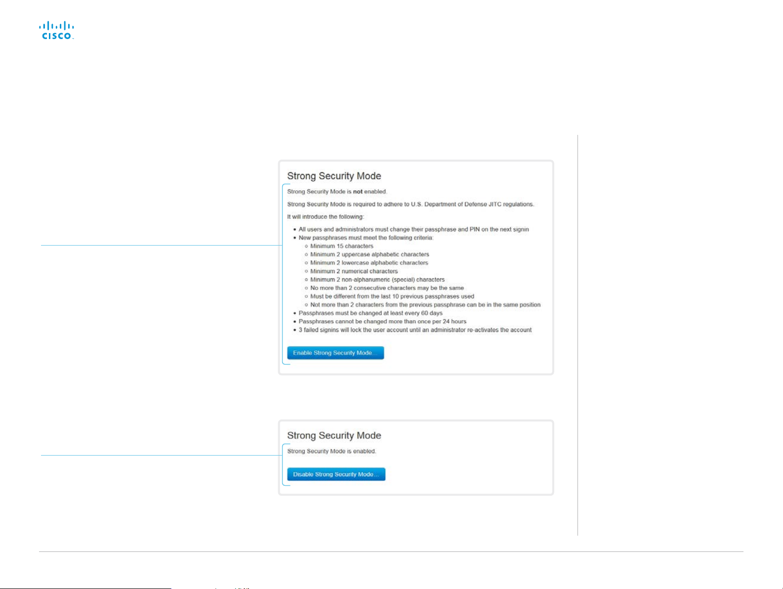
Set strong security mode
Sign in to the web interface, navigate to Security >
Strong Security Mode.
Set strong security mode
Read carefully about the consequences of strong
security mode before you continue.
1. If you want to use strong security mode, click
Enable Strong Security Mode.... and confirm
your choice in the dialog box that appears.
The video system restarts automatically.
2. Change the passphrase when you are
prompted. The new passphrase must meet the
strict criteria as described.
How to change the system passphrase is
described in the ► Change the system
passphrase ch apter.
About strong security mode
Use strong security mode only when
compliance with DoD JITC regulations is
required.
Strong security mode sets very strict
passphrase requirements, and requires all
users to change their passphrase on the
next sign in.
Return to normal mode
Click Disable Strong Security Mode... in order to
restore the video system to normal mode. Confirm
your choice in the dialog box that appears.
The video system restarts automatically.
D153 30. 05 SX10 Administrator Guide CE9.0, APRIL 2017. www.cisco.com — Copyright © 2017 Cisco Systems, Inc. A ll rights reserved.
28
Page 29
Cisco TelePresence SX10 Quick Set Administrator Guide
Introduction
Configuration
Peripherals
Maintenance
System settings
Appendices
Configuration
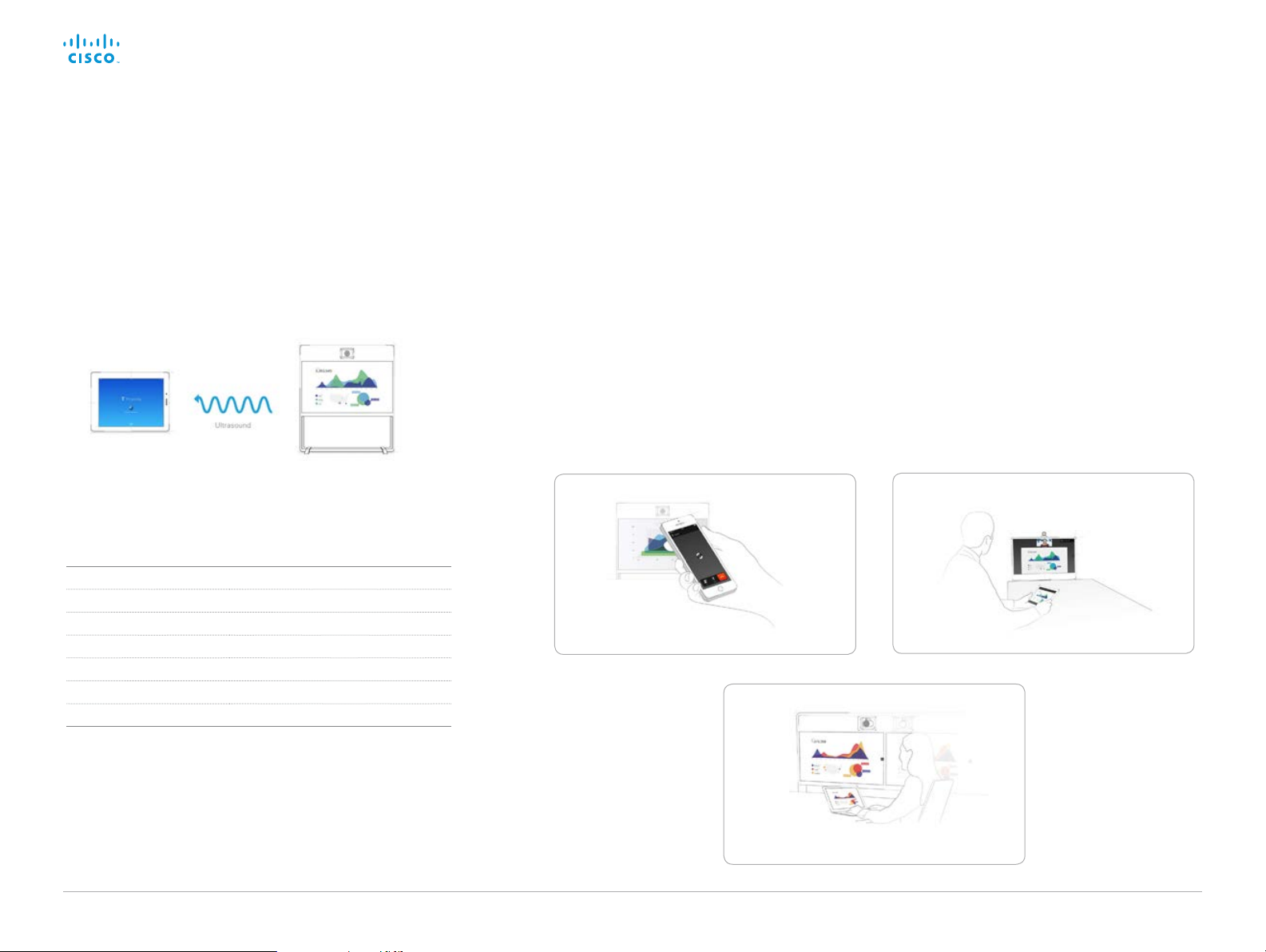
Set up Intelligent Proximity for content sharing (page 1 of 5)
Cisco Proximity allows users to see, control, capture and share
content directly on their own mobile devices (smartphone, tablet,
or laptop), when the device is near a video system.
The mobile device can automatically pair with the video system
when it comes within range of ultrasound transmitted by the video
system.
The number of simultaneous Proximity connections depends
on the type of video system. The client warns new users if the
maximum number of connections has been reached.
Video system Maximum number of connections
Spark Room Kit 7
SX80 10
SX20 7
SX10 7
MX700, MX800 10
MX200 G2, MX300 G2 7
DX70, DX80 3
Proximity services
Place calls and control the video system:
• Dial, mute, adjust volume, hang up
• Available on smartphones and tablets (iOS and Android)
View shared content on a mobile device:
• View shared content, review previous slides, save selected slides
• Available on smartphones and tablets (iOS and Android)
• For DX70 and DX80, this service is available only when in a call
Wireless share from a desktop client:
• Share content without connecting a presentation cable
• Available on laptops (OS X and Windows)
Place calls and control the video system
View shared content on a mobile device
Wireless share from a mobile device
D153 30. 05 SX10 Administrator Guide CE9.0, APRIL 2017. www.cisco.com — Copyright © 2017 Cisco Systems, Inc. A ll rights reserved.
29
Page 30

Cisco TelePresence SX10 Quick Set Administrator Guide
Introduction
Configuration
Peripherals
Maintenance
System settings
Appendices
Configuration
Set up Intelligent Proximity for content sharing (page 2 of 5)
Install a Cisco Proximity client
Where to find the clients
You can download the Cisco Proximity clients for smartphones
and tablets (Android and iOS), and laptops (Windows and OS X)
free of charge from ► http://proximity.cisco.com
Clients for smartphones and tablets are also available directly
through Google Play (Android) and Apple App Store (iOS).
End-user license agreement
Read the end-user license agreement carefully,
► http://www.cisco.com/c/en/us/td/docs/general/warranty/
English/EU1KEN_.html
Supported operating systems
• iOS 7 and above
• Android 4.0 and above
• Mac OS X 10.9 and above
• Windows 7 and above
The tile based interface introduced with Windows 8 is not
supported.
D153 30. 05 SX10 Administrator Guide CE9.0, APRIL 2017. www.cisco.com — Copyright © 2017 Cisco Systems, Inc. A ll rights reserved.
30
Page 31

Cisco TelePresence SX10 Quick Set Administrator Guide
Introduction
Configuration
Peripherals
Maintenance
System settings
Appendices
Configuration
Set up Intelligent Proximity for content sharing (page 3 of 5)
Ultrasound emission
Cisco video systems emit ultrasound as part of the Proximity
feature.
Use the Proximity > Mode setting to switch the Proximity feature and thereby also ultrasound emission - On and Off.
Most people are exposed to ultrasound more or less daily in many
environments, including industry, commercial applications and
home appliances.
Even if airborne ultrasound may cause subjective effects for some
individuals, it is very unlikely that any effects will occur for levels
below 75 dB.
Spark Room Kit, SX10N and MX Series:
• The ultrasound sound pressure level is below 75 dB at a
distance of 50 cm or more from the loudspeaker.
DX70 and DX80:
• The ultrasound sound pressure level is below 75 dB at a
distance of 20 cm or more from the loudspeaker.
SX10, SX20, and SX80:
• We are not able to control the ultrasound sound pressure
level because these systems emit ultrasound on third-party
loudspeakers.
The volume control on the loudspeaker itself, and the
Peripherals > Pairing > Ultrasound > Volume > MaxLevel
setting affect the ultrasound sound pressure level; the volume
control on the remote control or Touch controller does not
have any effect.
Headsets
Spark Room Kit, DX70, DX80, and SX10N:
You can always use a headset with these systems because:
• DX70 and DX80 have dedicated headset outputs, on which we
never emit ultrasound.
• Spark Room Kit and SX10N play ultrasound on their built-in
loudspeakers. Ultrasound is never emitted on the HDMI or
audio outputs.
SX10, SX20, SX80, and MX Series:
• We strongly recommend you to switch off ultrasound emission
if you use a headset with these video systems (set Proximity >
Mode to Off). Then you cannot use the Proximity feature.
Since these systems don’t have dedicated headset outputs,
we are not able to control the sound pressure level from the
connected headsets.
SX10 versus SX10N
Cisco TelePresence SX10 Quick Set
comes in two versions: SX10 and SX10N.
SX10N has a built-in loudspeaker for
ultrasound, while SX10 use the same
speakers (3
other audio signals.
Find which version you have
SX10 or SX10N is part of the following
strings:
• Check the PID field on the rating label
• Navigate to Setup > Status in the web
rd
party) for ultrasound as for
at the rear of the video system
interface and check the SystemUnit >
Hardware > UDI status.
D153 30. 05 SX10 Administrator Guide CE9.0, APRIL 2017. www.cisco.com — Copyright © 2017 Cisco Systems, Inc. A ll rights reserved.
31
Page 32

Cisco TelePresence SX10 Quick Set Administrator Guide
Introduction
Configuration
Peripherals
Maintenance
System settings
Appendices
Configuration
Set up Intelligent Proximity for content sharing (page 4 of 5)
Enable Proximity services
1. Sign in to the web interface, and navigate to Setup >
Configuration.
2. Go to Proximity > Mode, and switch Proximity On.
The video system star ts sending ultrasound pairing
messages.
3. Enable the services you want to allow. Only Wireless share
from a mobile device is enabled by default.
In order to fully utilise the Proximity functionality, we
recommend that you enable all services.
Place calls and control the video system:
• Go to Proximity > Services > CallControl and choose
Enabled.
View shared content on a mobile device:
• Go to Proximity > Services > ContentShare > FromClients
and choose Enabled.
Wireless share from a desktop client:
• Go to Proximity > Services > ContentShare > ToClients
and choose Enabled.
Temporarily disable the Proximity services
In sessions or meetings where you want to prevent devices in the
room from receiving content, you can use the video system’s user
interface to temporarily disable the Proximity services.
The video system will continue to transmit ultrasound
pairing messages during such sessions. This ensures that
clients will know about a nearby video system, and can
give the user an explanation why he cannot connect.
1. Select the settings icon (cogwheel) in the status bar of the
user interface to open the dropdown panel.
2. Switch Proximity on or off with the toggle button.
The Proximity indicator
You will see a Proximity indicator on the display when Proximity is
switched On, and at least one Proximity service is enabled.
The Proximity indicator has two states:
Proximity services are available for use.
Proximity services are temporarily disabled. Use the
toggle button in the settings dropdown panel to make
them available again.
About Proximity
The Proximity feature is switched Off by
default, because the use of third-party
speakers may need additional testing for
Proximity to work as expected. In rare
cases the ultrasound may cause audio
artifacts. If so, consider to decrease the
maximum ultrasound volume with the
Peripherals > Pairing > Ultrasound >
Volume > MaxLevel setting.
When Proximity is switched On, the
video system transmits ultrasound pairing
messages.
The ultrasound pairing messages are
received by nearby devices with Proximity
clients, and triggers the authentication
and authorization of the device.
Provided that you have verified that
Proximity is suitable in your setup,
Cisco recommends - for the best user
experience - that Proximity always is
switched On
In order to get full access to Proximity,
the Proximity services (Proximity >
Services > ...) must be Enabled as well.
*
.
*
SX10: We recommend not to use a headset, if
you have switched on Proximity (ultrasound).
SX10N: You can always use a headset.
D153 30. 05 SX10 Administrator Guide CE9.0, APRIL 2017. www.cisco.com — Copyright © 2017 Cisco Systems, Inc. A ll rights reserved.
32
Page 33

Cisco TelePresence SX10 Quick Set Administrator Guide
Introduction
Configuration
Peripherals
Maintenance
System settings
Appendices
Configuration
Set up Intelligent Proximity for content sharing (page 5 of 5)
Room considerations
Room acoustics
• Rooms with hard surfaces may cause challenges due to
severe audio reflections. Acoustical treatment of meeting
rooms is always highly recommended for the best meeting
experience as well as Intelligent Proximity performance.
• Cisco recommends only one video system with Intelligent
Proximity enabled in a room. Otherwise, interference is likely
to occur, which may lead to problems with device discovery
and session maintenance.
About privacy
In the Cisco Privacy statement and the Cisco Proximity
Supplement you find information about data collection in the
clients and privacy concerns that needs to be considered
when deploying this feature in the organization. Refer to:
► http://www.cisco.com/web/siteassets/legal/privacy.html
You can use the video system’s user interface to temporarily
disable the Proximity services. This is usful in sessions or
meetings where you want to prevent mobile devices in the room
from receiving content.
Basic troubleshooting
Cannot detect devices with Proximity clients
• Check if the video system is in standby mode. Ultrasound is
not transmitted if the speakers (for example a TV in standby
mode) are turned off. Applies only to SX10, not to SX10N.
• Check the speaker volume. The volume control on a speaker
itself (not the volume controlled with the remote control or
Touch 10) affects the ultrasound volume. If the volume is too
low, the listening devices cannot detect the ultrasound pairing
messages. Applies only to SX10, not to SX10N.
• Some Windows laptops are not able to record sound in the
ultrasound frequency range (20
to frequency limitations with the sound card, sound driver or
the internal microphone of the particular device. Refer to the
Support forum for more information.
Audio artifacts
• If you can hear audio artifacts, like humming or clipping noise,
decrease the maximum ultrasound volume (Peripherals >
Pairing > Ultrasound > Volume > MaxLevel).
Cannot share content from a laptop
• For content sharing to work, the video system and the laptop
must be on the same network. For this reason Proximity
sharing might fail if your video system is connected to
your company network via Expressway, and your laptop is
connected via VPN (VPN client dependent).
kHz-22 kHz). This can be due
Additional resources
Cisco Intelligent Proximity site:
► https://www.cisco.com/go/proximity
Support forum:
► https://www.cisco.com/go/proximitysupport
D153 30. 05 SX10 Administrator Guide CE9.0, APRIL 2017. www.cisco.com — Copyright © 2017 Cisco Systems, Inc. A ll rights reserved.
33
Page 34

Cisco TelePresence SX10 Quick Set Administrator Guide
Introduction
Configuration
Peripherals
Maintenance
System settings
Appendices
Configuration
Adjust the video quality to call rate ratio
Video input quality settings
When encoding and transmitting video there is a trade-off
between high resolution (sharpness) and high frame rate (motion).
The Video Input Connector n Quality setting must be set to
Motion for the optimal definition settings to take any effect. With
the video input quality set to Sharpness, the endpoint will transmit
the highest resolution possible, regardless of frame rate.
Optimal definition profile
The optimal definition profile should reflect the lighting conditions
in the video conferencing room and the quality of the camera
(video input source). The better the lighting conditions and the
better the quality of the camera, the higher the profile should be
used.
Generally, the Medium profile is recommended. However, if the
lighting conditions are very good, we recommend that you test
the endpoint on the various Optimal Definition Profile settings
before deciding on a profile. The High profile may be set in order
to increase the resolution for a given call rate.
Some typical resolutions used for different optimal definition
profiles, call rates and transmit frame rates are shown in the table.
The resolution and frame rate must be supported by both the
calling and called systems.
Resolutions and frame rate [w×h@fps] obtained for different optimal definition profiles and call rates
Call rate
[kbps]
128 32 0 ×18 0 @ 3 0 512×288 @20 512×28 8 @3 0
160 512×2 88@ 20 512×288 @30 640×360@30
224 512×288 @30 640×360@30 768×448@30
352 640×360@30 768×448@30 768×44 8@3 0
448 768×448@30 768×448@30 1024×576@30
576 768×448 @30 1024×576@30 12 8 0×72 0 @ 30
768 1024×576@3 0 128 0 ×720 @ 3 0 12 8 0×72 0 @ 30
108 8 1280×7 20@3 0 128 0 ×720 @30 12 80×7 2 0@30
1312 1280×7 20@3 0 128 0 ×720 @30 19 20×1 0 8 0@30
1696 1280×7 20@3 0 1 920 ×108 0@ 30 19 2 0×1 0 8 0 @30
2464 19 20×1 0 8 0@30 19 20×1 0 8 0@30 19 20×1 0 8 0@30
3072 19 20×1080@3 0 1 920 ×108 0@ 30 19 2 0×10 8 0 @30
Normal Medium High
H.264, maximum 30 fps
Sign in to the web interface and navigate to Setup > Configuration.
1. Go to Video > Input > Connector n > Quality and set the video
quality parameter to Motion (skip this step for Connector 1
(internal camera).
2. Go to Video > Input > Connector n > OptimalDefinition >
Profile and choose the preferred optimal definition profile.
D153 30. 05 SX10 Administrator Guide CE9.0, APRIL 2017. www.cisco.com — Copyright © 2017 Cisco Systems, Inc. A ll rights reserved.
34
Page 35

Cisco TelePresence SX10 Quick Set Administrator Guide
Introduction
Configuration
Peripherals
Maintenance
System settings
Appendices
Configuration
Packet loss resilience - ClearPath
ClearPath introduces several mechanisms for advanced packet
loss resilience. These mechanisms increase the experienced
quality when you use your video system in an error prone
environment.
ClearPath is a Cisco proprietary protocol. All endpoints running
CE software support ClearPath.
If the involved endpoints and infrastructure elements support
ClearPath, all packet loss resilience mechanisms are used in
point-to-point connections (including hosted conferences).
D153 30. 05 SX10 Administrator Guide CE9.0, APRIL 2017. www.cisco.com — Copyright © 2017 Cisco Systems, Inc. A ll rights reserved.
35
Page 36

Cisco TelePresence SX10 Quick Set Administrator Guide
Introduction
Configuration
Peripherals
Maintenance
System settings
Appendices
Configuration
Choose wallpaper
Sign in to the web interface, and navigate to Setup >
Personalization.
Choose wallpaper
Choose a wallpaper from the list.
The active wallpaper is highlighted.
Upload a custom wallpaper
Overwrites any old custom wallpaper.
1. Browse to find the custom wallpaper
image file.
2. Click Upload to save the file on the
video system.
Supported file formats: BMP, GIF,
JPEG, PNG
Maximum file size: 16 megapixels
The custom wallpaper is automatically
activated once uploaded.
About a custom wallpaper
If you want the company logo or another
custom picture as background on the
main display, you may upload and use a
custom wallpaper.
You can only store one custom wallpaper
on the video system at a time; a new
custom wallpaper overwrites the old one.
When you use a custom wallpaper, these
items are removed from the main display:
• The large clock
• The list of upcoming meetings
Delete the custom wallpaper
Delete fully removes the custom
wallpaper from the video system.
You have to upload it anew if you want
use it again.
D153 30. 05 SX10 Administrator Guide CE9.0, APRIL 2017. www.cisco.com — Copyright © 2017 Cisco Systems, Inc. A ll rights reserved.
36
Page 37

Cisco TelePresence SX10 Quick Set Administrator Guide
Introduction
Configuration
Peripherals
Maintenance
System settings
Appendices
Configuration
Choose a ringtone and set the ringtone volume
Sign in to the web interface, and navigate to Setup >
Personalization.
Change the ringtone
1. Choose a ringtone from the
drop-down list.
2. Click Save to make it the
active ringtone.
Set the ringtone volume
Use the slide bar to adjust the
ringtone volume.
About ringtones
A set of ringtones are installed on the
video system. Use the web interface to
chose a ringtone, and set the ringtone
volume.
You can play back the chosen ringtone
from the web interface. Note that the
ringtone will be played back on the video
system itself, and not on the computer
running the web interface.
Play back the ringtone
Click the play button ( ► ) to
play back the ringtone.
Use the stop button ( ) to
end the playback.
D153 30. 05 SX10 Administrator Guide CE9.0, APRIL 2017. www.cisco.com — Copyright © 2017 Cisco Systems, Inc. A ll rights reserved.
37
Page 38

Cisco TelePresence SX10 Quick Set Administrator Guide
Introduction
Configuration
Peripherals
Maintenance
System settings
Appendices
Configuration
Manage local contacts
Sign in to the web interface and navigate to
Setup > Local Contacts.
Import/Export contacts from file
Click Export to save the local contacts
in a file; and click Import to bring in
contacts from a file.
The current local contacts are
discarded when you import new
contacts from a file.
Add or edit a contact
1. Click Add contact to make a new
local contact, or click a contact’s
name followed by Edit contact.
2. Fill in or update the form that pops
up.
Choose a folder in the folder drop
down list in order to store the
contact in a sub-folder.
Click Add contact method and fill in
the new input fields if you want to
store more than one contact method
for the contact (for example video
address, telephone and mobile
number).
3. Click Save to store the local contact.
Delete a contact
1. Click a contacts name followed by
Edit contact.
2. Click Delete to remove the local
contact.
Add or edit a sub-folder
1. Click Add folder to make a new sub-folder, or
click one of the listed sub-folders followed by
Edit folder to change an existing sub-folder.
2. Fill in or update the form that pops up.
3. Click Save to create or update the folder.
Delete a sub-folder
1. Click a folder’s name followed by Edit folder.
2. Click Delete to remove the folder and all its
contacts and sub-folders. Confirm your choice
in the dialog that pops up.
Manage Favorites using the
the video system’s user
interface
Add a contact in the Favorites list
1. Select Call on the home screen.
2. Select the contact you want to add.
3. Select the three dots that appear
under the Call button on the contact
card (only required when using
remote control).
4. Select Add to favorites or Mark as
favorite.
The contact you add will be placed in the
top folder. You cannot select or create a
sub-folder.
Remove a contact from the
Favorites list
1. Select Call on the home screen.
2. Select the Favorites tab.
3. Select the contact you want to
remove.
4. Select the three dots that appear
under the Call button on the contact
card (only required when using
remote control).
5. Select Remove favorite or Unmark as
favorite.
D153 30. 05 SX10 Administrator Guide CE9.0, APRIL 2017. www.cisco.com — Copyright © 2017 Cisco Systems, Inc. A ll rights reserved.
38
Page 39

Cisco TelePresence SX10 Quick Set Administrator Guide
Introduction
Configuration
Peripherals
Maintenance
System settings
Appendices
Peripherals
Chapter 3
Peripherals
D153 30. 05 SX10 Administrator Guide CE9.0, APRIL 2017. www.cisco.com — Copyright © 2017 Cisco Systems, Inc. A ll rights reserved.
39
Page 40

Cisco TelePresence SX10 Quick Set Administrator Guide
Introduction
Configuration
Peripherals
Maintenance
System settings
Appendices
Peripherals
Extend the number of input sources
You can customize our touch user interfaces to include input
sources that are connected to a third-party external video switch.
The sources will appear and behave as any other video source
that is connected directly to the video system.
Architecture
You need a Cisco video system with a touch interface, a thirdparty control system, for example Crestron or AMX, and a thirdparty video switch. It is the control system, not the video system,
that controls the video switch.
When you program the control system you must use the video
system’s API (events and commands)
video switch and the controls on the touch interface. This way you
can synchronize what is shown and done on the user interface
with the actual state of the input sources.
Tou ch
interface
Video system
API
Control
system
*
in order to connect with the
PC
Apple T V
Third-party
video switch
Chromecast
User interface with multiple external input sources (example)
Oth er...
Consult the In-Room Control guide for full details about how to
extend the user interface, and how to use the video system’s API
to set it up. Go to:
► http://www.cisco.com/go/in-room-control-docs
D153 30. 05 SX10 Administrator Guide CE9.0, APRIL 2017. www.cisco.com — Copyright © 2017 Cisco Systems, Inc. A ll rights reserved.
40
*
You need a user that holds the ROOMCONTROL,
INTEGRATOR, or ADMIN user roles in order to
access the API commands that you need when
programming the control system.
Page 41

Cisco TelePresence SX10 Quick Set Administrator Guide
Introduction
Configuration
Peripherals
Maintenance
System settings
Appendices
Peripherals
Real-time communication requirements for displays
We have put in a lot of effort to minimize the camera to screen
delay on our video systems, and also to detect and compensate
for total delay between the audio and video components.
We recommend that you use displays with low delay to increase
the naturalness of communications. We also recommend that you
test a sample before ordering a large number of displays.
Delay through most displays is often very high (>100 ms) and is
therefore detrimental to real-time communication quality.
The following display settings may reduce the delay:
• Activate Game mode, PC mode or similar modes that are
designed to reduce the response time and normally also the
delay
• Deactivate motion smoothing, like Motion Flow, Natural Motion,
or any other video processing that introduces additional delay
• Deactivate advanced audio processing, like Virtual Surround
effects and Dynamic Compression, which will make any
acoustic echo canceller malfunction
• Change to a different HDMI input
D153 30. 05 SX10 Administrator Guide CE9.0, APRIL 2017. www.cisco.com — Copyright © 2017 Cisco Systems, Inc. A ll rights reserved.
41
Page 42

Cisco TelePresence SX10 Quick Set Administrator Guide
Introduction
Configuration
Peripherals
Maintenance
System settings
Appendices
Peripherals
Connect the Touch 10 controller
(page 1 of 2)
Tou c h 10 must be paired to the video system via the network (LAN).
This is referred to as remote pairing.
Connect Touch 10 to the video system via the
network (LAN)
Connect Touch 10 and the video system to network wall sockets or to
a network switch as illustrated.
Touch 10 set-up
Once Touch 10 is connected to power, the set-up procedure begins.
Follow the instructions on screen.
When the Select a room system screen appears, note the following:
• A list of video systems signalling that they are available for paring
will show up on the screen. Tap the name of the video system you
want to pair with.
Note that the following must be fulfilled for a video system to show
up in the list:
• The video system and Touch 10 must be on the same subnet.
• The video system must have been restarted within the last 10
minutes. If the video system does not appear in the list, try
restarting it.
• If the video system does not appear in the list of available systems,
enter its IP address or hostname in the input field. Tap Connect.
• You have to log in with username and passphrase for the paring
process to commence. Tap Login.
A user with the USER role is sufficient; you do not need the ADMIN
role to perform this task.
Read more about how to create a user account and assign a role
to it in the ► User administration c hap ter.
If Touch 10 needs software upgrade, new software will be downloaded
from the video system and installed on the unit automatically as part of
the set-up procedure. Touch 10 restarts after the upgrade.
Power
• 100-240 VAC
• 50/60 Hz
SWITCH
PoE
injector
Contact information
The video system’s
name or address is
displayed in the status
bar when Touch 10 is
successfully paired to
the video system.
AP
Standard Ethernet cable
Standard Ethernet cable
PoE rated Ethernet cable
The Ethernet connector
is behind the lid at the
rear of Touch 10.
2
Network (LAN)
Network (LAN)
1
If the network infrastructure provides
Power over Ethernet (PoE), you do not
need a PoE injector; Touch 10 should
be connected directly to the wall socket
(Ethernet switch) with a PoE rated
Ethernet cable.
For safet y, the PoE source must be in
the same building as Touch 10. The PoE
rated Ethernet cable can be up to 100 m
(330 ft).
2
SX10 can also be powered over Ethernet
if the network infrastructure supports
PoE. If so, you must use a PoE rated
cable.
1
D153 30. 05 SX10 Administrator Guide CE9.0, APRIL 2017. www.cisco.com — Copyright © 2017 Cisco Systems, Inc. A ll rights reserved.
42
Page 43
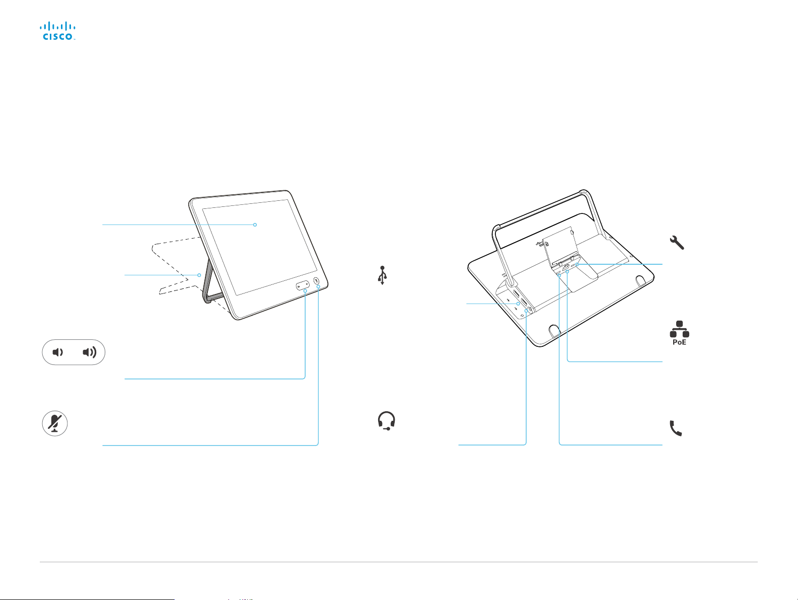
Cisco TelePresence SX10 Quick Set Administrator Guide
Introduction
Configuration
Peripherals
Maintenance
System settings
Appendices
Peripherals
Connect the Touch 10 controller (page 2 of 2)
Touch 10 physical interface
Touch screen
Adjustable support
to accommodate
individual ergonomic
needs
Sound bar for audio
adjustment
Audio mute
Two USB connectors
(not in use)
Mini-jack, 3.5 mm
(not in use)
Micro-USB:
for maintenance only
Ethernet with PoE:
for power and Ethernet
Not in use
D153 30. 05 SX10 Administrator Guide CE9.0, APRIL 2017. www.cisco.com — Copyright © 2017 Cisco Systems, Inc. A ll rights reserved.
43
Page 44

Cisco TelePresence SX10 Quick Set Administrator Guide
Introduction
Configuration
Peripherals
Maintenance
System settings
Appendices
Maintenance
Chapter 4
Maintenance
D153 30. 05 SX10 Administrator Guide CE9.0, APRIL 2017. www.cisco.com — Copyright © 2017 Cisco Systems, Inc. A ll rights reserved.
44
Page 45
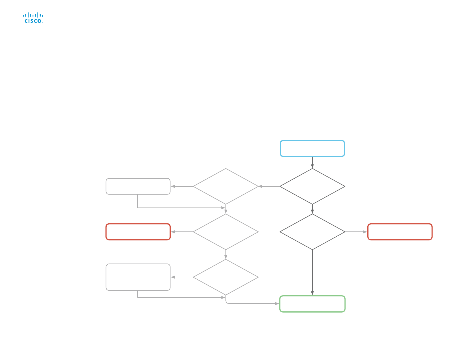
Cisco TelePresence SX10 Quick Set Administrator Guide
Introduction
Configuration
Peripherals
Maintenance
System settings
Appendices
Maintenance
Upgrade the system software (page 1 of 2)
Upgrading from TC to CE software
CE software is the evolution of TC software. We recommend
that you upgrade to TC7.3.6 or later before you upgrade to CE
soft ware.
It is impor tant that you read about upgrade requirements and
functionality changes before you upgrade to CE software.
Also check that your environment supports the changes. We
recommend reading the Software Release Notes carefully.
If you don’t take into account these considerations, upgrading to
CE can leave you with a non-functioning deployment that requires
you to downgrade.
Upgrade to TC7.3.6 or later
Use TC7.x software
Upgrading from CE8 to CE9
The MultiStream feature with Cisco TelePresence Server is
deprecated in CE9.
Also, some features that were available from the Touch controller
in CE8, are not available in the first CE9.0 release. Read the
Software Release Notes for details before you upgrade..
Install CE9?
No
Yes
Is your video
system running
TC7.3.6 or later?
Yes
Do you need TC
features that are
not supported in CE
softwar e?
*
TC
Which sof tware
version is the video
system running?
Do you need
MultiStream with
Cisco TelePresence
Server?
CE
Yes
Use CE8.x sof tware
No
Update your application
to the new API commands
*
CE software does not support the
following features and products:
- CTMS conferencing
- MediaNet
- Displays that do not support 16:9
resolution
D153 30. 05 SX10 Administrator Guide CE9.0, APRIL 2017. www.cisco.com — Copyright © 2017 Cisco Systems, Inc. A ll rights reserved.
before installing CE9
Yes
Are you currently
using the API (for
example Crestron or
AMX)?
No
45
No
Install CE9
Page 46

Cisco TelePresence SX10 Quick Set Administrator Guide
Introduction
Configuration
Peripherals
Maintenance
System settings
Appendices
Maintenance
Upgrade the system software (page 2 of 2)
Sign in to the web interface and navigate to Maintenance >
Software Upgrade.
Download new software
For software download, go to the Cisco Download
Software web page, and navigate to your product:
► http://www.cisco.com/cisco/software/navigator.html.
Each software version has a unique file name. The format of the
file name is “s52030ce9_0_ x .pkg ”.
Install new software
Download the appropriate software package and store it on your
computer. This is a .pkg file. Don’t change the file name.
1. Click Browse... and find the .pkg file that contains the new
soft ware.
The software version will be detected and shown.
About software versions
This video conference system is using CE
software. The version described in this
document is CE9.0.x.
Software release notes
For a complete overview of the news and changes, we
recommend reading the Software Release Notes (CE9).
Go to: ► http://www.cisco.com/c/en/us/support/
collaboration-endpoints/telepresence-quick-set-series/tsdproducts-support-series-home.html
2. Click Install software to start the installation process.
The complete installation normally take no longer than 15minutes.
You can follow the progress on the web page. The video system
restarts automatically after the installation.
You must sign in anew in order to continue working with the web
interface after the restart.
D153 30. 05 SX10 Administrator Guide CE9.0, APRIL 2017. www.cisco.com — Copyright © 2017 Cisco Systems, Inc. A ll rights reserved.
46
Check new software version
When you have selected a file, the
software version is shown here
Page 47
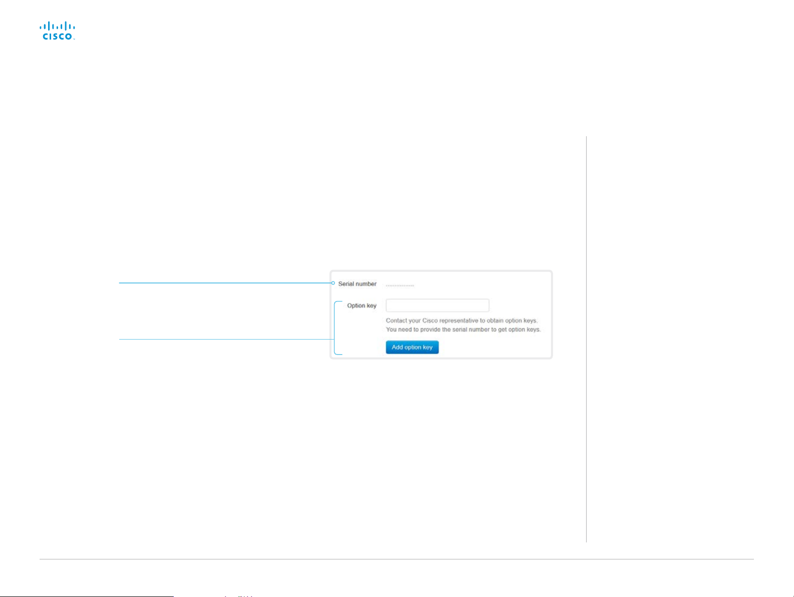
Cisco TelePresence SX10 Quick Set Administrator Guide
Introduction
Configuration
Peripherals
Maintenance
System settings
Appendices
Maintenance
Add option keys
Sign in to the web interface and navigate to Maintenance >
Option Keys.
You see a list of all option keys, also the ones that are not
installed on your video system.
Contact your Cisco representative for information about how to
get option keys for the uninstalled options.
The video system’s serial number
You need the video system’s serial number
when ordering an option key.
Add an option key
1. Enter an Option Key in the text input field.
2. Click Add option key.
If you want to add more than one option key,
repeat these steps for all keys.
About option keys
Your video system may or may not have
one or more software options installed. In
order to activate the optional functionality
the corresponding option key must be
present on the video system.
Each video system has unique option
keys.
Option keys are not deleted when
performing a software upgrade or factory
reset, so they need to be added only
once.
D153 30. 05 SX10 Administrator Guide CE9.0, APRIL 2017. www.cisco.com — Copyright © 2017 Cisco Systems, Inc. A ll rights reserved.
47
Page 48

Cisco TelePresence SX10 Quick Set Administrator Guide
Introduction
Configuration
Peripherals
Maintenance
System settings
Appendices
Maintenance
System status
System information overview
Sign in to the web interface to see the System Information page.
This page shows the product type, system name and basic
information about the hardware, software, installed options and
network address. Registration status for the video networks (SIP
and H.323) is included, as well as the number/URI to use when
making a call to the system.
Detailed system status
Sign in to the web interface, and navigate to Setup > Status in
order to find more detailed status information*.
Search for a status entry
Enter as many letters as needed in the search field. All entries that
contain these letters are shown in the right pane. Entries that have
these letters in their value space are also shown.
Select a category and navigate to the correct status
The system status is grouped in categories. Choose a category in
the left pane to show the related status to the right.
*
The status shown in the illustration serve as an example. The status of
your system may be different.
D153 30. 05 SX10 Administrator Guide CE9.0, APRIL 2017. www.cisco.com — Copyright © 2017 Cisco Systems, Inc. A ll rights reserved.
48
Page 49

Cisco TelePresence SX10 Quick Set Administrator Guide
Introduction
Configuration
Peripherals
Maintenance
System settings
Appendices
Maintenance
Run diagnostics
Sign in to the web interface and navigate to Maintenance >
Diagnostics.
The diagnostics page lists the status for some common
sources of errors
Errors and critical issues are clearly marked in red color;
warnings are yellow.
*
.
Run diagnostics
Click Re-run diagnostics to ensure that
the list is up to date.
Leave standby mode
Click Deactivate standby to wake up a
video system that is in standby mode.
*
The mes sages shown in the illustration ser ve as examples. Your system
may show other information.
D153 30. 05 SX10 Administrator Guide CE9.0, APRIL 2017. www.cisco.com — Copyright © 2017 Cisco Systems, Inc. A ll rights reserved.
49
Page 50

Cisco TelePresence SX10 Quick Set Administrator Guide
Introduction
Configuration
Peripherals
Maintenance
System settings
Appendices
Maintenance
Download log files
Sign in to the web interface and navigate to
Maintenance > System Logs.
Download all log files
Click Download logs archive...
and follow the instructions.
An anonymized call history
is included in the log files by
default.
Use the drop down list if
you want to exclude the call
history from the log files, or
if you want to include the full
call history (non-anonymous
caller/callee).
Open/save one log file
Click the file name to open the
log file in the web browser;
right click to save the file on
the computer.
Start extended logging
Click Start extended logging....
Extended logging lasts for
3 or 10 minutes, depending
on whether full capture of
network traffic is included or
not.
Click Stop extended logging if
you want to stop the extended
logging before it times out.
As default, the network traffic
is not captured. Use the drop
down menu if you want to
include partial or full capture of
network traffic.
About log files
The log files are Cisco specific debug
files which may be requested by the
Cisco support organization if you need
technical support.
The current log files are time stamped
event log files.
All current log files are archived in a time
stamped historical log file each time the
video system restarts. If the maximum
number of historical log files is reached,
the oldest one will be overwritten.
Extended logging mode
Extended logging mode may be switched
on to help diagnose network issues and
problems during call setup. While in this
mode more information is stored in the
log files.
Extended logging uses more of the video
system’s resources, and may cause the
video system to under-perform. Only use
extended logging mode when you are
troubleshooting an issue.
Refresh a log file list
Click the refresh button for
Current logs or Historical logs
to update the corresponding
lists.
D153 30. 05 SX10 Administrator Guide CE9.0, APRIL 2017. www.cisco.com — Copyright © 2017 Cisco Systems, Inc. A ll rights reserved.
50
Page 51

Cisco TelePresence SX10 Quick Set Administrator Guide
Introduction
Configuration
Peripherals
Maintenance
System settings
Appendices
Maintenance
Create a remote support user
Sign in to the web interface, navigate to Maintenance > System
Recovery and select the Remote Support User tab.
The remote support user should only be enabled for
troubleshooting reasons when instructed by Cisco TAC.
Create remote support user
1. Click Create user.
2. Open a case with Cisco TAC.
3. Copy the text in the To ke n field and send
it to Cisco TAC.
4. Cisco TAC will generate a password.
The remote support user is valid for seven
days, or until it is deleted.
About the remote support
user
In cases where you need to diagnose
problems on the video system you can
create a remote support user.
The remote support user is granted read
access to the system and has access to
a limited set of commands that can aid
troubleshooting.
You will need assistance from Cisco
Technical Assistance Center (TAC) to
acquire the password for the remote
support user.
Delete remote support user
Click Delete user.
D153 30. 05 SX10 Administrator Guide CE9.0, APRIL 2017. www.cisco.com — Copyright © 2017 Cisco Systems, Inc. A ll rights reserved.
51
Page 52

Cisco TelePresence SX10 Quick Set Administrator Guide
Introduction
Configuration
Peripherals
Maintenance
System settings
Appendices
Maintenance
Backup or restore a configuration
Sign in to the web interface and navigate to Maintenance >
Backup and Restore.
Show the current configuration
Click Preview backup to display the current settings on-screen.
Back up the current configuration
Click Take backup to store the configuration as a text file.
Restore configuration from backup
1. Click Browse... and find the backup file with the configuration
you want to restore.
2. Click Restore to reconfigure the system as defined in the file.
Some settings require that you restart the video system
before they take effect.
About configuration backup
All the system settings, which are
available on the System configuration
page, can be listed on-screen or stored
as a backup text file.
The backup text file can be loaded back
onto the system, thereby restoring the
configuration.
We do not recommend that you
load back a backup text file from
TC software, onto a video system
that is running CE software.
The configuration of the video
system is likely to be incomplete,
due to the differences between
the two software generations.
D153 30. 05 SX10 Administrator Guide CE9.0, APRIL 2017. www.cisco.com — Copyright © 2017 Cisco Systems, Inc. A ll rights reserved.
52
Page 53

Cisco TelePresence SX10 Quick Set Administrator Guide
Introduction
Configuration
Peripherals
Maintenance
System settings
Appendices
Maintenance
Revert to the previously used software image
Sign in to the web interface and navigate to Maintenance >
System Recovery.
We recommend you to back up the log files and configuration
of the video system before you swap to the previously used
software image.
Back up log files and system configuration
1. Select the Backup tab.
2. Click Download Logs and follow the instructions to save the
log files on your computer.
3. Click Download Configuration Backup and follow the
instructions to save the configuration file on your computer.
Revert to the previously used software image
Only administrators, or when in contact with Cisco technical
support, should perform this procedure.
1. Select the Software Recovery Swap tab.
2. Click Switch to software: cex.y.z..., where x.y.z indicates the
software version.
3. Click Yes to confirm your choice, or Cancel if you have
changed your mind.
Wait while the system resets. The system restarts automatically
when finished. This procedure may take a few minutes.
About the previously used
software image
If there is a severe problem with the video
system, switching to the previously used
software image may help solving the
problem.
If the system has not been factory reset
since the last software upgrade, the
previously used software image still
resides on the system. You do not have to
download the software again.
D153 30. 05 SX10 Administrator Guide CE9.0, APRIL 2017. www.cisco.com — Copyright © 2017 Cisco Systems, Inc. A ll rights reserved.
53
Page 54

Cisco TelePresence SX10 Quick Set Administrator Guide
Introduction
Configuration
Peripherals
Maintenance
System settings
Appendices
Maintenance
Factory reset the video system (page 1 of 3)
If there is a severe problem with the video system, the last resort
may be to reset it to its default factory settings.
It is not possible to undo a factory reset.
Always consider reverting to the previously used software
image before performing a factory reset. In many situations this
will recover the system. Read about software swapping in the
► Revert to the previously used software image ch apt er.
We recommend that you use the web interface or user interface
to factory reset the video system. If these interfaces are not
available, use the reset button.
A factory reset implies:
• Call logs are deleted.
• Passphrases are reset to default.
• All system parameters are reset to default values.
• All files that have been uploaded to the system are deleted.
This includes, but is not limited to, custom wallpaper,
certificates, and favorites lists.
• The previous (inactive) software image is deleted.
• Option keys are not affected.
The video system restarts automatically after the factory reset. It
is using the same software image as before.
We recommend that you back up the log files and configuration
of the video system before you perform a factory reset;
otherwise these data will be lost.
D153 30. 05 SX10 Administrator Guide CE9.0, APRIL 2017. www.cisco.com — Copyright © 2017 Cisco Systems, Inc. A ll rights reserved.
54
Page 55

Cisco TelePresence SX10 Quick Set Administrator Guide
Introduction
Configuration
Peripherals
Maintenance
System settings
Appendices
Maintenance
Factory reset the video system (page 2 of 3)
Factory reset using the web interface
We recommend that you back up the log files and configuration of
the video system before you continue with the factory reset.
Sign in to the web interface and navigate to Maintenance >
System Recovery.
1. Select the Factory Reset tab, and read the provided
information carefully.
2. Click Perform a factory reset....
3. Click Yes to confirm your choice, or Cancel if you have
changed your mind.
4. Wait while the video system reverts to the default factory
settings. When finished, the video system restarts
automatically. This may take a few minutes.
When the system has been successfully reset to factory
settings, the Setup assistant starts with the Welcome screen.
Factory reset from the user interface
We recommend that you back up the log files and configuration of
the video system before you continue with the factory reset.
1. Select the settings icon (cogwheel) in the status bar of the
user interface.
2. Select System information > Settings.
3. Select Reset system.
4. Click Reset to confirm your choice, or Back if you have
changed your mind.
5. Wait while the video system reverts to the default factory
settings. When finished, the video system restarts
automatically. This may take a few minutes.
When the system has been successfully reset to factory
settings, the Setup assistant starts with the Welcome screen.
Back up log files and system
configuration
Sign in to the web interface and navigate
to Maintenance > System Recovery.
Back up log files and system
configuration
1. Select the Backup tab.
2. Click Download Logs and follow the
instructions to save the log files on
your computer.
3. Click Download Configuration Backup
and follow the instructions to save the
configuration file on your computer.
D153 30. 05 SX10 Administrator Guide CE9.0, APRIL 2017. www.cisco.com — Copyright © 2017 Cisco Systems, Inc. A ll rights reserved.
55
Page 56

Cisco TelePresence SX10 Quick Set Administrator Guide
Introduction
Configuration
Peripherals
Maintenance
System settings
Appendices
Maintenance
Factory reset the video system (page 3 of 3)
Factory reset using the reset button
We recommend that you back up the log files and configuration of
the video system before you continue with the factory reset.
1. Lift the rubber flap on the back of the unit to uncover the reset
button (pin hole).
2. Use the tip of a pen (or similar) to press and hold the recessed
reset button until the screen turns black (approximately 10
seconds). Then release the button.
3. Wait while the video system reverts to the default factory
settings. When finished, the video system restarts
automatically. This may take a few minutes.
When the system has been successfully reset to factory
settings, the Setup assistant starts with the Welcome screen.
Reset button (pin hole)
The recessed button can
be quite difficult to use.
You should feel the button
go down when pushed.
Lift the rubber flap
to uncover the reset
button (pin hole).
D153 30. 05 SX10 Administrator Guide CE9.0, APRIL 2017. www.cisco.com — Copyright © 2017 Cisco Systems, Inc. A ll rights reserved.
56
Page 57

Cisco TelePresence SX10 Quick Set Administrator Guide
Introduction
Configuration
Peripherals
Maintenance
System settings
Appendices
Maintenance
Factory reset the Touch 10
In an error situation it may be required to factory reset the Touch
controller to recover connectivity. This should be done only when
in contact with the Cisco support organization.
When factory resetting the Touch controller the pairing
information is lost, and the Touch itself (not the video system) is
reverted to factory defaults.
It is not possible to undo a factory reset.
1. Locate the Mute and Volume down buttons.
2. Press and hold the Mute button until it starts blinking (red and
green). It takes approximately 10 seconds.
3. Press the Volume down button twice.
Touch 10 automatically reverts to the default factory settings
and restarts.
Touch 10 must be paired to the video system anew.
When successfully paired it receives a new configuration
automatically from the video system.
About pairing and how to
connect Touch 10 to the
video system
In order to use the Touch 10 controller,
Touch 10 must be paired to the codec via
LAN (remote pairing).
Read about pairing and how to connect
Touch 10 to the video system in the
► Connect the Touch 10 controller
ch apter.
Mute
Volume down
D153 30. 05 SX10 Administrator Guide CE9.0, APRIL 2017. www.cisco.com — Copyright © 2017 Cisco Systems, Inc. A ll rights reserved.
57
Page 58

Cisco TelePresence SX10 Quick Set Administrator Guide
Introduction
Configuration
Peripherals
Maintenance
System settings
Appendices
Maintenance
Capture user interface screenshots
Sign in to the web interface and navigate to Maintenance >
User Interface Screenshots.
Capture a screenshot
Click Take screenshot of Touch Panel to
capture a screenshot of the Touch controller,
or click Take screenshot of OSD to capture a
screenshot of the on-screen display.
The screenshot displays in the area below
the buttons. It may take up to 30 seconds
before the screenshot is ready.
All captured snapshots are included
in the list above the buttons. Click the
screenshot ID to display the image.
Delete screenshots
If you want to delete all screenshots,
click Remove all.
To delete just one screenshot, click
button for that screenshot.
the
×
About user interface
screenshots
You can capture screenshots both of
a Touch controller that is connected to
the video system, and of the on-screen
display (menus, indicators and messages
on the main display).
D153 30. 05 SX10 Administrator Guide CE9.0, APRIL 2017. www.cisco.com — Copyright © 2017 Cisco Systems, Inc. A ll rights reserved.
58
Page 59

Cisco TelePresence SX10 Quick Set Administrator Guide
Introduction
Configuration
Peripherals
Maintenance
System settings
Appendices
System settings
Chapter 5
System settings
D153 30. 05 SX10 Administrator Guide CE9.0, APRIL 2017. www.cisco.com — Copyright © 2017 Cisco Systems, Inc. A ll rights reserved.
59
Page 60

Cisco TelePresence SX10 Quick Set Administrator Guide
Introduction
Configuration
Peripherals
Maintenance
System settings
Appendices
System settings
Overview of the system settings
In the following pages you will find a complete list of the system
settings which are configured from the Setup > Configuration
page on the web interface.
Open a web browser and enter the IP address of the video
system then sign in.
How to find the IP address
1. Select the settings icon (cogwheel) in the status bar of
the user interface.
2. Select System Information.
Audio settings ................................................................................................................. 64
Audio DefaultVolume ........................................................................................................... 64
Audio Input Microphone [1..2] Mode ................................................................................... 65
Audio Input Microphone [2] EchoControl Dereverberation ................................................. 65
Audio Input Microphone [2] EchoControl Mode .................................................................. 64
Audio Input Microphone [2] EchoControl NoiseReduction .................................................. 65
Audio Input Microphone [2] Level ........................................................................................ 65
Audio Microphones Mute Enabled ...................................................................................... 64
Audio Output Line [1] Delay DelayMs .................................................................................. 65
Audio Output Line [1] Delay Mode ....................................................................................... 65
Audio SoundsAndAlerts RingTone ...................................................................................... 64
Audio SoundsAndAlerts RingVolume .................................................................................. 64
CallHistory settings ......................................................................................................... 66
CallHistory Mode ................................................................................................................. 66
Cameras settings ............................................................................................................ 67
Cameras Camera [1] Backlight DefaultMode ...................................................................... 67
Cameras Camera [1] Brightness DefaultLevel ..................................................................... 67
Cameras Camera [1] Brightness Mode ............................................................................... 67
Cameras Camera [1] Flip ..................................................................................................... 67
Cameras Camera [1] Focus Mode ....................................................................................... 67
Cameras Camera [1] Mirror ................................................................................................. 68
Cameras Camera [1] Whitebalance Level ........................................................................... 68
Cameras Camera [1] Whitebalance Mode .......................................................................... 68
Conference settings .......................................................................................................69
Conference ActiveControl Mode ........................................................................................ 69
Conference AutoAnswer Delay ........................................................................................... 69
Conference AutoAnswer Mode .......................................................................................... 69
Conference AutoAnswer Mute ........................................................................................... 69
Conference CallProtocolIPStack ......................................................................................... 69
Conference DefaultCall Rate ............................................................................................... 70
Conference DoNotDisturb DefaultTimeout ......................................................................... 70
Conference Encryption Mode ............................................................................................. 70
Conference FarEndControl Mode ....................................................................................... 70
Conference FarEndControl SignalCapability ....................................................................... 70
Conference MaxReceiveCallRate ....................................................................................... 70
D153 30. 05 SX10 Administrator Guide CE9.0, APRIL 2017. www.cisco.com — Copyright © 2017 Cisco Systems, Inc. A ll rights reserved.
60
Page 61

Cisco TelePresence SX10 Quick Set Administrator Guide
Introduction
Configuration
Peripherals
Maintenance
System settings
Appendices
System settings
Conference MaxTotalReceiveCallRate ................................................................................ 71
Conference MaxTotalTransmitCallRate ............................................................................... 71
Conference MaxTransmitCallRate ....................................................................................... 71
Conference MicUnmuteOnDisconnect Mode ..................................................................... 71
Conference MultiStream Mode ........................................................................................... 71
Conference Presentation OnPlacedOnHold ....................................................................... 71
Conference VideoBandwidth Mode .................................................................................... 72
FacilityService settings ................................................................................................... 73
FacilityService Service [1..5] CallType ................................................................................ 73
FacilityService Service [1..5] Name..................................................................................... 73
FacilityService Service [1..5] Number ................................................................................. 73
FacilityService Service [1..5] Type ...................................................................................... 73
H323 settings .................................................................................................................. 74
H323 Authentication LoginName .........................................................................................74
H323 Authentication Mode ..................................................................................................74
H323 Authentication Password ...........................................................................................74
H323 CallSetup Mode ..........................................................................................................74
H323 Encryption KeySize .................................................................................................... 75
H323 Gatekeeper Address ................................................................................................. 75
H323 H323Alias E164 ......................................................................................................... 75
H323 H323Alias ID .............................................................................................................. 75
H323 NAT Address ............................................................................................................. 76
H323 NAT Mode ................................................................................................................. 75
H323 PortAllocation ............................................................................................................ 76
Logging settings ............................................................................................................. 77
Logging External Mode ....................................................................................................... 77
Logging External Protocol ................................................................................................... 77
Logging External Server Address ....................................................................................... 77
Logging External Server Port .............................................................................................. 77
Logging Mode ..................................................................................................................... 77
Network settings ............................................................................................................. 78
Network [1] DNS Domain Name .......................................................................................... 78
Network [1] DNS Server [1..3] Address ............................................................................... 78
Network [1] IEEE8021X AnonymousIdentity ........................................................................ 79
Network [1] IEEE8021X Eap Md5 ......................................................................................... 79
Network [1] IEEE8021X Eap Peap ........................................................................................ 80
Network [1] IEEE8021X Eap Tls ........................................................................................... 79
Network [1] IEEE8021X Eap Ttls ........................................................................................... 79
Network [1] IEEE8021X Identity ........................................................................................... 79
Network [1] IEEE8021X Mode .............................................................................................. 78
Network [1] IEEE8021X Password ....................................................................................... 79
Network [1] IEEE8021X TlsVerify ......................................................................................... 78
Network [1] IEEE8021X UseClientCertificate ....................................................................... 78
Network [1] IPStack ............................................................................................................. 80
Network [1] IPv4 Address .................................................................................................... 80
Network [1] IPv4 Assignment .............................................................................................. 80
Network [1] IPv4 Gateway ................................................................................................... 80
Network [1] IPv4 SubnetMask ............................................................................................. 80
Network [1] IPv6 Address .................................................................................................... 81
Network [1] IPv6 Assignment .............................................................................................. 81
Network [1] IPv6 DHCPOptions ........................................................................................... 81
Network [1] IPv6 Gateway ................................................................................................... 81
Network [1] MTU.................................................................................................................. 81
Network [1] QoS Diffserv Audio .......................................................................................... 82
Network [1] QoS Diffserv Data ............................................................................................ 82
Network [1] QoS Diffserv ICMPv6 ....................................................................................... 83
Network [1] QoS Diffserv NTP ............................................................................................. 83
Network [1] QoS Diffserv Signalling .................................................................................... 82
Network [1] QoS Diffserv Video .......................................................................................... 82
Network [1] QoS Mode ........................................................................................................ 81
Network [1] RemoteAccess Allow ....................................................................................... 83
Network [1] Speed ............................................................................................................... 83
Network [1] TrafficControl Mode ......................................................................................... 84
Network [1] VLAN Voice Mode ............................................................................................ 84
Network [1] VLAN Voice VlanId ........................................................................................... 84
NetworkServices settings ............................................................................................... 85
NetworkServices CDP Mode .............................................................................................. 85
NetworkServices H323 Mode ............................................................................................ 85
NetworkServices HTTP Mode ............................................................................................ 85
NetworkServices HTTPS OCSP Mode ............................................................................... 86
NetworkServices HTTPS OCSP URL ................................................................................. 86
NetworkServices HTTPS Server MinimumTLSVersion ....................................................... 85
NetworkServices HTTPS StrictTransportSecurity ............................................................. 86
NetworkServices HTTPS VerifyClientCertificate ................................................................ 86
NetworkServices HTTPS VerifyServerCertificate .............................................................. 86
NetworkServices NTP Mode .............................................................................................. 87
D153 30. 05 SX10 Administrator Guide CE9.0, APRIL 2017. www.cisco.com — Copyright © 2017 Cisco Systems, Inc. A ll rights reserved.
61
Page 62

Cisco TelePresence SX10 Quick Set Administrator Guide
Introduction
Configuration
Peripherals
Maintenance
System settings
Appendices
System settings
NetworkServices NTP Server [1..3] Address ...................................................................... 87
NetworkServices SIP Mode ................................................................................................ 87
NetworkServices SNMP CommunityName ........................................................................ 88
NetworkServices SNMP Host [1..3] Address ...................................................................... 87
NetworkServices SNMP Mode ........................................................................................... 87
NetworkServices SNMP SystemContact............................................................................ 88
NetworkServices SNMP SystemLocation .......................................................................... 88
NetworkServices SSH AllowPublicKey ............................................................................... 88
NetworkServices SSH Mode .............................................................................................. 88
NetworkServices Telnet Mode............................................................................................ 88
NetworkServices UPnP Mode ............................................................................................ 89
NetworkServices UPnP Timeout ........................................................................................ 89
NetworkServices WelcomeText .......................................................................................... 89
NetworkServices XMLAPI Mode ........................................................................................ 89
Peripherals settings ........................................................................................................ 90
Peripherals Pairing CiscoTouchPanels EmcResilience ....................................................... 90
Peripherals Pairing CiscoTouchPanels RemotePairing ....................................................... 90
Peripherals Pairing Ultrasound Volume MaxLevel .............................................................. 90
Peripherals Pairing Ultrasound Volume Mode .................................................................... 90
Peripherals Profile Cameras ............................................................................................... 91
Peripherals Profile ControlSystems .................................................................................... 91
Peripherals Profile TouchPanels ......................................................................................... 91
Phonebook settings ........................................................................................................ 92
Phonebook Server [1] ID ..................................................................................................... 92
Phonebook Server [1] Type ................................................................................................. 92
Phonebook Server [1] URL .................................................................................................. 92
Provisioning settings ....................................................................................................... 93
Provisioning Connectivity.................................................................................................... 93
Provisioning ExternalManager Address .............................................................................. 94
Provisioning ExternalManager AlternateAddress ................................................................ 94
Provisioning ExternalManager Domain ............................................................................... 95
Provisioning ExternalManager Path .................................................................................... 94
Provisioning ExternalManager Protocol .............................................................................. 94
Provisioning HttpMethod .................................................................................................... 94
Provisioning LoginName ..................................................................................................... 93
Provisioning Mode .............................................................................................................. 93
Provisioning Password ........................................................................................................ 94
Proximity settings ...........................................................................................................96
Proximity Mode ................................................................................................................... 96
Proximity Services CallControl ........................................................................................... 96
Proximity Services ContentShare FromClients ................................................................... 96
Proximity Services ContentShare ToClients ....................................................................... 96
RTP settings .................................................................................................................... 97
RTP Ports Range Start ........................................................................................................ 97
RTP Ports Range Stop ........................................................................................................ 97
Security settings ............................................................................................................. 98
Security Audit Logging Mode ............................................................................................. 98
Security Audit OnError Action ............................................................................................. 98
Security Audit Server Address ........................................................................................... 98
Security Audit Server Port .................................................................................................. 99
Security Audit Server PortAssignment ............................................................................... 99
Security Session InactivityTimeout ..................................................................................... 99
Security Session MaxSessionsPerUser.............................................................................. 99
Security Session MaxTotalSessions ................................................................................... 99
Security Session ShowLastLogon ...................................................................................... 99
SerialPort settings ........................................................................................................ 10 0
SerialPort LoginRequired .................................................................................................. 100
SerialPort Mode ................................................................................................................ 10 0
SIP settings ................................................................................................................... 101
SIP ANAT............................................................................................................................101
SIP Authentication Password .............................................................................................101
SIP Authentication UserName ...........................................................................................101
SIP Def aul tTr ans p ort ..........................................................................................................101
SIP DisplayName ................................................................................................................101
SIP Ice DefaultCandidate .................................................................................................. 102
SIP Ice Mode ..................................................................................................................... 102
SIP Line ............................................................................................................................. 102
SIP ListenPort ................................................................................................................... 102
SIP Mailbox ....................................................................................................................... 102
SIP PreferredIPMedia ........................................................................................................ 103
SIP PreferredIPSignaling ................................................................................................... 103
SIP Proxy [1..4] Address .................................................................................................... 103
SIP TlsVerify ...................................................................................................................... 10 3
SIP Turn DiscoverMode .................................................................................................... 103
D153 30. 05 SX10 Administrator Guide CE9.0, APRIL 2017. www.cisco.com — Copyright © 2017 Cisco Systems, Inc. A ll rights reserved.
62
Page 63

Cisco TelePresence SX10 Quick Set Administrator Guide
Introduction
Configuration
Peripherals
Maintenance
System settings
Appendices
System settings
SIP Turn DropRflx .............................................................................................................. 103
SIP Turn Password ............................................................................................................ 104
SIP Turn Server ................................................................................................................. 104
SIP Turn UserName........................................................................................................... 104
SIP Type ............................................................................................................................ 104
SIP URI .............................................................................................................................. 104
Standby settings ........................................................................................................... 105
Standby BootAction .......................................................................................................... 105
Standby Control ................................................................................................................ 105
Standby Delay ................................................................................................................... 105
Standby StandbyAction .................................................................................................... 105
Standby WakeupAction ..................................................................................................... 10 5
Standby WakeupOnMotionDetection ................................................................................ 105
SystemUnit settings ...................................................................................................... 106
SystemUnit Name ............................................................................................................. 106
Time settings ................................................................................................................ 107
Time DateFormat .............................................................................................................. 107
Time TimeFormat .............................................................................................................. 107
Time Zone ......................................................................................................................... 108
UserInterface settings ....................................................................................................110
UserInterface ContactInfo Type .........................................................................................110
UserInterface KeyTones Mode ...........................................................................................110
UserInterface Language ....................................................................................................110
UserInterface OSD EncryptionIndicator .............................................................................110
UserInterface OSD Output ................................................................................................. 111
UserInterface Wallpaper .................................................................................................... 111
UserManagement settings .............................................................................................112
UserManagement LDAP Admin Filter ................................................................................113
UserManagement LDAP Admin Group ..............................................................................11 3
UserManagement LDAP Attribute ......................................................................................113
UserManagement LDAP Encryption .................................................................................. 112
UserManagement LDAP MinimumTLSVersion ...................................................................112
UserManagement LDAP Mode .......................................................................................... 112
UserManagement LDAP Server Address .......................................................................... 112
UserManagement LDAP Server Port ................................................................................. 112
UserManagement LDAP VerifyServerCertificate ............................................................... 113
Video settings ................................................................................................................114
Video ActiveSpeaker DefaultPIPPosition ...........................................................................114
Video DefaultLayoutFamily Local .......................................................................................114
Video DefaultLayoutFamily Remote ...................................................................................115
Video DefaultMainSource ..................................................................................................115
Video Input Connector [1..3] CameraControl CameraId ....................................................115
Video Input Connector [1..3] CameraControl Mode ...........................................................115
Video Input Connector [1..3] InputSourceType ..................................................................115
Video Input Connector [1..3] Name ....................................................................................116
Video Input Connector [1..3] OptimalDefinition Profile .......................................................116
Video Input Connector [1..3] Visibility ................................................................................117
Video Input Connector [2..3] PresentationSelection ..........................................................117
Video Input Connector [2..3] Quality .................................................................................. 116
Video Input Connector [2] RGBQuantizationRange ............................................................117
Video Monitors ...................................................................................................................118
Video Output Connector [1] CEC Mode ............................................................................. 118
Video Output Connector [1] OverscanLevel .......................................................................118
Video Output Connector [1] Resolution ..............................................................................118
Video Output Connector [1] RGBQuantizationRange .........................................................119
Video Presentation DefaultPIPPosition ..............................................................................119
Video Presentation DefaultSource .....................................................................................11 9
Video Selfview Default FullscreenMode ........................................................................... 120
Video Selfview Default Mode ............................................................................................. 119
Video Selfview Default PIPPosition ................................................................................... 120
Video Selfview OnCall Duration ........................................................................................ 120
Video Selfview OnCall Mode ............................................................................................ 12 0
Experimental settings ................................................................................................... 121
D153 30. 05 SX10 Administrator Guide CE9.0, APRIL 2017. www.cisco.com — Copyright © 2017 Cisco Systems, Inc. A ll rights reserved.
63
Page 64

Cisco TelePresence SX10 Quick Set Administrator Guide
Introduction
Configuration
Peripherals
Maintenance
System settings
Appendices
System settings
Audio settings
Audio DefaultVolume
Define the default volume for the speakers. The volume is set to this value when you switch
on or restart the video system. Use the Touch controller or remote control to change the
volume while the video system is running. You may also use API commands (xCommand
Audio Volume) to change the volume while the video system is running, and to reset to
default value.
Requires user role: ADMIN, INTEGR ATOR, USER
Default value: 50
Value space: Integer (0..100)
Select a value between 1 and 100. This corresponds to the dB range from -34.5 dB to
15 dB, in steps of 0.5 dB. If set to 0 the audio is switched off.
Audio Microphones Mute Enabled
Define the microphone mute behaviour on the video system.
Requires user role: ADMIN, INTEGR ATOR
Default value: True
Value space: True/InCallOnly
True: Muting of audio is always available.
InCallOnly: Muting of audio is only available when the device is in a call. When Idle it is
not possible to mute the microphone. This is useful when an external telephone service/
audio system is connected via the codec and is to be available when the codec is not
in a call. When set to InCallOnly this will prevent the audio-system from being muted by
mistake.
Audio SoundsAndAlerts RingTone
Define which ringtone to use for incoming calls.
Requires user role: ADMIN, INTEGR ATOR, USER
Default value: Sunrise
Value space: Sunrise/Mischief/Ripples/Reflections/Vibes/Delight/Evolve/Playful/Ascent/
Calculation/Mellow/Ringer
Select a ringtone from the list.
Audio SoundsAndAlerts RingVolume
Define the ring volume for incoming calls.
Requires user role: ADMIN, INTEGR ATOR, USER
Default value: 50
Value space: Integer (0..100)
The value goes in steps of 5 from 0 to 100 (from -34.5 dB to 15 dB). Volume 0 = Off.
Audio Input Microphone [2] EchoControl Mode
The echo canceller continuously adjusts itself to the audio characteristics of the room, and
compensates for any changes it detects in the audio environment. If the changes in the
audio conditions are significant, the echo canceller may take a second or two to re-adjust.
Requires user role: ADMIN, INTEGR ATOR
Default value: On
Value space: Off/On
Off: Turn off the echo control. Recommended if external echo cancellation or playback
equipment is used.
On: Turn on the echo control. Recommended, in general, to prevent the far end from
hearing their own audio. Once selected, echo cancellation is active at all times.
D153 30. 05 SX10 Administrator Guide CE9.0, APRIL 2017. www.cisco.com — Copyright © 2017 Cisco Systems, Inc. A ll rights reserved.
64
Page 65

Cisco TelePresence SX10 Quick Set Administrator Guide
Introduction
Configuration
Peripherals
Maintenance
System settings
Appendices
System settings
Audio Input Microphone [2] EchoControl NoiseReduction
The system has built-in noise reduction, which reduces stationary background noise, for
example noise from air-conditioning systems, cooling fans etc. In addition, a high pass filter
(Humfilter) reduces very low frequency noise. Noise reduction requires that Audio Input
Microphone [n] EchoControl Mode is enabled.
Requires user role: ADMIN, INTEGR ATOR
Default value: On
Value space: Off/On
Off: Turn off the noise reduction.
On: Turn on the noise reduction. Recommended in the presence of low frequency noise.
Audio Input Microphone [2] EchoControl Dereverberation
The system has built-in signal processing to reduce the effect of room reverberation.
Dereverberation requires that Audio Input Microphone [n] EchoControl Mode is enabled.
Requires user role: ADMIN, INTEGR ATOR
Default value: Off
Value space: Off/On
Off: Turn off the dereverberation.
On: Turn on the dereverberation.
Audio Input Microphone [2] Level
Define the audio level of the Microphone input connector.
Requires user role: ADMIN, INTEGR ATOR
Default value: 17
Value space: Integer (0..24)
Select a value between 0 and 24, in steps of 1 dB.
Audio Input Microphone [1..2] Mode
Disable or enable audio on the microphone connector. Note that Microphone [1] is the video
system's internal microphone.
Requires user role: ADMIN, INTEGR ATOR
Default value: On
Value space: Off/On
Off: Disable the audio input microphone connector.
On: Enable the audio input microphone connector.
Audio Output Line [1] Delay DelayMs
To obtain lip-synchronization, you can configure each audio line output with an extra delay
that compensates for delay in other connected devices, for example TVs and external
loudspeakers. The delay that you set here is either fixed or relative to the delay on the HDMI
output, as defined in the Audio Output Line [n] Delay Mode setting.
Requires user role: ADMIN, INTEGR ATOR
Default value: 0
Value space: Integer (0..290)
The delay in milliseconds.
Audio Output Line [1] Delay Mode
You may add extra delay to an audio line output with the Audio Output Line [n] Delay
DelayMs setting. The extra delay added is either a fixed number of milliseconds, or
a number of milliseconds relative to the detected delay on the HDMI output (typically
introduced by the connected TV).
Requires user role: ADMIN, INTEGR ATOR
Default value: RelativeToHDMI
Value space: Fixed/RelativeToHDMI
Fixed: Any extra delay (DelayMs) added to the output, will be a fixed number of
millisecond.
RelativeToHDMI: Any extra delay (DelayMs) added to the output, will be relative to the
detected delay on the HDMI output. The actual delay is HDMI-delay + DelayMs. The
Audio Output Connectors Line [n] DelayMs status reports the actual delay.
D153 30. 05 SX10 Administrator Guide CE9.0, APRIL 2017. www.cisco.com — Copyright © 2017 Cisco Systems, Inc. A ll rights reserved.
65
Page 66

Cisco TelePresence SX10 Quick Set Administrator Guide
Introduction
Configuration
Peripherals
Maintenance
System settings
Appendices
System settings
CallHistory settings
CallHistory Mode
Determine whether or not information about calls that are placed or received are stored,
including missed calls and calls that are not answered (call history). This determines
whether or not the calls appear in the Recents list in the user interfaces.
Requires user role: ADMIN, INTEGR ATOR
Default value: On
Value space: Off/On
Off: New entries are not added to the call history.
On: New entries are stored in the call history list.
D153 30. 05 SX10 Administrator Guide CE9.0, APRIL 2017. www.cisco.com — Copyright © 2017 Cisco Systems, Inc. A ll rights reserved.
66
Page 67

Cisco TelePresence SX10 Quick Set Administrator Guide
Introduction
Configuration
Peripherals
Maintenance
System settings
Appendices
System settings
Cameras settings
Cameras Camera [1] Backlight DefaultMode
This configuration turns backlight compensation on or off. Backlight compensation is
useful when there is much light behind the persons in the room. Without compensation the
persons will easily appear very dark to the far end.
Requires user role: ADMIN, INTEGR ATOR
Default value: Off
Value space: Off/On
Off: Turn off the camera backlight compensation.
On: Turn on the camera backlight compensation.
Cameras Camera [1] Brightness Mode
Define the camera brightness mode.
Requires user role: ADMIN, INTEGR ATOR
Default value: Auto
Value space: Auto/Manual
Auto: The camera brightness is automatically set by the system.
Manual: Enable manual control of the camera brightness. The brightness level is set
using the Cameras Camera [n] Brightness DefaultLevel setting.
Cameras Camera [1] Brightness DefaultLevel
Define the brightness level. Requires the Cameras Camera [n] Brightness Mode to be set to
Manual.
Cameras Camera [1] Flip
With Flip mode (vertical flip) you can flip the image upside down. Flipping applies both to
the self-view and the video that is transmitted to the far end.
Requires user role: ADMIN, INTEGR ATOR
Default value: Auto
Value space: Auto
Auto: If the camera detects that it is mounted upside down, the image is automatically
flipped.
Cameras Camera [1] Focus Mode
Define the camera focus mode.
Requires user role: ADMIN, INTEGR ATOR
Default value: Auto
Value space: Auto/Manual
Auto: The camera will auto focus once a call is connected, as well as after moving the
camera (pan, tilt, zoom). The system will use auto focus only for a few seconds to set the
right focus; then auto focus is turned off to prevent continuous focus adjustments of the
camera.
Manual: Turn the autofocus off and adjust the camera focus manually.
Requires user role: ADMIN, INTEGR ATOR
Default value: 20
Value space: Integer (1..31)
The brightness level.
D153 30. 05 SX10 Administrator Guide CE9.0, APRIL 2017. www.cisco.com — Copyright © 2017 Cisco Systems, Inc. A ll rights reserved.
67
Page 68

Cisco TelePresence SX10 Quick Set Administrator Guide
Introduction
Configuration
Peripherals
Maintenance
System settings
Appendices
System settings
Cameras Camera [1] Mirror
With Mirror mode (horizontal flip) you can mirror the image on screen. Mirroring applies
both to the self-view and the video that is transmitted to the far end.
Requires user role: ADMIN, INTEGR ATOR
Default value: Auto
Value space: Auto/Of f/On
Auto: If the camera detects that it is mounted upside down, the image is automatically
mirrored. If the camera cannot auto-detect whether it is mounted upside down or not,
the image is not changed.
Off: Display the image as other people see you.
On: Display the image as you see yourself in a mirror.
Cameras Camera [1] Whitebalance Mode
Define the camera white balance mode.
Requires user role: ADMIN, INTEGR ATOR
Default value: Auto
Value space: Auto/Manual
Auto: The camera will continuously adjust the white balance depending on the camera
view.
Manual: Enables manual control of the camera white balance. The white balance level is
set using the Cameras Camera [n] Whitebalance Level setting.
Cameras Camera [1] Whitebalance Level
Define the white balance level. Requires the Cameras Camera [n] Whitebalance Mode to be
set to manual.
Requires user role: ADMIN, INTEGR ATOR
Default value: 1
Value space: Integer (1..16)
The white balance level.
D153 30. 05 SX10 Administrator Guide CE9.0, APRIL 2017. www.cisco.com — Copyright © 2017 Cisco Systems, Inc. A ll rights reserved.
68
Page 69

Cisco TelePresence SX10 Quick Set Administrator Guide
Introduction
Configuration
Peripherals
Maintenance
System settings
Appendices
System settings
Conference settings
Conference ActiveControl Mode
Active control is a feature that allows conference participants to administer a conference on
Cisco TelePresence Server or Cisco Meeting Server using the video system's interfaces.
Each user can see the participant list, change video layout, disconnect participants, etc.
from the interface. The active control feature is enabled by default, provided that it is
supported by the infrastructure (Cisco Unified Communications Manager (CUCM) version
9.1.2 or newer, Cisco TelePresence Video Communication Server (VCS) version X8.1 or
newer, Cisco Media Server (CMS) version 2.1 or newer). Change this setting if you want to
disable the active control features.
Requires user role: ADMIN
Default value: Auto
Value space: Auto/Off
Auto: Active control is enabled when supported by the infrastructure.
Off: Active control is disabled.
Conference AutoAnswer Mode
Define the auto answer mode. Use the Conference AutoAnswer Delay setting if you want
the system to wait a number of seconds before answering the call, and use the Conference
AutoAnswer Mute setting if you want your microphone to be muted when the call is
answered.
Requires user role: ADMIN
Default value: Off
Value space: Off/On
Off: You must answer incomming calls manually by pressing the OK key or the green Call
key on the remote control, or by tapping Answer on the Touch controller.
On: The system automatically answers incoming calls, except if you are already in a
call. You must always answer or decline incoming calls manually when you are already
engaged in a call.
Conference AutoAnswer Mute
Define if the microphone shall be muted when an incoming call is automatically answered.
Requires that AutoAnswer Mode is switched on.
Requires user role: ADMIN
Default value: Off
Value space: Off/On
Off: The incoming call will not be muted.
On: The incoming call will be muted when automatically answered.
Conference AutoAnswer Delay
Define how long (in seconds) an incoming call has to wait before it is answered
automatically by the system. Requires that AutoAnswer Mode is switched on.
Requires user role: ADMIN
Default value: 0
Value space: Integer (0..50)
The auto answer delay (seconds).
Conference CallProtocolIPStack
Select if the system should enable IPv4, IPv6, or dual IP stack on the call protocol (SIP).
Requires user role: ADMIN
Default value: Dual
Value space: Dual/IPv4/IPv6
Dual: Enables both IPv4 and IPv6 for the call protocol.
IPv4: When set to IPv4, the call protocol will use IPv4.
IPv6: When set to IPv6, the call protocol will use IPv6.
D153 30. 05 SX10 Administrator Guide CE9.0, APRIL 2017. www.cisco.com — Copyright © 2017 Cisco Systems, Inc. A ll rights reserved.
69
Page 70

Cisco TelePresence SX10 Quick Set Administrator Guide
Introduction
Configuration
Peripherals
Maintenance
System settings
Appendices
System settings
Conference DefaultCall Rate
Define the Default Call Rate to be used when placing calls from the system.
Requires user role: ADMIN, INTEGR ATOR
Default value: 3072
Value space: Integer (64..3072)
The default call rate (kbps).
Conference DoNotDisturb DefaultTimeout
This setting determines the default duration of a Do Not Disturb session, i.e. the period
when incoming calls are rejected and registered as missed calls. The session can be
terminated earlier by using the user interface. The default value is 60 minutes.
Requires user role: ADMIN, INTEGR ATOR
Default value: 60
Value space: Integer (1..1440)
The number of minutes (maximum 1440 minutes = 24 hours) before the Do Not Disturb
session times out automatically.
Conference Encryption Mode
Define the conference encryption mode. A padlock with the text "Encryption On" or
"Encryption Off" displays on screen for a few seconds when the conference starts.
NOTE: If the Encr yption Option Key is not installed on the video system, the encryption
mode is always Off.
Requires user role: ADMIN
Default value: BestEffort
Conference FarEndControl Mode
Lets you decide if the remote side (far end) should be allowed to select your video sources
and control your local camera (pan, tilt, zoom).
Requires user role: ADMIN
Default value: On
Value space: Off/On
Off: The far end is not allowed to select your video sources or to control your local
camera (pan, tilt, zoom).
On: Allows the far end to be able to select your video sources and control your local
camera (pan, tilt, zoom). You will still be able to control your camera and select your
video sources as normal.
Conference FarEndControl SignalCapability
Define the far end control (H.224) signal capability mode.
Requires user role: ADMIN
Default value: On
Value space: Off/On
Off: Disable the far end control signal capability.
On: Enable the far end control signal capability.
Conference MaxReceiveCallRate
Define the maximum receive bit rate to be used when placing or receiving calls.
Note that this is the maximum bit rate for each individual call; use the Conference
MaxTotalReceiveCallRate setting to set the aggregated maximum for all simultaneous active
calls.
Value space: Off/On/BestEffort
Off: The system will not use encryption.
On: The system will only allow calls that are encrypted.
BestEffort: The system will use encryption whenever possible.
> In Point to point calls: If the far end system supports encryption (AES-128), the call will
be encrypted. If not, the call will proceed without encryption.
> In MultiSite calls: In order to have encrypted MultiSite conferences, all sites must
support encryption. If not, the conference will be unencrypted.
D153 30. 05 SX10 Administrator Guide CE9.0, APRIL 2017. www.cisco.com — Copyright © 2017 Cisco Systems, Inc. A ll rights reserved.
Requires user role: ADMIN
Default value: 3072
Value space: Integer (64..3072)
The maximum receive call rate (kbps).
70
Page 71

Cisco TelePresence SX10 Quick Set Administrator Guide
Introduction
Configuration
Peripherals
Maintenance
System settings
Appendices
System settings
Conference MaxTransmitCallRate
Define the maximum transmit bit rate to be used when placing or receiving calls.
Note that this is the maximum bit rate for each individual call; use the Conference
MaxTotalTransmitCallRate setting to set the aggregated maximum for all simultaneous active
calls.
Requires user role: ADMIN
Default value: 3072
Value space: Integer (64..3072)
The maximum transmitt call rate (kbps).
Conference MaxTotalReceiveCallRate
Define the maximum overall receive bit rate allowed. This product does not support multiple
simultaneous calls, so the total receive call rate will be the same as the receive bit rate for
one call (ref. Conference MaxReceiveCallRate setting).
Requires user role: ADMIN
Default value: 3072
Value space: Integer (64..3072)
The maximum receive call rate (kbps).
Conference MaxTotalTransmitCallRate
Define the maximum overall transmit bit rate allowed. This product does not support
multiple simultaneous calls, so the total transmit call rate will be the same as the transmit bit
rate for one call (ref. Conference MaxTransmitCallRate setting).
Requires user role: ADMIN
Default value: 3072
Value space: Integer (64..3072)
The maximum transmit call rate (kbps).
Conference MicUnmuteOnDisconnect Mode
Define if the microphones shall be unmuted automatically when all calls are disconnected.
In a meeting room or other shared resources this may be done to prepare the system for
the next user.
Requires user role: ADMIN
Default value: On
Value space: Off/On
Off: If muted during a call, let the microphones remain muted after the call is
disconnected.
On: Unmute the microphones after the call is disconnected.
Conference MultiStream Mode
The video system supports multistream video for conferences, provided that the
conference infrastructure supports the feature.
Requires user role: ADMIN
Default value: Off
Value space: Off
Off: Multistream is disabled.
Conference Presentation OnPlacedOnHold
Define whether or not to continue sharing a presentation after the remote site has put you
on hold.
Requires user role: ADMIN
Default value: NoAction
Value space: Stop/NoAction
Stop: The video system stops the presentation sharing when the remote site puts you on
hold. The presentation will not continue when the call is resumed.
NoAction: The video system will not stop the presentation sharing when put on hold. The
presentation will not be shared while you are on hold, but it will continue automatically
when the call is resumed.
D153 30. 05 SX10 Administrator Guide CE9.0, APRIL 2017. www.cisco.com — Copyright © 2017 Cisco Systems, Inc. A ll rights reserved.
71
Page 72

Cisco TelePresence SX10 Quick Set Administrator Guide
Introduction
Configuration
Peripherals
Maintenance
System settings
Appendices
System settings
Conference VideoBandwidth Mode
Define the conference video bandwidth mode.
Requires user role: ADMIN
Default value: Dynamic
Value space: Dynamic/Static
Dynamic: The available transmit bandwidth for the video channels are distributed among
the currently active channels. If there is no presentation, the main video channels will
use the bandwidth of the presentation channel.
Static: The available transmit bandwidth is assigned to each video channel, even if it is
not active.
D153 30. 05 SX10 Administrator Guide CE9.0, APRIL 2017. www.cisco.com — Copyright © 2017 Cisco Systems, Inc. A ll rights reserved.
72
Page 73

Cisco TelePresence SX10 Quick Set Administrator Guide
Introduction
Configuration
Peripherals
Maintenance
System settings
Appendices
System settings
FacilityService settings
FacilityService Service [1..5] Type
Up to five different facility services can be supported simultaneously. With this setting you
can select what kind of services they are. A facility service is not available unless both the
FacilityService Service [n] Name and the FacilityService Service [n] Number settings are
properly set. Facility services are not available when using the remote control and onscreen menu.
Requires user role: ADMIN, INTEGR ATOR
Default value: Helpdesk
Value space: Catering/Concierge/Emergency/Helpdesk/Security/Transportation/Other
Catering: Select this option for catering services.
Concierge: Select this option for concierge services.
Emergency: Select this option for emergency services.
Helpdesk: Select this option for helpdesk services.
Security: Select this option for security services.
Transportation: Select this option for transportation services.
Other: Select this option for services not covered by the other options.
FacilityService Service [1..5] Name
Define the name of the facility service. Up to five different facility services are supported.
A facility service is not available unless both the FacilityService Ser vice [n] Name and the
FacilityService Service [n] Number settings are properly set. The name will show on the
facility service call button, which appears when you tap the question mark icon in the top
bar. Facility services are not available when using the remote control and on-screen menu.
FacilityService Service [1..5] Number
Define the number (URI or phone number) of the facility service. Up to five different facility
services are supported. A facility service is not available unless both the FacilityService
Service [n] Name and the FacilitySer vice Service [n] Number settings are properly set.
Facility services are not available when using the remote control and on-screen menu.
Requires user role: ADMIN, INTEGR ATOR
Default value: ""
Value space: String (0, 1024)
The number (URI or phone number) of the facility service.
FacilityService Service [1..5] CallType
Define the call type for each facility service. Up to five different facility services are
supported. A facility service is not available unless both the FacilityService Service [n]
Name and the FacilityService Service [n] Number settings are properly set. Facility services
are not available when using the remote control and on-screen menu.
Requires user role: ADMIN, INTEGR ATOR
Default value: Video
Value space: Audio/Video
Audio: Select this option for audio calls.
Video: Select this option for video calls.
Requires user role: ADMIN, INTEGR ATOR
Default value: Service 1: "Live Support" Other services: ""
Value space: String (0, 1024)
The name of the facility service.
D153 30. 05 SX10 Administrator Guide CE9.0, APRIL 2017. www.cisco.com — Copyright © 2017 Cisco Systems, Inc. A ll rights reserved.
73
Page 74

Cisco TelePresence SX10 Quick Set Administrator Guide
Introduction
Configuration
Peripherals
Maintenance
System settings
Appendices
System settings
H323 settings
H323 Authentication Mode
Define the authenticatin mode for the H.323 profile.
Requires user role: ADMIN
Default value: Off
Value space: Off/On
Off: The system will not try to authenticate itself to a H.323 Gatekeeper, but will still try a
normal registration.
On: If an H.323 Gatekeeper indicates that it requires authentication, the system will try
to authenticate itself to the gatekeeper. Requires the H323 Authentication LoginName
and H323 Authentication Password settings to be defined on both the codec and the
Gatekeeper.
H323 Authentication LoginName
The system sends the H323 Authentication Login Name and the H323 Authentication
Password to an H.323 Gatekeeper for authentication. The authentication is a one way
authentication from the codec to the H.323 Gatekeeper, i.e. the system is authenticated to
the gatekeeper. If the H.323 Gatekeeper indicates that no authentication is required, the
system will still try to register. Requires the H.323 Authentication Mode to be enabled.
Requires user role: ADMIN
Default value: ""
Value space: String (0, 50)
The authentication login name.
H323 Authentication Password
The system sends the H323 Authentication Login Name and the H323 Authentication
Password to an H.323 Gatekeeper for authentication. The authentication is a one way
authentication from the codec to the H.323 Gatekeeper, i.e. the system is authenticated to
the gatekeeper. If the H.323 Gatekeeper indicates that no authentication is required, the
system will still try to register. Requires the H.323 Authentication Mode to be enabled.
Requires user role: ADMIN
Default value: ""
Value space: String (0, 50)
The authentication password.
H323 CallSetup Mode
Defines whether to use a Gatekeeper or Direct calling when establishing H.323 calls.
Direct H.323 calls can be made also when H323 CallSetup Mode is set to Gatekeeper.
Requires user role: ADMIN
Default value: Gatekeeper
Value space: Direct/Gatekeeper
Direct: You can only make an H.323 call by dialing an IP address directly.
Gatekeeper: The system uses a Gatekeeper to make an H.323 call. When choosing this
option, the H323 Gatekeeper Address must also be configured.
D153 30. 05 SX10 Administrator Guide CE9.0, APRIL 2017. www.cisco.com — Copyright © 2017 Cisco Systems, Inc. A ll rights reserved.
74
Page 75

Cisco TelePresence SX10 Quick Set Administrator Guide
Introduction
Configuration
Peripherals
Maintenance
System settings
Appendices
System settings
H323 Encryption KeySize
Define the minimum or maximum key size for the Diffie-Hellman key exchange method,
which is used when establishing the Advanced Encryption Standard (AES) encryption key.
Requires user role: ADMIN
Default value: Min1024bit
Value space: Min1024bit/Max1024bit/Min2048bit
Min1024bit: The minimum size is 1024 bit.
Max1024bit: The maximum size is 1024 bit.
Min2048bit: The minimum size is 2048 bit.
H323 Gatekeeper Address
Define the IP address of the Gatekeeper. Requires H323 CallSetup Mode to be set to
Gatekeeper.
Requires user role: ADMIN
Default value: ""
Value space: String (0, 255)
A valid IPv4 address, IPv6 address or DNS name.
H323 H323Alias E164
The H.323 Alias E.164 defines the address of the system, according to the numbering plan
implemented in the H.323 Gatekeeper. The E.164 alias is equivalent to a telephone number,
sometimes combined with access codes.
Requires user role: ADMIN
Default value: ""
H323 H323Alias ID
Define the H.323 Alias ID, which is used to address the system on a H.323 Gatekeeper and
will be displayed in the call lists.
Requires user role: ADMIN
Default value: ""
Value space: String (0, 49)
The H.323 Alias ID. Example: "firstname.lastname@company.com", "My H.323 Alias ID"
H323 NAT Mode
The firewall traversal technology creates a secure path through the firewall barrier, and
enables proper exchange of audio/video data when connected to an external video
conferencing system (when the IP traffic goes through a NAT router). NOTE: NAT does not
work in conjunction with gatekeepers.
Requires user role: ADMIN
Default value: Off
Value space: Auto/Of f/On
Auto: The system will determine if the H323 NAT Address or the real IP address should
be used in signaling. This makes it possible to place calls to endpoints on the LAN as
well as endpoints on the WAN. If the H323 NAT Address is wrong or not set, the real IP
address will be used.
Off: The system will signal the real IP address.
On: The system will signal the configured H323 NAT Address instead of its real IP
address in Q.931 and H.245. The NAT server address will be shown in the startup-menu
as: "My IP Address: 10.0.2.1". If the H323 NAT Address is wrong or not set, H.323 calls
cannot be set up.
Value space: String (0, 30)
The H.323 Alias E.164 address. Valid characters are 0-9, * and #.
D153 30. 05 SX10 Administrator Guide CE9.0, APRIL 2017. www.cisco.com — Copyright © 2017 Cisco Systems, Inc. A ll rights reserved.
75
Page 76

Cisco TelePresence SX10 Quick Set Administrator Guide
Introduction
Configuration
Peripherals
Maintenance
System settings
Appendices
System settings
H323 NAT Address
Define the external/global IP address to the router with NAT support. Packets sent to the
router will then be routed to the system. Note that NAT cannot be used when registered to
a gatekeeper.
In the router, the following ports must be routed to the system's IP address:
* Port 1720
* Port 5555-6555
* Port 2326-2487
Requires user role: ADMIN
Default value: ""
Value space: String (0, 64)
A valid IPv4 address or IPv6 address.
H323 PortAllocation
This setting affects the H.245 port numbers used for H.323 call signaling.
Requires user role: ADMIN
Default value: Dynamic
Value space: Dynamic/Static
Dynamic: The system will allocate which ports to use when opening a TCP connection.
The reason for doing this is to avoid using the same ports for subsequent calls, as some
firewalls consider this as a sign of attack. When Dynamic is selected, the H.323 ports
used are from 11000 to 20999. Once 20999 is reached they restart again at 11000.
The ports are automatically selected by the system within the given range. Firewall
administrators should not try to deduce which ports are used when, as the allocation
schema within the mentioned range may change without any further notice.
Static: When set to Static the ports are given within a static predefined range [55556555].
D153 30. 05 SX10 Administrator Guide CE9.0, APRIL 2017. www.cisco.com — Copyright © 2017 Cisco Systems, Inc. A ll rights reserved.
76
Page 77

Cisco TelePresence SX10 Quick Set Administrator Guide
Introduction
Configuration
Peripherals
Maintenance
System settings
Appendices
System settings
Logging settings
Logging External Mode
Determine whether or not to use a remote syslog server for logging.
Requires user role: ADMIN
Default value: Off
Value space: Off/On
Off: Disable logging to a remote syslog server.
On: Enable logging to a remote syslog server.
Logging External Protocol
Determine which protocol to use toward the remote logging server. You can use either the
syslog protocol over TLS (Transport Layer Security), or the syslog protocol in plaintext. For
details about the syslog protocol, see RFC 5424.
Requires user role: ADMIN
Default value: SyslogTLS
Value space: Syslog/SyslogTLS
Syslog: Syslog protocol in plain text.
SyslogTLS: Syslog protocol over TLS.
Logging External Server Address
The address of the remote syslog server.
Logging External Server Port
The port that the remote syslog server listens for messages on. If set to 0, the video system
will use the standard syslog port. The standard syslog port is 514 for syslog, and 6514 for
syslog over TLS.
Requires user role: ADMIN
Default value: 514
Value space: Integer (0..65535)
The number of the port that the remote syslog ser ver is using. 0 means that the video
system uses the standard syslog port.
Logging Mode
Define the logging mode for the video system (syslog service). When disabled, the syslog
service does not start, and most of the event logs are not generated. The Historical Logs
and Call Logs are not affected.
Requires user role: ADMIN
Default value: On
Value space: Off/On
Off: Disable the system logging service.
On: Enable the system logging service.
Requires user role: ADMIN
Default value: ""
Value space: String (0..255)
A valid IPv4 address, IPv6 address or DNS name.
D153 30. 05 SX10 Administrator Guide CE9.0, APRIL 2017. www.cisco.com — Copyright © 2017 Cisco Systems, Inc. A ll rights reserved.
77
Page 78

Cisco TelePresence SX10 Quick Set Administrator Guide
Introduction
Configuration
Peripherals
Maintenance
System settings
Appendices
System settings
Network settings
Network [1] DNS Domain Name
The DNS Domain Name is the default domain name suffix which is added to unqualified
names.
Example: If the DNS Domain Name is "company.com" and the name to lookup is
"MyVideoSystem", this will result in the DNS lookup "MyVideoSystem.company.com".
Requires user role: ADMIN, USER
Default value: ""
Value space: String (0, 64)
The DNS domain name.
Network [1] DNS Server [1..3] Address
Define the network addresses for DNS servers. Up to three addresses may be specified.
If the network addresses are unknown, contact your administrator or Internet Service
Pr ovi d er.
Requires user role: ADMIN, USER
Default value: ""
Value space: String (0, 64)
A valid IPv4 address or IPv6 address.
Network [1] IEEE8021X Mode
The system can be connected to an IEEE 802.1X LAN network, with a port-based network
access control that is used to provide authenticated network access for Ethernet networks.
Requires user role: ADMIN, USER
Default value: Off
Network [1] IEEE8021X TlsVerify
Verification of the server-side certificate of an IEEE802.1x connection against the
certificates in the local CA-list when TLS is used. The CA-list must be uploaded to the
video system. This can be done from the web interface.
This setting takes effect only when Network [1] IEEE8021X Eap Tls is enabled (On).
Requires user role: ADMIN, USER
Default value: Off
Value space: Off/On
Off: When set to Off, TLS connections are allowed without verifying the server-side
X.509 certificate against the local CA-list. This should typically be selected if no CA-list
has been uploaded to the codec.
On: When set to On, the server-side X.509 certificate will be validated against the local
CA-list for all TLS connections. Only servers with a valid certificate will be allowed.
Network [1] IEEE8021X UseClientCertificate
Authentication using a private key/certificate pair during an IEEE802.1x connection. The
authentication X.509 certificate must be uploaded to the video system. This can be done
from the web interface.
Requires user role: ADMIN, USER
Default value: Off
Value space: Off/On
Off: When set to Off client-side authentication is not used (only server-side).
On: When set to On the client (video system) will perform a mutual authentication TLS
handshake with the server.
Value space: Off/On
Off: The 802.1X authentication is disabled (default).
On: The 802.1X authentication is enabled.
D153 30. 05 SX10 Administrator Guide CE9.0, APRIL 2017. www.cisco.com — Copyright © 2017 Cisco Systems, Inc. A ll rights reserved.
78
Page 79

Cisco TelePresence SX10 Quick Set Administrator Guide
Introduction
Configuration
Peripherals
Maintenance
System settings
Appendices
System settings
Network [1] IEEE8021X Identity
Define the user name for 802.1X authentication.
Requires user role: ADMIN, USER
Default value: ""
Value space: String (0, 64)
The user name for 802.1X authentication.
Network [1] IEEE8021X Password
Define the password for 802.1X authentication.
Requires user role: ADMIN, USER
Default value: ""
Value space: String (0, 32)
The password for 802.1X authentication.
Network [1] IEEE8021X AnonymousIdentity
The 802.1X Anonymous ID string is to be used as unencrypted identity with EAP (Extensible
Authentication Protocol) types that support different tunneled identity, like EAP-PEAP and
EAP-TTLS. If set, the anonymous ID will be used for the initial (unencrypted) EAP Identity
Request.
Requires user role: ADMIN, USER
Default value: ""
Value space: String (0, 64)
The 802.1X Anonymous ID string.
Network [1] IEEE8021X Eap Md5
Define the Md5 (Message-Digest Algorithm 5) mode. This is a Challenge Handshake
Authentication Protocol that relies on a shared secret. Md5 is a Weak security.
Requires user role: ADMIN, USER
Default value: On
Value space: Off/On
Off: The EAP-MD5 protocol is disabled.
On: The EAP-MD5 protocol is enabled (default).
Network [1] IEEE8021X Eap Ttls
Define the TTLS (Tunneled Transport Layer Security) mode. Authenticates LAN clients
without the need for client certificates. Developed by Funk Software and Certicom. Usually
supported by Agere Systems, Proxim and Avaya.
Requires user role: ADMIN, USER
Default value: On
Value space: Off/On
Off: The EAP-TTLS protocol is disabled.
On: The EAP-TTLS protocol is enabled (default).
Network [1] IEEE8021X Eap Tls
Enable or disable the use of EAP-TLS (Transport Layer Security) for IEEE802.1x
connections. The EAP-TLS protocol, defined in RFC 5216, is considered one of the most
secure EAP standards. LAN clients are authenticated using client cer tificates.
Requires user role: ADMIN, USER
Default value: On
Value space: Off/On
Off: The EAP-TLS protocol is disabled.
On: The EAP-TLS protocol is enabled (default).
D153 30. 05 SX10 Administrator Guide CE9.0, APRIL 2017. www.cisco.com — Copyright © 2017 Cisco Systems, Inc. A ll rights reserved.
79
Page 80

Cisco TelePresence SX10 Quick Set Administrator Guide
Introduction
Configuration
Peripherals
Maintenance
System settings
Appendices
System settings
Network [1] IEEE8021X Eap Peap
Define the Peap (Protected Extensible Authentication Protocol) mode. Authenticates LAN
clients without the need for client certificates. Developed by Microsoft, Cisco and RSA
Securi ty.
Requires user role: ADMIN, USER
Default value: On
Value space: Off/On
Off: The EAP-PEAP protocol is disabled.
On: The EAP-PEAP protocol is enabled (default).
Network [1] IPStack
Select if the system should use IPv4, IPv6, or dual IP stack, on the network interface. NOTE:
After changing this setting you may have to wait up to 30 seconds before it takes effect.
Requires user role: ADMIN, USER
Default value: Dual
Value space: Dual/IPv4/IPv6
Dual: When set to Dual, the network interface can operate on both IP versions at the
same time, and can have both an IPv4 and an IPv6 address at the same time.
IPv4: When set to IPv4, the system will use IPv4 on the network interface.
IPv6: When set to IPv6, the system will use IPv6 on the network interface.
Network [1] IPv4 Assignment
Define how the system will obtain its IPv4 address, subnet mask and gateway address. This
setting applies only to systems on IPv4 networks.
Requires user role: ADMIN, USER
Default value: DHCP
Network [1] IPv4 Address
Define the static IPv4 network address for the system. Applicable only when Network IPv4
Assignment is set to Static.
Requires user role: ADMIN, USER
Default value: ""
Value space: String (0, 64)
A valid IPv4 address.
Network [1] IPv4 Gateway
Define the IPv4 network gateway address. Applicable only when the Network IPv4
Assignment is set to Static.
Requires user role: ADMIN, USER
Default value: ""
Value space: String (0, 64)
A valid IPv4 address.
Network [1] IPv4 SubnetMask
Define the IPv4 network subnet mask. Applicable only when the Network IPv4 Assignment
is set to Static.
Requires user role: ADMIN, USER
Default value: ""
Value space: String (0, 64)
A valid IPv4 address.
Value space: Static/DHCP
Static: The addresses must be configured manually using the Network IPv4 Address,
Network IPv4 Gateway and Network IPv4 SubnetMask settings (static addresses).
DHCP: The system addresses are automatically assigned by the DHCP server.
D153 30. 05 SX10 Administrator Guide CE9.0, APRIL 2017. www.cisco.com — Copyright © 2017 Cisco Systems, Inc. A ll rights reserved.
80
Page 81

Cisco TelePresence SX10 Quick Set Administrator Guide
Introduction
Configuration
Peripherals
Maintenance
System settings
Appendices
System settings
Network [1] IPv6 Assignment
Define how the system will obtain its IPv6 address and the default gateway address. This
setting applies only to systems on IPv6 networks.
Requires user role: ADMIN, USER
Default value: Autoconf
Value space: Static/DHCPv6/Autoconf
Static: The codec and gateway IP addresses must be configured manually using the
Network IPv6 Address and Network IPv6 Gateway settings. The options, for example
NTP and DNS server addresses, must either be set manually or obtained from a DHCPv6
server. The Network IPv6 DHCPOptions setting determines which method to use.
DHCPv6: All IPv6 addresses, including options, will be obtained from a DHCPv6 server.
See RFC 3315 for a detailed description. The Network IPv6 DHCPOptions setting will be
ignored.
Autoconf: Enable IPv6 stateless autoconfiguration of the IPv6 network interface. See
RFC 4862 for a detailed description. The options, for example NTP and DNS server
addresses, must either be set manually or obtained from a DHCPv6 server. The Network
IPv6 DHCPOptions setting determines which method to use.
Network [1] IPv6 Address
Define the static IPv6 network address for the system. Applicable only when the Network
IPv6 Assignment is set to Static.
Requires user role: ADMIN, USER
Default value: ""
Value space: String (0, 64)
A valid IPv6 address including a network mask. Example: 2001:DB8::/48
Network [1] IPv6 DHCPOptions
Retrieve a set of DHCP options, for example NTP and DNS server addresses, from a
DHCPv6 server.
Requires user role: ADMIN, USER
Default value: On
Value space: Off/On
Off: Disable the retrieval of DHCP options from a DHCPv6 server.
On: Enable the retrieval of a selected set of DHCP options from a DHCPv6 server.
Network [1] MTU
Define the Ethernet MTU (Maximum Transmission Unit) size. The MTU size must be
supported by your network infrastructure. The minimum size is 576 for IPv4 and 1280 for
IPv6.
Requires user role: ADMIN, USER
Default value: 1500
Value space: Integer (576..1500)
Set a value for the MTU (bytes).
Network [1] QoS Mode
The QoS (Quality of Service) is a method which handles the priority of audio, video and
data in the network. The QoS settings must be supported by the infrastructure. Diffserv
(Differentiated Services) is a computer networking architecture that specifies a simple,
scalable and coarse-grained mechanism for classifying, managing network traffic and
providing QoS priorities on modern IP networks.
Network [1] IPv6 Gateway
Define the IPv6 network gateway address. This setting is only applicable when the Network
IPv6 Assignment is set to Static.
Requires user role: ADMIN, USER
Default value: ""
Value space: String (0, 64)
A valid IPv6 address.
D153 30. 05 SX10 Administrator Guide CE9.0, APRIL 2017. www.cisco.com — Copyright © 2017 Cisco Systems, Inc. A ll rights reserved.
Requires user role: ADMIN, USER
Default value: Diffserv
Value space: Off/Diffserv
Off: No QoS method is used.
Diffserv: When you set the QoS Mode to Diffserv, the Network QoS Diffserv Audio,
Network QoS Diffserv Video, Network QoS Diffserv Data, Network QoS Diffserv
Signalling, Network QoS Diffserv ICMPv6 and Network QoS Diffserv NTP settings are
used to prioritize packets.
81
Page 82

Cisco TelePresence SX10 Quick Set Administrator Guide
Introduction
Configuration
Peripherals
Maintenance
System settings
Appendices
System settings
Network [1] QoS Diffserv Audio
This setting will only take effect if Network QoS Mode is set to Diffserv.
Define which priority Audio packets should have in the IP network.
The priority for the packets ranges from 0 to 63 - the higher the number, the higher the
priority. The recommended class for Audio is CS4, which equals the decimal value 32. If in
doubt, contact your network administrator.
The priority set here might be overridden when packets are leaving the network controlled
by the local network administrator.
Requires user role: ADMIN, USER
Default value: 0
Value space: Integer (0..63)
Set the priority of the audio packets in the IP network - the higher the number, the
higher the priority. The default value is 0 (best effor t).
Network [1] QoS Diffserv Video
This setting will only take effect if Network QoS Mode is set to Diffserv.
Define which priority Video packets should have in the IP network. The packets on the
presentation channel (shared content) are also in the Video packet category. The priority
for the packets ranges from 0 to 63 - the higher the number, the higher the priority. The
recommended class for Video is CS4, which equals the decimal value 32. If in doubt,
contact your network administrator.
The priority set here might be overridden when packets are leaving the network controlled
by the local network administrator.
Requires user role: ADMIN, USER
Default value: 0
Value space: Integer (0..63)
Set the priority of the video packets in the IP network - the higher the number, the
higher the priority. The default value is 0 (best effor t).
Network [1] QoS Diffserv Data
This setting will only take effect if Network QoS Mode is set to Diffserv.
Define which priority Data packets should have in the IP network.
The priority for the packets ranges from 0 to 63 - the higher the number, the higher the
priority. The recommended value for Data is 0, which means best effort. If in doubt, contact
your network administrator.
The priority set here might be overridden when packets are leaving the network controlled
by the local network administrator.
Requires user role: ADMIN, USER
Default value: 0
Value space: Integer (0..63)
Set the priority of the data packets in the IP network - the higher the number, the higher
the priority. The default value is 0 (best effort).
Network [1] QoS Diffserv Signalling
This setting will only take effect if Network QoS Mode is set to Diffserv.
Define which priority Signalling packets that are deemed critical (time-sensitive) for the
real-time operation should have in the IP network.
The priority for the packets ranges from 0 to 63 - the higher the number, the higher the
priority. The recommended class for Signalling is CS3, which equals the decimal value 24. If
in doubt, contact your network administrator.
The priority set here might be overridden when packets are leaving the network controlled
by the local network administrator.
Requires user role: ADMIN, USER
Default value: 0
Value space: Integer (0..63)
Set the priority of the signalling packets in the IP network - the higher the number, the
higher the priority. The default value is 0 (best effor t).
D153 30. 05 SX10 Administrator Guide CE9.0, APRIL 2017. www.cisco.com — Copyright © 2017 Cisco Systems, Inc. A ll rights reserved.
82
Page 83

Cisco TelePresence SX10 Quick Set Administrator Guide
Introduction
Configuration
Peripherals
Maintenance
System settings
Appendices
System settings
Network [1] QoS Diffserv ICMPv6
This setting will only take effect if Network QoS Mode is set to Diffserv.
Define which priority ICMPv6 packets should have in the IP network.
The priority for the packets ranges from 0 to 63 - the higher the number, the higher the
priority. The recommended value for ICMPv6 is 0, which means best effort. If in doubt,
contact your network administrator.
The priority set here might be overridden when packets are leaving the network controlled
by the local network administrator.
Requires user role: ADMIN, USER
Default value: 0
Value space: Integer (0..63)
Set the priority of the ICMPv6 packets in the IP network - the higher the number, the
higher the priority. The default value is 0 (best effor t).
Network [1] QoS Diffserv NTP
This setting will only take effect if Network QoS Mode is set to Diffserv.
Define which priority NTP packets should have in the IP network.
The priority for the packets ranges from 0 to 63 - the higher the number, the higher the
priority. The recommended value for NTP is 0, which means best effort. If in doubt, contact
your network administrator.
The priority set here might be overridden when packets are leaving the network controlled
by the local network administrator.
Requires user role: ADMIN, USER
Default value: 0
Value space: Integer (0..63)
Set the priority of the NTP packets in the IP network - the higher the number, the higher
the priority. The default value is 0 (best effort).
Network [1] RemoteAccess Allow
Define which IP addresses (IPv4/IPv6) are allowed for remote access to the codec from
SSH/Telnet/HTTP/HTTPS. Multiple IP addresses are separated by a white space.
A network mask (IP range) is specified by <ip address>/N, where N is 1-32 for IPv4, and N
is 1-128 for IPv6. The /N is a common indication of a network mask where the first N bits
are set. Thus 192.168.0.0/24 would match any address starting with 192.168.0, since these
are the first 24 bits in the address.
Requires user role: ADMIN, USER
Default value: ""
Value space: String (0, 255)
A valid IPv4 address or IPv6 address.
Network [1] Speed
Define the Ethernet link speed. We recommend not to change from the default value,
which negotiates with the network to set the speed automatically. If you do not use
autonegotiation, make sure that the speed you choose is supported by the closest switch in
your network infrastructure.
Requires user role: ADMIN, USER
Default value: Auto
Value space: Auto/10half/10full/100half/100full
Auto: Autonegotiate link speed.
10half: Force link to 10 Mbps half-duplex.
10full: Force link to 10 Mbps full-duplex.
100half: Force link to 100 Mbps half-duplex.
100full: Force link to 100 Mbps full-duplex.
D153 30. 05 SX10 Administrator Guide CE9.0, APRIL 2017. www.cisco.com — Copyright © 2017 Cisco Systems, Inc. A ll rights reserved.
83
Page 84

Cisco TelePresence SX10 Quick Set Administrator Guide
Introduction
Configuration
Peripherals
Maintenance
System settings
Appendices
System settings
Network [1] TrafficControl Mode
Define the network traffic control mode to decide how to control the video packets
transmission speed.
Requires user role: ADMIN, USER
Default value: On
Value space: Off/On
Off: Transmit video packets at link speed.
On: Transmit video packets at maximum 20 Mbps. Can be used to smooth out bursts in
the outgoing network traffic.
Network [1] VLAN Voice Mode
Define the VLAN voice mode. The VLAN Voice Mode will be set to Auto automatically if you
have Cisco UCM (Cisco Unified Communications Manager) as provisioning infrastructure.
Note that Auto mode will NOT work if the NetworkServices CDP Mode setting is Off.
Requires user role: ADMIN, USER
Default value: Auto
Value space: Auto/Manual/Off
Auto: The Cisco Discovery Protocol (CDP), if available, assigns an id to the voice VLAN. If
CDP is not available, VLAN is not enabled.
Manual: The VLAN ID is set manually using the Network VLAN Voice VlanId setting. If
CDP is available, the manually set value will be overruled by the value assigned by CDP.
Off: VLAN is not enabled.
Network [1] VLAN Voice VlanId
Define the VLAN voice ID. This setting will only take effect if Network VLAN Voice Mode is
set to Manual.
Requires user role: ADMIN, USER
Default value: 1
Value space: Integer (1..4094)
Set the VLAN voice ID.
D153 30. 05 SX10 Administrator Guide CE9.0, APRIL 2017. www.cisco.com — Copyright © 2017 Cisco Systems, Inc. A ll rights reserved.
84
Page 85

Cisco TelePresence SX10 Quick Set Administrator Guide
Introduction
Configuration
Peripherals
Maintenance
System settings
Appendices
System settings
NetworkServices settings
NetworkServices CDP Mode
Enable or disable the CDP (Cisco Discovery Protocol) daemon. Enabling CDP will make the
endpoint report certain statistics and device identifiers to a CDP-enabled switch. If CDP is
disabled, the Network VLAN Voice Mode: Auto setting will not work.
Requires user role: ADMIN
Default value: On
Value space: Off/On
Off: The CDP daemon is disabled.
On: The CDP daemon is enabled.
NetworkServices H323 Mode
Define whether the system should be able to place and receive H.323 calls or not.
Requires user role: ADMIN
Default value: Off
Value space: Off/On
Off: Disable the possibility to place and receive H.323 calls.
On: Enable the possibility to place and receive H.323 calls (default).
NetworkServices HTTP Mode
Define whether or not to allow access to the video system using the HTTP or HTTPS (HTTP
Secure) protocols. Note that the video system's web interface use HTTP or HTTPS. If this
setting is switched Off, you cannot use the web interface.
If you need extra security (encryption and decryption of requests, and pages that are
returned by the web server), allow only HTTPS.
Requires user role: ADMIN
Default value: HTTP+HTTPS
Value space: Off/HTTP+HTTPS/HTTPS
Off: Access to the video system not allowed via HT TP or HT TPS.
HTTP+HTTPS: Access to the video system allowed via both HTTP and HT TPS.
HTTPS: Access to the video system allowed via HT TPS, but not via HTTP.
NetworkServices HTTPS Server MinimumTLSVersion
Set the lowest version of the TLS (Transport Layer Security) protocol that is allowed.
Requires user role: ADMIN
Default value: TLSv1.1
Value spa ce: TL Sv1.1/TL Sv1.2
TLSv1.1: Support of TLS version 1.1 or higher.
TLSv1.2: Support of TLS version 1.2 or higher.
D153 30. 05 SX10 Administrator Guide CE9.0, APRIL 2017. www.cisco.com — Copyright © 2017 Cisco Systems, Inc. A ll rights reserved.
85
Page 86

Cisco TelePresence SX10 Quick Set Administrator Guide
Introduction
Configuration
Peripherals
Maintenance
System settings
Appendices
System settings
NetworkServices HTTPS StrictTransportSecurity
The HTTP Strict Transport Security header lets a web site inform the browser that it should
never load the site using HT TP and should automatically convert all attempts to access the
site using HTTP to HTTPS requests instead.
Requires user role: ADMIN
Default value: Off
Value space: Off/On
Off: The HTTP strict transport security feature is disabled.
On: The HTTP strict transport security feature is enabled.
NetworkServices HTTPS VerifyServerCertificate
When the video system connects to an external HTTPS server (like a phone book server
or an external manager), this server will present a certificate to the video system to identify
itself.
Requires user role: ADMIN
Default value: Off
Value space: Off/On
Off: Do not verify server cer tificates.
On: Requires the system to verify that the server certificate is signed by a trusted
Certificate Authority (CA). This requires that a list of trusted CAs are uploaded to the
system in advance.
NetworkServices HTTPS OCSP Mode
Define the support for OCSP (Online Certificate Status Protocol) responder services. The
OCSP feature allows users to enable OCSP instead of certificate revocation lists (CRLs) to
check the certificate status.
For any outgoing HTTPS connection, the OCSP responder is queried of the status. If the
corresponding certificate has been revoked, then the HTTPS connection will not be used.
Requires user role: ADMIN
Default value: Off
Value space: Off/On
Off: Disable OCSP support.
On: Enable OCSP support.
NetworkServices HTTPS OCSP URL
Define the URL of the OCSP responder (server) that will be used to check the certificate
status.
Requires user role: ADMIN
Default value: ""
Value space: String (0, 255)
A valid URL.
NetworkServices HTTPS VerifyClientCertificate
When the video system connects to a HTTPS client (like a web browser), the client can be
asked to present a certificate to the video system to identify itself.
Requires user role: ADMIN
Default value: Off
Value space: Off/On
Off: Do not verify client certificates.
On: Requires the client to present a certificate that is signed by a trusted Certificate
Authority (CA). This requires that a list of trusted CAs are uploaded to the system in
advance.
D153 30. 05 SX10 Administrator Guide CE9.0, APRIL 2017. www.cisco.com — Copyright © 2017 Cisco Systems, Inc. A ll rights reserved.
86
Page 87

Cisco TelePresence SX10 Quick Set Administrator Guide
Introduction
Configuration
Peripherals
Maintenance
System settings
Appendices
System settings
NetworkServices NTP Mode
The Network Time Protocol (NTP) is used to synchronize the system's time and date to a
reference time server. The time server will be queried regularly for time updates.
Requires user role: ADMIN
Default value: Auto
Value space: Auto/Manual/Off
Auto: The system will use an NTP server for time reference. As default, the server
address will be obtained from the network's DHCP server. If a DHCP server is not used,
or if the DHCP server does not provide an NTP ser ver address, the NTP server address
that is specified in the NetworkServices NTP Server [n] Address setting will be used.
Manual: The system will use the NTP server that is specified in the NetworkServices
NTP Server [n] Address setting for time reference.
Off: The system will not use an NTP server. The NetworkServices NTP Server [n]
Address setting will be ignored.
NetworkServices NTP Server [1..3] Address
The address of the NTP server that will be used when NetworkServices NTP Mode is set to
Manual, and when NetworkServices NTP Mode is set to Auto and no address is supplied by
a DHCP server.
Requires user role: ADMIN
Default value: 0.tandberg.pool.ntp.org
Value space: String (0, 255)
A valid IPv4 address, IPv6 address or DNS name.
NetworkServices SNMP Mode
SNMP (Simple Network Management Protocol) is used in network management systems
to monitor network-attached devices (routers, ser vers, switches, projectors, etc) for
conditions that warrant administrative attention. SNMP exposes management data in the
form of variables on the managed systems, which describe the system configuration. These
variables can then be queried (set to ReadOnly) and sometimes set (set to ReadWrite) by
managing applications.
Requires user role: ADMIN
Default value: ReadOnly
Value space: Off/ReadOnly/ReadWrite
Off: Disable the SNMP network service.
ReadOnly: Enable the SNMP network service for queries only.
ReadWrite: Enable the SNMP network service for both queries and commands.
NetworkServices SNMP Host [1..3] Address
Define the address of up to three SNMP Managers.
The system's SNMP Agent (in the codec) responds to requests from SNMP Managers (a PC
program etc.), for example about system location and system contact. SNMP traps are not
supported.
Requires user role: ADMIN
Default value: ""
Value space: String (0, 255)
A valid IPv4 address, IPv6 address or DNS name.
NetworkServices SIP Mode
Define whether the system should be able to place and receive SIP calls or not.
Requires user role: ADMIN
Default value: On
Value space: Off/On
Off: Disable the possibility to place and receive SIP calls.
On: Enable the possibility to place and receive SIP calls (default).
D153 30. 05 SX10 Administrator Guide CE9.0, APRIL 2017. www.cisco.com — Copyright © 2017 Cisco Systems, Inc. A ll rights reserved.
87
Page 88

Cisco TelePresence SX10 Quick Set Administrator Guide
Introduction
Configuration
Peripherals
Maintenance
System settings
Appendices
System settings
NetworkServices SNMP CommunityName
Define the name of the Network Ser vices SNMP Community. SNMP Community names
are used to authenticate SNMP requests. SNMP requests must have a password (case
sensitive) in order to receive a response from the SNMP Agent in the codec. The default
password is "public". If you have the Cisco TelePresence Management Suite (TMS) you
must make sure the same SNMP Community is configured there too. NOTE: The SNMP
Community password is case sensitive.
Requires user role: ADMIN
Default value: ""
Value space: String (0, 50)
The SNMP community name.
NetworkServices SNMP SystemContact
Define the name of the Network Ser vices SNMP System Contact.
Requires user role: ADMIN
Default value: ""
Value space: String (0, 50)
The name of the SNMP system contact.
NetworkServices SNMP SystemLocation
Define the name of the Network Ser vices SNMP System Location.
Requires user role: ADMIN
Default value: ""
Value space: String (0, 50)
The name of the SNMP system location.
NetworkServices SSH Mode
SSH (or Secure Shell) protocol can provide secure encrypted communication between the
codec and your local computer.
Requires user role: ADMIN
Default value: On
Value space: Off/On
Off: The SSH protocol is disabled.
On: The SSH protocol is enabled.
NetworkServices SSH AllowPublicKey
Secure Shell (SSH) public key authentication can be used to access the codec.
Requires user role: ADMIN
Default value: On
Value space: Off/On
Off: The SSH public key is not allowed.
On: The SSH public key is allowed.
NetworkServices Telnet Mode
Telnet is a network protocol used on the Internet or Local Area Network (LAN) connections.
Requires user role: ADMIN
Default value: Off
Value space: Off/On
Off: The Telnet protocol is disabled. This is the factory setting.
On: The Telnet protocol is enabled.
D153 30. 05 SX10 Administrator Guide CE9.0, APRIL 2017. www.cisco.com — Copyright © 2017 Cisco Systems, Inc. A ll rights reserved.
88
Page 89

Cisco TelePresence SX10 Quick Set Administrator Guide
Introduction
Configuration
Peripherals
Maintenance
System settings
Appendices
System settings
NetworkServices UPnP Mode
Fully disable UPnP (Universal Plug and Play), or enable UPnP for a short time period after
the video system has been switched on or restarted.
The default operation is that UPnP is enabled when you switch on or restart the video
system. Then UPnP is automatically disabled after the timeout period that is defined in the
NetworkServices UPnP Timeout setting. Use the video system’s web interface to set the
timeout.
When UPnP is enabled, the video system advertises its presence on the network. The
advertisement permits a Touch controller to discover video systems automatically, and
you do not need to manually enter the video system's IP address in order to pair the Touch
controller.
Requires user role: ADMIN
Default value: On
Value space: <Off/On>
Off: UPnP is disabled. The video system does not advertise its presence, and you have
to enter the video system's IP address manually in order to pair a Touch controller to the
video system.
On: UPnP is enabled. The video system advertises its presence until the timeout period
expires.
NetworkServices UPnP Timeout
Define for how many seconds UPnP shall stay enabled after the video system is switched
on or restarted. The NetworkServices UPnP Mode setting must be On for this setting to
take any effect.
NetworkServices WelcomeText
Choose which information the user should see when logging on to the codec through
Tel n et/ SSH.
Requires user role: ADMIN
Default value: On
Value space: Off/On
Off: The welcome text is: Login successful
On: The welcome text is: Welcome to <system name>; Software version; Software
release date; Login successful.
NetworkServices XMLAPI Mode
Enable or disable the video system's XML API. For security reasons this may be disabled.
Disabling the XML API will limit the remote manageability with for example TMS, which no
longer will be able to connect to the video system.
Requires user role: ADMIN
Default value: On
Value space: Off/On
Off: The XML API is disabled.
On: The XML API is enabled (default).
Requires user role: ADMIN
Default value: 600
Value space: <0..3600>
Range: Select a value between 0 and 3600 seconds.
D153 30. 05 SX10 Administrator Guide CE9.0, APRIL 2017. www.cisco.com — Copyright © 2017 Cisco Systems, Inc. A ll rights reserved.
89
Page 90

Cisco TelePresence SX10 Quick Set Administrator Guide
Introduction
Configuration
Peripherals
Maintenance
System settings
Appendices
System settings
Peripherals settings
Peripherals Pairing CiscoTouchPanels EmcResilience
If the Touch controller is used in environments with considerable amounts of
electromagnetic noise present, you may experience an appearance of false signals—for
example as if someone tapped the Touch controller when obviously nobody did so. To cope
with this you may enable the EMC Resilience Mode.
Requires user role: ADMIN
Default value: Off
Value space: Off/On
Off: The EMC resilience is disabled.
On: The EMC resilience is enabled.
Peripherals Pairing CiscoTouchPanels RemotePairing
In order to use Cisco Touch 10 (touch controller) as user interface for the video system,
Touch 10 must be paired to the video system via the network (LAN). This is referred to as
remote pairing.
Remote pairing is allowed by default; you must switch this setting Off if you want to prevent
remote pairing.
Requires user role: ADMIN
Default value: On
Value space: Off/On
Off: Remote pairing of Touch 10 is not allowed.
On: Remote pairing of Touch 10 is allowed.
Peripherals Pairing Ultrasound Volume Mode
This setting applies to the Intelligent Proximity feature. Keep the setting at its default value.
Requires user role: ADMIN, INTEGR ATOR
Default value: Dynamic
Value space: Dynamic/Static
Dynamic: The video system adjusts the ultrasound volume dynamically. The volume may
vary up to the maximum level as defined in the Peripherals Pairing Ultrasound Volume
MaxLevel setting.
Static: Use only if advised by Cisco.
Peripherals Pairing Ultrasound Volume MaxLevel
This setting applies to the Intelligent Proximity feature. Set the maximum volume of the
ultrasound pairing message. Refer to the Peripherals Pairing Ultrasound Volume Mode
setting.
Requires user role: ADMIN, INTEGR ATOR
Default value: 70
Value space: Integer (0..70)
Select a value in the specified range. If set to 0, the ultrasound is switched off.
D153 30. 05 SX10 Administrator Guide CE9.0, APRIL 2017. www.cisco.com — Copyright © 2017 Cisco Systems, Inc. A ll rights reserved.
90
Page 91

Cisco TelePresence SX10 Quick Set Administrator Guide
Introduction
Configuration
Peripherals
Maintenance
System settings
Appendices
System settings
Peripherals Profile Cameras
Define the number of cameras that are expected to be connected to the video system.
This information is used by the video system's diagnostics service. If the number of
connected cameras does not match this setting, the diagnostics service will report it as an
inconsistency.
Requires user role: ADMIN, INTEGR ATOR
Default value: Minimum1
Value space: NotSet/Minimum1/0/1/2/3/4/5/6/7
NotSet: No camera check is performed.
Minimum1: At least one camera should be connected to the video system.
0-7: Select the number of cameras that are expected to be connected to the video
system.
Peripherals Profile ControlSystems
Define if a third-party control system, for example Crestron or AMX, is expected to be
connected to the video system. This information is used by the video system's diagnostics
service. If the number of connected control systems does not match this setting, the
diagnostics service will report it as an inconsistency. Note that only one third-party control
system is supported.
If set to 1, the control system must send heart beats to the video system using xCommand
Peripherals Pair and HeartBeat commands. Failing to do so will cause the in-room control
extensions to show a warning that the video system has lost connectivity to the control
system.
Requires user role: ADMIN, INTEGR ATOR
Default value: NotSet
Peripherals Profile TouchPanels
Define the number of touch panels that are expected to be connected to the video system.
This information is used by the video system's diagnostics service. If the number of
connected touch panels does not match this setting, the diagnostics service will report it as
an inconsistency. Note that only one Cisco Touch controller is supported in this version.
Requires user role: ADMIN, INTEGR ATOR
Default value: NotSet
Value space: NotSet/Minimum1/0/1/2/3/4/5
NotSet: No touch panel check is performed.
Minimum1: At least one touch panel should be connected to the video system.
0-5: Select the number of Touch controllers that are expected to be connected to the
video system.
Value space: 1/NotSet
1: One third-party control system should be connected to the video system.
NotSet: No check for a third-party control system is performed.
D153 30. 05 SX10 Administrator Guide CE9.0, APRIL 2017. www.cisco.com — Copyright © 2017 Cisco Systems, Inc. A ll rights reserved.
91
Page 92

Cisco TelePresence SX10 Quick Set Administrator Guide
Introduction
Configuration
Peripherals
Maintenance
System settings
Appendices
System settings
Phonebook settings
Phonebook Server [1] ID
Define a name for the external phone book.
Requires user role: ADMIN
Default value: ""
Value space: String (0, 64)
The name for the external phone book.
Phonebook Server [1] Type
Select the phonebook server type.
Requires user role: ADMIN
Default value: Off
Value space: Off/CUCM/Spark/TMS/VCS
Off: Do not use a phonebook.
CUCM: The phonebook is located on the Cisco Unified Communications Manager.
Spark: The phonebook is located on Spark.
TMS: The phonebook is located on the Cisco TelePresence Management Suite server.
VCS: The phonebook is located on the Cisco TelePresence Video Communication
Server.
Phonebook Server [1] URL
Define the address (URL) to the external phone book server.
Requires user role: ADMIN
Default value: ""
Value space: String (0, 255)
A valid address (URL) to the phone book ser ver.
D153 30. 05 SX10 Administrator Guide CE9.0, APRIL 2017. www.cisco.com — Copyright © 2017 Cisco Systems, Inc. A ll rights reserved.
92
Page 93

Cisco TelePresence SX10 Quick Set Administrator Guide
Introduction
Configuration
Peripherals
Maintenance
System settings
Appendices
System settings
Provisioning settings
Provisioning Connectivity
This setting controls how the device discovers whether it should request an internal or
external configuration from the provisioning server.
Requires user role: ADMIN, USER
Default value: Auto
Value space: Internal/External/Auto
Internal: Request internal configuration.
External: Request external configuration.
Auto: Automatically discover using NAPTR queries whether internal or external
configurations should be requested. If the NAPTR responses have the "e" flag, external
configurations will be requested. Otherwise internal configurations will be requested.
Provisioning Mode
It is possible to configure a video system using a provisioning system (external manager).
This allows video conferencing network administrators to manage many video systems
simultaneously. With this setting you choose which type of provisioning system to
use. Provisioning can also be switched off. Contact your provisioning system provider/
representative for more information.
Requires user role: ADMIN, USER
Default value: Auto
Value space: Off/Auto/CUCM/Edge/Spark/TMS/VCS
Off: The video system is not configured by a provisioning system.
Auto: Automatically select the provisioning server.
CUCM: Push configurations to the video system from CUCM (Cisco Unified
Communications Manager).
Edge: Push configurations to the video system from CUCM (Cisco Unified
Communications Manager). The system connects to CUCM via the Collaboration Edge
infrastructure.
Spark: Push configurations to the video system from Spark.
TMS: Push configurations to the video system from TMS (Cisco TelePresence
Management System).
VCS: Push configurations to the video system from VCS (Cisco TelePresence Video
Communication Server).
Provisioning LoginName
This is the username part of the credentials used to authenticate the video system with the
provisioning server. This setting must be used when required by the provisioning server.
Requires user role: ADMIN, USER
Default value: ""
Value space: String (0, 80)
A valid username.
D153 30. 05 SX10 Administrator Guide CE9.0, APRIL 2017. www.cisco.com — Copyright © 2017 Cisco Systems, Inc. A ll rights reserved.
93
Page 94

Cisco TelePresence SX10 Quick Set Administrator Guide
Introduction
Configuration
Peripherals
Maintenance
System settings
Appendices
System settings
Provisioning Password
This is the password part of the credentials used to authenticate the video system with the
provisioning server. This setting must be used when required by the provisioning server.
Requires user role: ADMIN, USER
Default value: ""
Value space: String (0, 64)
A valid password.
Provisioning HttpMethod
Select the HTTP method to be used for the provisioning.
Requires user role: ADMIN, USER
Default value: POST
Value space: GET/POST
GET: Select GET when the provisioning ser ver supports GET.
POST: Select POST when the provisioning server supports POST.
Provisioning ExternalManager Address
Define the IP Address or DNS name of the external manager / provisioning system.
If an External Manager Address (and Path) is configured, the system will send a message
to this address when starting up. When receiving this message the external manager /
provisioning system can return configurations/commands to the unit as a result.
When using CUCM or TMS provisioning, the DHCP server can be set up to provide the
external manager address automatically (DHCP Option 242 for TMS, and DHCP Option
150 for CUCM). An address set in the Provisioning ExternalManager Address setting will
override the address provided by DHCP.
Requires user role: ADMIN, USER
Default value: ""
Value space: String (0, 64)
A valid IPv4 address, IPv6 address or DNS name.
Provisioning ExternalManager AlternateAddress
Only applicable when the endpoint is provisioned by Cisco Unified Communication Manager
(CUCM) and an alternate CUCM is available for redundancy. Define the address of the
alternate CUCM. If the main CUCM is not available, the endpoint will be provisioned by the
alternate CUCM. When the main CUCM is available again, the endpoint will be provisioned
by this CUCM.
Requires user role: ADMIN, USER
Default value: ""
Value space: String (0, 64)
A valid IPv4 address, IPv6 address or DNS name.
Provisioning ExternalManager Protocol
Define whether to use the HTTP (unsecure communication) or HTTPS (secure
communication) protocol when sending requests to the external manager / provisioning
system.
The selected protocol must be enabled in the NetworkServices HT TP Mode setting.
Requires user role: ADMIN, USER
Default value: HTTP
Value space: HTTPS/HTTP
HTTPS: Send requests via HTTPS.
HTTP: Send requests via HTTP.
Provisioning ExternalManager Path
Define the Path to the external manager / provisioning system. This setting is required
when several management services reside on the same server, i.e. share the same External
Manager address.
Requires user role: ADMIN, USER
Default value: ""
Value space: String (0, 255)
A valid path to the external manager or provisioning system.
D153 30. 05 SX10 Administrator Guide CE9.0, APRIL 2017. www.cisco.com — Copyright © 2017 Cisco Systems, Inc. A ll rights reserved.
94
Page 95

Cisco TelePresence SX10 Quick Set Administrator Guide
Introduction
Configuration
Peripherals
Maintenance
System settings
Appendices
System settings
Provisioning ExternalManager Domain
Define the SIP domain for the VCS provisioning server.
Requires user role: ADMIN, USER
Default value: ""
Value space: String (0, 64)
A valid domain name.
D153 30. 05 SX10 Administrator Guide CE9.0, APRIL 2017. www.cisco.com — Copyright © 2017 Cisco Systems, Inc. A ll rights reserved.
95
Page 96

Cisco TelePresence SX10 Quick Set Administrator Guide
Introduction
Configuration
Peripherals
Maintenance
System settings
Appendices
System settings
Proximity settings
Proximity Mode
Determine whether the video system will emit ultrasound pairing messages or not.
When the video system emits ultrasound, Proximity clients can detect that they are close
to the video system. In order to use a client, at least one of the Proximity services must be
enabled (refer to the Proximity Services settings). In general, Cisco recommends enabling
all the Proximity services.
Requires user role: ADMIN, USER
Default value: Off
Value space: Off/On
Off: The video system does not emit ultrasound, and Proximity services cannot be used.
On: The video system emits ultrasound, and Proximity clients can detect that they are
close to the video system. Enabled Proximity services can be used.
Proximity Services CallControl
Enable or disable basic call control features on Proximity clients. When this setting is
enabled, you are able to control a call using a Proximity client (for example dial, mute,
adjust volume and hang up). This ser vice is supported by mobile devices (iOS and Android).
Proximity Mode must be On for this setting to take any effect.
Requires user role: ADMIN, USER
Default value: Disabled
Value space: Enabled/Disabled
Enabled: Call control from a Proximity client is enabled.
Disabled: Call control from a Proximity client is disabled.
Proximity Services ContentShare FromClients
Enable or disable content sharing from Proximity clients. When this setting is enabled, you
can share content from a Proximity client wirelessly on the video system, e.g. share your
laptop screen. This service is supported by laptops (OS X and Windows). Proximity Mode
must be On for this setting to take any effect.
Requires user role: ADMIN, USER
Default value: Enabled
Value space: Enabled/Disabled
Enabled: Content sharing from a Proximity client is enabled.
Disabled: Content sharing from a Proximity client is disabled.
Proximity Services ContentShare ToClients
Enable or disable content sharing to Proximity clients. When enabled, Proximity clients will
receive the presentation from the video system. You can zoom in on details, view previous
content and take snapshots. This service is supported by mobile devices (iOS and Android).
Proximity Mode must be On for this setting to take any effect.
Requires user role: ADMIN, USER
Default value: Disabled
Value space: Enabled/Disabled
Enabled: Content sharing to a Proximity client is enabled.
Disabled: Content sharing to a Proximity client is disabled.
D153 30. 05 SX10 Administrator Guide CE9.0, APRIL 2017. www.cisco.com — Copyright © 2017 Cisco Systems, Inc. A ll rights reserved.
96
Page 97

Cisco TelePresence SX10 Quick Set Administrator Guide
Introduction
Configuration
Peripherals
Maintenance
System settings
Appendices
System settings
RTP settings
RTP Ports Range Start
Define the first port in the range of RTP ports.
As default, the system is using the UDP ports in the range 2326 to 2487 for RTP and RTCP
media data. Each media channel is using two adjacent ports for RTP and RTCP. The default
number of ports required in the UDP port range is based on the number of simultaneous
calls that the endpoint is capable of.
NOTE: Restar t the system for any change to this setting to take effect.
Requires user role: ADMIN
Default value: 2326
Value space: Integer (1024..65438)
Set the first port in the range of RTP ports.
RTP Ports Range Stop
Define the last port in the range of RTP ports.
As default, the system is using the UDP ports in the range 2326 to 2487 for RTP and RTCP
media data. Each media channel is using two adjacent ports for RTP and RTCP. The default
number of ports required in the UDP port range is based on the number of simultaneous
calls that the endpoint is capable of.
NOTE: Restar t the system for any change to this setting to take effect.
Requires user role: ADMIN
Default value: 2486
Value space: Integer (1120..65535)
Set the last port in the range of RTP ports.
D153 30. 05 SX10 Administrator Guide CE9.0, APRIL 2017. www.cisco.com — Copyright © 2017 Cisco Systems, Inc. A ll rights reserved.
97
Page 98

Cisco TelePresence SX10 Quick Set Administrator Guide
Introduction
Configuration
Peripherals
Maintenance
System settings
Appendices
System settings
Security settings
Security Audit Logging Mode
Define where to record or transmit the audit logs. The audit logs are sent to a syslog server.
When using the External/ExternalSecure modes and setting the port assignment to manual
in the Security Audit Server PortAssignment setting, you must also enter the address and
port number for the audit server in the Security Audit Server Address and Security Audit
Server Port settings.
Requires user role: AUDIT
Default value: Off
Value space: Off/Internal/External/ExternalSecure
Off: No audit logging is performed.
Internal: The system records the audit logs to internal logs, and rotates logs when they
are full.
External: The system sends the audit logs to an external syslog server. The syslog server
must support UDP.
ExternalSecure: The system sends encrypted audit logs to an external syslog server that
is verified by a certificate in the Audit CA list. The Audit CA list file must be uploaded to
the codec using the web interface. The common_name parameter of a certificate in the
CA list must match the IP address of the syslog server, and the secure TCP server must
be set up to listen for secure (TLS) TCP Syslog messages.
Security Audit OnError Action
Define what happens when the connection to the syslog server is lost. This setting is only
relevant when Security Audit Logging Mode is set to ExternalSecure.
Requires user role: AUDIT
Default value: Ignore
Value space: Halt/Ignore
Halt: If a halt condition is detected the system codec is rebooted and only the auditor is
allowed to operate the unit until the halt condition has passed. When the halt condition
has passed the audit logs are re-spooled to the syslog server. Halt conditions are: A
network breach (no physical link), no syslog server running (or incorrect address or port
to the syslog server), TLS authentication failed (if in use), local backup (re-spooling) log
full.
Ignore: The system will continue its normal operation, and rotate internal logs when full.
When the connection is restored it will again send its audit logs to the syslog server.
Security Audit Server Address
The audit logs are sent to a syslog server. Define the IP address of the syslog server.
Only valid IPv4 or IPv6 address formats are accepted. Host names are not supported.
This setting is only relevant when Security Audit Logging Mode is set to External or
ExternalSecure.
Requires user role: AUDIT
Default value: ""
Value space: String (0, 255)
A valid IPv4 address or IPv6 address
D153 30. 05 SX10 Administrator Guide CE9.0, APRIL 2017. www.cisco.com — Copyright © 2017 Cisco Systems, Inc. A ll rights reserved.
98
Page 99

Cisco TelePresence SX10 Quick Set Administrator Guide
Introduction
Configuration
Peripherals
Maintenance
System settings
Appendices
System settings
Security Audit Server Port
The audit logs are sent to a syslog server. Define the port of the syslog server that the
system shall send its audit logs to. This setting is only relevant when Security Audit Ser ver
PortAssignment is set to Manual.
Requires user role: AUDIT
Default value: 514
Value space: Integer (0..65535)
Set the audit server port.
Security Audit Server PortAssignment
The audit logs are sent to a syslog server. You can define how the port number of the
external syslog server will be assigned. This setting is only relevant when Security Audit
Logging Mode is set to External or ExternalSecure. To see which port number is used you
can check the Security Audit Server Port status. Navigate to Configuration > System status
on the web interface or; if on a command line interface, run the command xStatus Security
Audit Server Port.
Requires user role: AUDIT
Default value: Auto
Value space: Auto/Manual
Auto: Will use UDP port number 514 when the Security Audit Logging Mode is set to
External. Will use TCP port number 6514 when the Security Audit Logging Mode is set to
ExternalSecure.
Manual: Will use the port value defined in the Security Audit Server Port setting.
Security Session InactivityTimeout
Define how long the system will accept inactivity from the user before he is automatically
logged out from a web, Telnet, or SSH session.
Restart the system for any change to this setting to take effect.
Security Session MaxSessionsPerUser
The maximum number of simultaneous sessions per user. 0, which is the default value,
means no hard limit. Sessions consume resources, so there will be some limitation, but this
may vary based on different criteria.
Requires user role: ADMIN
Default value: 0
Value space: Integer (0..100)
The maximum number of sessions per user. 0 means no hard limit.
Security Session MaxTotalSessions
The maximum number of simultaneous sessions in total. 0, which is the default value,
means no hard limit. Sessions consume resources, so there will be some limitation, but this
may vary based on different criteria.
Requires user role: ADMIN
Default value: 0
Value space: Integer (0..100)
The maximum number of sessions in total. 0 means no hard limit.
Security Session ShowLastLogon
When logging in to the system using SSH or Telnet you will see the UserId, time and date of
the last session that did a successful login.
Requires user role: ADMIN
Default value: Off
Value space: Off/On
On: Show information about the last session.
Off: Do not show information about the last session.
Requires user role: ADMIN
Default value: 0
Value space: Integer (0..10000)
Set the inactivity timeout (minutes); or select 0 when inactivity should not enforce
automatic logout.
D153 30. 05 SX10 Administrator Guide CE9.0, APRIL 2017. www.cisco.com — Copyright © 2017 Cisco Systems, Inc. A ll rights reserved.
99
Page 100

Cisco TelePresence SX10 Quick Set Administrator Guide
Introduction
Configuration
Peripherals
Maintenance
System settings
Appendices
System settings
SerialPort settings
SerialPort Mode
Enable/disable the serial port (connection via Micro USB to USB cable). The serial port uses
115200 bps, 8 data bits, no parity and 1 stop bit.
Requires user role: ADMIN, INTEGR ATOR
Default value: On
Value space: Off/On
Off: Disable the serial port.
On: Enable the serial port.
SerialPort LoginRequired
Define if login shall be required when connecting to the serial port.
Requires user role: ADMIN
Default value: On
Value space: Off/On
Off: The user can access the codec via the serial port without any login.
On: Login is required when connecting to the codec via the serial port.
D153 30. 05 SX10 Administrator Guide CE9.0, APRIL 2017. www.cisco.com — Copyright © 2017 Cisco Systems, Inc. A ll rights reserved.
100
 Loading...