

Page 1

Cisco StrataCom
BPX Service Node Installation
Release 8.5
Corporate Headquarters
Cisco Systems, Inc.
170 West Tasman Drive
San Jose, CA 95134-1706
USA
World Wide Web URL:
http://www.cisco.com
Tel:
408 526-4000
800 553-NETS (6387)
Fax:
408 526-4100
Customer Order Number: DOC-SCBPXIG-8.5=
Text Part Number: 78-4688-01
Page 2

THE SPECIFICATIONS AND INFORMATION REGARDING THE PRODUCTS IN THIS MANUAL ARE SUBJECT TO CHANGE WITHOUT
NOTICE. ALL STATEMENTS, INFORMATION, AND RECOMMENDATIONS IN THIS MANUAL ARE BELIEVED TO BE ACCURATE BUT ARE
PRESENTED WITHOUT WARRANTY OF ANY KIND, EXPRESS OR IMPLIED. USERS MUST TAKE FULL RESPONSIBILITY FOR THEIR
APPLICATION OF ANY PRODUCTS.
THE SOFTWARE LICENSE AND LIMITED WARRANTY FOR THE ACCOMPANYING PRODUCT ARE SET FORTH IN THE INFORMATION
PACKET THAT SHIPPED WITH THE PRODUCT AND ARE INCORPORATED HEREIN BY THIS REFERENCE. IF YOU ARE UNABLE TO
LOCATE THE SOFTWARE LICENSE OR LIMITED WARRANTY, CONTACT YOUR CISCO REPRESENTATIVE FOR A COPY.
The following information is for FCC compliance of Class A devices: This equipment has been tested and found to comply with the limits for a Class A
digital device, pursuant to part 15 of the FCC rules. These limits are designed to provide reasonable protection against harmful interference when the
equipment is operated in a commercial environment. This equipment generates, uses, and can radiate radio-frequency energy and, if not installed and used
in accordance with the instruction manual, may cause harmful interference to radio communications. Operation of this equipment in a residential area is
likely to cause harmful interference, in which case users will be required to correct the interference at their own expense.
The following information is for FCC compliance of Class B devices: The equipment described in this manual generates and may radiate radio-frequency
energy. If it is not installed in accordance with Cisco’s installation instructions, it may cause interference with radio and television reception. This equipment
has been tested and found to comply with the limits for a Class B digital device in accordance with the specifications in part 15 of the FCC rules. These
specifications are designed to provide reasonable protection against such interference in a residential installation. However, there is no guarantee that
interference will not occur in a particular installation.
You can determine whether your equipment is causing interference by turning it off. If the interference stops, it was probably caused by the Cisco equipment
or one of its peripheral devices. If the equipment causes interference to radio or television reception, try to correct the interference by using one or more of
the following measures:
• Turn the television or radio antenna until the interference stops.
• Move the equipment to one side or the other of the television or radio.
• Move the equipment farther away from the television or radio.
• Plug the equipment into an outlet that is on a different circuit from the television or radio. (That is, make certain the equipment and the television or radio
are on circuits controlled by different circuit breakers or fuses.)
Modifications to this product not authorized by Cisco Systems, Inc. could void the FCC approval and negate your authority to operate the product.
The following third-party software may be included with your product and will be subject to the software license agreement:
CiscoWorks software and documentation are based in part on HP OpenView under license from the Hewlett-Packard Company. HPOpenView is a
trademark of the Hewlett-Packard Company. Copyright © 1992, 1993 Hewlett-Packard Company.
The Cisco implementation of TCP header compression is an adaptation of a program developed by the University of California, Berkeley (UCB) as part of
UCB’s public domain version of the UNIX operating system. All rights reserved. Copyright © 1981, Regents of the University of California.
Network Time Protocol (NTP). Copyright © 1992, David L. Mills. The University of Delaware makes no representations about the suitability of this
software for any purpose.
Point-to-Point Protocol. Copyright © 1989, Carnegie-Mellon University. All rights reserved. The name of the University may not be used to endorse or
promote products derived from this software without specific prior written permission.
The Cisco implementation of TN3270 is an adaptation of the TN3270, curses, and termcap programs developed by the University of California, Berkeley
(UCB) as part of UCB’s public domain version of the UNIX operating system. All rights reserved. Copyright © 1981-1988, Regents of the University of
California.
Cisco incorporates Fastmac and TrueView software and the RingRunner chip in some Token Ring products. Fastmac software is licensed to Cisco by Madge
Networks Limited, and the RingRunner chip is licensed to Cisco by Madge NV. Fastmac, RingRunner, and TrueView are trademarks and in some
jurisdictions registered trademarks of Madge Networks Limited. Copyright © 1995, Madge Networks Limited. All rights reserved.
XRemote is a trademark of Network Computing Devices, Inc. Copyright © 1989, Network Computing Devices, Inc., Mountain View, California. NCD
makes no representations about the suitability of this software for any purpose.
The X Window System is a trademark of the X Consortium, Cambridge, Massachusetts. All rights reserved.
NOTWITHSTANDING ANY OTHER WARRANTY HEREIN, ALL DOCUMENT FILES AND SOFTWARE OF THESE SUPPLIERS ARE
PROVIDED “AS IS” WITH ALL FAULTS. CISCO AND THE ABOVE-NAMED SUPPLIERS DISCLAIM ALL WARRANTIES, EXPRESSED OR
IMPLIED, INCLUDING, WITHOUT LIMITATION, THOSE OF MERCHANTABILITY, FITNESS FOR A PARTICULAR PURPOSE AND
NONINFRINGEMENT OR ARISING FROM A COURSE OF DEALING, USAGE, OR TRADE PRACTICE.
Page 3

IN NO EVENT SHALL CISCO OR ITS SUPPLIERS BE LIABLE FOR ANY INDIRECT, SPECIAL, CONSEQUENTIAL, OR INCIDENTAL
DAMAGES, INCLUDING, WITHOUT LIMITATION, LOST PROFITS OR LOSS OR DAMAGE TO DATA ARISING OUT OF THE USE OR
INABILITY TO USE THIS MANUAL, EVEN IF CISCO OR ITS SUPPLIERS HAVE BEEN ADVISED OF THE POSSIBILITY OF SUCH DAMAGES.
AccessPath, AtmDirector, Cache Director System, CD-PAC, CiscoIOS, the CiscoIOS logo, CiscoLink, the Cisco Powered Network logo, ClickStart,
ControlStream, Fast Step, FragmentFree, IGX, JumpStart, LAN
2
LAN Enterprise, LAN2LAN Remote Office, MICA, NetBeyond, NetFlow, Netsys
Technologies, Packet, PIX, Point and Click Internetworking, RouteStream, SMARTnet, StrataSphere, StrataSphere BILLder, StrataSphere Connection
Manager, StrataSphere Modeler, StrataSphere Optimizer, Stratm, StreamView, SwitchProbe, TheCell, TokenSwitch, TrafficDirector, VirtualStream,
VlanDirector, Workgroup Director, Workgroup Stack, and XCI are trademarks; The Network Works. No Excuses. is a service mark; and BPX, Catalyst,
Cisco, CiscoSystems, the CiscoSystems logo, EtherChannel, FastHub, FastPacket, ForeSight, IPX, LightStream, OptiClass, Phase/IP, StrataCom, and
StrataView Plus are registered trademarks of CiscoSystems,Inc. in the U.S. and certain other countries. All other trademarks mentioned in this document
are the property of their respective owners.
Cisco StrataCom BPX Service Node Installation
Copyright © 1997, Cisco Systems, Inc.
All rights reserved. Printed in USA.
978R
Page 4

Page 5

What’s in This Publication?xv
Related Documentationxvii
Conventionsxvii
Chapter 1 Introduction1-1
Introduction1-1
Installation Sequence1-1
Support1-2
Chapter 2 Installation, Preliminary2-1
Site Preparation2-1
Parts Checklist2-2
Safety Requirements2-4
Laser Safety Guidelines2-4
Power and Grounding2-5
CEPT Requirements2-5
EMI Requirements2-5
TABLE OF CONTENTS
Mechanical Installation2-6
Installing a BPX Shelf, Preliminary Steps2-9
Chapter 3 Installation, with STRATM Cabinet3-1
Installing a BPX Shelf, Rear-Rail Setback at 19.86 Inch3-1
Preliminary Procedure:3-3
Chapter 4 Installation, with Customer Cabinet4-1
Installing a BPX Shelf, Rear Rail Setback at 30-Inch4-1
Preliminary Procedure:4-1
Chapter 5 Installation, DC Shelf Initial Setup5-1
DC Power Input Connections5-1
Card Slot Fuses5-4
Fan Power Fuses5-4
Chapter 6 Installation, AC Shelf Initial Setup6-1
Installing an AC Power Supply Tray6-1
Installing an AC Power Supply6-8
AC Power Input Connections6-10
Card Slot Fuses6-13
Fan Power Fuses6-13
Chapter 7 Finishing the Installation7-1
Installing the BPX Cards7-2
Table of Contentsv
Page 6

Installing Front Cards7-4
Installing Back Cards7-6
Verifying 9.6 or 19.2 Gbps Backplane7-7
Making T3 or E3 Connections7-9
Making an ASI-155 or BNI-155 Connection7-12
Making a BXM OC3 or OC12 Connection7-12
Making a BXM T3/E3 Connection7-14
Alarm Output Connections7-16
Attaching Peripherals7-17
Connecting a terminal or NMS to the Control Port7-17
LAN Connection for the Network Management Station7-20
Connecting a Network Printer to the BPX7-21
Connecting Modems7-23
Making External Clock Connections7-24
Initial Startup of the BPX7-26
BPX Startup Diagnostic7-26
BPX Management7-29
Initial Node Configuration Summary7-30
Adding Nodes, Adding Trunks, Shelves, etc.7-30
IP Setup and IP Relay Configuration7-32
Installing StrataView Plus and Associated Applications7-33
Configure StrataView Plus Workstation (example)7-33
Configuring the LAN Port7-34
7-38
Configuring the AXIS for StrataView Plus NMS Operation (example)7-39
Adding Virtual Trunks7-40
Provisioning the BPX Service Node7-41
Chapter 8 T3/E3 Cable Management Tray8-1
Installation of Cable Management Tray8-2
Installing Tray Brackets8-2
Installing Tray8-3
Raising Tray for Access to PEMs8-5
Installing BXM T3/E3 Cable Bracket8-6
Connecting Cables to BXM T3/E3 Cards8-7
Routing Cables from Cards through Cable Management Tray8-9
Tray Raised with Cables in Place8-10
Appendix A STRATM Cabinet DimensionsA-1
vi BPX Service Node Installation, Release 8.5
Page 7

STRATM Cabinet and Component HeightsA-2
STRATM CabinetA-3
Cable ManagementA-4
Examples of BPX System ConfigurationsA-5
Examples of IGX System ConfigurationsA-12
Appendix B BPX Cabling SummaryB-1
Trunk CablingB-1
Power CablingB-1
AC Powered NodesB-1
DC Powered NodesB-2
LM-BCC CablingB-2
Auxiliary and Control Port CablingB-2
LAN Port CablingB-3
Modem CablingB-3
External Clock Input CablingB-4
T1 Clock CablingB-4
E1 Clock CablingB-5
External Alarm CablingB-6
Standard BPX CablesB-6
Redundancy “Y” CableB-7
Appendix C BPX PeripheralsC-1
Network ManagementC-1
StrataView Plus TerminalC-1
Control Port, Local ControlC-1
PrinterC-2
DIP Switch Settings for Okidata 184C-2
Modems, Dial-In and Dial-OutC-4
Motorola V.34R BPX Dial-In ConfigurationC-4
BPX Auto-Answer (Dial-In to BPX)C-4
IPX Auto-Dial to Customer ServiceC-6
Table of Contentsvii
Page 8

viii BPX Service Node Installation, Release 8.5
Page 9

LIST OF FIGURES
Figure1-1 Installation Sequence1-2
Figure2-1 Laser Information Label2-4
Figure2-2 Cabinet Mounting Options for the BPX Shelf2-7
Figure2-3 BPX Shelf and T-Rail (Open Rack) or Equivalent Mounting Options2-8
Figure2-4 Removing an Air Intake Grille2-10
Figure2-5 Rack Mounting Dimensions, DC Powered Shelf2-11
Figure2-6 Rack Mounting Dimensions, AC Powered Shelf2-12
Figure2-7 Temporary Spacer Bracket and Support Bracket Installation2-13
Figure2-8 BPX Shelf Aligned with Temporary Support Brackets and Bar2-13
Figure3-1 Location of DC Power Entry Module(s), Cabinet Rear View3-2
Figure3-2 BPX Shelf Aligned with Temporary Support Brackets and Bar3-3
Figure3-3 BPX Shelf with Rear Rail Mounting at Setback of 19.86 inches3-5
Figure3-4 Rear Mounting Brackets, with 19.86 Inch Rear Rail Setback (DC Systems)3-6
Figure3-5 Rear Mounting Brackets, 19.86 Inch Rear Rail Setback (AC-Systems)3-6
Figure4-1 BPX Cabinet Aligned with Temporary Support Brackets and Bar4-2
Figure4-2 BPX Shelf with Rear Rail Mounting at Setback of 30 Inches4-3
Figure4-3 Rear Mounting Brackets, Detail4-3
Figure4-4 Rear Mounting Brackets, with 30 Inch Rear Rail Setback (DC Systems)4-4
Figure4-5 Rear Mounting Brackets, 30 Inch Rear Rail Setback (AC-Powered Systems)4-4
Figure5-1 DC Power5-2
Figure5-2 DC Power Connections—With Conduit Box5-3
Figure5-3 DC Power Connections—Without Conduit Box5-4
Figure6-1 Temporary Spacer Bracket and Support Bracket Installation6-2
Figure6-2 Power Supply Tray aligned with Temporary Support Brackets and Bar6-3
Figure6-3 Removing an Air Intake Grille6-4
Figure6-4 Securing AC Power Supply Tray, 30-Inch Rail Setback6-5
Figure6-5 Securing an AC Power Supply Tray, 19.86 inch Rear Rail Setback6-6
Figure6-6 AC Power Supply Tray with Redundant AC Inputs (view from rear)6-7
Figure6-7 Removing an Air Intake Grille6-8
Figure6-8 AC Power Supply Installation6-9
Figure6-9 AC Power Supply Connections (Dual and Single Versions Shown)6-11
Figure6-10 AC Power6-12
Figure7-1 BPX Shelf (front view)7-3
List of Figuresix
Page 10

Figure7-2 BPX Shelf (rear view, DC shelf shown)7-3
Figure7-3 Removing an Air Intake Grille7-5
Figure7-4 Laser Information Label7-6
Figure7-5 Installing a Back Card7-7
Figure7-6 Connecting T3 Cables to BPX LM-T3 (BNI T3 backcard)7-10
Figure7-7 Connecting Y-Cable Adapters to a T3 Port7-11
Figure7-8 Connecting Y-Cables to an OC3-SMF Backcard7-13
Figure7-9 BXM T3/E3 Cable Connector Detail7-14
Figure7-10 Y-Cable for BXM T3/E3 Cards7-15
Figure7-11 Alarm Output Connector7-16
Figure7-12 Connections to NMS (Single BCC), LM-BCC Backcard Shown7-18
Figure7-13 NMS Connections via Control Port (Redundant BCCs), LM-BCCs Shown7-19
Figure7-14 LAN Connections to BCC Backcards, LM-BCCs Shown7-20
Figure7-15 Connections to a Network Printer, LM-BCC Shown7-22
Figure7-16 Connecting Modems to the BPX, LM-BCC Shown7-23
Figure7-17 Synchronizing a Local IPX to BPX Node, LM-BCCs Shown7-25
Figure7-18 Successful Power-Up Diagnostic Screen7-27
Figure7-19 On-Line Screen7-28
Figure7-20 SV+ Physical LAN and IP Relay Network7-32
Figure7-21 Configuring a Node’s Control Port (Gateway Router Example)7-35
Figure7-22 SV+ LAN Connection via Gateway Router to a BPX Node7-36
Figure7-23 Configuring the IP Relay Parameters (Required for each node)7-37
Figure7-24 dsplan after SV+ Startup (Gateway Router Example)7-37
Figure7-25 SV+ LAN Connection to an IPX Node (no gateway)7-38
Figure7-26 Virtual Trunks across a Cisco StrataCom ATM Cloud7-40
Figure8-1 Installation of Cable Management Tray Brackets8-2
Figure8-2 Sliding Cable Management Tray over Brackets8-3
Figure8-3 Cable Management Tray in Lowered Home Position8-4
Figure8-4 Cable Management Tray in Raised Position8-5
Figure8-5 Installing BXM T3/E3 Cable Bracket8-6
Figure8-6 Connecting Cables to T3/E3 Card8-7
Figure8-7 T3/E3 SMB Connector Detail8-8
Figure8-8 Cables Routed through Cable Management Tray in Lowered Position8-9
Figure8-9 Tray Raised with Cables in Place8-10
x BPX Service Node Installation, Release 8.5
Page 11

FigureA-1 Back View of Empty STRATM CabinetA-3
FigureA-2 Typical Cable Management, IGX-32 in STRATM CabinetA-4
FigureA-3 Single BPX, DC and AC SystemsA-5
FigureA-4 Single BPX and AXIS, DC and AC SystemsA-6
FigureA-5 BPX, AXIS, and INS, DC and AC SystemsA-7
FigureA-6 BPX With 2 INS and 3 AXIS, DC SystemA-8
FigureA-7 Six AXIS, DC SystemA-9
FigureA-8 BPX With Three AXIS, DC SystemA-10
FigureA-9 Mounting Brackets (BPX), Standard ConfigurationA-11
FigureA-10 IGX 32, DC and AC SystemsA-12
FigureA-11 Single IGX 16, DC and AC SystemsA-13
FigureA-12 Single IGX 8, DC and AC SystemsA-14
FigureC-1 Dial-Modem Cabling for Auto Answer (Dial-In to BPX)C-6
FigureC-2 Dial Modem Cabling for Auto Dial (dial-out to customer service)C-8
List of Figuresxi
Page 12

xii BPX Service Node Installation, Release 8.5
Page 13

TableA-1 Table of STRATM Cabinet and Component HeightsA-2
TableB-1 Trunk CablesB-1
TableB-2 AC Power CablesB-2
TableB-3 DC Power WiringB-2
TableB-4 Auxiliary and Control Port CablingB-2
TableB-5 Auxiliary and Control Port Pin AssignmentsB-3
TableB-6 LAN Port CablingB-3
TableB-7 LAN Port Pin AssignmentsB-3
TableB-8 External Clock CablingB-4
TableB-9 T1 Connection to XFER TMG on BCC-bcB-4
TableB-10 T1 Connection to EXT TMG on BCC-bcB-4
TableB-11 T1 Connection to EXT 1 or EXT 2 on BCC-3-bcB-4
TableB-12 E1 Connector Pin Assignments for External ClockB-5
LIST OF TABLES
TableB-13 E1 Connection 75 Ohm to EXT TMG on BCC-bc or BCC-3-bcB-5
TableB-14 E1 Connection 100/120 Ohm to EXT TMG on BCC-bcB-5
TableB-15 E1 Connection 100/120 Ohm to EXT 1 or EXT 2 on BCC-3-bcB-5
TableB-16 External Alarm CablingB-6
TableB-17 Network Alarm Pin AssignmentsB-6
TableB-18 Standard Cables Available from CiscoB-7
TableB-19 Redundancy Y-CablesB-7
TableC-1 Control Port Parameters for Local Control (pc or workstation)C-2
TableC-2 Auxiliary Port Parameters for OkiData 184 PrinterC-2
TableC-3 Switch A Settings—Okidata 184 PrinterC-2
TableC-4 Switch 1 Settings—Okidata 184 PrinterC-3
TableC-5 Switch 2 Settings—Okidata 184 PrinterC-3
TableC-6 Modem Interface RequirementsC-4
TableC-7 V.34R Modem Configuration for Auto-Answer (Dial-in to BPX)C-5
TableC-8 V.34R Auto-Dial Configuration (dial-out to customer service)*C-7
TableC-9 V.34R with talk/data, Auto-Dial Configuration (dial-out to customer service)*C-7
List of Tablesxiii
Page 14

xiv BPX Service Node Installation, Release 8.5
Page 15

About this Publication
This publication provides installation instructions for the BPX.
Cisco documentation and additional literature are available in a CD-ROM package, which ships with
your product. The Documentation CD-ROM, a member of the Cisco Connection Family, is updated
monthly. Therefore, it might be more up to date than printed documentation. To order additional
copies of the Documentation CD-ROM, contact your local sales representative or call customer
service. The CD-ROM package is available as a single package or as an annual subscription. You
can also access Cisco documentation on the World Wide Web at http://www.cisco.com,
http://www-china.cisco.com, or http://www-europe.cisco.com.
What’s in This Publication?
This publication is organized as follows:
Chapter1 Introduction
Provides a brief introduction to the document, including a flow diagram that
shows which procedures are applicable to the various options, Stratm
Cabinet or Customer Cabinet, ac cabinet or dc cabinet
Chapter2 Installation, Preliminary
Provides preliminary installation instructions for the BPX .
Chapter3 Installation, with STRATM Cabinet
This chapter provides installation steps for the mechanical placement of a
BPX shelf in a standard STRATM cabinet. This cabinet provides rear rails at
a 19.86 inch (50.5 cm) setback from the front of the cabinet.
Chapter4 Installation, with Customer Cabinet
This chapter provides installation steps for the mechanical placement of a
BPX shelf in a standard 19-inch customer supplied equipment cabinet or
rack with a rear rail setback at 30 inches.
Chapter5 Installation, DC Shelf Initial Setup
This chapter describes how to make the DC power connections.
About this Publication xv
Page 16

What’s in This Publication?
Chapter6 Installation, AC Shelf Initial Setup
Chapter7 Finishing the Installation
Chapter8 T3/E3 Cable Management Tray
AppendixA STRATM Cabinet Dimensions
This chapter explains how to install the AC power supply tray, power
supplies, and make AC power connections.
This chapter explains how to install the BPX cards, connect line and trunk
cables, connect peripherals, connect to a network management station, initial
power up, and initial configuration.
This appendix provide details on the peripherals used with the BPX
including printers and modems.
Illustrates typical cable management and space requirements for various
system configurations in the STRATM cabinet. It also lists the height of
StrataCom components in inches, centimeters, and rack-mount units
(RMUs).
AppendixB BPX Cabling Summary
This appendix provides details on the cabling required to install the BPX
node.
AppendixC BPX Peripherals
This appendix provide details on the peripherals used with the BPX
including printers and modems.
xviBPX Service Node Installation, Release 8.5
Page 17

Related Documentation
• StrataView Plus Operations Guide providing for procedures for using the StrataView Plus
network management system.
• StrataSphere Network Design Tools providing procedures for modeling networks.
• Release 8.4 of the IGX/IPX/BPX Documentation set, including:
— BPX Reference providing a general description and technical details of the BPX broadband
node.
— IPX Reference providing a general description and technical details of the IPX narrowband
node.
— IPX Installation providing installation instructions for the IPX.
— IGX Reference providing a general description and technical details of the IGX node.
— IGX Installation providing installation instructions for the IGX.
— AXIS Reference providing a general description and technical details of the AXIS node.
— AXIS Command Reference providing detailed information for AXIS command line usage.
— Command Reference providing detailed information on operating the BPX, IGX, and IPX
systems through their command line interfaces.
Related Documentation
Conventions
This publication uses the following conventions to convey instructions and information.
Command descriptions use these conventions:
• Commands and keywords are in boldface .
• Arguments for which you supply values are in italics.
• Elements in square brackets ([ ]) are optional.
• Alternative but required keywords are grouped in braces ({ }) and are separated by vertical bars ( | ).
Examples use these conventions:
• Terminal sessions and information the system displays are in screen font.
• Information you enter is in boldface screen font.
• Nonprinting characters, such as passwords, are in angle brackets (< >).
• Default responses to system prompts are in squarebrackets ([ ]).
NoteMeans reader take note. Notes contain helpful suggestions or references to materials not contained in this
manual.
— SuperUser Command Reference providing detailed information on their command line
interfaces special commands requiring SuperUser access authorization.
TimesaverMeans the described action saves time. You can save time by performing the action described in the
paragraph.
About this Publication xvii
Page 18

Conventions
CautionMeans reader be careful. In this situation, you might do something that could result in equipment
damage or loss of data.
WarningThis warning symbol means danger. You are in a situation that could cause bodily injury. Before you
work on any equipment, you must be aware of the hazards involved with electrical circuitry and familiar with
standard practices for preventing accidents. (To see translated versions of this warning, refer to the Regulatory
Compliance and Safety Information that accompanied your equipment.)
xviiiBPX Service Node Installation, Release 8.5
Page 19

Introduction
CHAPTER
Introduction
This document provides installation instructions for the BPX.
For additional information on the BPX, including card descriptions and additional information on
configuration, refer to the BPX Service Node Reference. For a description of the commands used to
operate a BPX, refer to the Command Reference. Refer to the System Overview for system and
network information. Refer to the StrataView Plus manuals for information on network
management.
1
Installation Sequence
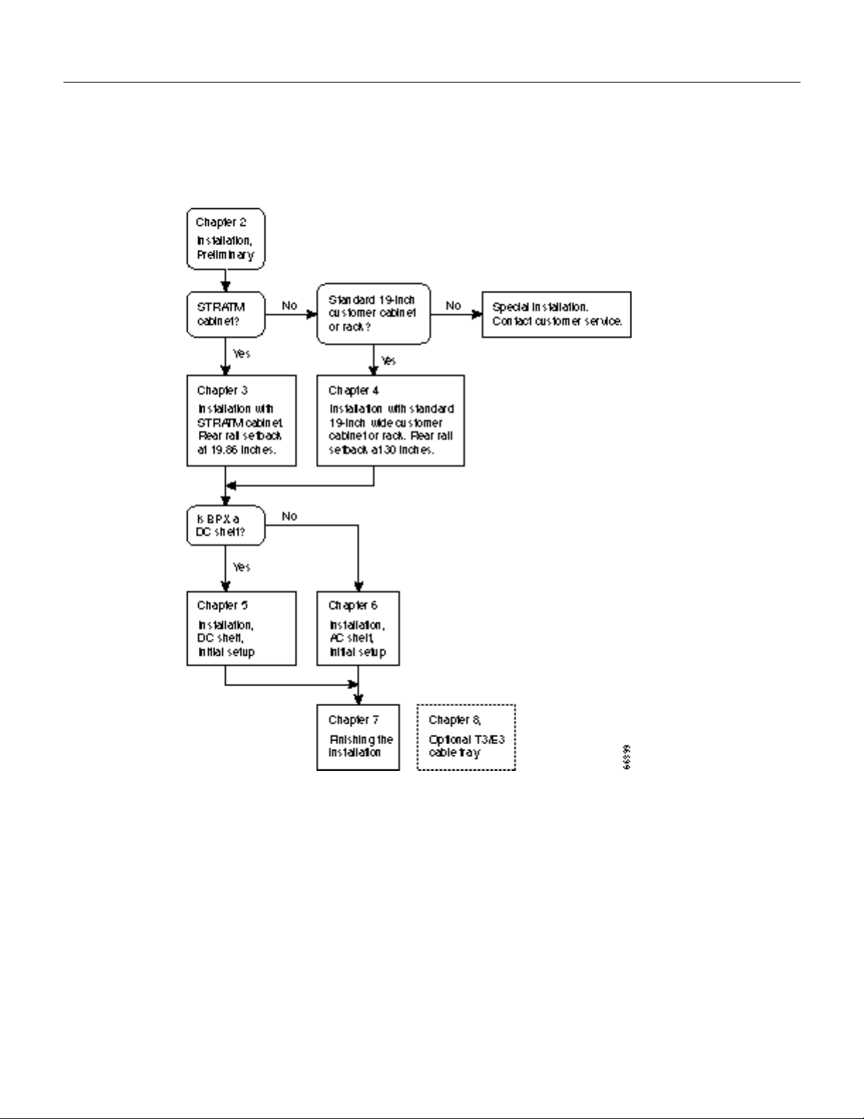
Figure1-1 shows the sequence of operations followed during the installation of the BPX. A
summary of this sequence is as follows:
— Chapter2, Introduction, provides preliminary setup instructions for the mechanical
installation of a BPX shelf. Depending on the type of rack or cabinet, the installer is then
directed to either:
— Chapter3, Installation, with STRATM Cabinet with rear rail setback at 19.86 inches, or
— Chapter4, Installation, with Customer Cabinet that is 19 inches wide with a rear rail setback
of 30 inches.
— Otherwise, the installation is non-standard and requires that Customer Service be contacted.
The BPX shelves are either AC or DC powered. At the completion of the procedures in Chapter3 or
Chapter4, the installer is directed to the appropriate power setup and connection chapter:
— Chapter5, Installation, DC Shelf Initial Setup, or
— Chapter6, Installation, AC Shelf Initial Setup.
The remaining procedures are common and the installer is directed to the final setup and
configuration procedures in:
— Chapter7, Finishing the Installation
An optional cable management tray and optional BXM T3/E3 cable management brackets are
available for use with T3/E3 BXM cards. The brackets are for use with cards set up as non-redundant
(single cables rather than Y-cabling). The tray is designed primarily for use in a mid-mount open rack
configuration. Instructions for installing the optional tray are provided in:
— Chapter8, T3/E3 Cable Management Tray
Introduction1-1
Page 20
Support
Figure1-1 Installation Sequence
Support
Contact Customer Service for more information. In North America, call Customer Support toll free
at 800-553-6387. International customers should contact your local Cisco sales office or call
408-526-400 and ask for Customer Service.
1-2 BPX Service Node Installation, Release 8.5
Page 21

CHAPTER
Installation, Preliminary
This chapter provides preliminary installation steps for the BPX, including the mechanical
installation of the BPX shelf in a STRATM cabinet or vendor supplied standard 19 inch (48.25 cm)
equipment rack.
This chapter contains the following sections:
Site Preparation
Parts Checklist
Safety Requirements
2
Mechanical Installation
WarningInstallation should be performed by authorized personnel only.
Site Preparation
The BPX has the following site preparation requirements.
• Space
Each BPX shelf requires floor space of 22 inches (55.9 cm) wide and 80 inches (203.2 cm) deep
to assure sufficient clearance around the cabinet to allow access to the front and back of the unit.
• Power
An AC or DC power source must be available within 6 feet (2 m.) of the rear of the BPX shelf.
A maximum configuration for an AC powered BPX may require up to 2333 VA (13 A at 180 VAC,
10 A at 230 VAC). A maximum configuration for a DC powered BPX may require up to 1680
Watts (40 A at –42 VDC, 35 A at -48 VDC).
• Cooling
The site must be capable of maintaining an ambient temperature of 40°C maximum
(recommended range 20°C to 30°C) while the system is operating. A fully loaded BPX may
dissipate up to 7200 BTUs. It is extremely important that the BPX is positioned to assure an
unrestricted air flow through the enclosure.
Installation, Preliminary2-1
Page 22

Parts Checklist
Parts Checklist
Before proceeding, go through this parts checklist to verify that all the parts you ordered are present,
and that they are all in good condition. If there is anything missing or damaged, report it to your
Cisco Order Administration representative.
Plug-in cards may be shipped installed or under separate cover. The exact number of cards will vary
from site to site, depending on the selected configuration. The BPX is shipped with all unused slots
covered by backplane inserts which prevent radio frequency emissions from the equipment. The unit
must not be operated with any unused slots left uncovered.
2-2 BPX Service Node Installation, Release 8.5
Page 23

Parts Checklist
Refer to the list below and check the number and type of cards shipped against the number and type
of card you ordered.
If a DC version, the correct number of Power Entry modules.
If an AC version, the unit has the correct number of power supplies (1 or 2).
For non- redundant configuration, one Broadband Controller Card. This can be a
BCC-4, BCC-3, or a BCC-32 depending on system configuration
For a non-redundant configuration, one Broadband Controller backcard. For a
BCC-4 or BCC-3 front card, a BCC-3-bc backcard must be used. For a BCC-32
front card, a BCC-bc backcard must be used.
For a redundant configuration, two Broadband Controller Cards. These can be two
BCC-3s or two BCC-32s.
For a redundant configuration, two Broadband Controller backcards. For BCC-4 or
BCC-3 front cards, these must be BCC-3-bc backcards. For BCC-32 front cards,
these must be BCC-bc backcards.
One ASM card.
One LM-ASM card.
Correct number of BXM cards.
Correct number of BNI cards.
Correct number of ASI cards.
One line module backcard for each BXM, as applicable (e.g., BPX-T3/E3-BC,
MMF-155-4, SMF-155-4, SMFLR-155-4, MMF-155-8, SMF-155-8,
SMFLR-155-8, SMF-622, SMFLR-622, SMF-622-2, or SMFLR-622-2).
One line module backcard (e.g., BPX-T3-BC, BPX-E3-BC, MMF-2-BC,
SMF-2-BC, or SMFLR-2-BC) for each BNI, as applicable.
One line module backcard (e.g., BPX-T3-BC, BPX-E3-BC, MMF-2-BC,
SMF-2-BC, or SMFLR-2-BC) for each ASI, as applicable.
NoteAn inventory of the installed cards is taped to the BPX stating each card's serial number,
All cables specified in the order.
revision number, and slot number (serial and revision numbers are also found on the component side
of each card).
Installation, Preliminary 2-3
Page 24
Safety Requirements
Safety Requirements
The following paragraphs contain safety information for system planners, installers, and
maintenance personnel. The mechanical design of the BPX prevents any access to exposed voltages
without the use of tools. When installed properly, all front and rear cards are held captive
mechanically.
WarningFor protection against shock hazard, verify all power cords or cables are disconnected
before servicing unit (there may be more than one). The highest voltage that may be present in the
node when powered up is 264 VAC (AC systems) or 56 VDC (DC systems).
Laser Safety Guidelines
The optical ports contain an information label as shown in Figure2-1.
Figure2-1 Laser Information Label
Warning
multi-mode products when no fiber cable is connected. Avoid exposure and do not look into open
apertures. (For translated versions of this warning, refer to the Regulatory Compliance and Safety
Information that accompanied your equipment).
WarningClass 1 laser product. (For translated versions of this warning, refer to the Regulatory
Compliance and Safety Information that accompanied your equipment).
WarningLaser radiation when open. (For translated versions of this warning, refer to the
Regulatory Compliance and Safety Information that accompanied your equipment).
Invisible laser radiation may be emitted from the optical ports of the single-mode or
2-4 BPX Service Node Installation, Release 8.5
Page 25

Power and Grounding
Step1 In order for the BPX to function safely and correctly, along with peripheral equipment,
Step2 Certain BPX nodes are supplied with two power feeds (cords). Before commencing
Step3 Ensure that the BPX frame is attached to an isolated ground connection (connection
Step4 A conduit hookup box is factory-installed on each DC Power Entry Module for sites
Step5 For an AC system, verify that the node is powered from a dedicated AC branch circuit.
Safety Requirements
use only the power cords, cables, and connectors specified for the attached peripheral
equipment, and make sure they are in good condition.
installation or maintenance inside the cabinet, be sure both power feeds are disconnected
from their respective sources.
attached directly to ground through an uninterrupted line).
requiring wiring to be enclosed in conduit. A plastic terminal block cover is also provided
for installations that do not require conduit hookup. Install one or the other as protection
for the DC input.
The circuit shall be protected by a dedicated 2-pole circuit breaker sized such that the
rated current and the trip delay is higher and longer than the BPX circuit breaker. A
dedicated 20A, 2-pole AC circuit breaker with a long trip delay is recommended for
installation.
NoteThe BPX uses a 15A (or in newer models a 20_A), 2-pole AC circuit breaker with a medium
trip delay on each AC input. The circuit breaker manufacture is either Carlingswitch (p/n
CA2-B0-34-615-121-C) or Heinemann (p/n AM2-A3-A-0015-02E).
Step6 For a DC system, verify that the node is powered from a dedicated DC branch circuit. The
NoteThe BPX uses a 50A, 1-pole DC circuit breaker with medium trip delay on the -48V input.
The circuit breaker manufacture is Heinemann (p/n AM1S-B3-A-0050-02-H).
Step7 An insulated grounding conductor that is identical in size to the grounded and
CEPT Requirements
All apparatus (e.g., 48 VDC power supplies) connected to the BPX must comply with BS6301 or
EN60950
circuit shall be protected by a dedicated circuit breaker sized such that the rated current
and the trip delay is higher and longer than the BPX circuit breaker. A dedicated 50A,
1-pole DC circuit breaker with a long trip delay is recommended for installation.
ungrounded branch circuit supply conductors, but is green with yellow stripes, is to be
installed as part of the branch circuit that supplies the unit.
EMI Requirements
Compliance with emission regulations depends upon adherence to the installation steps in this
manual, including installation of faceplates for all slots and the use of shielded cables between
systems.
Installation, Preliminary 2-5
Page 26

Mechanical Installation
Mechanical Installation
Weight
A fully loaded, AC-version, BPX node can weigh up to 213 pounds (97 Kgs). A fully-loaded
DC-version BPX may weigh up to 163 pounds (74 Kgs).
Cooling
CautionIf the BPX is to be mounted in an enclosed cabinet, assure that a free flow of air in and out
of the enclosure is provided. Contact Customer Service for further information.
Horizontal Positioning
BPX shelves are designed to be mounted to two sets of vertical mounting rails in either a STRATM
cabinet or a standard 19-inch equipment rack with unrestricted front to rear air flow. When installed
in a STRATM cabinet (Figure2-2), the front flanges of the BPX are secured to the front rails of the
STRATM cabinet. In factory installations, rear support is provided by rear mounting rails in the
cabinet at a setback of 19.86 inches. As an option, a rear set of rails located at a setback of
approximately 30 inches may be used for rear support.
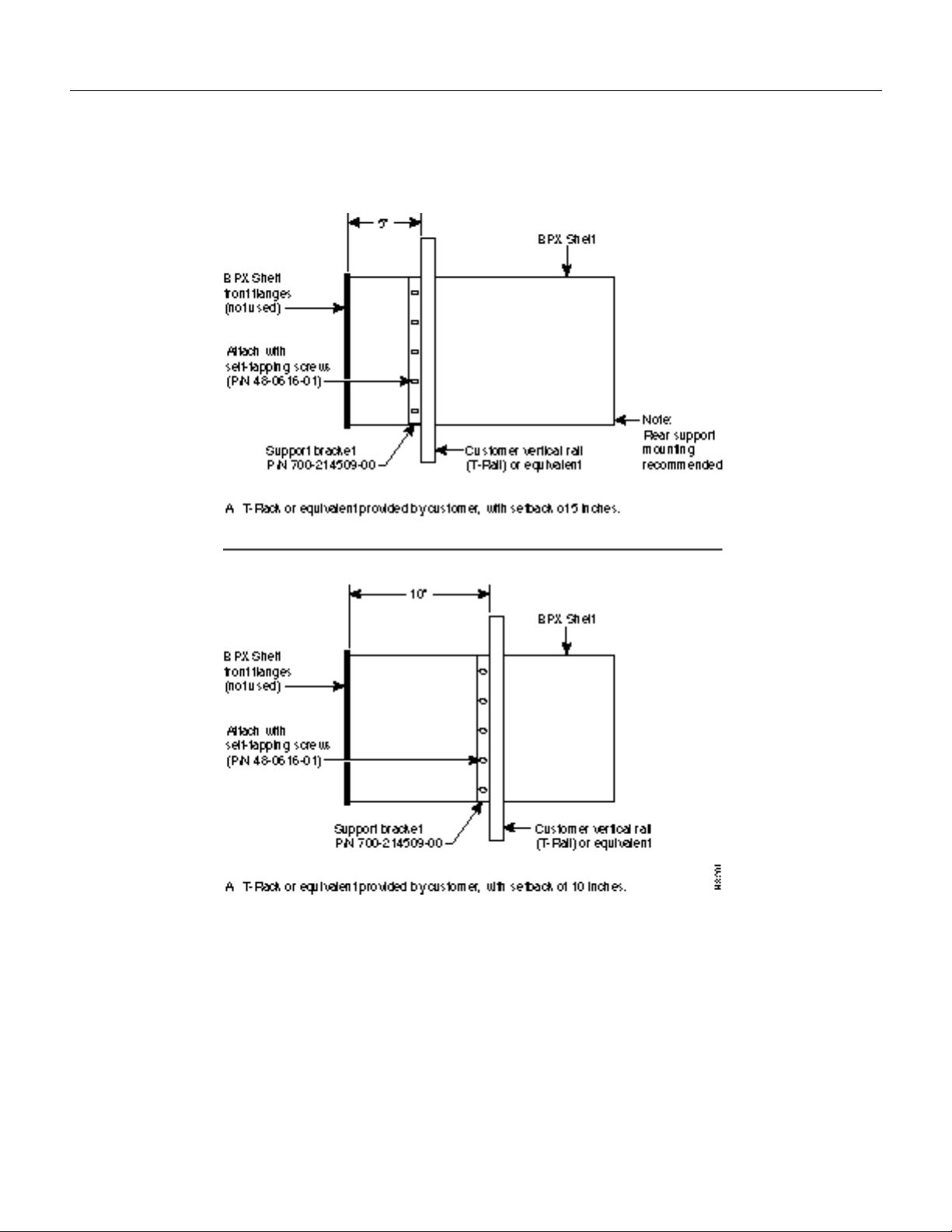
BPX shelves can also be mid-mounted to an open T-Rail type rack (Figure2-3) with unrestricted
front to rear air flow. To facilitate this type of installation, brackets may be fastened to the BPX shelf
at a 5 or 10 inch setback for supporting the front of the BPX shelf. Additional rear mounting support
is also recommended. Contact Customer Service for further information.
Vertical Positioning
For recommended typical equipment configurations in a STRATM cabinet, refer to AppendixA,
STRATM Cabinet Dimensions.
2-6 BPX Service Node Installation, Release 8.5
Page 27
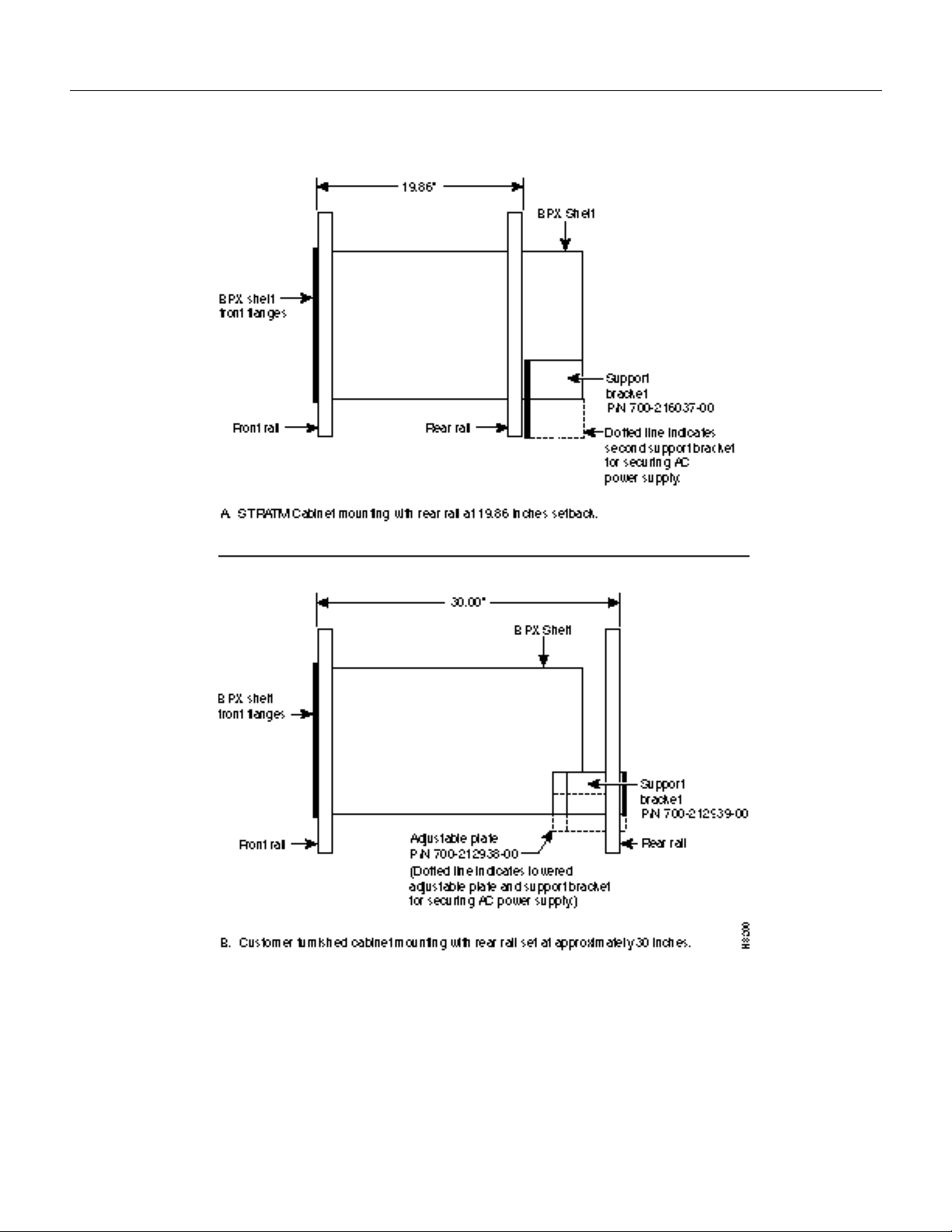
Figure2-2 Cabinet Mounting Options for the BPX Shelf
Mechanical Installation
Installation, Preliminary 2-7
Page 28
Mechanical Installation
Figure2-3 BPX Shelf and T-Rail (Open Rack) or Equivalent Mounting Options
2-8 BPX Service Node Installation, Release 8.5
Page 29

Installing a BPX Shelf, Preliminary Steps
The BPX is designed for mounting in a standard 19-inch (48.25 cm.) equipment rack such as the
standard STRATM cabinet. A minimum width between rails of 17.750 inches (44.45 cm) is required
(Figure2-5 and Figure2-6). Mounting flanges are permanently attached to the front edge of the BPX
shelf. It is recommended that the shelf be mounted with all plug-in cards temporarily removed to
lessen the weight.
There are two types of BPX shelves, AC powered and DC powered. When an AC powered BPX shelf
is installed, an AC Power Supply Tray is installed directly below it. The DC Powered BPX Shelf
contains factory installed DC power entry modules (PEMs) within the shelf itself.
A temporary support bracket and spacer bracket is furnished to ease installation. The pallet tray part
of the shipping container is used in the installation of the BPX. This wooden pallet tray that is
shipped under the BPX chassis is used to lift, align, and support the chassis during installation in a
rack.
The following instructions are for BPX Shelf installation in a STRATM cabinet which has rear rails
at 19.86 inches (50.5 cm) or in a customer supplied standard 19-inch (48.25 cm)_ equipment rack
with rear rails at a 30 inch (76.2 cm) setback.
NoteInstallation in a non-STRATM cabinet or T-Rail type rack is similar to installation in a
STRATM cabinet. Contact Customer Service for recommended rear support details.
Mechanical Installation
To install the BPX in a rack proceed as follows:
Step1 Position the shipping container and pallet in front of the cabinet with the rear of the
chassis towards the cabinet. Remove the foam strips on the sides, front, and rear.
Step2 Remove the card retaining bracket from the front of the chassis by unscrewing the four
Phillips screws. This bracket is used to retain the boards during shipping.
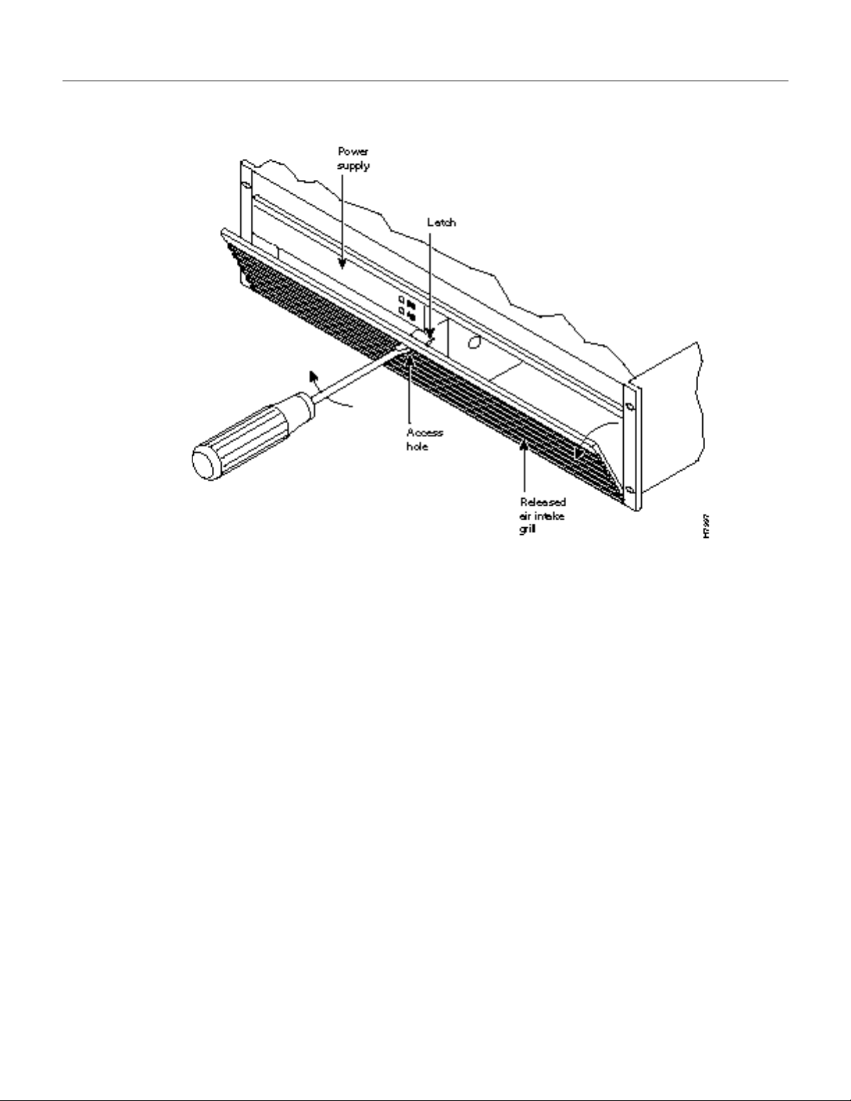
Step3 Remove the Air Intake Grill and all front and rear cards from the shelf and temporarily
set aside as follows:
(a) Locate the small access hole in the top center of the front Air Intake Grille below the
card slots (see Figure2-4 for location).
(b) Insert a small slotted blade screwdriver (0.20/0.25 inch blade width) into the access
hole until it stops (approximately 1 inch).
(c) Carefully rotate the screwdriver approximately a quarter turn in either direction. The
top of the Air Intake Grille should spring out.
(d) Remove Air Intake Grille.
CautionGround yourself before handling BPX cards by placing a wrist strap on your wrist and
clipping the strap lead to the cabinet.
(e) To remove the cards, rotate the extractor handles at the top and bottom of each card
to release the card and slide it out.
Installation, Preliminary 2-9
Page 30
Mechanical Installation
Figure2-4 Removing an Air Intake Grille
Step4
Decide where the BPX is to be located. Refer to Figure2-2 through Figure2-6 for typical
mounting dimensions. Also, for typical mounting configuration examples, refer to
AppendixA, STRATM Cabinet Dimensions. The appendix lists dimensions in inches,
centimeters, and rack mounting units (RMUs). The top of the spacer bracket should be
temporarily installed in the rack 22.75" (57.8 cm.) below the location selected for the top
of the BPX chassis.
Step5 Install the temporary support brackets and spacer bracket (shipped with the unit). Use two
mounting screws to attach each temporary support bracket and two screws to attach the
temporary spacer bracket to the rack (Figure2-7 and Figure2-8).
2-10 BPX Service Node Installation, Release 8.5
Page 31

Figure2-5 Rack Mounting Dimensions, DC Powered Shelf
Mechanical Installation
Installation, Preliminary 2-11
Page 32

Mechanical Installation
Figure2-6 Rack Mounting Dimensions, AC Powered Shelf
2-12 BPX Service Node Installation, Release 8.5
Page 33

Figure2-7 Temporary Spacer Bracket and Support Bracket Installation
Mechanical Installation
Figure2-8 BPX Shelf Aligned with Temporary Support Brackets and Bar
Installation, Preliminary 2-13
Page 34

Mechanical Installation
NoteIt is recommended that all BPX systems use a set of vertical support rails to provide additional
support for the rear of the chassis. In the STRATM cabinet these are located at a 19.86 inch setback
from the front in factory installations.
Step6 If the BPX Shelf is being installed in a STRATM cabinet and is using factory installed
Step7 If the BPX Shelf is being installed in a customer supplied cabinet using rear rail mounting
rear rails located at a 19.86 inch setback from the front, go to Chapter3, Installation, with
STRATM Cabinet.
support brackets located at a setback of approximately 30 inches from the front, go to
Chapter4, Installation, with Customer Cabinet.
2-14 BPX Service Node Installation, Release 8.5
Page 35

CHAPTER
Installation, with STRATM Cabinet
This chapter provides installation steps for the mechanical placement of a BPX shelf in a standard
STRATM cabinet. This cabinet provides rear rails at a 19.86 inch (50.5 cm) setback from the front
of the cabinet.
Before proceeding to this chapter, the procedures should be completed, in:
— Chapter2, Installation, Preliminary
3
Installing a BPX Shelf, Rear-Rail Setback at 19.86 Inch
The steps in this procedure apply to a BPX Shelf that is being installed in a STRATM cabinet and
using factory installed rear rails located at 19.86 inches from the front.
If the BPX shelf is DC-powered, the DC Power Entry Modules are factory-installed in the lower
portion of the rear of the BPX shelf (Figure3-1). Locate the DC Power Entry Module(s) and make
sure it/they are equipped as ordered. If the BPX shelf is AC-powered, an AC Power Tray is installed
below it as part of the installation process.
Installation, with STRATM Cabinet3-1
Page 36

Installing a BPX Shelf, Rear-Rail Setback at 19.86 Inch
Figure3-1 Location of DC Power Entry Module(s), Cabinet Rear View
3-2 BPX Service Node Installation, Release 8.5
Page 37

Preliminary Procedure:
Proceed as follows to install either an AC or DC powered BPX shelf, referring to Figure3-2 and
Figure3-3 and to either Figure3-4 for DC powered systems or Figure3-5 for AC powered systems:
Step1 Locate the two rear support brackets (P/N 700-216037-00) in the miscellaneous parts kit.
Step2 Secure one each support bracket to the back of the rear rail located at 19.86 inches from
NoteEuropean installation may use a size M6 metric screw.
WarningAn empty BPX enclosure weighs 75 pounds (34 Kgs.) and requires a 2 or 3-person lift to
move into place.
Step3 With one person on each side of the BPX shelf, lift the pallet tray and BPX chassis
Installing a BPX Shelf, Rear-Rail Setback at 19.86 Inch
the front flange of the STRATM cabinet using #10-32 machine screws and flat washers.
positioning the slots at the rear of the pallet tray over the locating tabs on the spacer
bracket (Figure3-2).
Step4 Slide the BPX shelf back over the temporary support brackets and into place.
Figure3-2 BPX Shelf Aligned with Temporary Support Brackets and Bar
Step5
Step6 Attach the BPX shelf to the previously installed support brackets by inserting 8 each
Attach the BPX shelf to the cabinet front rail using 8 each # 10-32 screws.
#10-32 machine screws and flat washers from inside the back of the BPX shelf.
Installation, with STRATM Cabinet 3-3
Page 38

Installing a BPX Shelf, Rear-Rail Setback at 19.86 Inch
Step7 Remove the temporary support brackets and spacer bracket.
Step8 If this is a DC powered shelf, proceed to Chapter5, Installation, DC Shelf Initial Setup.
Step9 If this is an AC powered shelf, proceed to Chapter6, Installation, AC Shelf Initial Setup.
3-4 BPX Service Node Installation, Release 8.5
Page 39

Installing a BPX Shelf, Rear-Rail Setback at 19.86 Inch
Figure3-3 BPX Shelf with Rear Rail Mounting at Setback of 19.86 inches
Installation, with STRATM Cabinet 3-5
Page 40

Installing a BPX Shelf, Rear-Rail Setback at 19.86 Inch
Figure3-4 Rear Mounting Brackets, with 19.86 Inch Rear Rail Setback (DC Systems)
Figure3-5 Rear Mounting Brackets, 19.86 Inch Rear Rail Setback (AC-Systems)
3-6 BPX Service Node Installation, Release 8.5
Page 41

Installation, with Customer Cabinet
This chapter provides installation steps for the mechanical placement of a BPX shelf in a standard
19-inch customer supplied equipment cabinet or rack with a rear rail setback at 30 inches.
Before proceeding to this chapter, the procedures should be completed, in:
— Chapter2, Installation, Preliminary
Installing a BPX Shelf, Rear Rail Setback at 30-Inch
The steps in this procedure apply to a BPX shelf that is being installed in a customer supplied cabinet
with rear vertical rails located at a setback of approximately 30 inches from the front.
CHAPTER
4
If the BPX shelf is DC-powered, the DC Power Entry Modules are factory-installed in the lower
portion of the rear of the BPX shelf itself. Locate the DC Power Entry Module(s) and make sure
it/they are equipped as ordered. If the BPX shelf is AC-powered, an AC Power Assembly will be
installed below it.
Figure4-2 shows the location of the rear located third rails in a customer supplied cabinet and of the
corresponding adjustable plates and support brackets on the BPX shelf.
Preliminary Procedure:
Proceed as follows to install the BPX shelf, referring to Figure4-1 through Figure4-3, and to either
Figure4-4 for DC powered systems or Figure4-5 for AC powered systems.
Step1 With one person on each side of the BPX shelf, lift the pallet tray and BPX shelf
Step2 Slide the BPX shelf back over the support brackets and into place.
Step3 Secure the BPX shelf to the front rail using 8 each #10-32 screws.
NoteEuropean installation may use a size M6 metric screw.
Step4 Locate the two rear support brackets and adjustable plates in the miscellaneous parts kit.
positioning the slots at the rear of the pallet tray over the locating tabs on the spacer
bracket (Figure4-1).
Step5 Position the adjustable plates with the tabs in the three punchouts facing up as shown in
Figure4-3.
Installation, with Customer Cabinet4-1
Page 42

Installing a BPX Shelf, Rear Rail Setback at 30-Inch
Figure4-1 BPX Cabinet Aligned with Temporary Support Brackets and Bar
Step6
Align the top and bottom holes in the adjustable plates with corresponding holes in the
side panel of the BPX shelf. (The bottom of the plates should be approximately aligned
with the bottom of a DC powered BPX shelf. They should be extended below the bottom
of an AC powered BPX shelf so that the AC Power Supplies can be secured to the shelf.)
Step7 Secure one each adjustable plate to each side of the BPX shelf using (2) each #10-32
machine screws and flat washers.
Step8 Attach a rear support bracket to each one of the adjustable plates with 2 each 10-32 screws
and washers. Do not tighten yet.
Step9 Secure the support brackets to the rear located vertical rails using 2 each #10-32 screws
(or up to M6 metric screws). You may have to lift the BPX shelf slightly to align the holes
in the bracket to the holes in the rack.
Step10 Tighten the screws attaching the support bracket to the adjustable plate.
Step11 Slide a cable strap over each of the three tabs on the support brackets.
Step12 Remove the temporary support bracket and spacer bracket from the front of the cabinet.
Step13 If this is a DC powered shelf, proceed to Chapter5, Installation, DC Shelf Initial Setup.
Step14 If this is an AC powered shelf, proceed to Chapter6, Installation, AC Shelf Initial Setup.
4-2 BPX Service Node Installation, Release 8.5
Page 43

Installing a BPX Shelf, Rear Rail Setback at 30-Inch
Figure4-2 BPX Shelf with Rear Rail Mounting at Setback of 30 Inches
Figure4-3 Rear Mounting Brackets, Detail
Installation, with Customer Cabinet 4-3
Page 44

Installing a BPX Shelf, Rear Rail Setback at 30-Inch
Figure4-4 Rear Mounting Brackets, with 30 Inch Rear Rail Setback (DC Systems)
Figure4-5 Rear Mounting Brackets, 30 Inch Rear Rail Setback (AC-Powered Systems)
4-4 BPX Service Node Installation, Release 8.5
Page 45

CHAPTER
Installation, DC Shelf Initial Setup
This chapter describes how to make the DC power connections.
Before proceeding to this chapter, the procedures should be completed, in either:
— Chapter3, Installation, with STRATM Cabinet, or
— Chapter4, Installation, with Customer Cabinet.
This chapter contains the following sections:
DC Power Input Connections
5
Card Slot Fuses
Fan Power Fuses
DC Power Input Connections
There are two versions of the DC-powered BPX cabinet as follows:
• Single DC Power Entry Module, single power feed.
• Dual DC Power Entry Module, dual power feed.
For DC systems, the wiring is connected from a 48 VDC power source to one or two DC Power Entry
Modules (Figure5-1). This wiring is provided by the installer. A metallic conduit box that meets all
electrical codes for attaching electrical conduit is factory-installed Figure5-2. A simple plastic cover
is also enclosed for customers who do not require conduit protection for the input power leads
Figure5-3. Use conduit if required by local electrical code.
To make DC power connections to the BPX:
Step1 Locate the conduit terminating box, one for each Power Entry Module. (Figure5-2).
Remove the two cover screws and lift off the cover. If conduit is required, proceed to step
2. If conduit is not required, proceed to step 3.
Step2 Determine which knockout to remove (rear or bottom). Remove knockout and install
conduit fitting.
Step3 If conduit is not required, remove the conduit box by removing the two screws, one above
the terminal block and one below it.
Step4 Run three wires from the DC terminal block to a source of 48 VDC. Use 8 AWG wire
(ormetric equivalent for E1 systems). Use a #10 screw ring lug designed for 8 AWG wire
° lug if using conduit box) to terminate the wires.
(90
Installation, DC Shelf Initial Setup5-1
Page 46

DC Power Input Connections
CautionEnsure that polarity of the DC input wiring is correct! Connections with reversed polarity
may damage the equipment.
WarningRemember that this is a positive ground system. Connect the positive lead to the +RTN
terminal. Connect the negative lead to the –48V terminal. Connect the earth ground to the middle
terminal labeled SAFETY GROUND. See Figure5-1, Figure5-2 and Figure5-3. For personnel
safety, the green/yellow wire must be connected to safety (earth) ground at both the equipment and
at the supply side of the dc wiring.
Figure5-1 DC Power
Step5
Terminate the DC input wiring to a DC source capable of supplying at least 50 amperes.
A 50A dc circuit breaker is required at the 48 VDC facility power source. An easily
accessible disconnect device should be incorporated into the facility wiring. Be sure to
connect the ground wire/conduit to a solid office (earth) ground.
NotePrimary overcurrent protection is provided by the building circuit breaker. In North America,
this breaker should protect against excess currents, short circuits, earth faults in accordance with
NEC/CEC.
Step6 If the system is equipped with dual power feed, repeat steps 1 through 6 for the second
power feed.
Step7 Either replace the cover on the conduit terminating box(es) or attach the plastic cover
plate(s) to the terminal block with screws into the two terminal block standoffs. See
Figure5-2 and Figure5-3.
Step8 Proceed to Chapter7, Finishing the Installation.
5-2 BPX Service Node Installation, Release 8.5
Page 47

Figure5-2 DC Power Connections—With Conduit Box
DC Power Input Connections
Installation, DC Shelf Initial Setup 5-3
Page 48

Card Slot Fuses
Figure5-3 DC Power Connections—Without Conduit Box
Card Slot Fuses
Fuses for each card slot have been added to the backplane of later versions of the BPX to protect
against catastrophic backplane damage in the event of a shorted connector power pin. Backplane
fuses should rarely, if ever, need replacement. The card slot fuses are designated F4 through F18,
corresponding to card slot numbers 1 through 15, respectively.
Refer to the BPX Service Node Reference document, Repair and Replacement chapter, for
instructions on replacement of these fuses, and contact Cisco Customer Service for assistance
regarding their replacement.
CautionFor continued protection against risk of fire, replace only with the same type and rating of
fuse. Fuses should only be replaced after all power to the BPX has been turned off.
Fan Power Fuses
Fan fuses are located on the backplane of the BPX to protect against catastrophic backplane damage
in the event of a shorted fan cable. Backplane fuses should rarely, if ever, need replacement. The
fuses are designated F1 through F3, corresponding to fans 1 through 3.
5-4 BPX Service Node Installation, Release 8.5
Page 49

Fan Power Fuses
CautionRefer to the BPX Service Node Reference document, Repair and Replacement chapter, for
instructions on replacement of these fuses, and contact Cisco Customer Service for assistance
regarding their replacement.
WarningFor continued protection against risk of fire, replace only with the same type and rating
of fuse. Replace fuses only after all power to the BPX has been turned off.
Installation, DC Shelf Initial Setup 5-5
Page 50

Fan Power Fuses
5-6 BPX Service Node Installation, Release 8.5
Page 51

CHAPTER
Installation, AC Shelf Initial Setup
This chapter explains how to install the AC power supply tray, power supplies, and make AC power
connections.
Before proceeding to this chapter, the procedures should be completed, in either:
— Chapter3, Installation, with STRATM Cabinet, or
— Chapter4, Installation, with Customer Cabinet.
This chapter contains the following sections:
6
Installing an AC Power Supply Tray
Installing an AC Power Supply
AC Power Input Connections
Card Slot Fuses
Fan Power Fuses
Installing an AC Power Supply Tray
The AC Power Supply Assembly is shipped separately and must be mounted directly below the BPX
shelf. It consists of a Power Supply Tray and one or two AC power supplies. The power supplies are
shipped separately from the AC Power Supply Tray and are installed after the BPX shelf is mounted
in place.
All AC-powered systems are required to use a set of rear support brackets to provide additional
support for the rear of the Power Supply Tray. To install the AC Power Supply Tray proceed as
follows:
Step1 Use two screws to attach each of two temporary support brackets and a temporary spacer
bar to the rack (Figure6-1 and Figure6-2).
Step2 Locate the small access hole in the top center of the front Air Intake Grille on the Power
Supply Tray (Figure6-3).
Step3 Insert a slotted blade screwdriver (0.20/0.25 inch blade width) into the access hole until
it stops (approximately 1 inch).
Step4 Carefully rotate the screwdriver approximately a quarter turn in either direction. The top
of the Air Intake Grille should spring out.
Step5 Remove the Air Intake Grille.
Installation, AC Shelf Initial Setup6-1
Page 52

Installing an AC Power Supply Tray
Figure6-1 Temporary Spacer Bracket and Support Bracket Installation
6-2 BPX Service Node Installation, Release 8.5
Page 53

Installing an AC Power Supply Tray
Figure6-2 Power Supply Tray aligned with Temporary Support Brackets and Bar
Installation, AC Shelf Initial Setup 6-3
Page 54

Installing an AC Power Supply Tray
Figure6-3 Removing an Air Intake Grille
6-4 BPX Service Node Installation, Release 8.5
Page 55

Installing an AC Power Supply Tray
Step6 Slide the Power Supply Tray in the rack between the BPX shelf and the temporary support
brackets and spacer bar (Figure6-2). If cables are attached, use care to avoid damaging
them.
Step7 Install screws and washers to loosely secure power supply assembly to the front of the
BPX shelf. Align the front flanges of the Power Supply Tray with the flanges on the BPX
shelf and tighten screws. There should be approximately 1/16” clearance between the
BPX shelf and the Power Supply Tray to provide sufficient clearance for inserting power
supplies.
Step8 Secure the Power Supply Tray to the rear support bracket (plate) using one #10-32 screw
and flat washer on each side. Use the lower hole in the brackets. Figure6-4 shows the
setup for a configuration with the vertical rails at a 30 inch setback.
For a configuration with vertical rails at a 19.86 inch rail setback, attach one #10-32 screw
and flat washer to the single bracket on each side. Use the lower hole in the brackets.
Figure6-5 shows the bracket configuration only; the power supply tray position is the
same as shown for in Figure6-4.
Figure6-4 Securing AC Power Supply Tray, 30-Inch Rail Setback
Installation, AC Shelf Initial Setup 6-5
Page 56

Installing an AC Power Supply Tray
Figure6-5 Securing an AC Power Supply Tray, 19.86 inch Rear Rail Setback
Step9 Connect and secure a power supply interconnect cable (Cable A in Figure6-6) between
the primary AC Power Supply and the BPX backplane power connector.
Step10 Connect and secure a second power supply interconnect cable (Cable B in Figure6-6)
between the redundant AC Power Supply and the BPX backplane power connector.
Step11 Remove the temporary support bracket and spacer bracket from the front of the cabinet.
6-6 BPX Service Node Installation, Release 8.5
Page 57

Installing an AC Power Supply Tray
Figure6-6 AC Power Supply Tray with Redundant AC Inputs (view from rear)
Installation, AC Shelf Initial Setup 6-7
Page 58

Installing an AC Power Supply
Installing an AC Power Supply
The AC Power Supply is an assembly consisting of an AC-DC Converter, cooling fan, LED bezel,
and mounting frame. The AC Power Supply is installed and removed as an integral unit. There may
be one or two AC Power Supplies depending on node configuration. They are housed in the Power
Supply Tray.
Proceed as follows to remove and reinstall an AC Power Supply in the Power Supply Tray:
Step1 First install the Power Supply Tray in a rack (see “Installing an AC Power Supply Tray”
section).
Step2 Set the circuit breaker(s) at the rear of the Power Supply Tray to OFF.
Step3 If not already removed, remove the Power Supply Tray front Air Intake Grille. Locate the
small access hole in the top, center of the front Air Intake Grille for the Power Supply
Tray (Figure6-7).
Figure6-7 Removing an Air Intake Grille
Step4
Insert a small slotted blade screwdriver (0.20/0.25 inch blade width) into the access hole
until it stops, approximately 1 inch (2.5 cm).
Step5 Carefully rotate the screwdriver approximately a quarter turn in either direction. The top
of the Air Intake Grille should spring out.
Step6 Loosen the captive screw in the center of the power supply retainer and rotate the hinged
retainer frame down (Figure6-7).
6-8 BPX Service Node Installation, Release 8.5
Page 59

Figure6-8 AC Power Supply Installation
Installing an AC Power Supply
Step7
Align the power supply in the PS-A slots at the bottom of the Power Supply Tray and
gently slide it in part way (Figure6-8).
Step8 Continue to slide the power supply in until it mates with the rear connector.
Step9 When the power supply is completely seated in its connector, the pin plunger on the left
side of the supply will engage with a hole in the tray. If not, push firmly on the front edge
until the power supply assembly seats in the connector.
Step10 Screw the right-hand thumbscrew in finger tight.
Step11 When a second power supply is provided, install it in the PS-B slot in the same manner
after removing the Blank Panel from Slot B.
Step12 Rotate the power supply retainer up and tighten the center captive screw.
Step13 Install the Air Intake Grille. Press on the top center until the latch snaps into place.
Installation, AC Shelf Initial Setup 6-9
Page 60

AC Power Input Connections
AC Power Input Connections
There are three configurations of the AC-powered BPX cabinet as follows:
• Single power supply, single AC power feed.
• Dual power supplies, single AC power feed.
• Dual power supplies, dual AC power feed.
ft. (3 m.) power cord is supplied with each AC Power Supply Assembly. To make AC power
An 8
connections to the BPX:
Step1 Plug the power cord(s) into the applicable IEC connector(s) as shown in Figure6-9 and
tighten the cord retainers. A separate power cord connects to each of one or two IEC
connectors depending on the version of power supply shelf provided.
Step2 Plug the BPX cord into a 220 to 240 VAC, single-phase, wall outlet capable of supplying
15A. The building circuit should be protected with a 20A circuit breaker.
Step3 For the dual power feed version, plug each power cord into receptacles on separate
building circuits to provide protection against a power feed failure. Each building circuit
should be protected with a 20A circuit breaker.
6-10 BPX Service Node Installation, Release 8.5
Page 61

AC Power Input Connections
Figure6-9 AC Power Supply Connections (Dual and Single Versions Shown)
Installation, AC Shelf Initial Setup 6-11
Page 62

AC Power Input Connections
Step4 The ground (green/yellow) wire of the AC power cord provides the safety ground to the
Figure6-10 AC Power
.
Step5 As applicable, provide a convenience AC outlet strip, with at least four outlets, near the
BPX via the grounding prong on the three-prong connectors. Make sure the building AC
receptacle is also properly grounded (Figure6-10).
BPX node to power optional modems, CSU, or DSUs, test equipment, etc. There is no
accessory AC outlet supplied on the BPX. This outlet strip should be connected to a
source of AC voltage normal for the region (e.g., 115 VAC for domestic US use).
Step6 Proceed to Chapter7, Finishing the Installation.
6-12 BPX Service Node Installation, Release 8.5
Page 63

Card Slot Fuses
Fuses for each card slot have been added to the backplane of later versions of the BPX to protect
against catastrophic backplane damage in the event of a shorted connector power pin. Backplane
fuses should rarely, if ever, need replacement. The card slot fuses are designated F4 through F18,
corresponding to card slot numbers 1 through 15, respectively.
Refer to the BPX Service Node Reference document, Repair and Replacement chapter, for
instructions on replacement of these fuses, and contact Customer Service for assistance regarding
their replacement.
CautionFor continued protection against risk of fire, replace only with the same type and rating of
fuse. Fuses should only be replaced after all power to the BPX has been turned off.
Fan Power Fuses
Fan fuses are located on the backplane of the BPX to protect against catastrophic backplane damage
in the event of a shorted fan cable. Backplane fuses should rarely, if ever, need replacement. The
fuses are designated F1 through F3, corresponding to fans 1 through 3.
Card Slot Fuses
CautionRefer to the BPX Service Node Reference document, Repair and Replacement chapter, for
instructions on replacement of these fuses, and contact Customer Service for assistance regarding
their replacement.
CautionFor continued protection against risk of fire, replace only with the same type and rating of
fuse. Replace fuses only after all power to the BPX has been turned off.
Installation, AC Shelf Initial Setup 6-13
Page 64

Fan Power Fuses
6-14 BPX Service Node Installation, Release 8.5
Page 65

CHAPTER
Finishing the Installation
This chapter explains how to install the BPX cards, check for a 9.6 or 19.2 Gbps backplane, connect
line and trunk cables, connect peripherals, connect to a network management station, initial power
up, and initial configuration.
Before proceeding to this chapter, the procedures should be completed, in either:
— Chapter5, Installation, DC Shelf Initial Setup, or
— Chapter6, Installation, AC Shelf Initial Setup.
This chapter contains the following sections:
7
• Installing the BPX Cards
• Verifying 9.6 or 19.2 Gbps Backplane
• Making T3 or E3 Connections
• Making an ASI-155 or BNI-155 Connection
• Making a BXM OC3 or OC12 Connection
• Making a BXM T3/E3 Connection
• Alarm Output Connections
• Attaching Peripherals
• LAN Connection for the Network Management Station
• Connecting a Network Printer to the BPX
• Connecting Modems
• Making External Clock Connections
• Initial Startup of the BPX
• BPX Management
• Initial Node Configuration Summary
• IP Setup and IP Relay Configuration
• Configuring the LAN Port
• Configuring the AXIS for StrataView Plus NMS Operation (example)
• Adding Virtual Trunks
• Provisioning the BPX Service Node
Finishing the Installation7-1
Page 66

Installing the BPX Cards
Installing the BPX Cards
CautionGround yourself before handling BPX cards by placing a wrist strap on your wrist and
clipping the strap lead to the cabinet, or use the wrist strap that is connected to the cabinet.
The card shelf in the BPX has card slots numbered from 1 to 15, as viewed from left to right from
the front of the cabinet. Front and rear views of the BPX card shelf are shown in Figure7-1 and
Figure7-2, respectively. The configuration rules for the BPX are summarized as follows.
• For non-redundant nodes, either a Broadband Controller Card BCC-4, BCC-3, or BCC-32 is used
in front slot number 7.
• For non-redundant nodes, a BCC-3-bc backcard must be used in back slot number 7 with a
BCC-4 or BCC-3 front card, or a BCC-bc (also known as BCC backcard) must be used in back
slot number 7 with a BCC-32 front card.
• For redundant nodes, two Broadband Controller Cards, a pair of BCC-4s, BCC-3s, or BCC-32s
are used in front slot numbers 7 and 8.
• For redundant nodes, BCC-3 bc backcards must be used in back slot numbers 7 and 8 with BCC-4
or BCC-3 front cards, or BCC-c (also known as BCC backcards) backcards must be used in back
slot numbers 7 and 8 with BCC-32 front cards.
NoteIn some cases it may be possible to operate two of the three types of BCCs with their proper
backcards temporarily for maintenance purposes, i.e., replacing a failed controller card. Contact
Customer Service for assistance.
• ASM in front slot number 15.
• LM -ASM in back slot number 15.
• BNI-3T3, BNI-3E3, BNI-155 in any other front slot than 7, 8, or 15.
• LM -3T3, LM-3E3, 2OC3-SMF, 2OC3-MMF in all back slots with a BNI in the corresponding
front slot
• ASI-2T3, ASI-2E3, ASI-155 in any other front slot than 7, 8, or 15.
• LM -2T3, LM-2E3, 2OC3-SMF, 2OC3-MMF in all back slots with an ASI in the front other than
7, 8, or 15.
7-2 BPX Service Node Installation, Release 8.5
Page 67

Figure7-1 BPX Shelf (front view)
Installing the BPX Cards
Figure7-2 BPX Shelf (rear view, DC shelf shown)
Finishing the Installation 7-3
Page 68

Installing the BPX Cards
Installing Front Cards
CautionGround yourself before handling BPX cards by placing a wrist strap on your wrist and
clipping the strap lead to the cabinet, or use the wrist strap that is connected to the cabinet.
CautionBlank Front Card and Rear Face Plates must be used to fill/cover empty card slots to
eliminate Radio Frequency Interference (RFI) and Electromagnetic Interference (EMI) and to ensure
correct air flow through the card cage.
Systems may be shipped with empty shelves, with filler cards or with plug-in cards installed. If filler
cards are installed in each slot, some of them may need to be replaced with functional cards. The
front cards are held captive mechanically by the Air Intake Grille and can not be removed until the
lower Air Intake Grille is released.
CautionDo not attempt to remove a front card from the BPX cabinet until the Air Intake Grille is
released and lowered or the Air Intake Grille and/or card extractors may be damaged.
Proceed as follows to remove/install a front card.
CautionBefore any card is installed, always examine the chassis backplane and card cage guides
for any signs of loose or misplaced EMI gasketing. Examine the backplane connectors for bent or
damaged connection or pre-power pins.
Step1 Turn off all power to the BPX.
NoteWhile it is a good idea to turn off power when initially installing cards, when replacing cards,
on an operating BPX, it is not necessary to turn off power as the cards are hot pluggable replaceable.
Step2 Locate the small access hole in the top center of the front Air Intake Grille below the card
slots (see Figure7-3 for location).
7-4 BPX Service Node Installation, Release 8.5
Page 69

Figure7-3 Removing an Air Intake Grille
Installing the BPX Cards
Step3
Insert a small slotted blade screwdriver (0.20/0.25 inch blade width) into the access hole
until it stops (approximately 1 inch).
Step4 Carefully rotate the screwdriver approximately a quarter turn in either direction. The top
of the Air Intake Grille should spring out.
Step5 Remove Air Intake Grille.
Step6 To remove a card, rotate the extractor handles at the top and bottom of the card to release
the card and slide it out.
Step7 To insert a new card, position the rear card guides over the appropriate slots at the top and
bottom of the card cage.
Step8 Gently slide the card in all the way to the rear of the slot and seat the board by fully seating
both extractor handles. The handles should snap back to a vertical position when seated.
NoteThe card should slide in with slight friction on the adjacent board’s EMI gaskets. Investigate
any binding. Do not use excessive force.
Finishing the Installation 7-5
Page 70

Installing the BPX Cards
Installing Back Cards
CautionGround yourself before handling BPX cards by placing a wrist strap on your wrist and
clipping the strap lead to the cabinet, or use the wrist strap that is connected to the cabinet.
The optical ports contain an information label as shown in Figure7-4.
Figure7-4 Laser Information Label
Warning
Invisible laser radiation may be emitted from the optical ports of the single-mode or
multi-mode products when no fiber cable is connected. Avoid exposure and do not look into open
apertures. (For translated versions of this warning, refer to the Regulatory Compliance and Safety
Information that accompanied your equipment).
WarningClass 1 laser product. (For translated versions of this warning, refer to the Regulatory
Compliance and Safety Information that accompanied your equipment).
WarningLaser radiation when open. (For translated versions of this warning, refer to the
Regulatory Compliance and Safety Information that accompanied your equipment).
Proceed as follows to install back cards:
Step1 Locate the card to remove.
Step2 For existing installations, remove any cable(s) that may be attached and tag them so they
may be replaced in the same location.
Step3 Loosen the captive mounting screws on both top and bottom of the line module faceplate
with a slotted blade screwdriver (Figure7-5)
Step4 Lift the extractor handles at the top and bottom, and slide out the line module.
Step5 To re-insert the line module, locate the corner edges of the card into the appropriate guide
slots at the top and bottom of the card cage. Gently slide the card in all the way to the rear
of the slot and push to seat the card in the connector.
NoteThe card should slide in easily. Investigate any binding. Do not use excessive force.
Step6 Screw in the captive screws.
Step7 Replace any cables that may have been removed in step 2.
7-6 BPX Service Node Installation, Release 8.5
Page 71

Figure7-5 Installing a Back Card
Verifying 9.6 or 19.2 Gbps Backplane
Verifying 9.6 or 19.2 Gbps Backplane
In order to operate the BPX Service Node at 19.2 Gbps the following is required:
• A 19.2 Gbps backplane
• BCC-4 or later controller cards
• One or more BXM cards
• Release 8.4.00 or later switch software
• A backplane NOVRAM that is programmed to identify the backplane as a 19.2 Gbps backplane.
Switch software will not allow node operation at 19.2 Gpbs unless it can read the backplane
NOVRAM to verify that the backplane is a 19.2 Gbps backplane.
The 19.2 backplane can be visually identified by the small white card slot fuses at the bottom rear of
the backplane. These fuses are approximately 1/4 inch high and 1/8 inch wide. The 9.6 Gbps
backplane does not have these fuses. If the BPX Service Node is a late model, then a 19.2 Gbps
backplane is installed. This can be verified by running the dspbpnv command which will display
“Word #2 =0001” if the backplane NOVRAM has been programmed. If anything else is displayed,
you’ll have to visually check the backplane for the fuses.
Finishing the Installation 7-7
Page 72

Verifying 9.6 or 19.2 Gbps Backplane
If the backplane is a 19.2 Gbps backplane, but the backplane NOVRAM has not been set to display
Word #2 =0001, then the cnfbpnw command may be used to program the NOVRAM as follows:
Step1 Enter cnfbpnv, and the response should be:
Are you sure this is a new backplane (y/n).
Step2 Enter y
Step3 Confirm that the change has been made by entering dspbpnv to confirm the response:
Word #2 =0001
NoteIf for some reason the change does not take place, it will be necessary to change the backplane
NOVRAM. Contact customer service.
Step4 Enter switchcc in order for the change to be recognized by the switch software.
If the backplane is not a 19.2 Gbps backplane, then it will be necessary to install a 19.2 Gbps
backplane to obtain 19.2 Gbps operation. Contact Customer Service.
7-8 BPX Service Node Installation, Release 8.5
Page 73

Making T3 or E3 Connections
Each LM-3T3 and LM-3E3 line module (BNI backcard) provides three ports with a BNC connector
each for the XMT trunk output and for the RCV trunk input. Each LM-2T3 and LM-2E3 line module
(ASI backcard) provides two ports with a BNC connector each for the XMT line output.and for the
RCV line input.Make the T3/E3 connections to each port as follows.
Step1 Bring each cable through the opening at the bottom of the cabinet at the back and route
them up the side.
Step2 The BPX has tie-downs inside the cabinet to hold cabling in place. Pull them apart as
applicable, place the routed cable in position, wrap the ties around the cable and remake
the loops by pressing the two sections together.
Step3 Connect the cables to the BNC connectors on the LM-3T3 or LM-3E3 line modules.
Remember, the RCV is an input to the BPX and XMT is an output from the BPX. The
ports are numbered from top to bottom as indicated in Figure7-6.
NoteMaximum distance from a BPX to a DSX3 cross connect point is approximately 450 feet
(150meters).
Making T3 or E3 Connections
Step4 Record which slot and port number are used for each trunk or line. You'll need the
information later when configuring the network.
Step5 If optional Y-cable redundancy is desired, locate a 3-way BNC Y-cable adapter for each
port to be so equipped. As an alternative to the Y-cable, use a BNC “T” and two short
BNC-BNC cables.
Step6 For card redundancy, make sure there are two appropriate line modules equipped in
adjacent slots.
Step7 Connect two legs of the Y-cable to the XMT T3 or E3 connectors on the same port on
each of the two line modules (Figure7-7). Do the same with the two RCV T3 or E3
connectors.
Step8 Connect the third leg of the XMT and RCV Y-cable adapters to the XMT and RCV trunk
cable.
Finishing the Installation 7-9
Page 74

Making T3 or E3 Connections
Figure7-6 Connecting T3 Cables to BPX LM-T3 (BNI T3 backcard)
7-10 BPX Service Node Installation, Release 8.5
Page 75

Figure7-7 Connecting Y-Cable Adapters to a T3 Port
Making T3 or E3 Connections
Finishing the Installation 7-11
Page 76

Making an ASI-155 or BNI-155 Connection
Making an ASI-155 or BNI-155 Connection
Each OC3 line module provides two ports with both a transmit and receiver connector for each port.
The following applies to the 2OC3-SMF and 2OC3-MMF backcards, except that Y-Cabling
redundancy is supported only for the 2OC3-SMF card. Make connections as follows:
Step1 At the back of the cabinet, route each cable up the inside of the cabinet, as applicable.
Step2 The STRATM cabinet has tie-downs inside the cabinet to hold cabling in place. If using
a STRATM cabinet, pull the tie downs apart as applicable, place the routed cable in
position, wrap the ties around the cable and remake the loops by pressing the two sections
together.
Step3 Connect the cables to the applicable connectors on the OC3 line modules. Remember, the
RCV is an input to the BPX and XMT is an output from the BPX. The ports are numbered
from top to bottom as indicated in Figure7-8.
Making a BXM OC3 or OC12 Connection
Each OC3 or OC12 line module provides ports with both a transmit and receiver connector for each
port. The following applies to OC3 and OC12 backcards, except that Y-Cabling redundancy is
supported only for the SMF cards. Make connections as follows:
Step1 At the back of the cabinet, route each cable up the inside of the cabinet, as applicable.
Step2 The STRATM cabinet has tie-downs inside the cabinet to hold cabling in place. If using
a STRATM cabinet, pull the tie downs apart as applicable, place the routed cable in
position, wrap the ties around the cable and remake the loops by pressing the two sections
together.
Step3 Connect the cables to the applicable connectors on the line modules. Remember, the RCV
is an input to the BPX and XMT is an output from the BPX. The ports are numbered from
top to bottom.
Step4 Record which slot and port number are used for each trunk or line. You’ll need the
information later when configuring the network.
Step5 A Y-Cable redundancy connection for the SMF-2-BC backcard is shown in Figure7-8.
Y-Cable redundancy is supported only for the SMF-2-BC backcard which is used with
either the BNI-155 or the ASI-155.
Step6 For card redundancy, make sure there are two appropriate line modules equipped in
adjacent slots.
Step7 Connect two legs of the Y-cable to the XMT connectors on the same port on each of the
two line modules (Figure7-8). Do the same with the two RCV connectors.
7-12 BPX Service Node Installation, Release 8.5
Page 77

Making a BXM OC3 or OC12 Connection
Figure7-8 Connecting Y-Cables to an OC3-SMF Backcard
Finishing the Installation 7-13
Page 78

Making a BXM T3/E3 Connection
Making a BXM T3/E3 Connection
Each T3/E3 line module provides ports with both a transmit and receiver connector for each port.
The backcards can provide 4, 8, or 12 ports. Figure7-9 shows a typical T3/E3 cable connector that
connects to the BXM T3/E3 cards. Y-Cabling redundancy is supported on the BXM T3/E3 cards. An
example of a Y-cable is shown in Figure7-10.
Make connections as follows:
Step1 At the back of the cabinet, route each cable up the inside of the cabinet, as applicable. If
Y-cables are used, the Y-cable connects to the corresponding connectors on adjacent
cards.
Step2 The STRATM cabinet has tie-downs inside the cabinet to hold cabling in place. If using
a STRATM cabinet, pull the tie downs apart as applicable, place the routed cable in
position, wrap the ties around the cable and remake the loops by pressing the two sections
together.
Step3 Connect the cables to the applicable connectors on the T3/E3 line modules. Remember,
the RCV is an input to the BPX and XMT is an output from the BPX. The ports are
numbered from top to bottom.
Step4 For an open rack configuration and where Y-redundancy is not being used, an optional
cable management tray is available to help route cables when a number of DS3/T3 cards
are installed resulting a large number of cables to handle. Refer to Chapter8, T3/E3 Cable
Management Tray
Figure7-9 BXM T3/E3 Cable Connector Detail
7-14 BPX Service Node Installation, Release 8.5
Page 79

Figure7-10 Y-Cable for BXM T3/E3 Cards
Making a BXM T3/E3 Connection
Finishing the Installation 7-15
Page 80

Alarm Output Connections
Alarm Output Connections
Dry contact relay closures are available for forwarding BPX system alarms to a user office alarm
system. Separate visual and audible alarm outputs are available for both major as well as minor alarm
outputs. These outputs are available from a DB15 connector on the LM-ASM faceplate
(Figure7-11). Refer to AppendixB, BPX Cabling Summary, for a list of the pinouts for this
connector. Use switchboard cable for running these connections.
Figure7-11 Alarm Output Connector
7-16 BPX Service Node Installation, Release 8.5
Page 81

Attaching Peripherals
The BPX has two RS-232 serial data ports (labeled CONTROL port and AUXILIARY port) and an
Ethernet port (labeled LAN) on the LM-BCC back card for attaching peripherals.
A network (or each domain in a structured network) must have at least one connection to a control
terminal or StrataView Plus network management workstation. The StrataView Plus NMS
workstation is used to configure and maintain all nodes in a network and report network statistical
data. In addition, a network printer must be connected to the AUXILIARY port if you wish to print.
If it is desired to have Customer Service perform remote troubleshooting, a dial-in modem must be
attached to the network. Procedures for attaching peripherals to the BPX are contained in the
following paragraphs. Be sure to read the manufacturers literature to ensure that you have made the
equipment ready for attachment, before attempting to attach it to the BPX.
Refer to the following for additional information on the following related subjects:
• AppendixB, BPX Cabling Summary, lists the pin assignments for the BPX control terminal port.
• AppendixC, BPX Peripherals, lists the control terminals supported and their required
configuration settings.
• For instructions on using the BPX/IPX commands, see the Command Reference Manual.
• For instructions on using the StrataView Plus workstation, see the StrataView Plus Operations
Guide.
Attaching Peripherals
Connecting a terminal or NMS to the Control Port
A basic VT-100 type terminal may be connected to this port for use in entering commands to bring
up a new node. (Note: Since the StrataView Plus NMS workstation requires a LAN connection to a
node in the network in order to perform its management functions, it is not connected to the Control
Port during normal operation.) In these procedures, the term BCC is used to refer to the BCC-4,
BCC-3 or BCC-32. The BCC-4 and BCC-3 require BCC-3-bc backcards, and the BCC-32 requires
the BCC-bc backcard.
Attach a terminal to the BPX as follows:
Step 1 From the back of the cabinet, run the control terminal RS-232/V.24 cable through the
opening at the bottom and up to the LM-BCC card in back slot 7.
Step 2 For nodes with a single BCC: Locate the CONTROL port connector on the LM-BCC in
slot 7. Attach the RS-232/V.24 cable as shown in Figure7-12, the proceed to Step 5.
Step 3 For nodes with redundant BCCs: A Y-cable is required for this application. Connect one
leg of the Y-cable to the CONTROL port connector on the backcard in slot 7 and the other
leg to the slot 8 CONTROL port connector.
Step 4 Attach a RS-232/V.24 cable to the remaining leg of the Y-cable as shown in
Figure7-13.
Step 5 Fasten the cable connector to the CONTROL port connector with the captive screws on the
connector hood.
Step 6 Plug the control terminal (or StrataView Plus) power cord into the appropriate wall
receptacle (115 VAC or 240 VAC) and switch it on.
Step 7 Set the port function for VT100/StrataView using the cnftermfunc command if connecting
to a StrataView Plus workstation. If using a “dumb” terminal, select VT100 only (# 5).
Step 8 Make sure that the CONTROL port and the terminal or workstation are set to the same baud
rate and check the other communication parameters using the cnfterm command.
Finishing the Installation 7-17
Page 82

Attaching Peripherals
NoteWhen a node is powered up, it enters “boot mode” which has a default speed of 9600 bps. If
the node’s control port has been previously configured to 19,200, the first messages will appear
garbled because the terminal is at 19,200 bps, but the control port (in “boot mode”) is temporarily at
9,600 bps. When the “transition to on-line” occurs, then the speeds will match and the terminal
display will be readable.
Figure7-12 Connections to NMS (Single BCC), LM-BCC Backcard Shown
7-18 BPX Service Node Installation, Release 8.5
Page 83

Attaching Peripherals
Figure7-13 NMS Connections via Control Port (Redundant BCCs), LM-BCCs Shown
Finishing the Installation 7-19
Page 84

LAN Connection for the Network Management Station
LAN Connection for the Network Management Station
The StrataView Plus NMS is connected to an Ethernet port (LAN port) on a node in the network for
the purpose of network management. The LAN port provides the capacity necessary for the network
management traffic and network statistics collection. See Figure7-14 illustrating this connection.
For access to the node using an Internet connection, the Internet Protocol (IP) address, IP subnet
mask, TCP service port, and gateway IP address must be entered by the user with the cnflan
command.
Figure7-14 LAN Connections to BCC Backcards, LM-BCCs Shown
7-20 BPX Service Node Installation, Release 8.5
Page 85

Connecting a Network Printer to the BPX
In most systems, the network printer will be connected to a serial port on the StrataView Plus NMS
terminal server. The maintenance log and all statistics data will reside on the StrataView Plus.
However, it is possible to connect a printer to a node and use various BPX system software print BPX
Peripheralscommands to print locally. This may be helpful during the initial network installation
phase.
AppendixC, BPX Peripherals, lists the types of printers supported by the BPX along with
configuration settings. AppendixB, BPX Cabling Summary lists the pin assignments for the
AUXILIARY port on the BPX and the recommended RS-232/V.24 cable pinout and printer DIP
switch settings. Attach the printer to the BPX as follows:
Step 1 Check the printer RS-232/V.24 cabling pinout, and if required adjust the DIP switches to
the settings indicated for the type of printer to be connected to the BPX.
Step 2 For nodes with single BCC: Connect the RS-232/V.24 printer cable to the AUXILIARY
port on the LM-BCC back card (Figure7-15). Go to Step 4.
Step 3 For nodes with redundant BCCs: A Y-cable is required for this application. Connect one
leg of the Y-cable to the AUXILIARY port connector on the LM-BCC in slot 7 and the other
leg to the AUXILIARY port connector on the LM-BCC in slot 8.
Step 4 Plug the printer power cord into the appropriate AC outlet (115 VAC or 240 VAC).
Connecting a Network Printer to the BPX
Step 5 Set the port function for printer using the cnftermfunc command.
Step 6 Make sure the control port and the printer are set to the same baud rate and check the other
communication parameters using the cnfterm command.
Finishing the Installation 7-21
Page 86

Connecting a Network Printer to the BPX
Figure7-15 Connections to a Network Printer, LM-BCC Shown
7-22 BPX Service Node Installation, Release 8.5
Page 87

Connecting Modems
A modem may be connected to each BPX node to provide remote access by Customer Service
(Figure7-16). For information on connecting and configuring a modem refer to AppendixC, BPX
Peripherals.
Figure7-16 Connecting Modems to the BPX, LM-BCC Shown
Connecting Modems
• An auto-answer modem is used to provide access for remote access. It is connected to the
CONTROL port connector. This port is bi-directional transmit and receive.
Finishing the Installation 7-23
Page 88

Making External Clock Connections
These modems connect to a standard telephone line wall jack. The modem connections require
special cables and setup procedures. Refer to AppendixC, BPX Peripherals, for instructions on
connecting and setting up the modems. If the BPX is equipped with redundant BCCs, an RS-232
Y-cable must be used for these connections.
Making External Clock Connections
The BPX provides connections for supplying a timing signal to synchronize the operation of an
adjacent IPX node. A connector on the BPX LM-BCC back card, labeled EXT CLK OUT supplies
a clock signal at either a T1 or E1 rate which can be connected to the IPX EXTERNAL CLOCKS
connector on the IPX SCC back card (Figure7-17). This uses a straight-through DB15 to DB15
cable, male to male. See AppendixB, BPX Cabling Summary, for pin-outs.
If the BPX node is to be synchronized to some other external equipment or a local digital central
office, one of two other connectors on the LM-BCC can be used to provide a clock input. A DB15
connector labeled EXT CLK IN can be used to connect a balanced T1 or E1 signal, synchronized
from some higher-level source, to the BPX. If an unbalanced 75-ohm E1 signal is available as the
timing source, a BNC EXT CLK IN connector is also provided. The BPX senses an active signal at
any of these inputs and automatically synchronizes to this source rather than the internal Stratum 3
clock source.
NoteContact Customer Service for information on setting up either a 75-ohm or 120 ohm clock
interface on the BCC backcard.
7-24 BPX Service Node Installation, Release 8.5
Page 89

Making External Clock Connections
Figure7-17 Synchronizing a Local IPX to BPX Node, LM-BCCs Shown
Finishing the Installation 7-25
Page 90

Initial Startup of the BPX
Initial Startup of the BPX
Before operating the BPX, check that the following procedures have been performed:
Step 1 The BPX is connected to an appropriate power source with an isolated ground connection,
per the procedures in Chapter5, Installation, DC Shelf Initial Setup, or Chapter6,
Installation, AC Shelf Initial Setup, as applicable.
Step 2 The BPX power cord is plugged into an appropriate power outlet.
Step 3 The full complement of cards for the specific node are mounted in the correct slots,
correctly seated, and locked in place.
Step 4 The T3 or E3 connections are attached to the appropriate LM-3T3/3E3 faceplate.
Step 5 A control terminal (or StrataView Plus Work Station) is connected to the CONTROL port
on the LM-BCC in back slot 7/8, and the terminal's power cord plugged into the appropriate
voltage wall outlet.
Step 6 If needed, a printer may be connected to the AUXILIARY port on the LM-BCC in back slot
7/8 and the printer power cord plugged into the appropriate power outlet.
Step 7 If needed, a modem(s) may be connected to the CONTROL port or AUXILIARY port, as
applicable, on the LM-BCC in back slot 7/8, and the modem(s) power cord(s) plugged into
the appropriate power wall outlet.
Step 8 From the back of the BPX cabinet, turn the power switches to the ON position.
Step 9 From the front of the BPX, observe the cards go through initial diagnostic self-tests.
• The AC power supply(ies) –48V indicator will be on.
• The standby BCCs red “FAIL” light flashes until self-testing and configuration updates
• The remaining cards will show “FAIL” for a few seconds, then become active or
• There may or may not be alarms showing on the BNIs and ASIs. Alarms may be present
BPX Startup Diagnostic
The BPX software provides a group of diagnostic tests to be run on the system's hardware at
power-up. The startup diagnostic either passes or fails the BCC(s) tests. The test result is displayed
on the control terminal screen as pass or fail. Figure7-18 illustrates a successful power-up
diagnostics sequence.
are completed. The other BCC becomes active immediately, but also performs
self-testing and configuration updating. The entire process may take several minutes to
complete.
standby.
on ATM trunk connectors that have not been physically connected to T3 lines.
7-26 BPX Service Node Installation, Release 8.5
Page 91

Figure7-18 Successful Power-Up Diagnostic Screen
Initial Startup of the BPX
If a BCC fails the power-up diagnostic, it will not boot. When that happens, do the following:
NoteOn power-up, the BCC in slot 7 is always the active BCC.
Step 1 Remove the failed BCC from its slot.
Step 2 Reseat the BCC in the same slot.
Step 3 Wait for the power-up diagnostic to run.
Step 4 If the BCC fails the power-up diagnostics a second time, replace it with another BCC that
is known to have passed the test.
Once the software has successfully booted up, the NMS terminal will display the software on-line
screen (Figure7-19). At this point, you may login as a user to the node.
Finishing the Installation 7-27
Page 92

Initial Startup of the BPX
Figure7-19 On-Line Screen
Transition to On-Line
Enter User ID:
7-28 BPX Service Node Installation, Release 8.5
Page 93

BPX Management
You can monitor, manage and troubleshoot the BPX using the StrataView Plus Network
Management Station. Commands are issued to a BPX node through the Node Administration
window. Frame Relay connections are added via the StrataView Plus Connection Manager. You can
display and monitor the network’s topology, monitor alarms, events, and statistics. Refer to the Cisco
StrataCom StrataView Plus Operations Guide for more information.
For detailed configuration information, refer to the Cisco StrataCom Command Reference
publication.
BPX Management
Finishing the Installation 7-29
Page 94

Initial Node Configuration Summary
Initial Node Configuration Summary
Adding Nodes, Adding Trunks, Shelves, etc.
Refer to the applicable reference publications, Cisco StrataCom IPX Reference, Cisco StrataCom
BPX Service Node Reference, Cisco StrataCom IGX Reference, Cisco StrataCom AXIS Reference,
for node installation and operation.
As a minimum, the nodes need to be configured with name (cnfname), date (cnfdate), time
(cnftime), timezone (cnftmzn), and trunks upped (uptrk) and added (addtrk or addshelf), as
applicable. Connections can also be added now or later, after configuring the nodes for operation
with the SV+ NMS manager.
The basic tasks to configure a BPX are as follows:
• Set up the node.
— Configure the node name (cnfname).
— Configure the time zone (cnftmzn).
— Configure date (cnfdate).
— Configure time (cnftime).
— Configure the LAN interface (cnflan).
Configure the auxiliary or terminal ports to support any necessary external devices such as
—
a local printer, an autodial modem, or an external multiplexer attached to the unit (cnfprt,
cnfterm, cnftermfunc).
• Set up the trunks to other routing nodes.Verify the correct cards are in both the local and remote
nodes (dspcds).
— Up the trunk(s) at each node (uptrk).
— Configure any parameters required for the trunk at each node (cnftrk).
— Add the trunk(s) at each node (addtrk).
— Set up Y redundancy if desired (addyred).
• If using an IPX/IGX Interface Shelf, configure it as shelf.
— Up the trunk from the AIT/BTM to the BPX using (uptrk). Shelf trunks for the IPX/IGX
must be upped on both the BPX routing hub and the shelf before the shelf can be joined to
the Routing Network.
— Contact Customer Service to configure the IPX/IGX shelf option.
— At the BPX, add the IPX/IGX as a shelf to the BPX (addshelf).
The following two examples are of the screens displayed when “dspnode” is entered at a BPX and
at one of its IPX shelves, respectively. The “dspnode” screen displayed at the “hubone’ bpx node
shows that it is connected to the “shlf3ipx” node via BNI trunk 3.3. The “dspnode” screen displayed
at the “shlf3ipx” node show that it is connected to the bpx via AIT trunk 8.
7-30 BPX Service Node Installation, Release 8.5
Page 95

Initial Node Configuration Summary
Example of dspnode at node “hubone” BPX15 showing feeder shelves
hubone TN edgar BPX 15 8.5 Nov. 20 1996 08:09 PST
BPX Interface Shelf Information
Trunk Name Type Alarm
1.2 shlf1Axis AXIS OK
1.3 shlf2Axis AXIS OK
3.1 shlf1IPX IPX/AF OK
3.2 shlf2IPX IPX/AF OK
3.3 shlf3IPX IPX/AF OK
4.1 shlf4IPX IPX/AF OK
4.3 shlf5IPX IPX/AF OK
Last Command: dspnode
Example of dspnode at node Shlf3IPX showing connection to “hubone”
shlf3IPX TN edgar IPX 8 8.5 Nov. 20 1995 09:24 PDT
BPX Switching Shelf Information
Trunk Name Type Alarm
8 hubone BPX MAJ
Last Command: dspnode
Next Command:
• Adding the Axis Shelf .
— At the BPX, add the AXIS as a shelf to the BPX (addshelf).
• Set up ATM service lines and ports.
— Activate the line (upln).
— Configure the line (cnfln).
— Activate the ports (upport).
— Configure the ports (cnfport).
• Set up ATM connections.
— Add connections (addcon).
— Configure a connection type (cnfcontyp).
Finishing the Installation 7-31
Page 96

IP Setup and IP Relay Configuration
• Set up ATM to frame relay (ATF) connections.
— Add the connections (addcon).
— Configure connection classes (cnfcls).
— Configure connection groups (addcongrp).
• Set up Interface Shelf Frame Relay Connections in Tiered Networks.
— Refer to the Cisco StrataView Plus Operations Guide.
— Only frame relay connections are supported from the IPX Interface Shelf and these are added
and managed by the SV+ Connection Manager via the SNMP protocol. All connections are
treated as end-to-end.
— Frame relay connections terminated at an AXIS Shelf are added and managed by the SV+
Connection Manager via the SNMP protocol. All connections are treated as end-to-end.
— ATM connections terminated at an AXIS IPX Shelf are added and managed using the
Command Line Interface on the AXIS. All connections are treated as end-to-end.
IP Setup and IP Relay Configuration
In setting up network management for a network, both the SV+ workstation and network nodes need
to be configured. SV+ communicates over a standard physical LAN network to a gateway node or
nodes, but a separate in-band IP relay network is setup for all nodes via a gateway node for SNMP
and TFTP in-band communication over the node trunks.
On IPX, BPX, IGX nodes the following commands are used to configure the nodes for operation
with SV+: cnflan, cnfnwip, cnfstatmast, cnfsnmp. The AXIS is configured with cnfifip and
cnfstatsmgr. The cnflan command is only necessary for nodes or shelves in which the LAN port is
actually connected to a physical Ethernet LAN as shown in Figure7-20.
Figure7-20 SV+ Physical LAN and IP Relay Network
7-32 BPX Service Node Installation, Release 8.5
Page 97

Installing StrataView Plus and Associated Applications
Refer to the Cisco StrataView Plus Operations Guide, Cisco StrataView Plus Installation Guide,
Cisco StrataCom Command Reference, and Cisco StrataCom AXIS Reference publications for
additional information.
Configure StrataView Plus Workstation (example)
Step1 Enter physical IP addresses and physcial LAN node names (with a letter“p”, for example
to differentiate from IP relay name) in /etc/hosts and enter IP relay addresses and actual
node names.
beacon% more /etc/hosts
#
# Sun Host Database
#
# If the NIS is running, this file is only consulted when booting
#
127.0.0.1 localhost
#
204.179.61.121 beacon loghost
IP Setup and IP Relay Configuration
# node physical ethernet LAN addresses
204.179.61.104 nw1bpx1p
204.179.61.71 nw1axi1p
# node ip relay addresses
204.179.55.101 nw1ipx1
204.179.55.102 nw1ipx2
204.179.55.103 nw1ipx3
204.179.55.123 nw1igx1
204.179.55.111 nw1bpx1
204.179.55.105 nw1axi1
If the workstation is connected to the corporate network, add any IP addresses and associated
names of hosts that you may want to connect to your workstation, as the NIS is disabled.
Step2 Enter name of gateway node in config.sv, using physical LAN name.g., nw1bpx1p. Note;
normally, a bpx is used for the gateway node because of its greater processing power.
0|Network1|nw1bpx1p|9600|0|7|6|0|30|1024|8.1|
Step3 Enter IP Relay subnet mask at end of rc.local file:
# route add for SV+
route add net 204.179.55.0 nw1ipx1p 1
NoteThe route add command is for all nodes in the 204.179.55.0 subnetwork. The name
“nw1bpx1p” is the name associated with the physical LAN port on the gateway node, e.g., nw1bpx1.
Finishing the Installation 7-33
Page 98

Configuring the LAN Port
Step4 Contact Customer Service. For the workstation to use /etc/hosts, it must not be able to
access the NIS directory. A work around for “Solaris” is to perform the following:
cd /usr/lib/netsvc/ypbind
mv ypbind ypbind_old
Configuring the LAN Port
NoteConfigure the LAN parameters of the nodes before connecting them to a LAN.
NoteRefer to the StrataView Plus Operations document and the Commands Reference for
additional information.
Step 1 Contact your System Administrator to obtain IP addresses for your workstation and for the
BPX/IPX node you are going to configure.
Step 2 Normally, the System Administrator will provide the IP addresses for the workstation and
node. Refer to the SV+ Operations manual for instructions on configuring the SV+
workstation.
The addresses shown are just examples. Use the addresses obtained from your System
Administrator. (This example is for a workstation named “hedgehog” at address
192.187.207.200. It also assumes that the BPX, IGX, or IPX node LAN port for node
sanfran has been assigned an IP address of 192.187.210.30 and a hostname of sanfran. Your
own host name and addresses will be different.)
192.187.207.200hedgehog
192.187.210.30sanfran
NoteIf an NIS is being used (e.g., corporate network), you will need to contact the System
Administrator.
Note5120 is used for the LAN ports on all BPX/IPX ports.
Step 3 Configure the LAN port on the BPX/IPX node using a dumb terminal or an RS-232
connection via the workstation (using the vt command, as applicable) to enter the
appropriate cnflan parameters.
The cnflan command configures the node’s communication parameters so that the node can
communicate with a StrataView Plus terminal over an Ethernet LAN using the TCP/IP
protocol. The parameters contain address information about the Ethernet TCP/IP network
that is used to connect the StrataView Plus station to an IPX or BPX node. The values used
must conform to those of the network and should be supplied by the Ethernet network
administrator.
7-34 BPX Service Node Installation, Release 8.5
Page 99

Configuring the LAN Port
The cnflan command has the following parameters:
• Active IP Address is the Internet Protocol address of the node used in the TCP/IP
protocol.
• IP Subnet Mask is a 32-bit mask. The default for a Class C LAN network is
255.255.255.0. (Other than C Class masks may be used.)
• IP Service Port is the BPX/IPX LAN port number entered in the /etc/service file on the
workstation. It is 5120 for all BPX/IPX nodes.
• Default Gateway IP Address is the Internet gateway address. This is the gateway that
traffic is routed through if the BPX, IGX, or IPX node and workstation are on different
networks. If they are on the same network, the gateway is not used. The default “none”
is displayed in this case. (Note: If a gateway IP is entered and later you want to remove
it, enter 255.255.255.255 opposite the “IP Subnet Mask” prompt and 192.0.0.0 opposite
the “Default Gateway IP Address” prompt and “none” will again be displayed. (Note:
The node will reset itself if you do this.)
A cnflan screen is shown in Figure7-21 for the LAN setup shown in Figure7-22. An IP
address of 192.187.210.30 has been entered as the active IP address for the node. The IP
Subnet mask is entered as 255.255.255.0 for a Class C LAN network. The TCP service port
is entered as 5120. Since the workstation and node are on different networks in this
example, a gateway address of 192.187.207.1 (the address of the node serving as a gateway
for SV+, in this example), which must be obtained from your System Administrator, has
been entered. If the workstation and node are both on the same network, no gateway address
is needed. The “Maximum LAN Transmit Unit” and “Ethernet Address” parameters are not
configurable by the cnflan command. The “Ethernet Address” is a hardware address that is
different for every node controller card, e.g., BCC.
Figure7-21 Configuring a Node’s Control Port (Gateway Router Example)
beta TN YourID.1 BPX 15 8.5 Mar. 3 1997 02:16 PST
Active IP Address: 192.187.210.30
IP Subnet Mask: 255.255.255.0
IP Service Port: 5120
Default Gateway IP Address: 192.187.207.1
Maximum LAN Transmit Unit: 1500
Ethernet Address: 00.C0.43.00.00.20
Type State
TCP UNAVAIL
UDP READY
Telnet READY
This Command: cnflan
Enter IP Address:
Step 4
Connect the StrataView Plus workstation and the BPX node to a LAN network. The LAN
port on the BPX node provides a DB-15 connector that can be connected to a Y-cable which
in turn is connected to an AUI.
Finishing the Installation 7-35
Page 100

Configuring the LAN Port
Step 5 To test that a LAN connection to the BPX LAN port is okay, for example, for a hostname
Step 6 An IP Relay address needs to be configured for each node. Figure7-23 shows an example
Step 7 Once the workstation and BPX node interface have been set up, SV+ can be started.
Note“Sockets” is the BSD Unix name for connections between processes, typically used in
network communication.
of “sanfran” entered in the config.sv file, you could enter the following at the SV+
workstation:
ping sanfran
of using the cnfnwip command to configure the IP Relay address for a node. Also, at the
workstation, the /etc/hosts table and routing need to be set up for each node in the network.
This is so that network management using SNMP and statistics collection using TFTP via
inband ILMI may be carried out. Also, assuming an isolated network for the nodes, the
workstation must be isolated from the NIS reference pages in order that the SV+
workstation consults the /etc/hosts table. Refer to the StrataView Plus Installation and
Operation manuals for further information.
Figure7-24 shows the dsplan screen after SV+ has been started and the communication
sockets are active.
Figure7-22 SV+ LAN Connection via Gateway Router to a BPX Node
7-36 BPX Service Node Installation, Release 8.5
 Loading...