

Page 1

Cisco StrataCom
BPX Reference
Release 8.4
August 2002
Corporate Headquarters
Cisco Systems, Inc.
170 West Tasman Drive
San Jose, CA 95134-1706
USA
World Wide Web URL:
http://www.cisco.com
Tel:
408 526-4000
800 553-NETS (6387)
Fax:
408 526-4100
Customer Order Number: DOC-SCBPXRG-8.4=
Text Part Number: 78-4300-02
Page 2

THE SPECIFICATIONS AND INFORMATION REGARDING THE PRODUCTS IN THIS MANUAL ARE SUBJECT TO CHANGE WITHOUT
NOTICE. ALL STATEMENTS, INFORMATION, AND RECOMMENDATIONS IN THIS MANUAL ARE BELIEVED TO BE ACCURATE BUT ARE
PRESENTED WITHOUT WARRANTY OF ANY KIND, EXPRESS OR IMPLIED. USERS MUST TAKE FULL RESPONSIBILITY FOR THEIR
APPLICATION OF ANY PRODUCTS.
THE SOFTWARE LICENSE AND LIMITED WARRANTY FOR THE ACCOMPANYING PRODUCT ARE SET FORTH IN THE INFORMATION
PACKET THAT SHIPPED WITH THE PRODUCT AND ARE INCORPORATED HEREIN BY THIS REFERENCE. IF YOU ARE UNABLE TO
LOCATE THE SOFTWARE LICENSE OR LIMITED WARRANTY, CONTACT YOUR CISCO REPRESENTATIVE FOR A COPY.
The following information is for FCC compliance of Class A devices: This equipment has been tested and found to comply with the limits for a Class A
digital device, pursuant to part 15 of the FCC rules. These limits are designed to provide reasonable protection against harmful interference when the
equipment is operated in a commercial environment. This equipment generates, uses, and can radiate radio-frequency energy and, if not installed and used
in accordance with the instruction manual, may cause harmful interference to radio communications. Operation of this equipment in a residential area is
likely to cause harmful interference, in which case users will be required to correct the interference at their own expense.
The following information is for FCC compliance of Class B devices: The equipment described in this manual generates and may radiate radio-frequency
energy. If it is not installed in accordance with Cisco’s installation instructions, it may cause interference with radio and television reception. This equipment
has been tested and found to comply with the limits for a Class B digital device in accordance with the specifications in part 15 of the FCC rules. These
specifications are designed to provide reasonable protection against such interference in a residential installation. However, there is no guarantee that
interference will not occur in a particular installation.
You can determine whether your equipment is causing interference by turning it off. If the interference stops, it was probably caused by the Cisco equipment
or one of its peripheral devices. If the equipment causes interference to radio or television reception, try to correct the interference by using one or more of
the following measures:
• Turn the television or radio antenna until the interference stops.
• Move the equipment to one side or the other of the television or radio.
• Move the equipment farther away from the television or radio.
• Plug the equipment into an outlet that is on a different circuit from the television or radio. (That is, make certain the equipment and the television or radio
are on circuits controlled by different circuit breakers or fuses.)
Modifications to this product not authorized by Cisco Systems, Inc. could void the FCC approval and negate your authority to operate the product.
The following third-party software may be included with your product and will be subject to the software license agreement:
CiscoWorks software and documentation are based in part on HP OpenView under license from the Hewlett-Packard Company. HP OpenView is a
trademark of the Hewlett-Packard Company. Copyright © 1992, 1993 Hewlett-Packard Company.
The Cisco implementation of TCP header compression is an adaptation of a program developed by the University of California, Berkeley (UCB) as part of
UCB’s public domain version of the UNIX operating system. All rights reserved. Copyright © 1981, Regents of the University of California.
Network Time Protocol (NTP). Copyright © 1992, David L. Mills. The University of Delaware makes no representations about the suitability of this
software for any purpose.
Point-to-Point Protocol. Copyright © 1989, Carnegie-Mellon University. All rights reserved. The name of the University may not be used to endorse or
promote products derived from this software without specific prior written permission.
The Cisco implementation of TN3270 is an adaptation of the TN3270, curses, and termcap programs developed by the University of California, Berkeley
(UCB) as part of UC B’s pu blic domain v ersio n of th e UNIX operating sy stem. All rights reserved. Copy right © 1981 -1988, Regen ts of the University of
California.
Cisco incorporates Fastmac and TrueView software and the RingRunner chip in som e Token Ring products. Fastmac software is licensed to Cisc o by Madge
Networks Limited, and the RingRunner chip is licensed to Cisco by Madge NV. Fastmac, RingRunner, and TrueView are trademarks and in some
jurisdictions registered trademarks of Madge Networks Limited. Copyright © 1995, Madge Networks Limited. All rights reserved.
XRemote is a trademark of Network Computing Devices, Inc. Copyright © 1989, Network Computing Devices, Inc., Mountain View, California. NCD
makes no representations about the suitability of this software for any purpose.
The X Window System is a trademark of the X Consortium, Cambridge, Massachusetts. All rights reserved.
NOTWITHSTANDING ANY OTHER WARRANTY HEREIN, ALL DOCUMENT FILES AND SOFTWARE OF THESE SUPPLIERS ARE
PROVIDED “AS IS” WITH ALL FAULTS. CISCO AND THE ABOVE-NAMED SUPPLIERS DISCLAIM ALL WARRANTIES, EXPRESSED OR
IMPLIED, INCLUDING, WITHOUT LIMITATION, THOSE OF MERCHANTABILITY, FITNESS FOR A PARTICULAR PURPOSE AND
NONINFRINGEMENT OR ARISING FROM A COURSE OF DEALING, USAGE, OR TRADE PRACTICE.
Page 3

IN NO EVENT SHALL CISCO OR ITS SUPPLIERS BE LIABLE FOR ANY INDIRECT, SPECIAL, CONSEQUENTIAL, OR INCIDENTAL
DAMAGES, INCLUDING, WITHOUT LIMITATION, LOST PROFITS OR LOSS OR DAMAGE TO DATA ARISING OUT OF THE USE OR
INABILITY TO USE THIS MANUAL, EVEN IF CISCO OR ITS SUPPLIERS HAVE BEEN ADVISED OF THE POS SIBILITY OF SUCH DAMAGES.
AtmDirector, AutoConnect, AutoRoute, AXIS, BPX, Cataly st, CD-PAC, CiscoAdvantage, Cis coFusion, Cisco IOS, the Cisco IOS lo go, CiscoLink,
CiscoPro, the CiscoPro logo, CiscoRemote, the CiscoRemote log o, Cis coSecu re, Cis co Sys tems, CiscoV iew, C iscoVi sion, CiscoW orks, ClickStart,
ControlStream, EdgeConnect, EtherChannel, FairShare, FastCell, FastForward, FastManager, Fas tMate, FastPADlmp, FastPADmicro, FastPADmp,
FragmentFree, FrameClass, Fulcrum INS, IGX, Impact, Internet Junction, JumpStart, LAN
2
LAN Enterpris e, LAN2LAN Remote Office, LightSwitch,
MICA, NetBeyond, NetFlow, Newport Systems Solutions, Packet, PIX, Point and Click Internetworking, RouteStream, Secure/IP, SMARTnet,
StrataSphere, StrataSphere BILLder, StrataSphere Connection Manager, StrataSphere Modeler, StrataSphere Optimizer, Stratm, StrataView Plus,
StreamView, SwitchProbe, SwitchVision, SwitchWare, SynchroniCD, The Cell, The FastPacket Company, TokenSwitch, TrafficDirector, Virtual
EtherSwitch, VirtualStream, VlanDirector, Web Clusters, WNIC, Workgroup Director, Workgroup Stack, and XCI are trademarks; Access by Cisco,
Bringing the Power of Internetworking to Everyone, Enter the Net with MultiNet, and The Network Works. No Excuses. are service marks; and Cisco,
the Cisco Systems logo, CollisionFree, Combinet, EtherSwitch, FastHub, FastLink, FastNIC, FastPacket, FastPAD, FastSwitch, ForeSight, Grand,
Grand Junction, Grand Junction Networks, the Grand Junction Networks logo, HSSI, IGRP, IPX, Kalpana, the Kalpana logo, LightStream, MultiNet,
MultiWare, OptiClass, Personal Ethernet, Phase/IP, RPS, StrataCom, TGV, the TGV logo, and UniverCD are registered trademarks of C isco Systems, In c.
All other trademarks, service marks, registered trademarks, or registered service marks mentioned in this document are the property of their respective
owners.
Cisco StrataCom BPX Reference
Copyright © 1997, Cisco Systems, Inc.
All rights reserved. Printed in USA.
Page 4

Page 5

About this Publication xxvii
Objectives xxvii
Audience xxvii
Organization xxvii
Related Documentation xxix
Conventions xxix
Obtaining Documentation xxx
World Wide Web xxx
Documentation CD-ROM xxx
Ordering Documentation xxxi
Documentation Feedback xxxi
Obtaining Technical Assistance xxxi
Cisco.com xxxi
Technical Assistance Center xxxii
Cisco TAC Web Site xxxii
Cisco TAC Escalation Center xxxii
TABLE OF CONTENTS
Chapter 1 Introduction 1-1
General Description 1-1
BPX Capabilities 1-1
Extended Services Processor 1-2
Access Devices 1-2
New with Release 8.4 1-3
Continuing Features with Release 8.4 1-4
StrataSphere Network Management 1-4
Networking 1-4
BPX 1-4
AXIS 1-5
BPX Operation 1-5
The BPX Service Node with AXIS Shelves 1-5
The BPX Service Node with Extended Services Processor 1-5
BPX Switching 1-6
Frame Relay to ATM Interworking 1-6
Network Interworking 1-6
Service Interworking 1-7
Additional Information 1-8
Tiered Networks 1-8
IMA (Inverse Multiplexing ATM) 1-9
Virtual Trunking 1-10
Traffic and Congestion Management 1-11
FairShare1−11
OptiClass1−12
AutoRoute 1-12
Private Network to Network Interface 1-12
Congestion Management, VS/VD 1-12
Table of Contents v
Page 6

Congestion Management, ForeSight 1-13
Network Management 1-14
Network Interfaces 1-14
Service Interfaces 1-15
Statistical Alarms and Network Statistics 1-15
Node Synchronization 1-15
Node Availability 1-16
Node Redundancy 1-16
Node Alarms 1-16
Chapter 2 General Description 2-1
Physical Description 2-1
BPX Enclosure 2-1
Node Cooling 2-3
Node DC Powering 2-3
Optional AC Power Supply Assembly 2-4
Card Shelf Configuration 2-5
Functional Description 2-7
ATM 2-7
Physical Layer 2-7
ATM Layer 2-7
IPX and IGX Trunk Interfaces to ATM 2-13
BPX Addressing Mode 2-13
Simple Addressing Mode 2-13
Cloud Addressing Mode 2-13
FastPacket Adaptation to ATM 2-14
BPX Major Groups 2-16
Chapter 3 BPX Common Core 3-1
BPX Common Core Group 3-1
Broadband Controller Card (BCC-32, BCC-3, BCC-4) 3-2
Features 3-3
Functional Description 3-4
Front Panel Description 3-6
19.2Gbps Operation with the BCC-4 3-8
Back Cards for the BCC-3 and BCC-32 3-8
Alarm/Status Monitor Card 3-12
Features 3-12
Functional Description 3-12
Front Panel Description 3-12
Line Module for the Alarm/Status Monitor Card 3-15
BPX StrataBus 9.6 and 19.2 Gbps Backplanes 3-17
Chapter 4 Network Interface (Trunk) Cards 4-1
BPX Network Interface Group 4-1
BXM Cards, Trunk Mode Summary 4-1
vi Cisco StrataCom BPX Reference
Page 7

Broadband Network Interface Cards (BNI-T3 and BNI-E3) 4-2
Features 4-3
Functional Description 4-3
Egress 4-3
Ingress 4-4
Bandwidth Control 4-5
Loopbacks and Diagnostics 4-6
Front Panel Indicators 4-6
T3 and E3 Line Modules (LM-3T3 and LM-3E3) 4-8
Broadband Network Interface Cards, BNI-155 4-11
Features 4-11
Overview 4-11
Functional Description 4-12
Front Panel Indicators 4-13
OC3, Line Modules (SMF, SMFLR, and MMF) 4-16
Y-Cabling of BNI Backcard, SMF-2-BC 4-19
Chapter 5 Service Interface (Line) Cards 5-1
BPX Service Interface Group Summary 5-1
BXM Cards, Port (UNI) Mode 5-1
ASI-1, ATM Service Interface Card 5-2
Features 5-3
Functional Description 5-3
Configuring Connections (ATM over ASI Example) 5-4
Monitoring Statistics 5-5
Front Panel Description 5-5
LM-2T3 Module 5-8
LM-2E3 Module 5-10
ASI-155, ATM Service Interface Card 5-12
Features 5-12
Overview 5-12
Configuring Connections 5-13
Functional Description 5-13
Monitoring Statistics 5-14
Front Panel Indicators 5-14
ASI-155 Line Module, LM-2OC3-SMF 5-17
ASI-155 Line Module, LM-2OC3-SMFLR 5-17
ASI-155 Line Module, 2OC3-MMF 5-17
Y-Cabling of ASI Backcard, SMF-2-BC 5-17
BXM Cards, Access (UNI) Mode 5-17
Optional Peripherals 5-17
Table of Contents vii
Page 8

Chapter 6 BXM T3/E3, 155, and 622 6-1
BXM Cards 6-1
BXM Capabilities 6-4
Features 6-4
ATM Layer 6-5
Service Types 6-5
Card Operation 6-7
BXM Front Card Indicators 6-7
BXM, Backcard Connectors 6-11
Y-Cabling of SMF-622 Series Backcards 6-15
BXM Functional Description 6-16
Overview, Port (UNI) Mode 6-16
Ingress 6-16
Egress 6-18
Overview, Trunk Mode 6-19
Ingress 6-19
Egress 6-20
Detailed Description, Port (UNI) and Trunk Modes 6-21
DRSIU 6-21
SONET/SDH UNI (SUNI) 6-21
DeMux/Mux 6-21
RCMP 6-21
SABRE 6-21
Ingress and Egress Queue Engines 6-22
SIMBA 6-22
ACP Subsystem Processor 6-22
Fault Management and Statistics 6-23
Fault Management and Statistics, Port (UNI) Mode 6-23
Fault Management and Statistics, Trunk Mode 6-24
Technical Specifications 6-25
Physical Layer 6-25
General Information 6-25
General SONET Notes 6-26
User Commands 6-27
Connection Provisioning 6-27
Diagnostics 6-27
Test 6-27
Statistics 6-27
Configuring Connections 6-28
Configuration Management 6-29
Command Line Interface Examples 6-30
Configuring the BPX for SVCs 6-39
Configuring the AXIS 6-39
Resource Partitioning 6-40
viii Cisco StrataCom BPX Reference
Page 9

BPX ASI SVC Resource Partitioning 6-40
BPX BXM SVC Resource Partitioning 6-42
NNI Trunk SVC Resource Partitioning 6-44
BNI Trunk SVC Resource Partitioning 6-45
BXM Trunk SVC Resource Partitioning 6-46
Chapter 7 ATM Connections 7-1
ATM Connection Services 7-1
SVCs 7-2
Traffic Management Overview 7-3
ABR, Standard ATM Traffic Mgt 4.0 7-4
Standard ABR notes: 7-4
VSVD Description 7-4
BXM Connections 7-4
ForeSight Congestion Control 7-5
ATM Connection Requirements 7-5
Connection Routing 7-6
Addcon Command Syntax 7-6
ATM Connection Configuration 7-7
CBR Connections 7-13
VBR and ATFR Connections 7-14
VBR Connections 7-14
7-15
ATFR Connections 7-15
Release 8.4 ABR Notes 7-17
ABR and ATFST Connections 7-17
ABR Connections 7-17
ATFST Connections 7-20
UBR Connections 7-22
LMI and ILMI Parameters 7-23
Chapter 8 Configuration and Management 8-1
Initial Setup 8-1
Adding Virtual Trunks 8-3
BPX Management 8-5
IP, IP Relay Configuration (Preliminary) 8-5
Installing SV+ and Associated Applications 8-5
Configure SV+ Workstation (example) 8-5
Network Node Configuration (Preliminary) 8-6
Adding nodes, adding trunks, shelves, etc. 8-6
Configuring the IPX, IGX, and BPX for SV+ NMS Operation 8-7
Configuring the AXIS for SV+ NMS Operation (example) 8-8
Resource Partitioning and SVC Configuration 8-9
Table of Contents ix
Page 10

Chapter 9 Repair and Replacement 9-1
Preventive Maintenance 9-1
Troubleshooting the BPX 9-1
General Troubleshooting Procedures 9-2
Displaying the Status of Cards in the Node 9-4
Replacing Parts 9-5
Replacing a Front Card 9-5
Replacing a Line Module (Back Card) 9-7
Replacing a DC Power Entry Module 9-9
Replacing an AC Power Supply 9-11
Field-Installing a Second AC Power Supply 9-12
Replacing the Fan Assembly 9-13
Replacing the Temperature Sensing Unit 9-14
Replacing Card Slot and Fan Fuses on the System Backplane 9-14
Chapter 10 Frame Relay to ATM Network
and Service Interworking 10-1
Service Interworking 10-3
Networking Interworking 10-4
ATM Protocol Stack 10-7
AIT/BTM Interworking and the ATM Protocol Stack 10-8
AIT/BTM Control Mapping, Frames and Cells 10-10
Management, OAM Cells 10-11
Functional Description 10-11
ATF Summary 10-11
Features 10-11
Limitations 10-11
Some ATF Connection Criteria 10-12
Connection Management 10-12
Port Management 10-12
Structure 10-13
Channel Statistics 10-13
OAM Cell Support 10-14
Diagnostics 10-14
User Commands 10-15
Virtual Circuit Features 10-15
User Commands 10-16
AUser Commands 10-16
Management 10-16
Connection Management 10-16
Routing 10-17
Bandwidth Management 10-17
User Interface 10-17
Port Management 10-17
Connection Management 10-18
Signaling 10-18
x Cisco StrataCom BPX Reference
Page 11

Alarms 10-18
Chapter 11 Tiered Networks 11-1
Introduction 11-1
Tiered Network Implementation 11-2
General 11-3
Definitions 11-3
SW and HW Requirements 11-3
Upgrades 11-4
Co-locating Routing Hubs and Shelves 11-4
Network Management 11-4
ForeSight 11-5
Preferred Routing 11-5
Local and Remote Loopbacks 11-5
Testcon and Testdly 11-5
IPX Shelf Description 11-5
Configuration and Management 11-6
Shelf Management 11-6
Alarm Management of Interface Shelf on the BPX Hub Node 11-7
Alarm Management on the IPX Shelf 11-7
Port Management 11-7
Connection Management 11-7
Bandwidth Management 11-7
Statistics 11-7
Diagnostics 11-7
SV+ Interface 11-8
Chapter 12 BPX SNMP Agent 12-1
Introduction 12-1
SNMP Overview 12-1
SNMP Functions 12-3
Responses to Get (Get-Next) Requests 12-4
ATM Set Requests 12-4
Responses to Set Requests 12-5
MIB II Support 12-5
StrataCom Proprietary MIB Structure 12-6
Switch Service Objects 12-6
Switch Connections 12-6
Bandwidth Class 12-7
Endpoint Statistics 12-7
Endpoint Mapping 12-7
Appendix A BPX Node Specifications A-1
General A-1
Table of Contents xi
Page 12

ATM Trunk Interface (BXM-T3/E3 Cards) A-3
ATM Trunk Interface (BXM-155 Cards) A-4
ATM Trunk Interface (BXM-622 Cards) A-5
ATM T3 Trunk Interface (BNI-T3, LM-3T3) A-6
ATM E3 Trunk Interface (BNI-E3, LM-3E3) A-7
ATM OC3 Trunk Interface (BNI-OC3, LM-OC3) A-8
ATM Service Interface (BXM-T3/E3 Cards) A-9
ATM Service Interface (BXM-155 Cards) A-9
ATM Service Interface (BXM-622 Cards) A-9
ATM Service Interface (ASI-1, LM-2T3) A-10
ATM Service Interface (ASI-1, LM-2E3) A-10
ATM Service Interface (ASI-2, LM-OC3) A-11
Appendix B BPX Cabling Summary B-1
Trunk Cabling B-1
Power Cabling B-1
AC Powered Nodes B-1
DC Powered Nodes B-2
LM-BCC Cabling B-2
Auxiliary and Control Port Cabling B-2
LAN Port Cabling B-3
Modem Cabling B-3
External Clock Input Cabling B-4
T1 Clock Cabling B-4
E1 Clock Cabling B-5
External Alarm Cabling B-6
Standard BPX Cables B-6
Redundancy “Y” Cable B-7
Appendix C BPX Peripherals Specifications C-1
Network Management C-1
StrataView Plus Terminal C-1
Control Port, Local Control C-1
Printer C-2
DIP Switch Settings for Okidata 184 C-2
Modems, Dial-In and Dial-Out C-4
Motorola V.34R BPX Dial-In Configuration C-4
BPX Auto-Answer (Dial-In to BPX) C-4
IPX Auto-Dial to Customer Service C-6
Appendix D AT3-6ME Interface Adapter D-1
xii Cisco StrataCom BPX Reference
Page 13

Application D-1
General Description D-1
Equipment Description D-2
Interface Connectors D-2
Front Panel Indicators D-3
DIP Switches D-4
Installation D-6
System Connections D-6
AT3-6ME Configuration D-6
BPX or IPX Port Configuration D-7
Operation D-7
Power-Up Sequence D-8
Normal Operation D-8
Remote Loop Operation D-8
Terminal Operation D-9
Commands D-9
Specifications D-10
T3 interface D-10
T2 Interface D-11
Power D-11
Mechanical D-11
Terminal Interface D-11
Appendix E Glossary E-1
Index
Table of Contents xiii
Page 14

xiv Cisco StrataCom BPX Reference
Page 15

Table of Contents xv
Page 16

xvi Cisco StrataCom BPX Reference
Page 17

Table of Contents xvii
Page 18

xviii Cisco StrataCom BPX Reference
Page 19

LIST OF FIGURES
Figure 1-1 BPX General Configuration Example 1-2
Figure 1-2 Frame Relay to ATM Network Interworking 1-7
Figure 1-3 Frame Relay to ATM Service Interworking 1-8
Figure 1-4 Tiered Network 1-9
Figure 1-5 Virtual Trunking Example 1-10
Figure 2-1 BPX Cabinet Exterior Front View 2-2
Figure 2-2 BPX Cabinet Exterior Rear View 2-3
Figure 2-3 DC Power Entry Module Shown with Conduit Box Removed 2-4
Figure 2-4 AC Power Supply Assembly Front View 2-5
Figure 2-5 BPX Card Shelf Front View 2-6
Figure 2-6 B-ISDN Model 2-7
Figure 2-7 ATM Cell Format 2-8
Figure 2-8 UNI Header 2-9
Figure 2-9 NNI Header 2-9
Figure 2-10 STI Header 2-10
Figure 2-11 SAR Adaptation Process 2-12
Figure 2-12 ATM Cell Addressing Modes 2-13
Figure 2-13 BAM, CAM, and SAM Configurations 2-14
Figure 2-14 Simple and Complex Gateway Formats 2-15
Figure 3-1 Common Core Group Block Diagram 3-2
Figure 3-2 BCC-32 and BCC-3 Block Diagram 3-5
Figure 3-3 BCC-4 Block Diagram 3-6
Figure 3-4 BCC Front Panel 3-7
Figure 3-5 BCC-3-bc or BCC-c Face Plate Connectors 3-11
Figure 3-6 ASM Front Panel Controls and Indicators 3-14
Figure 3-7 LMI-ASM Face Plate 3-16
Figure 4-1 BPX Network Interface Group 4-2
Figure 4-2 Simplified BNI-T3, BNI-E3 Block Diagram 4-4
Figure 4-3 BNI-3T3 Front Panel (BNI-3E3 appears the same except for name) 4-7
Figure 4-4 LM-3T3 Face Plate, Typical 4-9
Figure 4-5 LM-3E3 Face Plate, Typical 4-10
Figure 4-6 Simplified BNI-155 Block Diagram 4-13
Figure 4-7 BNI-155 Front Panel 4-15
Figure 4-8 LM-2OC3-SMF Face Plate 4-17
List of Figures xix
Page 20

Figure 4-9 LM-OC3-MMF Face Plate 4-18
Figure 4-10 Y-Cable (Model SMFY), LC-OC3-SMF (Model SMF-2-BC) 4-19
Figure 5-1 BPX Service Interface Group 5-2
Figure 5-2 ASI-1 Simplified Block Diagram 5-3
Figure 5-3 ATM Connection via ASI Ports 5-5
Figure 5-4 ASI-1 Front Panel 5-7
Figure 5-5 Line Module, ASI, 2T3 5-9
Figure 5-6 Line Module, ASI, 2E3 5-11
Figure 5-7 ASI-155 Simplified Block Diagram 5-14
Figure 5-8 ASI-155 Front Panel 5-16
Figure 5-9 Optional Peripherals Connected to BPX 5-18
Figure 6-1 A BPX Network with BXM Cards 6-2
Figure 6-2 BXM-622 Front Panel, Two-Port Card Shown 6-8
Figure 6-3 BXM-155 Front Panel, Eight-Port Card Shown 6-9
Figure 6-4 BXM-T3/E3 Front Panel, 12-Port Card Shown 6-10
Figure 6-5 SMF-622-2 and SMFLR-622-2 Back Card 6-12
Figure 6-6 BXM-155-8 Port Backcard, MMF, SMF, or SMFLR 6-13
Figure 6-7 BPX-T3/E3 Back Card, 12-Port Option Shown 6-14
Figure 6-8 Y-Cabling of SMF-622 Series Backcards 6-15
Figure 6-9 BXM Port (Access UNI) Ingress Operation 6-17
Figure 6-10 BXM Port (Access, UNI) Egress Operation 6-18
Figure 6-11 BXM Trunk Ingress Operation 6-19
Figure 6-12 BXM Trunk Egress Operation 6-20
Figure 6-13 SONET Section, Line, and Path 6-26
Figure 6-14 ASI cnfport Command 6-41
Figure 6-15 ASI cnfportq Command 6-41
Figure 6-16 BXM cnfport Command 6-43
Figure 6-17 BXM cnfportq Command 6-44
Figure 6-18 BNI cnftrk Command 6-45
Figure 6-19 BNI cnftrkparm Command 6-46
Figure 6-20 BXM cnftrk Command 6-47
Figure 6-21 BXM cnftrkparm Command 6-48
Figure 7-1 ATM Connections over a BPX Network 7-2
Figure 7-2 ABR VSVD Flow Control Diagram 7-5
xx Cisco StrataCom BPX Reference
Page 21

Figure 7-3 CBR Connection Prompt Sequence 7-13
Figure 7-4 VBR Connection Prompt Sequence 7-14
Figure 7-5 ATFR Connection Prompt Sequence 7-16
Figure 7-6 ABR Standard Connection Prompt Sequence 7-18
Figure 7-7 Meaning of VSVD and Flow Control External Segments 7-19
Figure 7-8 ABR ForeSight Connection Prompt Sequence 7-20
Figure 7-9 ATFST Connection Prompt Sequence 7-21
Figure 7-10 UBR Connection Prompt Sequence 7-22
Figure 8-1 Virtual Trunks across a StrataCom ATM Cloud 8-4
Figure 8-2 SV+ Physical LAN and IP Relay Network 8-5
Figure 9-1 Unlatching the Air Intake Grille 9-7
Figure 9-2 Removing a Line Module 9-9
Figure 9-3 DC Power Entry Module with Conduit Box 9-10
Figure 9-4 AC Power Supply Assembly 9-11
Figure 9-5 Removing Blank Filler Panel (B side shown) 9-12
Figure 9-6 Card Slot and Fan Fuse Locations on System Backplane 9-15
Figure 10-1 Frame Relay to ATM Network Interworking 10-2
Figure 10-2 Frame Relay to ATM Service Interworking 10-2
Figure 10-3 Frame Relay to ATM Interworking Examples with AIT Card on IPX 10-3
Figure 10-4 Frame Relay to ATM Service Interworking Detail 10-4
Figure 10-5 Frame Relay to ATM NW Interworking Detail 10-5
Figure 10-6 ATF Connections, Simplified Example 10-6
Figure 10-7 ATM Layers 10-7
Figure 10-8 Protocol Stack Operation 10-9
Figure 11-1 Tiered Network 11-2
Figure 11-2 SV+ Connection Manager 11-8
Figure 12-1 SNMP Manager and Agents in a BPX Domain 12-2
Figure C-1 Dial-Modem Cabling for Auto Answer (Dial-In to BPX) C-6
Figure C-2 Dial Modem Cabling for Auto Dial (dial-out to customer service) C-8
Figure D-1 Network Application D-1
Figure D-2 Front and Rear Panel Features D-5
List of Figures xxi
Page 22

xxii Cisco StrataCom BPX Reference
Page 23

Table 2- 1 Classes of Traffic and Associated AAL Layers 2-11
Table 2- 2 BPX Plug-In Card Summary 2-16
Table 3- 1 BCC Front Panel Indicators 3-6
Table 3- 2 Backcard (Line Module) for BCC-32, Connectors 3-9
Table 3- 3 Back Card (Line Module) for BCC-3 & 4, Connectors 3-9
Table 3- 4 ASM Front Panel Controls and Indicators 3-13
Table 3- 5 LM-ASM Face Plate Connectors 3-15
Table 4- 1 BNI Front Panel Status Indicators 4-6
Table 4- 2 BNI Front Panel Card Failure Indications 4-8
Table 4- 3 LM-3T3 and LM-3E3 Connectors 4-8
Table 4- 4 BNI-155 Front Panel Status Indicators 4-14
Table 4- 5 BNI Front Panel Card Failure Indications 4-14
Table 4- 6 LM-OC3-SMF and LM-OC3-SMFLR Connectors 4-16
Table 4- 7 LM-OC3-MMF Connectors 4-16
LIST OF TABLES
Table 5- 1 ASI-1 Status Indicators 5-6
Table 5- 2 ASI-155 Status Indicators 5-15
Table 6- 1 BXM-155 and BXM 622 Front Card Options 6-3
Table 6- 2 BXM-155 and BXM-622 Back Cards 6-4
Table 6- 3 BXM Front Panel Status Indicators 6-7
Table 6- 4 BXM Front Panel Card Failure Indications 6-7
Table 6- 5 BXM-622 Backcards 6-11
Table 6- 6 BXM-155 Backcards 6-11
Table 6- 7 BXM-T3/E3 Backcards 6-11
Table 6- 8 Fiber Optic Interface Characteristics OC12 6-25
Table 6- 9 Fiber Optic Interface Characteristics OC3 6-25
Tabl e 6-10 SONET Section, Line, and Path Descriptions 6-26
Tabl e 6-11 Digital Hierarchies 6-27
Table 7- 1 Standard ATM Traffic Classes 7-3
Table 7- 2 Traffic Policing Definitions 7-8
Table 7- 3 Connection Parameters with Default Settings and Ranges 7-9
Table 7- 4 Connection Parameter Descriptions 7-11
Table 7- 5 CBR Policing Definitions 7-13
Table 7- 6 VBR Policing Definitions 7-15
Table 7- 7 UBR Policing Definitions 7-22
List of Tables xxiii
Page 24

Table 7- 8 ILMI Parameters 7-23
Table 7- 9 LMI Parameters 7-23
Table 9- 1 Troubleshooting the BPX Node 9-2
Table 9- 2 Card Status for the BPX 9-4
Ta bl e A -1 Ambient Temperature and Humidity Limits A-2
Ta bl e B -1 Trunk Cables B-1
Ta bl e B -2 AC Power Cables B-2
Ta bl e B -3 DC Power Wiring B-2
Ta bl e B -4 Auxiliary and Control Port Cabling B-2
Ta bl e B -5 Auxiliary and Control Port Pin Assignments B-3
Ta bl e B -6 LAN Port Cabling B-3
Ta bl e B -7 LAN Port Pin Assignments B-3
Ta bl e B -8 External Clock Cabling B-4
Ta bl e B -9 T1 Connection to XFER TMG on BCC-bc B-4
Tab le B-10 T1 Connection to EXT TMG on BCC-bc B-4
Tab le B-11 T1 Connection to EXT 1 or EXT 2 on BCC-3-bc B-4
Tab le B-12 E1 Connector Pin Assignments for External Clock B-5
Tab le B-13 E1 Connection 75 Ohm to EXT TMG on BCC-bc or BCC-3-bc B-5
Tab le B-14 E1 Connection 100/120 Ohm to EXT TMG on BCC-bc B-5
Tab le B-15 E1 Connection 100/120 Ohm to EXT 1 or EXT 2 on BCC-3-bc B-5
Tab le B-16 External Alarm Cabling B-6
Tab le B-17 Network Alarm Pin Assignments B-6
Tab le B-18 Standard Cables Available from Cisco B-7
Tab le B-19 Redundancy Y-Cables B-7
Ta bl e C -1 Control Port Parameters for Local Control (pc or workstation) C-2
Ta bl e C -2 Auxiliary Port Parameters for OkiData 184 Printer C-2
Ta bl e C -3 Switch A Settings—Okidata 184 Printer C-2
Ta bl e C -4 Switch 1 Settings—Okidata 184 Printer C-3
Ta bl e C -5 Switch 2 Settings—Okidata 184 Printer C-3
Ta bl e C -6 Modem Interface Requirements C-4
Ta bl e C -7 V.34R Modem Configuration for Auto-Answer (Dial-in to BPX) C-5
Ta bl e C -8 V.34R Auto-Dial Configuration (dial-out to customer service)* C-7
Ta bl e C -9 V.34R with talk/data, Auto-Dial Configuration (dial-out to customer service)* C-7
Ta bl e D -1 Rear Panel Connectors D-3
xxiv Cisco StrataCom BPX Reference
Page 25

Ta bl e D -2 Front Panel Indicators D-3
Ta bl e D -3 DIP Switch SW-1 Selection Guide D-6
Ta bl e D -4 DIP Switch SW-2 Selection Guide D-7
Ta bl e D -5 Alarm Handling D-8
Ta bl e D -6 DIP Switch Settings D-9
Ta bl e D -7 Command Summary D-9
Ta bl e D -8 Status Display D-10
List of Tables xxv
Page 26

xxvi Cisco StrataCom BPX Reference
Page 27

Objectives
Audience
Organization
About this Publication
This publication provides an overview of the operation of the Cisco BPX.
This publication is intended to provide reference information useful during installation,
configuration, operation, and maintenance of the Cisco BPX Service Node.
This publication is intended for installers, operators, network designers, and system administrators.
This publication is organized as follows:
Chapter 1 Introduction
Describes the overall operation of the BPX Service Node and associated
peripherals.
Chapter 2 General Description
Provides an overall physical and functional description of the BPX. The physical
description includes the BPX enclosure, power, and cooling subsystems. The
functional description includes an overview of BPX operation.
Chapter 3 BPX Common Core
Describes the common core group, comprising the Broadband Controller Cards
(BCCs), the Alarm/Status Monitor (ASM) card, associated backcards, and the
StrataBus backplane.
Chapter 4 Network Interface (Trunk) Cards
Describes the BPX network interface (trunk) cards, including the Broadband
Network Interface (BNI) and associated backcards. The BXM card trunk operation
is briefly described in this chapter with additional information provided in
Chapter 4.
About this Publication xxvii
Page 28

Organization
Chapter 5 Service Interface (Line) Cards
This chapter contains a description of the BPX service interface (line) cards,
including the ATM Service Interface (ASI) and associated backcards. The BXM
card service (port UNI) operation is briefly described in this chapter with additional
information provided in Chapter 6.
Chapter 6 BXM T3/E3, 155, and 622
Describes the BXM card group which includes the BXM-T3/E3, BXM-155 and
BXM-622 card sets. Describes the operation of these cards in either trunk or service
(port UNI) mode.
Chapter 7 ATM Connections
Describes how ATM connection services are established by adding ATM
connections between ATM service interface ports in the network using ATM
standard UNI 3.1 and Traffic Management 4.0. It describes BXM and ASI card
operation and summarizes ATM connection parameter configuration.
Chapter 8 Configuration and Management
Provides preliminary configuration overview for configuring a BPX Service Node
and an AXIS.
Chapter 9 Repair and Replacement
Describes periodic maintenance procedures, troubleshooting procedures, and the
replacement of major BPX components.
Chapter 10 Frame Relay to ATM Network and Service Interworking
Describes frame relay to ATM interworking which allows users to retain their
existing Frame Relay services, and as their needs expand, migrate to the higher
bandwidth capabilities provided by BPX ATM networks. Frame Relay to ATM
Interworking enables frame relay traffic to be connected across high-speed ATM
trunks using ATM standard Network and Service Interworking.
Chapter 11 Tiered Networks
Describes the tiered network configuration that provides the capability of adding
interface shelves/feeders (non-routing nodes) to an IPX/IGX/BPX routing network.
Chapter 12 BPX SNMP Agent
Introduces the functions of the Simple Network Management Protocol (SNMP)
agent and MIBs that are embedded in each BPX node.
Appendix A BPX Node Specifications
Lists the BPX Service Node specifications.
Appendix B BPX Cabling Summary
Appendix C BPX Peripherals Specifications
xxviii BPX Service Node Reference
Provides details on the cabling required to install the BPX Service Node.
Provide details on the specifications for peripherals used with the BPX Service
Node.
Page 29

Appendix D AT3-6ME Interface Adapter
Glossary
Related Documentation
The following Cisco StrataCom publications contain additional information related to the
installation and operation of the BPX Service Node and associated equipment in a BPX, IGX, IPX
network:
• StrataView Plus Operations Guide providing for procedures for using the StrataView Plus
network management system.
• StrataSphere Network Design Tools providing procedures for modeling networks.
• Release 8.4 of the IGX/IPX/BPX Documentation set, including:
— BPX Reference providing a general description and technical details of the BPX broadband
node.
Related Documentation
Describes the AT3-6M Interface Adapter, sometimes referred to as the T3-T2
Interface Adapter, that may be used with the BPX Service Node to provide a 6
Mbps ATM network interface to T2 transmission facilities.
Conventions
This publication uses the following conventions to convey instructions and information.
Command descriptions use these conventions:
• Commands and keywords are in boldface.
• Arguments for which you supply values are in italics.
— IPX Reference providing a general description and technical details of the IPX narrowband
node.
— IPX Installation providing installation instructions for the IPX.
— IGX Reference providing a general description and technical details of the IGX node.
— IGX Installation providing installation instructions for the IGX.
— AXIS Reference providing a general description and technical details of the AXIS node.
— AXIS Command Reference providing detailed information for AXIS command line usage.
— Command Reference providing detailed information on operating the BPX, IGX, and IPX
systems through their command line interfaces.
— SuperUser Command Reference providing detailed information on their command line
interfaces special commands requiring SuperUser access authorization.
• Elements in square brackets ([ ]) are optional.
• Alternative but required keywords are grouped in braces ({ }) and are separated by vertical bars ( | ).
Examples use these conventions:
• Terminal sessions and information the system displays are in screen font.
• Information you enter is in boldface screen font.
About this Publication xxix
Page 30

Obtaining Documentation
• Nonprinting characters, such as passwords, are in angle brackets (< >).
• Default responses to system prompts are in square brackets ([ ]).
Note Means reader take note. Notes contain helpful suggestions or references to materials not
contained in this manual.
Timesaver Means the described action saves time. You can save time by performing the action described in the
paragraph.
Caution Means reader be careful. In this situation, you might do something that could result in equipment
damage or loss of data.
Warning This warning symbol means danger. You are in a situation that could cause bodily injury. Before you
work on any equipment, you must be aware of the hazards involved with electrical circuitry and familiar with
standard practices for preventing accidents. (To see translated versions of this warning, refer to the Regulatory
Compliance and Safety Information that accompanied your equipment.)
Obtaining Documentation
These sections explain how to obtain documentation from Cisco Systems.
World Wide Web
You can access the most current Cisco documentation on the World Wide Web at this URL:
http://www.cisco.com
Translated documentation is available at this URL:
http://www.cisco.com/public/countries_languages.shtml
Documentation CD-ROM
Cisco documentation and additional literature are available in a Cisco Documentation CD-ROM
package, which is shipped with your product. The Documentation CD-ROM is updated monthly and
may be more current than printed documentation. The CD-ROM package is available as a single unit
or through an annual subscription.
xxx BPX Service Node Reference
Page 31

Ordering Documentation
You can order Cisco documentation in these ways:
Registered Cisco.com users (Cisco direct customers) can order Cisco product documentation from
the Networking Products MarketPlace:
http://www.cisco.com/cgi-bin/order/order_root.pl
Registered Cisco.com users can order the Documentation CD-ROM through the online Subscription
Store:
http://www.cisco.com/go/subscription
Nonregistered Cisco.com users can order documentation through a local account representative by
calling Cisco Systems Corporate Headquarters (California, U.S.A.) at 408 526-7208 or, elsewhere
in North America, by calling 800 553-NETS (6387).
Documentation Feedback
You can submit comments electronically on Cisco.com. In the Cisco Documentation home page,
click the Fax or Email option in the “Leave Feedback” section at the bottom of the page.
You can e-mail your comments to bug-doc@cisco.com.
Obtaining Technical Assistance
You can submit your comments by mail by using the response card behind the front cover of your
document or by writing to the following address:
Cisco Systems
Attn: Document Resource Connection
170 West Tasman Drive
San Jose, CA 95134-9883
We appreciate your comments.
Obtaining Technical Assistance
Cisco provides Cisco.com as a starting point for all technical assistance. Customers and partners can
obtain online documentation, troubleshooting tips, and sample configurations from online tools by
using the Cisco Technical Assistance Center (TAC) Web Site. Cisco.com registered users have
complete access to the technical support resources on the Cisco TAC Web Site.
Cisco.com
Cisco.com is the foundation of a suite of interactive, networked services that provides immediate,
open access to Cisco information, networking solutions, services, programs, and resources at any
time, from anywhere in the world.
Cisco.com is a highly integrated Internet application and a powerful, easy-to-use tool that provides
a broad range of features and services to help you with these tasks:
Streamline business processes and improve productivity
Resolve technical issues with online support
Download and test software packages
Order Cisco learning materials and merchandise
Register for online skill assessment, training, and certification programs
About this Publication xxxi
Page 32

Obtaining Technical Assistance
If you want to obtain customized information and service, you can self-register on Cisco.com. To
access Cisco.com, go to this URL:
http://www.cisco.com
Technical Assistance Center
The Cisco Technical Assistance Center (TAC) is available to all customers who need technical
assistance with a Cisco product, technology, or solution. Two levels of support are available: the
Cisco TAC Web Site and the Cisco TAC Escalation Center.
Cisco TAC inquiries are categorized according to the urgency of the issue:
Priority level 4 (P4)—You need information or assistance concerning Cisco product capabilities,
product installation, or basic product configuration.
Priority level 3 (P3)—Your network performance is degraded. Network functionality is noticeably
impaired, but most business operations continue.
Priority level 2 (P2)—Your production network is severely degraded, affecting significant aspects of
business operations. No workaround is available.
Priority level 1 (P1)—Your production network is down, and a critical impact to business operations
will occur if service is not restored quickly. No workaround is available.
The Cisco TAC resource that you choose is based on the priority of the problem and the conditions
of service contracts, when applicable.
Cisco TAC Web Site
You can use the Cisco TAC Web Site to resolve P3 and P4 issues yourself, saving both cost and time.
The site provides around-the-clock access to online tools, knowledge bases, and software. To access
the Cisco TAC Web Site, go to this URL:
http://www.cisco.com/tac
All customers, partners, and resellers who have a valid Cisco service contract have complete access
to the technical support resources on the Cisco TAC Web Site. The Cisco TAC Web Site requires a
Cisco.com login ID and password. If you have a valid service contract but do not have a login ID or
password, go to this URL to register:
http://www.cisco.com/register/
If you are a Cisco.com registered user, and you cannot resolve your technical issues by using the
Cisco TAC Web Site, you can open a case online by using the TAC Case Open tool at this URL:
http://www.cisco.com/tac/caseopen
If you have Internet access, we recommend that you open P3 and P4 cases through the Cisco TAC
Web Site.
Cisco TAC Escalation Center
The Cisco TAC Escalation Center addresses priority level 1 or priority level 2 issues. These
classifications are assigned when severe network degradation significantly impacts business
operations. When you contact the TAC Escalation Center with a P1 or P2 problem, a Cisco TAC
engineer automatically opens a case.
xxxii BPX Service Node Reference
Page 33

Obtaining Technical Assistance
To obtain a directory of toll-free Cisco TAC telephone numbers for your country, go to this URL:
http://www.cisco.com/warp/public/687/Directory/DirTAC.shtml
Before calling, please check with your network operations center to determine the level of Cisco
support services to which your company is entitled: for example, SMARTnet, SMARTnet Onsite, or
Network Supported Accounts (NSA). When you call the center, please have available your service
agreement number and your product serial number.
About this Publication xxxiii
Page 34

Obtaining Technical Assistance
xxxiv BPX Service Node Reference
Page 35

CHAPTER
Introduction
This chapter contains an overall description of the BPX Service Node. For installation information,
refer to the BPX Service Node Installation Manual. For additional information on BPX Service
Node operation and configuration, refer to the Release 8.4 Cisco StrataCom System Overview and
Command Reference documents.
This chapter contains the following sections:
• General Description
• New with Release 8.4
1
• Continuing Features with Release 8.4
• BPX Operation
• Traffic and Congestion Management
• Network Management
• Node Availability
General Description
The BPX Service Node is a standards based high-capacity broadband ATM switch that provides
backbone ATM switching and delivers a wide range of user services (Figure 1-1).
BPX Capabilities
Fully integrated with the AXIS, IPX, and IGX, the BPX Service Node is a scalable,
standards-compliant unit. Using a multi-shelf architecture, the BPX Service Node supports both
narrowband and broadband user services. The modular, multi-shelf architecture enables users to
incrementally expand the capacity of the system as needed. The BPX Service Node consists of the
BPX broadband shelf with fifteen card slots and co-located AXIS, and ESP (Extended Services
Processor), as required.
Three of the slots on the BPX shelf are reserved for common equipment cards. The other twelve are
general purpose slots used for network interface cards or service interface cards. The cards are
provided in sets, consisting of a front card and associated back card. The BPX shelf can be mounted
in a rack enclosure, which provides mounting for a co-located ESP and AXIS Interface Shelves.
Introduction 1-1
Page 36

General Description
Figure 1-1 BPX General Configuration Example
SV+ Workstation
(StrataSphere NMS)
WAN
T3/E3
OC3/OC12
T3/E3
BPX
OC3/OC12
Virtual trunks
BPX
T3/E3/OC3/OC12
(PVCs and SVCs)
(option)
Fr Rly,
Voice, Data
FastPAD
Fr Rly, Voice, Data
Fr Rly, Voice, Data
LAN
INS
(DAS)
IPX
IGX
INS
(VNS)
T3/E3
T3/E3
OC3/OC12
T1/E1
T3/E3
T3/E3
AXIS
shelf
WAN
AXIS
shelf
BPX
IMA, 1-8
T1/E1 Lines
BPX
CPE (ATM)
Router
Extended Services Processor
With a co-located Extended Services Processor (ESP), the BPX Service Node adds the capability to
support ATM and Frame Relay Switch Virtual Circuits (SVCs).
Access Devices
The AXIS interface shelf supports a wide range of economical narrowband interfaces. It converts all
non-ATM traffic into 53-byte ATM cells and concentrates this traffic for high speed switching by the
BPX. The AXIS provides a broad range of narrowband user interfaces. Release 4 of the AXIS
provides T1/E1 and subrate Frame Relay, FUNI (Frame Based UNI over ATM), T1/E1 ATM, T1/E1
Circuit Emulation Service (CES), HSSI and X.21 interfaces and SRM-3T3 enhancements, and
Frame Relay to ATM network and service interworking for traffic over the ATM network via the
BPX.
The IPX may be configured as a shelf and used as a low-cost Frame Relay to ATM interworking
concentrator for the BPX. The IPX may also be configured as a co-located shelf and used as an
economical ATM service input to the BPX.
Fr Rly
T3/E3
Fr Rly Fr Rly
IPX
shelf
T3/E3/OC3
Port concentrator
AXIS
shelf
T1/E1 ATM
CES
FUNI
JS001A
1-2 BPX Service Node Reference
Page 37

New with Release 8.4
• The BXM cards provide a range of trunk and service interfaces and support ATM Forum
Standards UNI 3.1 and ATM Traffic Management 4.0 including ABR connections with VS/VD
congestion control. The BXM cards are implemented with Stratm technology which uses a
family of custom Application Specific Integrated Circuits (ASICs) to provide high-density,
high-speed operation. The three types of BXM cards are:
— The BXM T3/E3 is available as an eight or twelve port card that provides T3/E3 interfaces
at 44.736 or 34.368 Mbps rates, respectively. The BXM-T3/E3 can be configured for either
trunk or access applications.
— The BXM 155 is available as a four or eight port card that provides OC-3/STM-1 interfaces
at 155.52 Mbps rates. The BXM-155 can be configured for either trunk or access
applications.
— The BXM 622 is available as a one or two port card that provides OC-12/STM-4 interfaces
at 622.08 Mbps rates. The BXM-622 can be configured for either trunk or access
applications.
• Enhanced network scaling:
— 50/64 trunks per node
New with Release 8.4
— 72/144 lines per node
— 223 routing nodes
— trunk based loading
— BCC-3-64
— 7000 virtual connections (BCC-3-32)
— 12000 virtual connections (BCC-3-64)
— de-route delay timer
— connection routing groups by cell loading
• ATM and Frame Relay SVCs with Extended Services Processor
The Extended Services Processor (ESP) is an adjunct processor that is co-located with a BPX
Service Node. The ESP provides the signaling and Private Network-to-Network Interface (PNNI)
routing for ATM and Frame Relay switched virtual circuits (SVCs) via BXM cards in the BPX
and AUSM and FRSM cards in the AXIS.
• StrataSphere NMS enhancements including additional management and provisioning
capabilities.
• Axis Release 4.0, which will include:
— BNM-155 interface to BXM on BPX
— FRSM support for both SVC and PVC Frame Relay connections with ESP
— AUSM support for both SVC and PVC ATM connections with ESP
— FRSM-8 with ELMI
— IMATM-B
— AUSM-8
— CESM/4T1E1
— FRSM-HS1 (HSSI and X.21 interfaces)
Introduction 1-3
Page 38

Continuing Features with Release 8.4
— SRM 3T3
• Access Products
— FastPAD MM and MP
— Cisco 3800
Continuing Features with Release 8.4
The following is a list of previously provided features that are included in Release 8.4 along with the
new features previously listed:
StrataSphere Network Management
• StrataSphere Frame Relay connection and AXIS equipment management by the SV+ Connection
Manager and Equipment Manager.
• SNMP Enhancements for connection management and monitoring
• Support for Solaris 2.5.1
Networking
BPX
• IMA (Inverse Multiplexing ATM)
• Frame Relay to ATM Network Interworking (supported by FRP on IPX, FRM on IGX, and
FRSM on AXIS)
• Frame Relay to ATM Service interworking (supported by FRSM on AXIS)
• Tiered networks
• Automatic end-to-end routing of virtual connections (AutoRoute)
• Closed-loop, rate-based congestion management (using ForeSight for ABR)
• Effective management of quality of service (OptiClass)
• Per -VC queueing and per-VC scheduling (FairShare)
• Virtual Trunking
• IMA (Inverse Multiplexing ATM)
• Enhanced Ingress buffers for ASI-155 and BNI-155 to 8K cells for Release 8.1 and up
• BPX OC3 network and service interfaces on the BNI and ASI cards, respectively
• High-speed switching capacity
• Powerful crosspoint switching architecture
• 53-byte cell-based ATM transmission protocol
• Twelve 800 Mbps switch ports for network or access interfaces
• Three DS3 or E3 ATM network interface ports per card (BNI)
• Totally redundant common control and switch fabric
1-4 BPX Service Node Reference
Page 39

AXIS
BPX Operation
• Up to 20 million point-to-point cell connections per second between slots
• Switches individual connections rather than merely serving as a virtual path switch
• Easy integration into existing IPX and IGX networks
• Internal diagnostics and self-test routines on all cards and backplane, status indication on each
card
• Collection of many ATM and other network statistics and transfer of the data collected to
StrataView Plus over high-speed Ethernet LAN interface
• Integration with the StrataView Plus Network Management System to provide configuration,
control, and maintenance
• Conformation to recommendations from all current ATM standards bodies: ATM Forum, ITU,
ETSI, and ANSI
• Compliant with all applicable safety, emissions, and interface regulations. Meets requirements
of NEBS for Central Office equipment
• IMA (Inverse Multiplexing ATM) support for the BPX with Release 3 AXIS
• CES T1/E1
• AXIS T1/E1 Frame Relay and T1/E1 ATM service interfaces
• FUNI (Frame Based UNI over ATM)
BPX Operation
A BPX node is a self-contained chassis which may be rack-mounted in a standard 19-inch rack or
open enclosure. All control functions, switching matrix, backplane connections, and power supplies
are redundant, and non-disruptive diagnostics continuously monitor system operation to detect any
system or transmission failure. Hot-standby hardware and alternate routing capability combine to
provide maximum system availability.
The BPX Service Node with AXIS Shelves
Many network locations have increasing bandwidth requirements due to emerging applications. To
meet these requirements, users can overlay their existing narrowband networks with a backbone of
BPX nodes to utilize the high-speed connectivity of the BPX operating at 19.2 Gbps with its
T3/E3/OC3/OC12 network and service interfaces. The BPX service interfaces include BXM and
ASI ports on the BPX and service ports on AXIS shelves. The AXIS shelves may be co-located in
the same cabinet as the BPX, providing economical port concentration for T1/E1 Frame Relay,
T1/E1 ATM, CES, and FUNI connections.
The BPX Service Node with Extended Services Processor
With a co-located Extended Services Processor (ESP), the BPX Service Node adds the capability to
support ATM and Frame Relay Switched Virtual Circuits (SVCs).
Introduction 1-5
Page 40

BPX Operation
BPX Switching
With the BCC-4 the BPX employs a 19.2Gbps crosspoint switch matrix for cell-based switching.
The switch matrix provides total, non-blocking bandwidth for point-to-point cell switching of up to
20 million point-to-point connections per second between slots for cell-switching. It is designed to
easily meet current requirements with scalability to higher capacity for future growth.
The crosspoint switch matrix provides fourteen (including 2 BCC slots), 800 Mbps switch ports,
each of which are capable of supporting up to OC-12 transmission rates. A software-controlled
polling arbiter supervises polling order and priority. Data flow to and from the switch matrix is
supervised by a redundant common controller. Access to and from the crosspoint switch matrix is
through multiport network and user access cards.
A BPX shelf is a self-contained chassis which may be rack-mounted in a standard 19-inch rack or
open enclosure. All control functions, switching matrix, backplane connections, and power supplies
are redundant, and non-disruptive diagnostics continuously monitor system operation to detect any
system or transmission failure. Hot-standby hardware and alternate routing capability combine to
provide maximum system availability.
Frame Relay to ATM Interworking
Interworking allows users to retain their existing services, and as their needs expand, migrate to the
higher bandwidth capabilities provided by BPX ATM networks. Frame Relay to ATM Interworking
enables Frame Relay traffic to be connected across high-speed ATM trunks using ATM standard
Network and Service Interworking
Two types of Frame Relay to ATM interworking are supported, Network Interworking
(see Figure 1-2) and Service Interworking (see Figure 1-3). The Network Interworking function is
performed by the AIT card on the IPX, the BTM card on the IGX, and the FRSM card on the AXIS.
The FRSM card on the AXIS and the UFM cards on the IGX also support Service Interworking.
The Frame Relay to ATM network and service interworking functions are available as follows:
Network Interworking
Part A of Figure 1-2 shows typical Frame Relay to network interworking. In this example, a Frame
Relay connection is transported across an ATM network, and the interworking function is performed
by both ends of the ATM network. The following are typical configurations:
• IGX or IPX Frame Relay (shelf/feeder) to IGX or IPX Frame Relay (either routing node or
• AXIS Frame Relay to AXIS Frame Relay
• AXIS Frame Relay to IGX or IPX Frame Relay (either routing node or shelf/feeder)
Part B of Figure 1-2 shows a form of network interworking where the interworking function is
performed by only one end of the ATM network, and the CPE connected to the other end of the
network must itself perform the appropriate service specific convergence sublayer function. The
following are example configurations:
• IGX or IPX Frame Relay (either routing node or shelf/feeder) to BPX or AXIS ATM port
• AXIS Frame Relay to BPX or AXIS ATM port
shelf/feeder)
Network Interworking is supported by the FRP on the IPX, the FRM, UFM-C, and UFM-U on the
IGX, and the FRSM on the AXIS. The Frame Relay Service Specific Convergence Sublayer
(FR-SSCS) of AAL5 is used to provide protocol conversion and mapping.
1-6 BPX Service Node Reference
Page 41

Figure 1-2 Frame Relay to ATM Network Interworking
Part A
Network interworking connection from CPE Frame Relay port
to CPE Frame Relay port across an ATM Network with the
interworking function performed by both ends of the network.
BPX Operation
Frame
Relay
Part B
Network interworking connection from CPE Frame Relay port
to CPE ATM port across an ATM network, where the network
performs an interworking function only at the Frame Relay end
of the network. The CPE receiving and transmitting ATM cells at
its ATM port is responsible for exercising the applicable service
specific convergence sublayer, in this case, (FR-SSCS).
Frame
Relay
Frame
Relay
CPE
Frame
Relay
CPE
Interworking
function
B-ISDN
FR-SSCS
Interworking
function
B-ISDN
FR-SSCS
ATM network
FR-SSCS
ATM network
Interworking
function
B-ISDN
ATM
Frame
Relay
exercises
appropriate
SSCS
B-ISDN
FR-SSCS
CPE
CPE
Frame
Relay
Frame
Relay
H8225
Service Interworking
Figure 1-3 shows a typical example of Service Interworking. Service Interworking is supported by
the FRSM on the AXIS and the UFM-C and UFM-U on the IGX. Translation between the Frame
Relay and ATM protocols is performed in accordance with RFC 1490 and RFC 1483. The following
is a typical configuration for service interworking:
• AXIS Frame Relay (FRSM card) to BPX or AXIS ATM port.
• IGX Frame Relay (FRM-U or FRM-C) to BPX or AXIS ATM port.
Introduction 1-7
Page 42

BPX Operation
Figure 1-3 Frame Relay to ATM Service Interworking
Frame
Relay
Additional Information
For additional information about interworking, see Chapter 10, Frame Relay to ATM Network and
Service Interworking.
Tiered Networks
Using BPX Service Nodes as hubs, networks may be configured as flat (all nodes perform routing
and communicate fully with one another), or tiered (AXIS, IPX, and IGX Interface Shelves are
connected to BPX routing hubs where the IPX/IGX Interface Shelves are configured as non-routing
hubs).
Tiered networks with BPX routing hubs are established by adding interface shelves (non-routing
nodes) to an IPX/BPX network (Figure 1-4). AXIS interface shelves and IPX/IGX interface shelves
are supported by the BPX routing hubs. By connecting interface shelves to BPX routing nodes, the
network is able to support additional T1/E1 Frame Relay traffic (IPX/IGX Shelves) and T1/E1
Frame Relay and ATM traffic (AXIS Shelves) without adding routing nodes.
CPE
Frame
Relay
Service
interworking
function
ATM network
ATM
CPE using a
standard, non-
service specific
convergence
protocol
H8226
The AXIS interface shelf supports T1/E1 Frame Relay, T1/E1 ATM ports, FUNI, and T1/E1 CES,
and is designed to support additional interfaces in the future. The IPX interface shelf supports Frame
Relay ports, as does the IGX (option is available to configure as a shelf).
1-8 BPX Service Node Reference
Page 43

Figure 1-4 Tiered Network
Frame Relay
Frame Relay
Frame Relay
ATM T1/E1
IPX
shelf
AXIS
shelf
IPX
shelf
IGX
SV+ Workstation
(network management)
BPX
(routing
hub)
IPX
IPX
shelf
AXIS
shelf
BPX Operation
Frame Relay
Frame Relay
CES
BPX
(routing
hub)
Frame Relay
IGX
shelf
AXIS
shelf
Frame Relay
ATM T1/E1
Frame Relay
S5278
ATM T1/E1
Frame Relay
CES
AXIS
shelf
Frame Relay
IPX
shelf
BPX
(routing
hub)
IPX
shelf
Routing network
The following are necessary requirements in order to implement tiered networks:
• NPC cards are required on all IPX nodes.
• Only BPX nodes can act as routing hubs for interface shelves.
• One feeder trunk is supported between a routing hub and interface shelf and Y-Cable redundancy
is supported.
• One BPX routing hub can support up to 4 interface shelves.
• No direct trunking between interface shelves is supported. (Only feeder trunk to BPX is allowed.)
• No routing trunk is supported between the routing network and interface shelves.
• The feeder trunks between BPX hubs and IPX or IGX Shelves are either T3 or E3.
• The feeder trunks between BPX hubs and AXIS Shelves are T3 or E3.
• Frame Relay connection management to an IPX interface shelf is provided by SV+.
• Frame Relay and ATM connection management to an AXIS Shelf is provided by SV+.
• Telnet communication is supported to an interface shelf providing a command line interface.
• Remote printing by the interface shelf via a print command from the routing network is not
supported.
For additional information about Tiered Networks, see Chapter 11, Tiered Networks.
IMA (Inverse Multiplexing ATM)
Where greater bandwidths are not needed, the Inverse Multiplexing ATM (IMA) feature provides a
low cost trunk between two BPXs. The IMA feature allows BPX nodes to be connected to one
another over from 1 to 8 T1 or E1 trunks provided by an AIMNM module on an AXIS Shelf. A BNI
Introduction 1-9
Page 44
BPX Operation
Virtual Trunking
port on each BPX is directly connected to an AIMNM module in an AXIS shelf by a T3 or E3 trunk.
The AIMNM modules are then linked together by from 1 to 8 T1 or E1 trunks. Refer to the AXIS
reference and the command reference documentation for further information.
Virtual trunking provides the ability to define multiple trunks within a single physical trunk port
interface. Virtual trunking includes the following benefits:
• Reduced cost by configuring the virtual trunks supplied by the Public Carrier for only as much
bandwidth as needed instead of at full T3, E3, or OC3 bandwidths.
• Utilization of the full mesh capability of the Public Carrier to reduce the number of leased lines
needed between nodes in the StrataCom subnetworks.
• Or, choice of keeping existing leased lines between nodes, but using virtual trunks for backup.
• Ability to connect BNI trunk interfaces to a public network using standard ATM UNI cell format.
• Virtual trunking can be provisioned via either a Public ATM Cloud or a StrataCom ATM cloud.
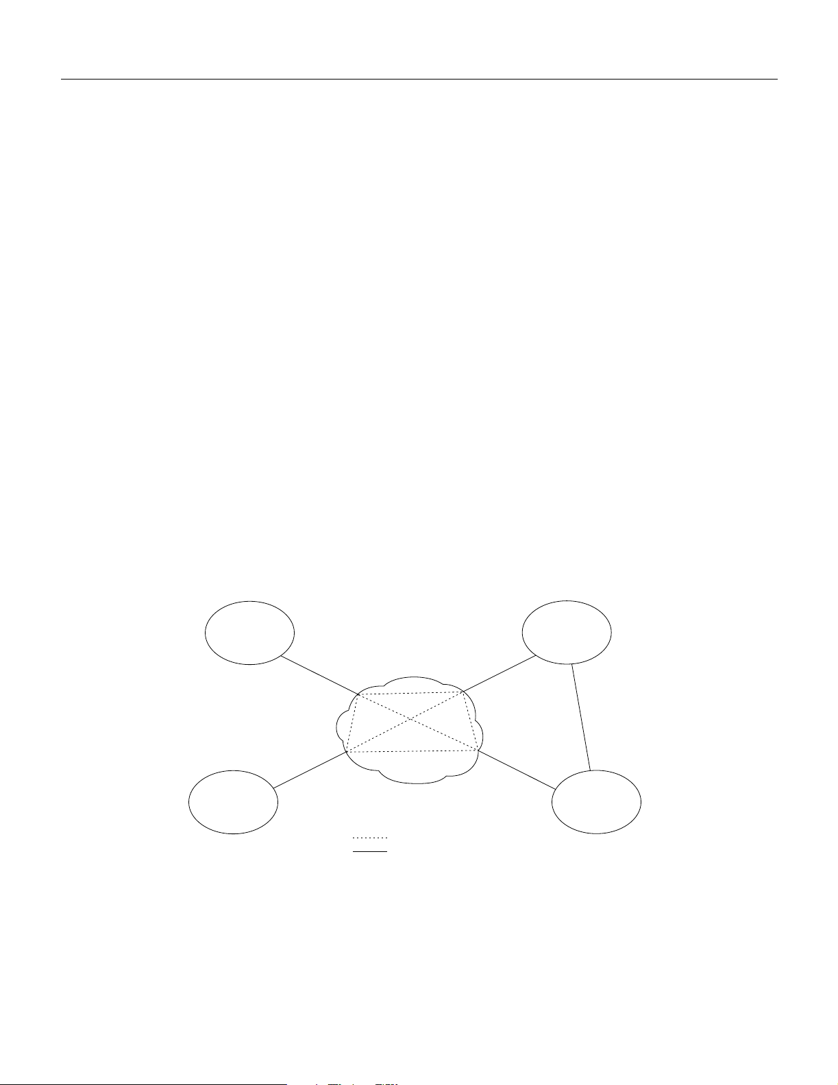
A virtual trunk may be defined as a “trunk over a public ATM service.” The trunk really doesn’t exist
as a physical line in the network. Rather, an additional level of reference, called a virtual trunk
number, is used to differentiate the virtual trunks found within a physical trunk port. Figure 1-5
shows four StrataCom sub-networks, each connected to a Public ATM Network via a physical line.
The Public ATM Network is shown linking all four of these subnetworks to every other one with a
full meshed network of virtual trunks. In this example, each physical line is configured with three
virtual trunks.
Figure 1-5 Virtual Trunking Example
Cisco
sub-network
ATM-UNI ATM-UNI
Public ATM
Cisco
sub-network
For further information on Virtual Trunking, refer to the Systems Manual and to the Command
Reference documentation. For sample configuration information, see Chapter 8, Configuration and
Management.
ATM-UNI ATM-UNI
Network
Virtual trunk
Leased line
Cisco
sub-network
Leased line
(backup)
Cisco
sub-network
H8227
1-10 BPX Service Node Reference
Page 45

Traffic and Congestion Management
The BPX provides ATM standard traffic and congestion management per ATM Forum TM 4.0 using
BXM cards.
The Traffic Control functions include:
• Usage Parameter Control (UPC)
• Traffic Shaping
• Connection Management Control
• Selective Cell Discarding
• Explicit Forward Congestion Indication (EFCI)
In addition to these standard functions, the BPX provides advanced traffic and congestion
management features including:
• Support for the full range of ATM service types per ATM Forum TM 4.0 by the BXM-T3/E3,
BXM-155, and BXM-622 cards on the BPX Service Node.
• FairShare, dedicated queue and rate controlled servers for each VPC/VCC at the network ingress.
• OptiClass, guarantees QoS for individual connections by providing up to 32 queues with
independent service algorithms for each trunk in the network.
Traffic and Congestion Management
FairShare
• AutoRoute, end-to-end connection management that automatically selects the optimum
connection path based upon the state of the network and assures fast automatic alternate routing
in the event of intermediate trunk or node failures.
• PNNI, a standards based routing protocol for ATM and Frame Relay switched virtual circuits
(SVCs).
• Frame Based Traffic Control (FBTC) for AAL5 connections, including early and partial frame
discard.
• ForeSight, an end-to-end closed loop rate based congestion control algorithm that dynamically
adjusts the service rate of VC queues based on network congestion feedback.
• ABR Standard with VSVD congestion control using RM cells and supported by BXM cards on
the BPX Service Node.
FairShare provides per-VC queueing and per-VC scheduling. FairShare provides fairness between
connections and firewalls between connections. Firewalls prevent a single non-compliant connection
from affecting the QoS of compliant connections. The non-compliant connection simply overflows
its own buffer.
The cells received by a port are not automatically transmitted by that port out to the network trunks
at the port access rate. Each VC is assigned its own ingress queue that buffers the connection at the
entry to the network. With ABR with VSVD or with ForeSight, the service rate can be adjusted up
and down depending on network congestion.
Network queues buffer the data at the trunk interfaces throughout the network according to the
connections class of service. Service classes are defined by standards-based QoS. Classes can consist
of the four broad service classes defined in the ATM standards as well as multiple sub-classes to each
of the four general classes. Classes can range from constant bit rate services with minimal cell delay
variation to variable bit rates with less stringent cell delay.
Introduction 1-11
Page 46

Traffic and Congestion Management
When cells are received from the network for transmission out a port, egress queues at that port
provide additional buffering based on the service class of the connection.
OptiClass
OptiClass provides a simple but effective means of managing the quality of service defined for
various types of traffic. It permits network operators to segregate traffic to provide more control over
the way that network capacity is divided among users. This is especially important when there are
multiple user services on one network.
Rather than limiting the user to the four broad classes of service initially defined by the ATM
standards committees, OptiClass can provide up to thirty-two classes of service (service subclasses)
that can be further defined by the user and assigned to connections. Some of the COS parameters
that may be assigned include:
• Minimum bandwidth guarantee per subclass to assure that one type of traffic will not be
preempted by another.
• Maximum bandwidth ceiling to limit the percentage of the total network bandwidth that any one
class can utilize.
• Queue depths to limit the delay.
• Discard threshold per subclass.
These class of service parameters are based on the standards-based Quality of Service parameters
and are software programmable by the user. The BPX provides separate queues for each traffic class.
AutoRoute
With AutoRoute, connections in StrataCom cell relay networks are added if there is sufficient
bandwidth across the network and are automatically routed when they are added. The user only
needs to enter the endpoints of the connection at one end of the connection and the IPX, IGX, and
BPX software automatically set up a route based on a sophisticated routing algorithm. This feature
is called AutoRoute. It is a standard feature on all StrataCom nodes.
System software automatically sets up the most direct route after considering the network topology
and status, the amount of spare bandwidth on each trunk, as well as any routing restrictions entered
by the user (e.g. avoid satellite links). This avoids having to manually enter a routing table at each
node in the network. AutoRoute simplifies adding connections, speeds rerouting around network
failures, and provides higher connection reliability.
Private Network to Network Interface
The Private Network-to-Network Interface (PNNI) protocol provides a standards-based dynamic
routing protocol for ATM and Frame Relay switched virtual circuits (SVCs). PNNI is an
ATM-Forum-defined interface and routing protocol which is responsive to changes in network
resources, availability, and will scale to large networks. PNNI is available on the BPX Service Node
when an Extended Services Processor (ESP) is installed. For further information about PNNI and
the ESP, refer to the Cisco StrataCom BPX Service Node Extended Services Processor Installation
and Operation.
Congestion Management, VS/VD
The BPX/IGX/IPX networks provide a choice of two dynamic rate based congestion control
methods, ABR with VS/VD and ForeSight. This section describes Standard ABR with VSVD.
1-12 BPX Service Node Reference
Page 47

Traffic and Congestion Management
Note ABR with VSVD is an optional feature that must be purchased and enabled on a single node
for the entire network.
When an ATM connection is configured for Standard ABR with VSVD per ATM Forum TM 4.0,
RM (Resource Management) cells are used to carry congestion control feedback information back
to the connection’s source from the connection’s destination.
The ABR sources periodically interleave RM cells into the data they are transmitting. These RM
cells are called forward RM cells because they travel in the same direction as the data. At the
destination these cells are turned around and sent back to the source as Backward RM cells.
The RM cells contain fields to increase or decrease the rate (the CI and NI fields) or set it at a
particular value (the explicit rate ER field). The intervening switches may adjust these fields
according to network conditions. When the source receives an RM cell it must adjust its rate in
response to the setting of these fields.
When spare capacity exists with the network, ABR with VSVD permits the extra bandwidth to be
allocated to active virtual circuits.
Congestion Management, ForeSight
The BPX/IGX/IPX networks provide a choice of two dynamic rate based congestion control
methods, ABR with VS/VD and ForeSight. This section describes ForeSight.
Note ForeSight is an optional feature that must be purchased and enabled on a single node for the
entire network.
ForeSight may be used for congestion control across BPX/IGX/IPX switches for connections that
have one or both end points terminating on other than BXM cards, for example ASI cards. The
ForeSight feature is a dynamic closed-loop, rate-based, congestion management feature that yields
bandwidth savings compared to non-ForeSight equipped trunks when transmitting bursty data across
cell-based networks.
ForeSight permits users to burst above their committed information rate for extended periods of time
when there is unused network bandwidth available. This enables users to maximize the use of
network bandwidth while offering superior congestion avoidance by actively monitoring the state of
shared trunks carrying Frame Relay traffic within the network.
ForeSight monitors each path in the forward direction to detect any point where congestion may
occur and returns the information back to the entry to the network. When spare capacity exists with
the network, ForeSight permits the extra bandwidth to be allocated to active virtual circuits. Each
PVC is treated fairly by allocating the extra bandwidth based on each PVC's committed bandwidth
parameter.
Conversely, if the network reaches full utilization, ForeSight detects this and quickly acts to reduce
the extra bandwidth allocated to the active PVCs. ForeSight reacts quickly to network loading in
order to prevent dropped packets. Periodically, each node automatically measures the delay
experienced along a Frame Relay PVC. This delay factor is used in calculating the ForeSight
algorithm.
Introduction 1-13
Page 48

Network Management
With basic Frame Relay service, only a single rate parameter can be specified for each PVC. With
ForeSight, the virtual circuit rate can be specified based on a minimum, maximum, and initial
transmission rate for more flexibility in defining the Frame Relay circuits.
ForeSight provides effective congestion management for PVC's traversing broadband ATM as well.
ForeSight operates at the cell-relay level that lies below the Frame Relay services provided by the
IPX. With the queue sizes utilized in the BPX, the bandwidth savings is approximately the same as
experienced with lower speed trunks. When the cost of these lines is considered, the savings offered
by ForeSight can be significant.
Network Management
BPX Service Node nodes provide one high-speed and two low-speed data interfaces for data
collection and network management. The high-speed interface is an Ethernet 802.3 LAN interface
port for communicating with a StrataView Plus NMS workstation. TCP/IP provides the transport and
network layer, Logical Link Control 1 is the protocol across the Ethernet port.
The low-speed interfaces are two RS-232 ports, one for a network printer and the second for either
a modem connection or a connection to an external control terminal. These low-speed interfaces are
the same as provided by the IPX nodes.
A StrataView Plus NMS workstation connects to the Ethernet (LAN) port on the BPX and provides
network management via SNMP. Statistics are collected by SV+ using the TFTP protocol. On IPX
shelves, Frame Relay connections are managed via the SV+ Connection Manager. On AXIS shelves,
the SV+ Connection Manager manages Frame Relay and ATM connections, and the Connection
Manager is used for AXIS shelf configuration
Each BPX Service Node can be configured to use optional low-speed modems for inward access.
For network troubleshooting assistance call Cisco TAC to report alarms remotely. If desired, another
option is remote monitoring or control of customer premise equipment through a window on the
StrataView Plus workstation.
Network Interfaces
Network interfaces connect the BPX node to other BPX, IGX, or IPX nodes to form a wide-area
network.
The BPX provides T3, E3, OC3/STM-1, and OC12/STM-4 trunk interfaces. The T3 physical
interface utilizes DS3 C-bit parity and the 53-byte ATM physical layer cell relay transmission using
the Physical Layer Convergence Protocol. The E3 physical interface uses G.804 for cell delineation
and HDB3 line coding. The BNI-155 card supports single-mode fiber (SMF), single-mode fiber long
reach (SMF-LR), and multi-mode fiber (MMF) physical interfaces. The BXM-155 cards support
SMF, SMFLR, and MMF physical interfaces. The BXM-622 cards support SMF and SMFLR
physical interfaces.
The design of the BPX permits it to support network interfaces up to 622 Mbps in the current release
while providing the architecture to support higher broadband network interfaces as the need arises.
Optional redundancy is on a one-to-one basis. The physical interface can operate either in a normal
or looped clock mode. And as an option, the node synchronization can be obtained from the DS3
extracted clock for any selected network trunk.
1-14 BPX Service Node Reference
Page 49

Service Interfaces
Service interfaces connect ATM customer equipment to the BPX. ATM User-to-Network Interfaces
(UNI) and ATM Network-to-Network Interfaces (NNI) terminate on the ATM Service Interface
(ASI) cards and on BXM OC-3 and OC-12 cards configured for as service interfaces (UNI access
mode). The ASI-1 card provides two T3 or E3 ports. The ASI-155 card OC3/STM-1 trunk interfaces
are single-mode fiber (SMF), single-mode fiber long reach (SMF-LR), and multi-mode fiber (MMF)
physical interfaces. The BXM-155 cards support SMF, SMFLR, and MMF physical interfaces. The
BXM-622 cards support SMF and SMFLR physical interfaces. The ASI and BXM cards support cell
relay connections that are compliant with both the physical layer and ATM layer standards.
The ATM Interface Shelf (AXIS) interfaces to the Broadband Network Interface (BNI) card, via a
T3 or E3 ATM STI interface, respectively, or via an OC3 interface. The AXIS provides a
concentrator for T1 or E1 Frame Relay and ATM connections to the BPX Service Node with the
ability to apply ForeSight across a connection from end-to-end. The AXIS also supports FUNI
(Frame Based UNI over ATM) connections.
Statistical Alarms and Network Statistics
The BPX Service Node system manager can configure alarm thresholds for all statistical type error
conditions. Thresholds are configurable for conditions such as frame errors, out of frame, bipolar
errors, dropped cells, and cell header errors. When an alarm threshold is exceeded, the NMS screen
displays an alarm message.
Network Management
Graphical displays of collected statistics information, a feature of the StrataView Plus NMS, are a
useful tool for monitoring network usage. Statistics collected on network operation fall into two
general categories:
• Node statistics
• Network trunk statistics
• Network Service, line statistics
• Network Service, port statistics
These statistics are collected in real-time throughout the network and forwarded to the StrataView
Plus workstation for logging and display. The link from the node to StrataView Plus uses a protocol
to acknowledge receipt of each statistics data packet. Refer to the StrataView Plus Operations
documentation, for more details on statistics and statistical alarms.
Node Synchronization
A BPX Service Node network provides network-wide, intelligent clock synchronization. It uses a
fault-tolerant network synchronization architecture recommended for Integrated Services Digital
Network (ISDN). The BPX Service Node internal clock operates as a Stratum-3 clock per ANSI
T1.101.
Since the BPX Service Node is designed to be part of a larger communications network, it is capable
of synchronizing to higher-level network clocks as well as providing synchronization to lower-level
devices. Any network access input can be configured to synchronize the node. Any external T1 or
E1 input can also be configured to synchronize network timing. A clock output allows synchronizing
an adjacent IPX or other network device to the BPX Service Node and the network. In nodes
equipped with optional redundancy, the standby hardware is locked to the active hardware to
minimize system disruption during system switchovers.
Introduction 1-15
Page 50

Node Availability
The BPX Service Node does not accept clock from an IPX. The BPX Service Node can be
configured to select clock from the following sources:
• External (T1/E1)
• Line (DS3/E3)
• Internal
Node Availability
Hardware and software components are designed to provide a node availability in excess of 99.99%.
Network availability will be much more impacted by link failure, which has a higher probability of
occurrence, than equipment failure.
Because of this, StrataCom switches are designed so that connections are automatically rerouted
around network trunk failures often before users detect a problem. System faults are detected and
corrective action taken often before they become service affecting. The following paragraphs
describe some of the features that contribute to network availability.
Node Redundancy
System availability is a primary requirement with the BPX Service Node. The designed availability
factor of a BPX Service Node is (99.99%) based on a node equipped with optional redundancy and
a network designed with alternate routing available. The system software, as well as firmware for
each individual system module, incorporates various diagnostic and self-test routines to monitor the
node for proper operation and availability of backup hardware.
Node Alarms
For protection against hardware failure, a BPX shelf can be equipped with the following redundancy
options:
• Redundant common control modules
• Redundant crosspoint switch matrixes
• Redundant high-speed data and control lines
• Redundant power supplies
• Redundant high-speed network interface cards
• Redundant service interface cards
If redundancy is provided for a BPX shelf, when a hardware failure occurs, a hot-standby module is
automatically switched into service, replacing the failed module. All cards are hot-pluggable, so
replacing a failed card in a redundant system can be performed without disrupting service.
Since the power supplies share the power load, redundant supplies are not idle. All power supplies
are active; if one fails, then the others pick up its load. The power supply subsystem is sized so that
if any one supply fails, the node will continue to be supplied with adequate power to maintain normal
operation of the node. The node monitors each power supply voltage output and measures cabinet
temperature to be displayed on the NMS terminal or other system terminal.
Each BPX shelf within the network runs continuous background diagnostics to verify the proper
operation of all active and standby cards, backplane control, data, and clock lines, cabinet
temperature, and power supplies. These background tests are transparent to normal network
operation.
1-16 BPX Service Node Reference
Page 51

Node Availability
Each card in the node has front-panel LEDs to indicate active, failed, or standby status. Each power
supply has green LEDs to indicate proper voltage input and output. An Alarm, Status, and Monitor
card collects all the node hardware status conditions and reports it using front panel LED indicators
and alarm closures. Indicators are provided for major alarm, minor alarm, ACO, power supply status,
and alarm history. Alarm relay contact closures for major and minor alarms are available from each
node through a 15-pin D-type connector for forwarding to a site alarm system.
BPX shelves are completely compatible with the network status and alarm display provided by the
optional StrataView Plus NMS workstation. In addition to providing network management
capabilities, it displays major and minor alarm status on its topology screen for all nodes in a
network. The StrataView Plus also provides a maintenance log capability with configurable filtering
of the maintenance log output by node name, start time, end time, alarm type, and user specified
search string.
Introduction 1-17
Page 52

Node Availability
1-18 BPX Service Node Reference
Page 53

CHAPTER
General Description
This chapter contains an overall physical and functional description of the BPX. The physical
description includes the BPX enclosure, power, and cooling subsystems. The functional description
includes an overview of BPX operation.
This chapter contains the following sections:
Physical Description
Functional Description
BPX Major Groups
2
Physical Description
The BPX is supplied as a stand-alone assembly. It may be utilized as a stand-alone ATM switch, or
it may be integrated at customer sites with one or more narrowband IPX nodes, multi-band IGX
nodes, AXIS shelves, and other access devices to provide network access to broadband backbone
network links for narrowband traffic. Cisco StrataCom and CPE service interface equipment can also
be co-located with the BPX and connect to its ATM service interfaces.
BPX Enclosure
The BPX enclosure is a self-contained chassis which may be rack mounted in any standard
19 inch rack or enclosure with adequate ventilation. It contains a single shelf which provides fifteen
slots for vertically mounting the BPX cards front and rear. See Figure 2-1 which illustrate the front
view of the BPX Shelf.
At the front of the enclosure (Figure 2-1) are 15 slots for mounting the BPX front cards. Once
inserted, the cards are locked in place by the air intake grille at the bottom of the enclosure. A
mechanical latch on the air intake grille must be released by using a screwdriver and the grille must
be tilted forward in order to remove or insert cards.
At the rear of the enclosure (Figure 2-2) is another series of card slots for mounting the rear plug-in
cards. These are held in place with two thumbscrews, top and bottom. A mid-plane, located between
the two sets of plug-in cards, is used for interconnect and is visible only when the cards are removed.
To provide proper cooling, it is essential that blank faceplates be installed in all unused slots. Failure
to do so will degrade node cooling and circuit card damage will result. The blank faceplates also
provide RFI shielding.
General Description 2-1
Page 54

Physical Description
Figure 2-1 BPX Cabinet Exterior Front View
17 3/4"
27"
Air intake
Slot #1
1 2 3
4 5 6 7 8 9 10 11 12 13 14
19"
Slot #15
22 3/4"
15
Extractor
handles
H8018
2-2 BPX Service Node Reference
Page 55

Figure 2-2 BPX Cabinet Exterior Rear View
Fans
Air
Exhaust
Slot #15
Back
Cards
L
M
–
3
/T
3
LM
–
3/T
3
LM
–
ASM
3/T
15
3
L
M
–
3/T3
14 13 12 11 10 7
L
M
–
3
/T3
L
M
–
3
/T
3
L
M
–
3
/T3
LM
–
3/T
3
LM
–
3/T
9
3
LM
–
BCC-B
3/T
8
3
LM
–
BCC-A
3/T
3
L
M
–
3
/T3
6
L
M
–
3
/T
5432
3
L
M
–
3/T
3
L
M
–
3/T
3
1
Physical Description
Slot #1
Node Cooling
A fan assembly, with three six-inch 48 VDC fans is mounted on a tray at the rear of the BPX shelf
(Figure 2-2). Air for cooling the cards is drawn through an air intake grille located at the bottom in
the front of the enclosure. Air passes up between the vertically-mounted cards and exhausts at the
top, rear of the chassis. All unused slots in the front are filled with blank faceplates to properly
channel airflow.
Node DC Powering
The primary power for a BPX node is -48 VDC which is bused across the backplane for use by all
card slots. DC-to-DC converters on each card convert the 48V to lower voltages for use by the card.
The 48 VDC input connects directly to the DC Power Entry Module (PEM). The DC Power Entry
Module () provides a circuit breaker and line filter for the DC input.
H8017
General Description 2-3
Page 56

Physical Description
Nodes may be equipped with either a single PEM or dual PEMs for redundancy. They are mounted
at the back of the node below the backplane. A conduit hookup box or an insulated cover plate is
provided for terminating conduit or wire at the DC power input. It is recommended that the source
of DC for the node be redundant and separately fused.
Figure 2-3 DC Power Entry Module Shown with Conduit Box Removed
ON
CB1
OFF
USE COPPER
CONDUCTORS ONLY
SAFETY
GROUND
+RTN
–48V
Plastic
Cover
DC Terminal
Block
Optional AC Power Supply Assembly
For applications requiring operation from an AC power source, an optional AC Power Supply
Assembly and shelf is available. It provides a source of –48 VDC from 208/240 VAC input. A shelf,
separate from the BPX shelf, houses one or two AC Power Supplies and mounts directly below the
node cabinet. This provides a secure enclosure for the power supply assemblies (supplies cannot be
removed without the use of tools).
Two of these supplies are usually operated in parallel for fail-safe redundant operation. The front of
the AC Power Supplies for the BPX includes two green LEDs to indicate correct range of the AC
input and the DC output for each individual supply (Figure 2-4).
H8019
2-4 BPX Service Node Reference
Page 57

Figure 2-4 AC Power Supply Assembly Front View
Card Shelf Configuration
There are fifteen vertical slots in the front of the BPX enclosure to hold plug-in cards (Figure 2-5).
The middle two slots, slots number 7 and number 8, are used for the primary and secondary
Broadband Controller Cards (BCC). The right-most slot, number 15, is used to hold the single
Alarm/Status Monitor Card. The other twelve slots, number 1 through number 6 and number 8
through number 14, can be used for the Network Interface and Service Interface cards.
Physical Description
Indicator
LEDS
DC
AC
H8145
General Description 2-5
Page 58

Physical Description
Figure 2-5 BPX Card Shelf Front View
General
13
act failstby
BCC/
PRI
status
status
13
13
port
port
act failstby
act failstby
card
card
BNI-3/T3
BNI-3/T3
81234
81234
purpose
card slots
1234567
status
status
status
13
act failstby
status
13
port
port
act failstby
card
card
BNI-3/T3
BNI-3/T3
81234
81234
13
port
port
act failstby
card
card
BNI-3/T3
BNI-3/T3
81234
81234
BCC-A8BCC-B
LAN
act failstby
card
BNI-3/T3
BCC-15
81234
81236
BCC/
SEC
LAN
act failstby
card
BCC-15
81236
status
port
card
BNI-3/T3
81234
purpose
card slots
9 101112131415
status
status
13
act failstby
status
13
13
port
port
act failstby
act failstby
card
card
BNI-3/T3
BNI-3/T3
81234
81234
13
act failstby
22222222222
port
card
BNI-3/T3
81234
General
ASM
ASM
status
status
status
13
13
major minor
2
port
port
alarms
AB
DC ok
ACO hist
ACO
history clear
act failstby
act failstby
card
BNI-3/T3
81234
act failstby
card
card
BNI-3/T3
ASM
81234
81237
2-6 BPX Service Node Reference
H8020
Page 59

Functional Description
ATM
ATM transmits broadband information using fixed length, relatively small, 53-byte cells which are
suitable for carrying both constant rate data (for example, voice and video) as well as bursty data.
ATM evolved from the Broadband Integrated Services Digital Network (B-ISDN) standard, which
in turn is an extension of ISDN. ISDN defines service and interfaces for public telecommunications
networks. B-ISDN utilizes a 7-layer reference model similar to the Open Systems Interconnection
(OSI) 7-layer architecture. ATM redefines the lower three levels as shown in Figure 2-6. These are
the Physical Layer, the ATM layer, and the ATM Adaptation Layer (AAL).
Figure 2-6 B-ISDN Model
Management plane
Control plane User plane
Functional Description
Physical Layer
Higher layer functions
AALs
(ATM
adaptation
layers)
Physical
layer
Convergence sublayer
(CS)
SAR
ATM layer
TC
PM
Service specific, e.g., FR-SSCS
Common part convergence
sublayer CPCS
Segmentation and reassembly
Cell header insert/extract
Cell multiplexing/demultiplexing
VPI/VCI addressing and translation
Generic flow control
Transmission convergence
Physical medium
H8021
The physical layer is divided into two parts, the Transmission Convergence sub-layer and the
Physical Medium sub-layer.
The Physical Medium sub-layer (PMD) handles processing specific to a particular physical layer,
such as transmission rate, clock extractions, etc.
The Transmission Convergence sub-layer (TC) extracts the information content from the physical
layer data format. This includes HEC generation and checking, extraction of cells from the data
stream, processing of idle cells, etc.
AT M L aye r
The ATM layer processes ATM cells. The ATM cell consists of a 5-byte header and a 48-byte
payload. The header contains the ATM cell address and other management information Figure 2-7.
General Description 2-7
Page 60

Functional Description
Figure 2-7 ATM Cell Format
53 byte cell
5 bytes 48 Byte payload
ATM cell
header
Information payload
H8146
ATM Cell Headers
There are two basic header types defined by the standards committees, a UNI header and a NNI
header; both are quite similar. Cisco has expanded on these header types to provide additional
features beyond those proposed for basic ATM service. Usage of each of the various cell header
types is described as follows:
• The UNI header (Figure 2-8) must be specified for each User-to-Network Interface. A UNI is any
interface between a user device, such as an ATM router, and an ATM network.
• The NNI header (Figure 2-9) must be specified for each Network-to-Network Interface. This is
used, for example, at the interface between a user’s private ATM network and a service provider’s
public ATM network.
• The STI header (Figure 2-10) is an extension of these two header types and is a Cisco StrataCom
Interface. This header type is used between Cisco StrataCom nodes to provide advanced network
features, including ForeSight, that improve performance, efficiency, and congestion control.
2-8 BPX Service Node Reference
Page 61

Figure 2-8 UNI Header
Bit — 87654321
Functional Description
Byte 1
Byte 2
Byte 3
Byte 4
Byte 5
Virtual circuit identifier
Header Error Control (HEC)
Virtual path identifierFlow control
Virtual circuit identifierVirtual path identifier
Payload typeVirtual circuit identifier
Cell
loss
priority
Figure 2-9 NNI Header
Bit — 87654321
Byte 1
Byte 2
Byte 3
Byte 4
Byte 5
Virtual path identifier
Virtual circuit identifierVirtual path identifier
Virtual circuit identifier
Payload typeVirtual circuit identifier
Header Error Control (HEC)
Cell
loss
priority
H8147
H8148
General Description 2-9
Page 62

Functional Description
Figure 2-10 STI Header
STI Header
87654321
HCS
VPI
PTI
CLP
HCF
VPI VCI
VCI Payload class
CC
FR
HCF: Header Control Field, a 01 indicates an STI Cell
VPI/VCI: Virtual Path/Virtual Channel Identifiers, same
as UNI and NNI.
Payload Class:
0001 Non-Timestamped Data/Constant BIt Rate
0010 High Priority/Variable Bit Rate
0011 Voice/Constant BIt Rate
0100 Bursty Data A/Variable BIt Rate
0101 Time-Stamped Data/Constant BIt Rate
0110 Bursty Data B/Variable BIt Rate
CC: Congestion Control
00: No report 10: Congestion
01: Uncongested 11: Severe Congestion
PTI, bits 4,3, and 2:
bit 4 = 0, user data cell;
bit 4 = 1, connection management cell
bit 3 = 0, No congestion experienced
bit 3 = 1, Congestion experienced
bit 2 = 0, for user data cell, indicates CPE information
bit 2 = 1, not used
PTI Description
Bits
432
000 User Data Cell no congestion experienced SDU Type 0 (CPE information)
001 User Data Cell no congestion experienced SDU Type 1
010 User Data Cell congestion experienced, SDU Type 0 (CPE information)
011 User Data Cell congestion experienced, SDU Type 1
100 Connection Management Cell, OAM F5 Segment Flow Related cell
101 Congestion Management Cell, OAM F5 End-to-End Flow related cell
110 Connection Management Cell, reserved for future use.
111 Connection Management Cell, reserved for future use.
F: ForeSIght Forward Congestion
Indication (FFCI).
Set to 1 if FECN in Frame is a 1.
or if incoming cell FFCI is a 1, or
egress queue experiences congestion.
R: Reserved
PTI: Payload Type Indicator
CLP: Cell Loss Priority. Same as for UNI
or NNI. The CLP bit is set to 1 if the
DE is set for a frame, or if the first
FastPacket in a frame has its CLP set.
H8149
The most important fields in all three ATM cell header types are the Virtual Path Identifier (VPI) and
a Virtual Circuit Identifier (VCI). The VPI identifies the route (path) to be taken by the ATM cell
while the VCI identifies the circuit or connection number on that path. The VPI and VCI are
translated at each ATM switch, they are unique only for a given physical link.
A 4-bit Generic Flow Control (GFC) field in the UNI header is intended to be used for controlling
user access and flow control. At present, it is not defined by the standards committees and is
generally set to all zeros.
A 3-bit Payload Type Indicator (PTI) field indicates the type of data being carried in the payload.
The first bit is a “0” if the payload contains user information and is a “1” if it carries connection
management information. The second bit indicates if the cell experienced congestion over a path. If
the payload is user information, the third bit indicates if the information is from Customer Premises
Equipment (CPE). The PTI field is identical for UNI/NNI/STI.
2-10 BPX Service Node Reference
Page 63

Functional Description
In the STI header (Figure 2-10), the Payload Class is used to indicate various classes of service and
BPX queues, for example, Opticlass, the enhanced class of service feature of the BPX. The ForeSight
Forward Congestion Indication, the F bit, is used by ForeSight for congestion status.
The Cell Loss Priority (CLP) bit follows the PTI bits in all header types. When set, it indicates that
the cell is subject to discard if congestion is encountered in the network. For Frame Relay
connections, depending on mapping considerations, the frame Discard Eligibility status is carried by
the CLP bit in the ATM Cell. The CLP bit is also set at the ingress to the network for all cells carrying
user data transmitted above the minimum rate guaranteed to the user.
ATM Cell Addressing
Each ATM cell contains a two-part address, VPI/VCI, in the cell header. This address uniquely
identifies an individual ATM virtual connection on a physical interface. VCI bits are used to identify
the individual circuit or connection. Multiple virtual circuits that traverse the same physical layer
connection between nodes are grouped together in a virtual path. The virtual path address is given
by the VPI bits. The Virtual Path can be viewed as a trunk that carries multiple circuits all routed the
same between switches
The VPI and VCI addresses may be translated at each ATM switch in the network connection route.
They are unique only for a given physical link. Therefore, they may be reused in other parts of the
network as long as care is taken to avoid conflicts.
The VCI field is 16 bits wide with UNI and NNI header types described earlier. This allows for a
total possible 65, 535 unique circuit numbers. The UNI header reserves 8 bits for VPI (256 unique
paths) while the NNI reserves 12 bits (4,096 unique paths) as it is likely that more virtual paths will
be routed between networks than between a user and the network. The STI header reserves 8 bits for
VCI and 10 bits for VPI addresses.
ATM Adaptation Layer
The purpose of the ATM Adaptation Layer (AAL) is to receive the data from the various sources or
applications and convert, or adapt, it to 48-byte segments that will fit into the payload of an ATM
cell. Since ATM benefits from its ability to accommodate data from various sources with differing
characteristics, the Adaptation Layer must be flexible.
Traffic from the various sources have been categorized by the standards committees into four general
classifications, Class A through Class D, as indicated in Table 2-1. This categorization is somewhat
preliminary and initial developments have indicated that it may be desirable to have more than these
initial four classes of service.
Table 2-1 Classes of Traffic and Associated AAL Layers
Traffic Class Class A Class B Class C Class D
Adaptation Layer
(AAL)
Connection Mode Connection-oriented Connection-oriented Connection-oriented Connectionless
End-to-End Timing
Relationship
Bit Rate Constant Variable Variable Variable
Examples Uncompressed
AAL-1 AAL-2 AAL-3/4
AAL-5
Yes Yes No No
voice, constant
bit-rate video
Compressed voice
and video
Frame Relay, SNA,
TCP-IP, E-mail
AAL-3/4
SMDS
General Description 2-11
Page 64

Functional Description
Initially, four different adaptation layers (AAL1 through AAL4) were envisioned for the four classes
of traffic. However, since AAL3 and AAL4 both could carry Class C as well as Class D traffic and
since the differences between AAL3 and AAL4 were so slight, the two have been combined into one
AAL3/4.
AAL3/4 is quite complex and carries a considerable overhead. Therefore, a fifth adaptation layer,
AAL5, has been adopted for carrying Class C traffic, which is simpler and eliminates much of the
overhead of the proposed AAL3/4. AAL5 is referred to as the Simple and Efficient Adaptation
Layer, or SEAL, and is used for Frame Relay data.
Since ATM is inherently a connection-oriented transport mechanism and since the early applications
of ATM will be heavily oriented towards LAN traffic, many of the initial ATM products are
implemented supporting the Class C Adaptation Layer with AAL5 Adaptation Layer processing for
carrying Frame Relay traffic.
The ATM Adaptation Layer consists of two sub-layers (Figure 2-6):
• Convergence Sub-Layer (CS)
• Segmentation and Reassembly Sub-Layer (SAR)
Data is received from the various applications layers by the Convergence Sub-Layer and mapped
into the Segmentation and Reassembly Sub-Layer. User information, typically of variable length, is
packetized into data packets called Convergence Sublayer Protocol Data Units (CS-PDUs).
Depending on the Adaptation Layer, these variable length CS-PDUs will have a short header, trailer,
a small amount of padding, and may have a checksum.
The Segmentation and Reassembly Sub-Layer receives the CS-PDUs from the Convergence
Sub-Layer and segments them into one or more 48-byte SAR-PDUs, which can be carried in the
48-byte ATM information payload bucket. The SAR-PDU maps directly into the 48-byte payload of
the ATM cell transmitted by the Physical Layer. Figure 2-11 illustrates an example of the Adaptation
Process.
Figure 2-11 SAR Adaptation Process
Variable Length
XXX Bytes
48 Bytes 48 Bytes 48 Bytes
Application Layer Information
CS – PDU
SAR – PDU
ATM Cells
H8022
2-12 BPX Service Node Reference
Page 65

IPX and IGX Trunk Interfaces to ATM
The IPX/IGX connect to a BPX or other ATM switch via an AIT/BTM T3 or E3 trunk. The
AIT(IPX) or BTM (IGX) can operate in several different addressing modes selected by the user
(Table 2-12 and Figure 2-13). To allow the IPX or IGX to be used in mixed networks with other ATM
switches, there are two other addressing modes available, Cloud Addressing Mode (CAM) and
Simple Addressing Mode (SAM).
BPX Addressing Mode
In the BPX Addressing Mode (BAM), used for all Cisco StrataCom networks, the system software
determines VPI and VCI values for each connection that is added to the network. The user enters the
beginning and end points of the connection and the software automatically programs routing tables
in each node that will carry the connection to translate the VPI/VCI address. The user does not need
to enter anything more. This mode uses the STI header format and can support all of the optional
Cisco StrataCom features.
Simple Addressing Mode
In the Simple Addressing Mode (SAM), the user must manually program the path whole address,
both VPI and VCI values.
Functional Description
Cloud Addressing Mode
The Cloud Addressing Mode (CAM) is used in mixed networks where the virtual path addresses are
programmed by the user and the switch decodes the VCI address. Both CAM and SAM utilize the
UNI header type.
Figure 2-12 ATM Cell Addressing Modes
Addressing Mode Hdr. Type Derivation of VPI/VCI Where Used
BAM-BPX Addressing
Mode
CAM—
Cloud Addressing Mode
SAM—
Simple Addressing Mode
STI VPI/VCI = Node Derived
Address
UNI VPI = User Programmed
VCI = Node Derived Address
UNI VPI/VCI = User Programmed IPX to IPX (or IGX) connections over networks
Between IPX (or IGX) and BPX nodes, or between
IPX (or IGX) nodes.
IPX to IPX (or IGX) connections over networks
using ATM switches that switch on VPI only. VPI is
manually programmed by user. Terminating IPX
converts VCI address to FastPacket address.
using ATM switches that switch where all routing is
manually programmed by user, both VPI and VCI.
General Description 2-13
Page 66

Functional Description
Figure 2-13 BAM, CAM, and SAM Configurations
BAM IGX BTM IPXAIT
BAM IPX AIT BPXBNI
CAM IPX AIT IPXAIT
SAM
Note: IPX with AIT card are interchangeable with IGX with BTM card in this diagram.
IPX AIT IGXBTM
FastPacket Adaptation to ATM
A specialized adaptation that is of particular interest to users of Cisco equipment is the adaptation of
IPX FastPackets to ATM cells. There are a large number of narrowband IPX networks currently in
existence that are efficiently carrying voice, video, data, and Frame Relay. A means must be
provided to allow these networks to grow by providing a migration path to broadband.
Since FastPackets are already a form of cell relay, the adaptation of FastPackets to ATM cells is
relatively simple.
Simple Gateway
With the Simple Gateway protocol, the AIT card in the IPX (or BTM in the IGX) loads 24-byte
FastPacket cells into ATM cells in ways that are consistent with each application. (Each of the two
FastPacket cells loaded into the ATM Cell is loaded in its entirety, including the FastPacket header.)
For example, two FastPackets can be loaded into one ATM cell provided they both have the same
destination. This adaptation is performed by the IPX AIT card or the IGX BTM card.
ATM cloud
VP switch
ATM cloud
VP/VC switch
H8150
The AIT (or BTM) is configured to wait a given interval for a second FastPacket to combine in one
ATM cell for each FastPacket type. The cell is transmitted half full if the wait interval expires. High
priority and non-time stamped packets are given a short wait interval. High priority FastPackets will
not wait for a second FastPacket. The ATM trunk interface will always wait for Frame Relay data
(bursty data) to send two packets. NPC traffic will always have two FastPackets in an ATM cell.
Complex Gateway, Frame Relay to ATM Network Interworking
Starting with Release 8.1, with the Complex Gateway capability, the FRSM card in the AXIS, the
AIT card in the IPX (or BTM card in the IGX) streams the Frame Relay data into ATM cells, cell
after cell, until the frame has been completely transmitted. Since only the data from the FastPacket
is loaded, the Complex Gateway is an efficient mechanism. Also, discard eligibility information
2-14 BPX Service Node Reference
Page 67
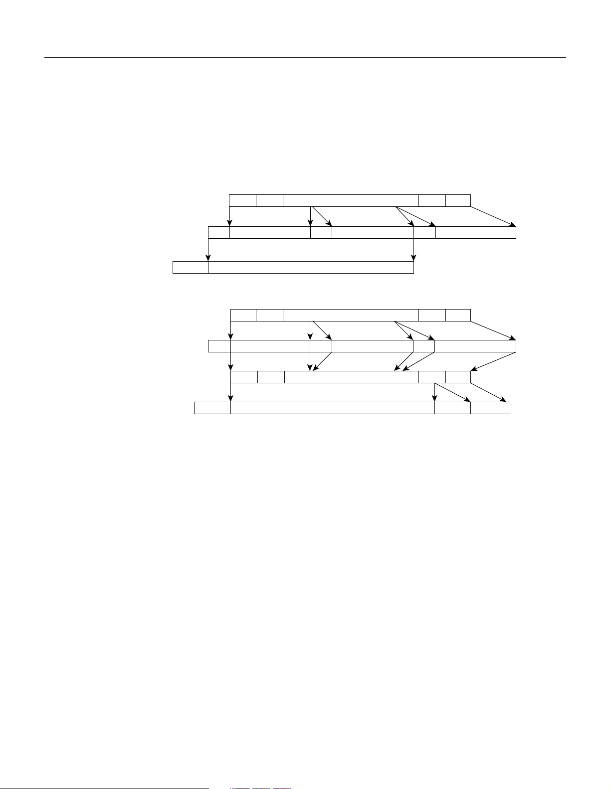
Functional Description
carried by the Frame Relay bit is mapped to the ATM cell CLP bit, and vice versa. See Chapter 13
for further information on Frame Relay to ATM interworking. A comparison of the simple gateway
and complex gateway formats is shown in Figure 2-14.
Figure 2-14 Simple and Complex Gateway Formats
Simple gateway (AIT card) :
Frame Relay frame
presented to FRP:
Built by FRP into
FastPackets:
ATM
cells:
Complex gateway (AIT Card) :
Frame Relay frame
presented to FRP:
Built by FRP into
FastPackets:
Back to Frame Relay
frame in AIT:
AAL-5 ATM
cells
generated
by AIT:
HDR
HDR HDR
HDR HDR CRC
HDR HDR HDR
HDR HDR Variable length CRC CRC
HDR 20 bytes HDR 20 bytes HDR 20 bytes
Variable length
20 bytes 20 bytes 20 bytes
48 Bytes
HDR CRC CRC
Variable lengthHDR
48 Bytes
CRC
H8228
General Description 2-15
Page 68

BPX Major Groups
BPX Major Groups
There are four major groups in the BPX. These major groups are listed in Table 2-2.
• Common Core
• Network Interface
• Service Interface
• Power Supplies
Table 2-2 lists these groups and their components along with a brief description of each.
Table 2-2 BPX Plug-In Card Summary
Card Card Name Where
BCC-32 Broadband Controller Card, operates with all versions of System
BCC-bc Back card (also known as LM-BCC) used only with the BCC-32. Back
BCC-3 Broadband Controller Card, operates with 7.X software versions
BCC-4 Broadband Controller Card, operates with 8.4 software and above.
BCC-3-bc Back card (also known as LM-BCC) used with BCC-3 or BCC-4. Back
ASM Alarm/Status Monitor Card. Front
LM - ASM Line Module - Alarm/Status Monitor. Back
BXM-T3/E3-8/12 T3/E3card with 8or 12 ports. Card is configured for use in either
BPX-T3/E3-8 Backcard for use with a BXM-T3/E3-8. Back
BPX-T3/E3-12 Backcard for use with a BXM-T3/E3-12. Back
BXM-155-4
BXM-155-8
MMF-155-4
SMF-155-4
SMFLR-155-4
MMF-155-8
SMF-155-8
SMFLR-155-8
BXM-622
BXM-622-2
Common Core Group
Front
Software Release. 7.0 and above, and requires 32 Mbyte RAM for
8.1 and later software. For redundancy configuration, installed as a
pair of BCC-32s. (System operation equivalent to BCC-3.)
Front
7.2.84 and above, and with 8.X System Software versions 8.1.12
and above. For redundancy configuration, installed as a pair of
BCC-3s. (System operation equivalent to BCC-32.)
Front
For redundancy configuration, installed as a pair of BCC-4s.
Provides 64 Mbyte of RAM and above. Supports 19.2 Gbps
performance of BXM cards.
Network Interface Group
Front
network interface or service access (UNI) mode and with either a
T3 or E3 interface.
BXM OC-3 cards with 1 OC-3/STM-1ports. Card is configured for
use in either network interface or service access (UNI) mode.
Backcards for BXM-155-4. Back
Backcards for BXM-155-8. Back
OC-12 card with 1or 2 OC-12/STM-4ports. Card is configured for
use in either network interface or service access (UNI) mode.
Back
Front
2-16 BPX Service Node Reference
Page 69

Table 2-2 BPX Plug-In Card Summary (Continued)
Card Card Name Where
SMF-622
Backcards for BXM-622. Back
SMFLR-622
SMF-622-2
Backcards for BXM-622-2. Back
SMFLR-622-2
SMFXLR Back
BNI - T3 Broadband Network Interface Card (with 3 T3 Ports). Front
LM - 3T3 Line Module - used with BNI-T3 for 3 physical T3 ports.
Back
(Configured for 3 ports)
BNI - E3 Broadband Network Interface Card (with 3 E3 Ports). Front
LM - 3E3 Line Module - used with BNI-E3 for 3 physical E3 ports.
Back
(Configured for 3 ports).
BNI-155 Broadband Network Interface Card (with 2 OC3c/STM-1 ports). Front
LM-2OC3-SMF OC3/STM-1 Interface Card, single mode fiber optic, used with
Back
either BNI-155 or ASI-155 front card.
LM-2OC3-SMFLR OC3/STM-1 Interface Card, single mode fiber optic long range,
Back
used with either BNI-155 or ASI-155.
LM-2OC3-MMF OC3/STM-1 Interface Card, multi-mode fiber optic (1 x 9 LED),
Back
used with either BNI-155 or ASI-155 front card.
Service Interface Group
ASI-1-2T3 ATM Service Interface Card (with 2 usable T3 ports). Front
LM - 3T3 Line Module - used with ASI-1-2T3 for 2 physical T3 ports.
Back
(Configured for 2 ports)
ASI-1-2E3 ATM Service Interface Card (with 2 usableE3 ports). Front
LM - 3E3 Line Module - used with BNI-E3 for 2 physical E3 ports.
Back
(Configured for 2 ports)
ASI-155 ATM Service Interface Card (with 2 OC3c/STM-1 ports). Front
LM-2OC3-SMF OC3/STM-1 Interface Card, SMF (single mode fiber optic) MMF
Back
(1x9 LED), used with either BNI-155 or ASI-155 front card.
LM-2OC3-MMF OC3/STM-1 Interface Card, multi-fiber mode (1 x 9 LED), used
Back
with BNI-155 or ASI-155.
LM-2OC3-SMFLR OC3/STM-1 Interface Card, single mode fiber optic long range,
Back
used with either BNI-155 or ASI-155.
Power Supply Group
48V DC Power Supply
Optional AC Power Supply
BPX Major Groups
General Description 2-17
Page 70

CHAPTER
BPX Common Core
This chapter contains a description of the common core group, comprising the Broadband Controller
Cards (BCCs), the Alarm/Status Monitor (ASM) card, associated backcards, and the StrataBus
backplane.
This chapter contains the following sections:
BPX Common Core Group
Broadband Controller Card (BCC-32, BCC-3, BCC-4)
Alarm/Status Monitor Card (ASM)
3
BPX StrataBus Backplane
BPX Common Core Group
The BPX Common Core group includes the Broadband Controller Card (BCC-3 and associated
BCC-3-bc backcard, or BCC-32 and associated BCC-b backcard), or BCC-4 and associated
BCC-3-c backcard, the Alarm/Status Monitor (ASM), a Line Module for the ASM card (LM-ASM),
and the StrataBus backplane (see Figure 3-1). The BCC-3 and BCC-32 are functionally equivalent
and support 9.6 Gbps operation, but use different backcards. The BCC-4 supports the 19.2 Gbps
operation of the BXM cards and provides 32M or 64M.
• ATM cell switching.
• Internal node communication.
• Remote node communication.
• Node synchronization.
• Network management communications (Ethernet), local management (RS-232).
• Alarm and status monitoring functions.
BPX Common Core 3-1
Page 71

Broadband Controller Card (BCC-32, BCC-3, BCC-4)
Broadband Controller Card (BCC-32, BCC-3, BCC-4)
The Broadband Controller Card is a microprocessor-based system controller and is used to control
the overall operation of the BPX node. The controller card is a front card that is usually equipped as
a redundant pair. Slots number 7 and number 8 are reserved for the primary and secondary (standby)
broadband controller cards. Each broadband controller front card requires a corresponding back
card.
• For non-redundant nodes, a single BCC is used in front slot number 7 with its appropriate
backcard.
• For redundant nodes, a pair of BCCs of matching type, are used in front slot numbers 7 and 8.
Note The three types of BCCs with their proper backcards may be operated together temporarily
for maintenance purposes, for example, replacing a failed controller card. Throughout a network,
individual BPX nodes may have either a single BCC-32, BCC-3, or BCC-4 controller card or a pair
of BCC-32 cards, a pair of BCC-3 cards, or a pair of BCC-4 cards.
Figure 3-1 Common Core Group Block Diagram
EXT/INT
clock
Broadband
Line
module-
BCC
controller
card
primary
NMS
port
Line
module-
BCC
Broadband
controller
card
redundant
Common
core
group
StrataBus backplane
Alarm
outputs
Line
module-
ASM
Alarm/
status
monitor
Interface
card
Interface
card
Interface
card
H8023
BPX Common Core 3-2
Page 72

Broadband Controller Card (BCC-32, BCC-3, BCC-4)
The BCC-3 and BCC-32 are functionally equivalent and the BCC-4 is similar except for some
additional features such as support of 19.6 Gbps operation. The term BCC is used in this manual to
refer to the functional operation of the Broadband Controller Card. When a difference in operation
does occur, the specific type of BCC is specified. This card group (see Figure 3-1) provides the
following functions:
Features
The Broadband Controller Card performs the following major system functions:
• Runs the system software for controlling, configuring, diagnosing, and monitoring the BPX
node.
• Contains the crosspoint switch matrix operating at 800 Mbps per serial link (BCC-32 or BCC-3)
or up to 1600 Mbps (BCC-4).
• Contains the arbiter which controls the polling each high-speed data port and grants the access
to the switch matrix for each port with data to transfer.
• Generates Stratum-3 system clocking and can synchronize it to either a selected trunk or an
external clock input.
• Communicates configuration and control information to all other cards in the same node over the
backplane communication bus.
• Communicates with all other nodes in the network.
• Provides a communications processor for an Ethernet LAN port plus two low-speed data ports.
The BCC-bc provides the physical interface for the BCC-32, and the BCC-3-bc provides the
physical interface for the BCC-3 and BCC-4.
Each Broadband Controller Card includes the following:
• 68EC040 processor operating at 33 MHz.
• 32 Mb of DRAM for running system software (BCC-32 and BCC-3), 32 Mb or 64 MB option
for BCC-4.
• 4 Mb of Flash EEPROM for downloading system software.
• 512 Kbps of BRAM for storing configuration data.
• EPROM for firmware routines.
• 68302 Utility processor.
• SAR engine processor operating at 33 MHz.
• Communication bus interface.
• HDLC processor for the LAN connection interface.
• Two RS-232 serial port interfaces.
3-3 BPX Service Node Reference
Page 73

Functional Description
The BPX is a space switch. It employs a crosspoint switch for individual data lines to and from each
port. The switching fabric in each BPX node consists of three elements for the BCC-32, BCC-3 and
for the BCC-4 (see Figure 3-2 and Figure 3-3):
• Central Arbiter on each BCC.
• Crosspoint Switch.
— 16 X 16 Crosspoint Switching Matrix on each BCC (12 X 12 used) for BCC-32 and BCC-3.
— 16 X 32 Crosspoint Switching Matrix on each BCC (2 X [12 X 12]) used for BCC-4.
• Serial Interface and LAN Interface Modules on each BCC and on each Function Module.
The arbiter polls each card to see if it has data to transmit. It then configures the crosspoint switching
matrix to make the connection between the two cards. Each connection is unidirectional and has a
capacity of 800 Mbps (616.7 Mbps for cell traffic plus the frame overhead).
Since there are 16 X 16 (BCC-32 or BCC-3) or 16 X 32 (BCC-4) independent crosspoints and only
15 cards, the switch fabric is non-blocking. However, only one connection at a time is allowed to an
individual card. The BPX cell switching is not synchronized to any external clocks; it runs at its own
rate. No switch fabric clocks are used to derive synchronization nor are these signals synchronized
to any external sources.
Broadband Controller Card (BCC-32, BCC-3, BCC-4)
Each card contains a Switch Interface Module (SIM) which merely provides a standardized interface
between the card and the data lines and polling buses. The SIM responds to queries from the BCC
indicating whether it has data ready to transmit.
With the BPX equipped with two BCCs, the cell switching is completely redundant in that there are
always two arbiters, two crosspoint switches, two completely independent data buses, and two
independent polling buses.
The BCC incorporates non-volatile flash EEPROM which permits new software releases to be
downloaded over the network and battery-backup RAM (BRAM) for storing user system
configuration data. These memory features maintain system software and configuration data even
during power failures, eliminating the need to download software or reconfigure after the power
returns.
Node clocking is generated by the BCC. Since the BPX resides as an element in a
telecommunications network, it is capable of synchronizing to higher-stratum clocking devices in
the network and providing synchronization to lower stratum devices. The BCC can be synchronized
to any one of three different sources under software control:
• An internal, high-stability oscillator
• Derived clock from a BNI module (no IPX clock sources allowed)
• An external clock source connected directly to the BPX
The BCC clock circuits provide clocking signals to every other card slot. If a function card needs to
synchronize its physical interface to the BPX clock, it can use this timing signal to derive the proper
reference frequency. These reference frequencies include DS1, E1, DS3, and E3.
BPX Common Core 3-4
Page 74

Broadband Controller Card (BCC-32, BCC-3, BCC-4)
Figure 3-2 BCC-32 and BCC-3 Block Diagram
I/O
module 1
SIU
I/O
module 2
SIU
TX data-2A
RX data-2A
TX data-12A
RX data-12A
I/O
module 12
SIU
TX data-1B
RX data-1B
TX data-2B
TX data-1A
RX data-1A
Polling bus-A
Polling bus-B
BCC-A
Xpoint switch
Arbiter
Arbiter
SIU
SIU
RX data-2B
TX data-12B
RX data-12B
Xpoint switch
BCC-A
H8151
3-5 BPX Service Node Reference
Page 75

Figure 3-3 BCC-4 Block Diagram
Broadband Controller Card (BCC-32, BCC-3, BCC-4)
I/O
module 1
DRSIU
I/O
module 2
DRSIU
S
TX data-2A
RX data-2A
TX data-12A
RX data-12A
s6392
I/O
module 12
DRSIU
TX data-1B
RX data-1B
TX data-2B
TX data-1A
RX data-1A
Polling bus-A
Polling bus-B
BCC-A
Arbiter
Arbiter
SIU
SIU
Front Panel Description
The BCC front panel has four LEDs, three card status LEDs, and a LAN LED. (See Figure 3-4 and
Table 3-1.)
Table 3-1 BCC Front Panel Indicators
No Indicator Function
1 LAN Indicates there is data activity over the Ethernet LAN port.
2 card - act Card active LED indicates this BCC is on-line and actively controlling
3 card - stby Card standby LED indicates this BCC is off-line but is ready to take over
4 card - fail Card fail LED indicates this BCC has failed the internal self-test routine
the node.
control of the node at a moments notice.
and needs to be reset or replaced.
RX data-2B
TX data-12B
RX data-12B
BCC-A
16 x 32 Xpoint switch 16 x 32 Xpoint switch
S6393
BPX Common Core 3-6
Page 76

Broadband Controller Card (BCC-32, BCC-3, BCC-4)
Figure 3-4 BCC Front Panel
LAN
BCC
LAN
card
act failstby
card
act failstby
H8024
3-7 BPX Service Node Reference
Page 77

The BCC runs self-tests continuously on internal functions in the background and if a failure is
detected, the fail LED is lighted. If the BCC is configured as a redundant pair, the off-line BCC is
indicated by the lighted stby LED. The stby LED also flashes when a software download or standby
update is in progress. The LAN LED indicates activity on the Ethernet port.
19.2Gbps Operation with the BCC-4
In order to operate the BPX Service Node at 19.2 Gbps the following is required:
• A 19.2 Gbps backplane
• BCC-4 or later controller cards
• One or more BXM cards
• Release 8.4.00 or later switch software
• A backplane NOVRAM that is programmed to identify the backplane as a 19.2 Gbps backplane.
Switch software will not allow node operation at 19.2 Gpbs unless it can read the backplane
NOVRAM to verify that the backplane is a 19.2 Gbps backplane.
The 19.2 backplane can be visually identified by the small white card slot fuses at the bottom rear of
the backplane. These fuses are approximately 1/4 inch high and 1/8 inch wide. The 9.6 Gbps
backplane does not have these fuses. If the BPX Service Node is a late model, then a 19.2 Gbps
backplane is installed. This can be verified by running the dspbpnv command which will display
“Word #2 =0001” if the backplane NOVRAM has been programmed. If anything else is displayed,
visually check the backplane for the fuses.
Broadband Controller Card (BCC-32, BCC-3, BCC-4)
If the backplane is a 19.2 Gbps backplane, but the backplane NOVRAM has not been set to display
Word #2 =0001, then the cnfbpnw command may be used to program the NOVRAM as follows:
Step 1 Enter cnfbpnv, and the response should be:
Are you sure this is a new backplane (y/n).
Step 2 Enter y
Step 3 Confirm that the change has been made by entering dspbpnv to confirm the response:
Word #2 =0001
Note If for some reason the change does not take place, it will be necessary to change the backplane
NOVRAM. Contact Customer Service.
Step 4 Enter switchcc in order for the change to be recognized by the switch software.
If the backplane is not a 19.2 Gbps backplane, then it will be necessary to install a 19.2 Gbps
backplane to obtain 19.2 Gbps operation. Contact Customer Service.
Back Cards for the BCC-3 and BCC-32
The backcards for the Broadband Controller Card serve as an interface between the BPX node and
the BPX network management system. For the BCC-32, the backcard is the BCC-bc. For the BCC-3
and BCC-4, the backcard is the BCC-3-bc. (These cards are also known as the BCC backcards). The
BPX Common Core 3-8
Page 78

Broadband Controller Card (BCC-32, BCC-3, BCC-4)
BCC-3 and the BCC-32 are functionally interchangeable, while the BCC-4 provides additional
features such as support for 19.2 Mbps operation by the BXM cards. Both BCCs in a node should
be of the same type. The backcard provides the following interfaces:
• An 802.3 AIU (Ethernet) interface for connecting the node to a StrataView Plus NMS.
• A serial RS-232 Control Port for connecting to a VT100-compatible terminal or modem.
• A serial RS-232 Auxiliary Port for connecting to an external printer.
• External clock inputs at T1 or E1 rates, output at 8 kHz.
The face plate connectors are described in Table 3-2 and Table 3-3 and shown in Figure 3-5. For
information on cabling, refer to Appendix B, BPX Cabling Summary.
Table 3-2 Backcard (Line Module) for BCC-32, Connectors
BCC-C
Connector
CONTROL A DB25 connector for a VT100 or equivalent terminal for a basic terminal connection using
AUXILIARY A DB25 connector for a system printer. This is a one-way, RS232 outgoing port.
XFER TMG DB15 connector that supplies an 8-kHz timing signal (RS422 type output that is
EXT TMG A 75-ohm BNC connection for clock input. An E1 source with 75 ohm impedance typically
EXT TMG DB15 connector for a primary and optional redundant external source of system clock. A T1
LAN A DB15 Ethernet LAN connection for connecting to a StrataView Plus NMS. A terminal or
Table 3-3 Back Card (Line Module) for BCC-3 & 4, Connectors
BCC-C
Function
command line interface commands. Can also be connected to a dial-in modem for remote
service support or other network management dial-up access. This is a bidirectional RS232
communications port. This is not used for SV+ Network Management; the LAN connector is
used for SV+ Network Management.
synchronized to the BPX system clock.) This signal can be used to synchronize a co-located
IPX.
uses this connector. If the shield on the cable needs grounding, slide the BCC back card out
and jumped connector JP1 across its two pins.
source with 100 ohm impedance or an E1 source with 100/120 ohm impedance typically use
this connector.
NMS other than SV+ can also be connected to the BPX LAN port via Ethernet. However,
only the SV+ NMS provides full management configuration and statistics capabilities via
SNMP and TFTP.
BCC-3-C
Connector
CONTROL A DB25 connector for a VT100 or equivalent terminal for a basic terminal connection
AUXILIARY A DB25 connector for a system printer. This is a one-way, RS232 outgoing port.
LAN A DB15 Ethernet LAN connection for connecting to a StrataView Plus NMS. A terminal
3-9 BPX Service Node Reference
BCC-3-C
Function
using command line interface commands. Can also be connected to a dial-in modem for
remote service support or other network management dial-up access. This is a
bidirectional RS232 communications port. This is not used for SV+ Network
Management; the LAN connector is used for SV+ Network Management.
or NMS other than SV+ can also be connected to the BPX LAN port via Ethernet.
However, only the SV+ NMS provides full management configuration and statistics
capabilities via SNMP and TFTP.
Page 79

Broadband Controller Card (BCC-32, BCC-3, BCC-4)
BCC-3-C
Connector
EXT TMG A 75-ohm BNC connection for clock input. An E1 source with 75 ohm impedance
EXT 1 TMG DB15 connector for a primary and optional redundant external source of system clock. A
EXT 2 TMG Provides for an external clock source redundant to the EXT 1 TMG source.
BCC-3-C
Function
typically uses this connector. If the shield on the cable needs grounding, slide the BCC
back card out and jumped connector JP1 across its two pins.
T1 source with 100 ohm impedance or an E1 source with 100/120 ohm impedance
typically use this connector.
BPX Common Core 3-10
Page 80

Broadband Controller Card (BCC-32, BCC-3, BCC-4)
Figure 3-5 BCC-3-bc or BCC-c Face Plate Connectors
C
O
N
T
Control Port
R
O
L
(DB25)
A
U
X
I
L
I
Auxiliary Port
A
R
(DB25)
Y
X
F
E
R
T1 or E1
T
M
External timing out
G
(DB15)
E
X
T
External timing
T
M
(E1, BNC)
G
E
X
T
T1 or E1
T
M
External timing in
G
(DB15)
C
O
N
T
Control Port
R
O
L
(DB25)
A
U
X
I
L
I
Auxiliary Port
A
R
(DB25)
Y
L
A
Ethernet for
N
Cisco WAN Manager
(DB15)
E
X
T
External timing
T
M
(E1, BNC)
G
E
X
T
1
External timing 1
T
(DB15)
M
G
BCC15-BC BCC-3-BC
Another function of the line module back card is to provide two low-speed, serial communications
ports (Table 3-3). The first port (CONTROL) is a bidirectional port used for connecting the BPX to
a local terminal or to a modem for a remote terminal “dial-in” connection. The second port
(AUXILIARY) is an output only and is typically used to connect to a log printer.
The SV+ NMS is connected to the LAN port on the BCC backcards. When control is provided via
an Ethernet interface, the node IP address is configured with the cnflan command for the BPX node,
and the back cards are Y-cable connected to an AUI adapter (individual cables and AUIs may also
be used for each LAN port). The LAN port of the primary Broadband Control Card is active. If the
3-11 BPX Service Node Reference
BCC
L
A
Ethernet for
N
Cisco WAN Manager
(DB15)
BCC-3
BC
E
X
T
2
T
M
G
External timing 2
(DB15)
H8025
Page 81

secondary Broadband Control Card becomes primary (active), then its LAN port becomes active.
The SV+ workstation will automatically try to restore communications over the LAN and will
interface with the newly active Broadband Controller Card.
For small networks, one SV+ workstation is adequate to collect statistics and provide network
management. For larger networks additional SV+ workstations may be required. Refer to the Cisco
StrataView Plus Operations Guide for more information.
Alarm/Status Monitor Card
The Alarm/Status Monitor (ASM) card is a front card and a member of the BPX Common Core
group. Only one is required per node and it is installed in slot 15 of the BPX shelf. It is used in
conjunction with an associated back card, the Line Module for the ASM (LM-ASM) card. The ASM
and LM-ASM cards are non-critical cards used for monitoring the operation of the node and not
directly involved in system operation. Therefore, there is no provision or requirement for card
redundancy.
Features
The ASM card provides a number of support functions for the BPX including:
Alarm/Status Monitor Card
• Telco compatible alarm indicators, controls, and relay outputs.
• Node power monitoring (including provision for optional external power supplies).
• Monitoring of shelf cooling fans.
• Monitoring of shelf ambient temperature.
• Sensing for the presence of other cards that are installed in the BPX shelf.
Functional Description
There are four significant circuits controlled by the ASM processor: alarm, power supply monitor,
fan and temperature monitor, and card detection. The alarm monitor controls the operation of the
front panel alarm LEDs and ACO and history pushbuttons as well as the alarm relays which provide
dry contact closures for alarm outputs to customer connections. BPX system software commands the
ASM card to activate the major and minor alarm indicators and relays.
The power supply monitor circuit monitors the status of the -48V input to the shelf on each of the
two power buses, A and B. The status of both the A bus and B power bus is displayed on the ASM
front panel.
Each of the three cooling fans is monitored by the fan monitor circuit which forwards a warning to
the BPX system software if any fan falls below a preset RPM. Cabinet internal temperature is also
monitored by the ASM which sends the temperature to the system software so it may be displayed
on the NMS terminal. The range that can be displayed is 0 degrees to 60 degrees Centigrade.
Front Panel Description
The front panel displays the status of the node and any major or minor alarms that may be present.
Figure 3-6 illustrates the front panel of the ASM card. Each front panel feature is described in
Table 3-4.
BPX Common Core 3-12
Page 82

Alarm/Status Monitor Card
Table 3-4 ASM Front Panel Controls and Indicators
No
1 alarms LEDs A red major alarm and a yellow minor alarm indicator to display the status
2 dc LEDs Two-green LEDs displaying the status of the two dc power busses on the
3 ACO/hist LEDs ACO LED (yellow) lights when the front panel ACO pushbutton is
4 ACO switch When operated, releases the audible alarm relay.
5 history clear switch Extinguishes the history LED if the alarm condition has cleared. If the
6 card status LEDs Active (green) indicates card is on-line and clear of alarms. Standby
Controls/
Indicator Function
of the local node. In general, a major alarm is service-affecting whereas a
minor alarm is a non-service affecting failure.
Stratabus backplane. On–indicates voltage within tolerance. Off–indicates
an out-of-tolerance voltage.
operated. History LED (green) indicates an alarm has been detected by the
ASM at some time in the past but may or may not be clear at present time.
alarm is still present when the history clear switch is thrown, the history
LED will stay lit.
(yellow) indicates card is off-line. Fault (red) indicates a card failure is
detected by the card self-test diagnostics.
3-13 BPX Service Node Reference
Page 83

Figure 3-6 ASM Front Panel Controls and Indicators
status
Alarm/Status Monitor Card
status
alarms
DC ok
card
ASM
major minor
AB
ACO hist
ACO
history clear
act failstby
alarms
major minor
DC ok
AB
ACO hist
ACO
history clear
card
act failstby
H8026
BPX Common Core 3-14
Page 84

Alarm/Status Monitor Card
Line Module for the Alarm/Status Monitor Card
The Line Module for the Alarm/Status Monitor Card (LM-ASM) is a back card to the ASM card. It
provides a simple connector panel for interfacing to the customer alarm system. It is not required for
system and ASM operation and must be installed in back slot number 15.
Figure 3-7 illustrates the face plate of the LM-ASM which contains a single subminiature connector
(Table 3-5). The Alarm Relay connector provides dry-closure (no voltage) relay contact outputs.
Table 3-5 LM-ASM Face Plate Connectors
Connector/
No
1 ALARM RELAYS A DB15 connector for alarm relay outputs. See Chapter 3 or Appendix C
Indicator Function
for pinouts.
3-15 BPX Service Node Reference
Page 85

Figure 3-7 LMI-ASM Face Plate
Alarm/Status Monitor Card
ASM
A
L
A
R
M
R
E
L
A
Y
S
Alarm Relays
(DB15)
H8027
BPX Common Core 3-16
Page 86

Alarm/Status Monitor Card
BPX StrataBus 9.6 and 19.2 Gbps Backplanes
The BPX Service Node may be equipped with a backplane that supports either a 9.6 or 19.2 Gbps
operation. The 19.2 Gbps backplane can physically be identified by the card slot fuses on the bottom
rear of the backplane. Further information is provided in the BPX Service Node Reference.
All BPX modules are interconnected by the BPX StrataBus backplane physically located between
the front card slots and the back card slots. Even though the ATM data paths to/from the switching
fabric and the interface modules are individual data connections, there are also a number of system
bus paths used for controlling the operation of the BPX node. The StrataBus backplane, in addition
to the 15 card connectors, contains the following signal paths:
• ATM crosspoint wiring—individual paths used to carry ATM trunk data between both the
network interface and service interface module(s) and the crosspoint switching fabric.
• Polling bus—used to carry enable signals between the BCC and all network interface modules.
• Communications bus—used for internal communications between the BCC and all other cards
in the node.
• Clock bus—used to carry timing signals between the BCC and all other system cards.
• Control bus—enables either the A bus wiring or B bus wiring.
All StrataBus wiring is completely duplicated and the two sets of bus wiring operate independently
to provide complete redundancy. Either the A side wiring or B side wiring is enabled at any particular
time by signals on the Control bus.
3-17 BPX Service Node Reference
Page 87

CHAPTER
Network Interface (Trunk) Cards
This chapter contains a description of the BPX network interface (trunk) cards, including the
Broadband Network Interface (BNI) and associated backcards.
This chapter contains the following sections:
BPX Network Interface Group
BXM Cards, Trunk Mode Summary
Broadband Network Interface Cards (BNI-T3 and BNI-E3)
4
T3 and E3 Line Modules (LM-3T3 and LM-3E3)
Broadband Network Interface Cards, BNI-155
OC3, Line Modules (SMF, SMFLR, & MMF)
Y-Cabling of BNI Backcard, SMF-2-BC9
BPX Network Interface Group
The BPX network interface group of cards provides the interface between the BPX and the ATM
network (Figure 4-1). The BNI series of cards (DS3, E3, and OC3) are described in this chapter. The
BXM card trunk operation is briefly described in this chapter with additional information provided
in a later chapter. The BXM cards may be configured for either trunk or service (port UNI) mode. In
trunk mode they provide BPX network interfaces.
BXM Cards, Trunk Mode Summary
The BXM card sets supports T3/E33, OC-3/STM-1 or OC-12/STM-4 interfaces, and provide the
capacity to meet the needs of emerging bandwidth driven applications. The BXM cards provide high
speed ATM connectivity, flexibility, and scalability. The card sets are comprised of a front card that
provides the processing, management, and switching of ATM traffic and a back card that provides
the physical interface for the card set.
A BXM port may be configured to operate as either a trunk or UNI port. The BXM OC-12 back cards
support either Single Mode Fiber (SMF) or Single Mode Fiber Long Reach (SMFLR). The BXM
OC-3 back cards support either Multi-Mode Fiber (MMF), Single Mode Fiber (SMF), or Single
Mode Fiber Long Reach (SMFLR). The BXM-T3/E3 supports T3 1.544 Mbps and E3 34.368 Mbps
interfaces.
For a further description of the BXM cards see to Chapter 6, “BXM T3/E3, 155, and 622”.
Network Interface (Trunk) Cards 4-1
Page 88
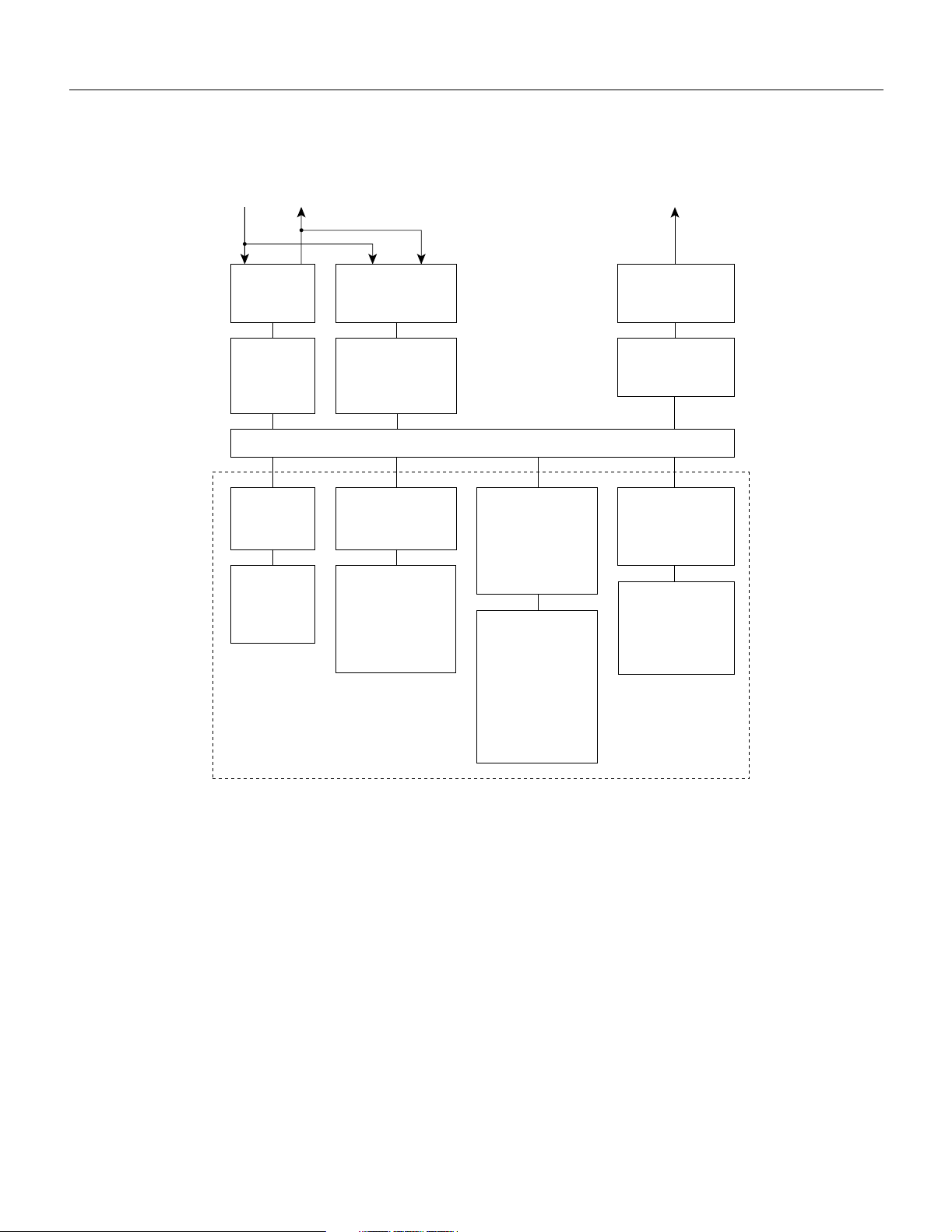
Broadband Network Interface Cards (BNI-T3 and BNI-E3)
Figure 4-1 BPX Network Interface Group
EXT/INT
clock
BPX network interface group
NMS
port
Line
module-
BCC
Broadband
controller
card
primary
Interface
card
BNI
Back card
LM 3T3
or
LM 3E3
LM-2OC3-SMF,
LM-2OC3-SMFLR,
LM-2OC3-MMF,
BXM-622-SMF
Line
module-
BCC
Broadband
controller
card
redundant
Interface
card
BNI-155
Back card
or
StrataBus backplane
Interface card
BXM-T3/E3
8 or 12 port
BXM-155
4 or 8 port
Back card
8 or 12 port
BPX-T3/E3
4 or 8 port
BXM-155-MMF,
BXM-155-SMF,
BXM-155-SMFLR
Alarm
outputs
Line
module-
ASM
Alarm/
status
monitor
Interface card
BXM-622
or
or
or
or
BXM-622-2
Back card
1 or 2 port
BXM-622-SMF
or
BXM-622-SMFLR
S6155
Broadband Network Interface Cards (BNI-T3 and BNI-E3)
The BNI-T3 and BNI-E3 interface the BPX with ATM T3 and E3 broadband trunks, respectively.
These ATM trunks may connect to either another BPX, an IPX equipped with an AIT card, or an
AXIS Shelf.
The BNI-3T3 back card provides three DS3 interfaces on one card while the BNI-E3 back card
provides three E3 interface ports. The BNI back card types are very similar differing only in the
electrical interface and framing. Any of the 12 general purpose slots can be used to hold these cards.
Each BNI operates as a pair with a corresponding Line Module back card.
4-2 BPX Service Node Reference
Page 89

Features
Broadband Network Interface Cards (BNI-T3 and BNI-E3)
A summary of features for the BNI cards include:
• BNI-T3 provides three broadband data ports operating at 44.736 Mbps.
BNI-E3 provides three broadband data ports operating at 34.368 Mbps.
• BNI T3 trunks can transmit up to 96,000 cells per second.
BNI E3 trunks can transmit up to 80,000 cells per second.
• BNI-T3 utilizes the Switched Megabit Data Service (SMDS) Physical Layer Convergence
Protocol (PLCP).
• BNI-E3 utilizes the CCITT G.804 framing format.
• T3 and E3 provide up to 32 class-based queues for each port.
• 24,000 cell transmit buffer per port.
• 800 Mbps backplane speed.
• Two-stage priority scheme for serving cells.
• Synchronize the electrical interface to either the line or the BPX system timing.
• Recover timing from the line for synchronizing the BPX node timing.
• Accumulates trunk statistics for T3, E3, and OC3.
• Optional 1:1 card redundancy using Y-cable configuration for BNI T3 and E3.
Functional Description
The BNI T3 and E3 cards are functionally alike except for the two different electrical interfaces. See
Figure 4-2 illustrating the main functional blocks in the BNI-3T3 card.
The DS3 port interface on the BNI-T3 card is the DS3 Function Block, a Physical Layer Protocol
Processor (PLPP) custom semiconductor device, which implements the functions required by the
DS3 PLCP as defined in various AT&T technical advisories. This VLSI device operates as a
complete DS3 transmitter/receiver. Each BNI-3T3 has three of these devices, one for each of the
DS3 ports on the card.
Egress
In the transmit direction (from the BPX switching matrix towards the transmission facility, referred
to as egress), the BNI performs the following functions:
• Software controlled line buildout to match up to 900 feet (275 meters) of ABAM cable.
• Receives incoming cells from the switch matrix on the BCC.
• Queues and serves the cells based on the class-of-service algorithm.
• Sets congestion indication (EFCN) in cell header when necessary.
• Adds frame sync pattern and PLCP or G.804 overhead and transmits cells onto the T3 or E3
trunk.
Network Interface (Trunk) Cards 4-3
Page 90

Broadband Network Interface Cards (BNI-T3 and BNI-E3)
Ingress
In the receive direction (from the transmission facility towards the BPX switching matrix, sometimes
referred to as ingress), the BNI performs the following functions:
• Receives incoming ATM cells from the DS3 transmission facility, stripping the framing and
overhead from the received bit stream.
• Determines the address of the incoming cells by scanning the Virtual Path Identifier (VPI)/Virtual
Circuit Identifier (VCI) in the cell header.
• Queues the cells for transmission through the switch matrix.
• Extracts receive timing from the input framing and makes it available for node timing. Line can
operate in looped timing mode.
• Recovers clock and data from the bipolar B3ZS (T3) or HDB3 (E3) line signal and converts data
to unipolar.
Figure 4-2 Simplified BNI-T3, BNI-E3 Block Diagram
Comm.
bus
interface
Control
& admin.
processor
BNI-3E3 only
G.832 framer
E3 xmtr/rcvr
E3 #1
StrataBus backplane
Serial
interface
module
(SIM)
Network
address
table
Queue service
engine #1
Queue service
engine #2
Queue service
engine #3
G.832 framer
E3 xmtr/rcvr
G.832 framer
E3 xmtr/rcvr
BNI-3T3 only
DS3 function
block (PLPP)
DS3 function
block (PLPP)
DS3 function
block (PLPP)
E3 #2
E3 #3
DS3 #1
DS3 #2
DS3 #3
H8153
4-4 BPX Service Node Reference
Page 91

Broadband Network Interface Cards (BNI-T3 and BNI-E3)
Some of the functions performed by the PLPP in the BNI-3T3 include:
• PLPP— Receiver Side
— Provides frame sync for either the M23 or C-bit parity frame format.
— Provides alarm detection and accumulates B3ZS code violations, framing errors, parity
errors, C-bit parity errors, and far end bit error (FEBE) events.
— Detects far end alarm channel codes, yellow alarm, and loss of frame.
— Provides optional cell descrambling, header check sequence (HCS) error detection, and cell
filtering.
— Small receive FIFO buffer for incoming cells.
• PLPP—Transmitter Side
— Inserts proper frame bit sequence into outgoing bit stream.
— Inserts proper alarm codes to be transmitted to the far end.
— Provides optional ATM cell scrambling, HCS generation and insertion, and programmable
null cell generation.
— Small transmit FIFO for outgoing cells.
Bandwidth Control
In the BNI-3E3 the PLPP is replaced by a G.804 framer. The E3 framer obtains end-to-end
synchronization on the Frame Alignment bytes. And a E3 transmitter/receiver replaces the DS3
transmitter/receiver for the BNI-3E3.
Another major BNI function is queuing of the ATM cells waiting to be transmitted to the network
trunk. This is controlled by the Queue Service Engine. There are 32 queues for each of the three ports
to support 32 classes of service, each with its programmable parameters such as minimum
bandwidth, maximum bandwidth, and priority. Queue depth is constantly monitored to provide
congestion notification (EFCN) status. The Queue Service Engine also implements a discard
mechanism for the cells tagged with Cell Loss Priority.
The destination of each cell is contained in the Virtual Path Identifier/Virtual Circuit Identifier
VPI/VCI) field of the cell header. This is translated to a Logical Connection Number via table lookup
in the Network Address Table. Both terminating and through connections can coexist on a port.
A Serial Interface Module (SIM) provides cell interface to the StrataBus backplane. This operates at
800 Mbps. It provides a serial-to-parallel conversion of the data and loopback and pseudo-random
bit generation for test purposes.
Both BNI-T3 and BNI-E3 cards support two clock modes that are selected by the system operator
through software control. Normal clocking uses receive clock from the network or user device for
incoming data and supplies transmit clock for outgoing data. The clock obtained can be used to
synchronize the node if desired. Loop timing uses receive clock from the network for the incoming
data and turns that same clock around for timing the transmit data to the network or connecting CSU.
The transmit bandwidth can be throttled down for certain applications. For example, when
interfacing with an IPX E3 ATM Trunk Card, the trunk transmit rate is limited to 40,000
cells/second. If a T2 trunk adapter is used, the trunk transmit rate is limited to 14,000 cells/second.
Network Interface (Trunk) Cards 4-5
Page 92

Broadband Network Interface Cards (BNI-T3 and BNI-E3)
Loopbacks and Diagnostics
There are two types of self-tests that may be performed. A non-disruptive self test is automatically
performed on a routine basis. A more complete, disruptive test may be initiated manually when a
card failure is suspected. If the card self-test detects a failure, the card status LEDs displays an
indication of the failure type (Table 4-5).
Several loopback paths are provided. A digital card loopback path, used by the node for self-test,
loops the data at the serial DS3 or E3 interface back towards the node. A digital line loopback loops
the data at the electrical transmitter/receiver at the card output. Internally, the PLPP circuit in the
BNI-T3 has several loopbacks for use by diagnostic routines.
There are several loopback paths within the BNI for testing. A digital loopback at the DS3 or E3
transmitter/receiver to check both the transmit and receive signal paths in the near-end BNI card.
These loopbacks loop the signal in both directions, towards the StrataBus as well as towards the
output. Therefore, they can be used to support both near end and far end maintenance loopback
testing. On the BNI-3T3, there is a digital loopback capability to the PLPP processor used for the
internal self test to basically check the operation of the signal processor.
Once a trunk has been assigned to a BNI card but before it is made active (upped), it is put in a
loopback mode and a diagnostic test is continuously performed. This loopback is disruptive so it
cannot be performed on a card that has an active trunk. This diagnostic test checks the data path
through the BNI out to the BCC, through the switch matrix, and back to the BNI. Active trunks are
constantly checked by the Communications Fail test routine which is part of system software.
Front Panel Indicators
The lower section of the BNI front panel (Figure 4-3) has a three-section, multicolored LED to
indicate the card status. The card status LED is color-coded as indicated in Table 4-1. At the upper
portion of the front panel, there is a three-section multicolored LED to indicate the status of the three
ports on the BNI. Types of failures are indicated by various combinations of the card status indicators
as indicated in Table 4-2.
Table 4-1 BNI Front Panel Status Indicators
Status LED color Status Description
Port off Trunk is inactive and not carrying data.
Card green (act) Card is on-line and one or more trunks on the card have been upped. If off,
green Trunk is actively carrying data.
yellow Trunk is in remote alarm.
red Trunk is in local alarm.
card may be operational but is not carrying traffic.
yellow (stby) Card is off-line and in standby mode (for redundant card pairs). May not
have any upped trunks. If blinking, indicates card firmware or
configuration data is being updated.
red (fail) Card failure; card has failed self-test and/or is in a reset mode.
4-6 BPX Service Node Reference
Page 93

Broadband Network Interface Cards (BNI-T3 and BNI-E3)
Figure 4-3 BNI-3T3 Front Panel (BNI-3E3 appears the same except for name)
status
port
1
2
status
port
card
ASI-2T3
1
act failstby
2
card
act failstby
H8028
Network Interface (Trunk) Cards 4-7
Page 94

T3 and E3 Line Modules (LM-3T3 and LM-3E3)
Table 4-2 BNI Front Panel Card Failure Indications
act stby fail Failure Description
on off on Non-fatal error detected; card is still active.
off on on Non-fatal error detected; card is in standby mode.
off blinking on Fatal error detected; card is in a reboot mode.
on on on Card failed boot load and operation is halted.
T3 and E3 Line Modules (LM-3T3 and LM-3E3)
The Line Modules for the BNI-T3 and BNI-E3 front cards are back cards used to provide a physical
interface to the transmission facility. The LM-3T3 is used with the BNI-T3 and the LM-3E3 with the
BNI-3E3. The Line Module connects to the BNI through the StrataBus midplane. Two adjacent
cards of the same type can be made redundant by using a Y-cable at the port connectors. All three
ports on a card must be configured the same.
Refer to Figure 4-4, Figure 4-5, and Table 4-3 which describe the faceplate connectors of the
LM-3T3 and LM-3E3. There are no controls or indicators.
The LM-3T3 provides the following features:
• BNC connectors for 75-ohm unbalanced signal connections to the transmit and receive of each
of the three ports.
• Transformer isolation from the trunk lines.
• Metallic relays for line loopback when in standby mode.
A final node loopback is found at the end of the LM-3T3 or LM-3E3 card. This is a metallic loopback
path that uses a relay contact closure. It is a near-end loopback path only; the signal is looped at the
final output stage back to circuits in the node receive side. It is only operated when the corresponding
front card is in standby.
Table 4-3 LM-3T3 and LM-3E3 Connectors
No Connector Function
1 PORT 1 RX - TX BNC connectors for the transmit and receive T3/E3 signal to/from ATM
trunk 1.
2 PORT 2 RX - TX BNC connectors for the transmit and receive T3/E3 signal to/from ATM
trunk 2.
3 PORT 3 RX - TX BNC connectors for the transmit and receive T3/E3 signal to/from ATM
trunk 3.
4-8 BPX Service Node Reference
Page 95

Figure 4-4 LM-3T3 Face Plate, Typical
T3 and E3 Line Modules (LM-3T3 and LM-3E3)
R
X
PORT 1
PORT 2
PORT 3
Port 1
T
X
R
X
RX
TX
Port 2
T
X
R
X
RX
TX
Port 3
T
X
RX
TX
LM–
3/T3
H8030
Network Interface (Trunk) Cards 4-9
Page 96

T3 and E3 Line Modules (LM-3T3 and LM-3E3)
Figure 4-5 LM-3E3 Face Plate, Typical
R
X
PORT 1
PORT 2
PORT 3
Port 1
T
X
R
X
RX
TX
Port 2
T
X
R
X
RX
TX
Port 3
T
X
RX
TX
4-10 BPX Service Node Reference
LM–
3/E3
H8031
Page 97

Broadband Network Interface Cards, BNI-155
Broadband Network Interface Cards, BNI-155
The BNI-155 interfaces the BPX with ATM OC3/STM-1 broadband trunks. The ATM trunk may
connect to either another BPX or customer CPE equipped with an ATM OC3/STM-1 interface.
There are three BNI-155 back cards, the LM-2OC3-SMF for single-mode fiber intermediate range,
the LM-2OC3-SMFLR for single-mode fiber long range, and the LM-2OC3-MMF for multi-mode
fiber. Any of the 12 general purpose slots can be used to hold these cards. These backcards may also
be used with the ASI-155.
Features
A summary of features for the BNI-155 cards include:
• LM-OC3-SMF and LM-OC3-MMF cards provide two ports, each operating at 155.52 Mbps.
• Up to 353,208 cells per second.
• Up to 12 class-based queues for each port.
• 8 K cell ingress (receive) VBR buffer.
• 32 K cell egress (transmit) buffers.
Overview
• 800 Mbps backplane speed.
• Two-stage priority scheme for serving cells.
• Accumulates trunk statistics for OC3/STM-1.
• Optional 1:1 card redundancy using Y-cable configuration for BNI-155.
Egress
In the transmit direction (from the BPX switching matrix towards the transmission facility, referred
to as egress), the BNI performs the following functions (Figure 4-6):
• Receives incoming cells from the switch matrix on the BCC.
• Serves the cells based on the class-of-service algorithm.
• Sets congestion indication (EFCN) in cell header when necessary.
Ingress
In the receive direction (from the transmission facility towards the BPX switching matrix, referred
to as ingress), the BNI performs the following functions (Figure 4-6):
• Receives incoming ATM cells from the OC3 transmission facility, stripping the framing and
overhead from the received bit stream.
• Determines the address of the incoming cells by scanning the Virtual Path Identifier/Virtual
Circuit Identifier (VPI/VCI) in the cell header.
Network Interface (Trunk) Cards 4-11
Page 98

Broadband Network Interface Cards, BNI-155
Functional Description
In the egress direction, the BNI-155 has 2 Queue Service Engine (QSEs) which provide each of the
ports with 12 programmable queues with selectable parameters such as minimum bandwidth,
priority, and maximum bandwidth. The BNI queues are based on a class of service algorithm. The
BNI supports the following trunk queues:
• Vo i c e
• Non-Time Stamped
• Time Stamped
• Bursty Data A
• Bursty Data B
• High Priority (Network Management Traffic)
• CBR
• VBR
In the ingress direction, the BNI-155 has 2 Cell Input Engines (CIEs) that convert the incoming cell
headers to the appropriate connection ID based on input from a Network Address Table.
The Serial Interface Unit (SIU) provides the BNI with an 800 Mbps cell interface to the StrataBus.
It provides serial-to-parallel conversion of data, along with loopback and test signal generation
capabilities.
The Line Interface Unit (LIU) performs the following ingress functions:
• Provides framing detection and synchronization.
• Provides the ability to extract timing from the incoming signal, and use it as a receive clock for
incoming data, while providing transmit clock in the other direction. Alternatively, loop timing
can be used to turn the receive clock back around to be used as a transmit clock. The receive clock
may also be used to synchronize the node.
• Detects alarms, frame errors, and parity errors.
• Detects far end errors, including framing errors, and yellow alarm indications.
• Provides optional cell descrambling, header error check (HEC), and idle cell filtering.
• Provides a small FIFO buffer for incoming cells.
• Provides optical to electrical conversion.
4-12 BPX Service Node Reference
Page 99

Broadband Network Interface Cards, BNI-155
The Line Interface Unit (LIU) performs the following egress functions:
• Inserts the appropriate framing into the outgoing bit stream.
• Inserts any alarm codes for transmission to the far end.
• Provides optional cell scrambling, HEC generation, and idle cell insertion.
• Provides a small FIFO buffer outing cells.
• Provides electrical to optical conversion.
Figure 4-6 Simplified BNI-155 Block Diagram
StrataBus
Egress
(from BCC
switching
matrix)
Front Panel Indicators
The BNI-155 front panel (Figure 4-7) has a three-section, multicolored “card” LED to indicate the
card status. The card status LED is color-coded as indicated in Table 4-4. A three-section
multicolored “port” LED indicates the status of the two ports on the BNI-155. Types of failures are
indicated by various combinations of the card status indicators as indicated in Table 4-5.
Ingress
(to BCC
switching
matrix)
CommBus
Iinterface
Serial
Interface
Unit
(SIU)
Control/Admin
processor
Network
address table
CIE port 1
CIE port 2
LIU = Line Interface Unit
CIE = Cell Input Engine
QSE = Queue Service Engine
LIU port 1
QSE port 1
LIU port 2
QSE port 2
H8229
Network Interface (Trunk) Cards 4-13
Page 100

Broadband Network Interface Cards, BNI-155
Table 4-4 BNI-155 Front Panel Status Indicators
Status LED color Status Description
port off Trunk is inactive and not carrying data.
green Trunk is actively carrying data.
yellow Trunk is in remote alarm.
red Trunk is in local alarm.
card green (act) Card is on-line and one or more trunks on the card have been upped. If
yellow (stby) Card is off-line and in standby mode (for redundant card pairs). May not
red (fail) Card failure; card has failed self-test and/or is in a reset mode.
Table 4-5 BNI Front Panel Card Failure Indications
act stby fail Failure Description
on off on Non-fatal error detected; card is still active.
off on on Non-fatal error detected; card is in standby mode.
off blinking on Fatal error detected; card is in a reboot mode.
on on on Card failed boot load and operation is halted.
off, card may be operational but is not carrying traffic.
have any upped trunks. If blinking, indicates card firmware or
configuration data is being updated.
4-14 BPX Service Node Reference
 Loading...