

Page 1
Cisco Small Business 200 Series Smart Switch
Administration Guide Release 1.2.7
ADMINISTRATION
GUIDE
Page 2

Contents
Table of Contents
Chapter 1: Getting Started 1
Starting the Web-based Switch Configuration Utility 1
Quick Start Switch Configuration 5
Interface Naming Conventions 5
Window Navigation 7
Chapter 2: Viewing Statistics 11
Viewing Ethernet Interfaces 11
Viewing Etherlike Statistics 12
Viewing 802.1X EAP Statistics 13
Managing RMON 15
Chapter 3: Managing System Logs 18
Setting System Log Settings 18
Setting Remote Logging Settings 20
Viewing Memory Logs 21
Chapter 4: Managing System Files 23
Types of System Files 23
Upgrade/Backup Firmware/Language 27
Downloading or Backing-up a Configuration or Log 29
Viewing Configuration Files Properties 32
Copying Configuration Files 33
DHCP Auto Configuration 34
Chapter 5: General Administrative Information 38
System Information 38
Switch Models 40
Rebooting the Switch 42
Cisco Small Business 200 Series Smart Switch Administration Guide 2
Page 3

Contents
Monitoring the Fan Status and Temperature 43
Defining Idle Session Timeout 44
Pinging a Host 44
Chapter 6: System Time 46
System Time Options 46
SNTP Modes 48
Configuring System Time 49
Chapter 7: Managing Device Diagnostics 56
Testing Copper Ports 56
Displaying Optical Module Status 58
Configuring Port and VLAN Mirroring 59
Viewing CPU Utilization and Secure Core Technology 61
Chapter 8: Configuring Discovery 63
Configuring Bonjour Discovery 63
LLDP and CDP 64
Configuring LLDP 65
Configuring CDP 86
Chapter 9: Port Management 95
Configuring Ports 95
Setting Basic Port Configuration 96
Configuring Link Aggregation 98
Configuring Green Ethernet 106
Chapter 10: Smartports 113
Overview 113
What is a Smartport 114
Smartport Types 114
Cisco Small Business 200 Series Smart Switch Administration Guide 3
Page 4

Contents
Smartport Macros 117
Macro Failure and the Reset Operation 118
How the Smartport Feature Works 119
Auto Smartport 120
Error Handling 124
Default Configuration 124
Relationships with Other Features and Backwards Compatibility 125
Common Smartport Tasks 125
Web GUI 127
Built-in Smartport Macros 132
Chapter 11: Managing Power-over-Ethernet Devices 156
PoE on the Switch 156
Configuring PoE Properties 158
Configuring the PoE Power, Priority, and Class 159
Chapter 12: VLAN Management 163
VLANs 163
Configuring Default VLAN Settings 166
Creating VLANs 167
Configuring VLAN Interface Settings 168
Defining VLAN Membership 170
Voice VLAN 174
Chapter 13: Configuring the Spanning Tree Protocol 187
STP Flavors 187
Configuring STP Status and Global Settings 188
Defining Spanning Tree Interface Settings 190
Configuring Rapid Spanning Tree Settings 192
Cisco Small Business 200 Series Smart Switch Administration Guide 4
Page 5

Contents
Chapter 14: Managing MAC Address Tables 195
Configuring Static MAC Addresses 196
Managing Dynamic MAC Addresses 196
Chapter 15: Configuring Multicast Forwarding 199
Multicast Forwarding 199
Defining Multicast Properties 202
Adding MAC Group Address 204
Adding IP Multicast Group Addresses 206
Configuring IGMP Snooping 207
MLD Snooping 209
Querying IGMP/MLD IP Multicast Group 212
Defining Multicast Router Ports 213
Defining Forward All Multicast 214
Defining Unregistered Multicast Settings 215
Chapter 16: Configuring IP Information 217
Management and IP Interfaces 217
Configuring ARP 229
Domain Name Systems 231
Chapter 17: Configuring Security 235
Defining Users 236
Configuring RADIUS 239
Configuring Management Access Authentication 241
Defining Management Access Method 242
Configuring TCP/UDP Services 247
Defining Storm Control 248
Configuring Port Security 250
Configuring 802.1X 252
Cisco Small Business 200 Series Smart Switch Administration Guide 5
Page 6

Contents
Denial of Service Prevention 259
Chapter 18: Using the SSL Feature 261
SSL Overview 261
Dependencies On Other Features 261
Default Settings and Configuration 262
SSL Server Authentication Settings 262
Chapter 19: Secure Sensitive Data 264
Introduction to the SSD Feature 264
SSD Management 265
SSD Properties 270
Configuration Files 271
Encryption of Sensitive Data 278
SSD Management Channels 279
Menu CLI and Password Recovery 280
Configuring SSD 280
282
Chapter 20: Configuring Quality of Service 283
QoS Features and Components 284
Configuring QoS - General 285
.Managing QoS Statistics 294
Cisco Small Business 200 Series Smart Switch Administration Guide 6
Page 7

Getting Started
This section provides an introduction to the web-based configuration utility, and
covers the following topics:
• Starting the Web-based Switch Configuration Utility
• Quick Start Switch Configuration
• Interface Naming Conventions
• Window Navigation
Starting the Web-based Switch Configuration Utility
1
This section describes how to navigate the web-based switch configuration utility.
If you are using a pop-up blocker, make sure it is disabled.
Browsers have the following restrictions:
• If you are using older versions of Internet Explorer, you cannot directly use
an IPv6 address to access the switch. You can, however, use the DNS
(Domain Name System) server to create a domain name that contains the
IPv6 address, and then use that domain name in the address bar in place of
the IPv6 address.
• If you have multiple IPv6 interfaces on your management station, use the
IPv6 global address instead of the IPv6 link local address to access the
switch from your browser.
Cisco Small Business 200 Series Smart Switch Administration Guide 7
Page 8

Getting Started
Starting the Web-based Switch Configuration Utility
Launching the Configuration Utility
To open the web-based configuration utility:
STEP 1 Open a Web browser.
STEP 2 Enter the IP address of the switch you are configuring in the address bar on the
browser, and then press Enter. The
NOTE When the switch is using the factory default IP address of 192.168.1.254, its power
LED flashes continuously. When the switch is using a DHCP assigned IP address or
an administrator-configured static IP address, the power LED is on solid.
Logging In
Login
1
page opens.
The default username is cisco and the default password is cisco. The first time
that you log in with the default username and password, you are required to enter
a new password.
NOTE If you have not previously selected a language for the GUI, the language of the Login
page is determined by the language(s) requested by your browser and the
languages configured on your switch. If your browser requests Chinese, for
example, and Chinese has been loaded into your switch, the Login page is
automatically displayed in Chinese. If Chinese has not been loaded into your
switch, the Login page is displayed in English.
The languages loaded into the switch have a language and country code (en-US,
en-GB and so on). For the Login page to be automatically displayed in a particular
language, based on the browser request, both the language and country code of
the browser request must match those of the language loaded on the switch. If the
browser request contains only the language code without a country code (for
example: fr). The first embedded language with a matching language code is
taken (without matching the country code, for example: fr_CA).
To log in to the device configuration utility:
STEP 1 Enter the username/password. The password can contain up to 64 ASCII
characters. Password-complexity rules are described in the Setting Password
Complexity Rules section of the Configuring Security chapter.
STEP 2 If you are not using English, select the desired language from the Language drop-
down menu. To add a new language to the switch or update a current one, refer to
the Upgrade/Backup Firmware/Language section.
Cisco Small Business 200 Series Smart Switch Administration Guide 8
Page 9

Getting Started
Starting the Web-based Switch Configuration Utility
STEP 3 If this is the first time that you logged on with the default user ID (cisco) and the
default password (cisco) or your password has expired, the
Page opens. See Password Expiration for additional information.
STEP 4 Choose whether to select Disable Password Complexity Enforcement or not.
For more information on password complexity, see the Setting Password
Complexity Rules section.
STEP 5 Enter the new password and click Apply.
When the login attempt is successful, the Getting Started page opens.
If you entered an incorrect username or password, an error message is displayed
and the Login page remains displayed on the window.
1
Change Password
Select Don’t show this page on startup to prevent the
being displayed each time that you log on to the system. If you select this option,
the System Summary page is opened instead of the Getting Started page.
Getting Started
page from
HTTP/HTTPS
You can either open an HTTP session (not secured) by clicking Log In, or you can
open an HTTPS (secured) session, by clicking Secure Browsing (HTTPS). You are
asked to approve the logon with a default RSA key, and an HTTPS session is
opened.
For information on how to configure HTTPS, see SSL Server Authentication
Settings.
Password Expiration
The New Password page is displayed:
• The first time you access the switch with the default username cisco and
password cisco. This page forces you to replace the factory default
password.
• When the password expires, this page forces you to select a new
password.
Cisco Small Business 200 Series Smart Switch Administration Guide 9
Page 10

Getting Started
Starting the Web-based Switch Configuration Utility
Logging Out
By default, the application logs out after ten minutes of inactivity. You can change
this default value as described in the Defining Idle Session Timeout section in the
General Administrative Information and Operations chapter.
CAUTION Unless the Running Configuration is copied to the Startup Configuration, rebooting
the switch will remove all changes made since the last time the file was saved. Save
the Running Configuration to the Startup Configuration before logging off to
preserve any changes you made during this session.
A flashing red X icon to the left of the Save application link indicates that Running
Configuration changes have not yet been saved to the Startup Configuration file.
The flashing can be disabled by clicking on the Disable Save Icon Blinking button
on the Copy/Save Configuration page
1
When the switch auto-discovers a device, such as an IP phone (see Chapter 10,
“What is a Smartport”), and it configures the port appropriately for the device.
These configuration commands are written to the Running Configuration file. This
causes the Save icon to begin blinking when the you log on even though you did not
make any configuration changes.
When you click Save, the Copy/Save Configuration page is displayed. Save the
Running Configuration file by copying it to the Startup Configuration file. After this
save, the red X icon and the Save application link are no longer displayed.
To logout, click Logout in the top right corner of any page. The system logs out of
the switch.
When a timeout occurs or you intentionally log out of the system, a message is
displayed and the
state. After you log in, the application returns to the initial page.
The initial page displayed depends on the “Do not show this page on startup”
option in the Getting Started page. If you did not select this option, the initial page
is the Getting Started page. If you did select this option, the initial page is the
System Summary page.
Login
page opens, with a message indicating the logged-out
Cisco Small Business 200 Series Smart Switch Administration Guide 10
Page 11

Getting Started
Quick Start Switch Configuration
Quick Start Switch Configuration
To simplify switch configuration through quick navigation, the Getting Started
page provides links to the most commonly used pages.
Links on the Getting Started page
Category Link Name (on the Page) Linked Page
1
Change Management
Applications and Services
Change Device IP Address
Create VLAN
Configure Port Settings
Device Status System Summary
Port Statistics
RMON Statistics
View Log
Quick Access Change Device Password
Upgrade Device Software
Backup Device Configuration
Configure QoS
TCP/UDP Services
IPv4 Interface
Create VLAN
Port Setting
System Summary
interface
Statistics
RAM Memory
User Accounts
Upgrade/Backup Firmware/
Language
Download/Backup
Configuration/Log
QoS Properties
page
page
page
page
page
page
page
page
page
page
page
page
There are two hot links on the Getting Started page that take you to Cisco web
pages for more information. Clicking on the Support link takes you to the switch
product support page, and clicking on the Forums link takes you to the Small
Business Support Community page.
Interface Naming Conventions
Within the GUI, interfaces are denoted by concatenating the following elements:
Cisco Small Business 200 Series Smart Switch Administration Guide 11
Configure Port Mirroring
Port and VLAN Mirroring
page
Page 12

Getting Started
Interface Naming Conventions
1
• Type of interface: The following types of interfaces are found on the various
types of devices:
- Fast Ethernet (10/100 bits)—These are displayed as FE.
- Gigabit Ethernet ports (10/100/1000 bits)—These are displayed as
GE.
- LAG (Port Channel)—These are displayed as LAG.
- VLAN—These are displayed as VLAN.
- Tunnel —These are displayed as Tunnel.
• Interface Number: Port, LAG, tunnel or VLAN ID
Cisco Small Business 200 Series Smart Switch Administration Guide 12
Page 13

Getting Started
Window Navigation
Window Navigation
This section describes the features of the web-based switch configuration utility.
Application Header
The Application Header is displayed on every page. It provides the following
application links:
Application Links
1
Application Link
Name
Username Displays the name of the user logged on to the switch. The
Description
A flashing red X icon displayed to the left of the Save
application link indicates that Running Configuration
changes have been made that have not yet been saved to
the Startup Configuration file. The flashing of the red X can
be disabled on the Copy/Save Configuration page.
Click Save to display the Copy/Save Configuration page.
Save the Running Configuration file by copying it to the
Startup Configuration file type on the switch. After this
save, the red X icon and the Save application link are no
longer displayed. When the switch is rebooted, it copies
the Startup Configuration file type to the Running
Configuration and sets the switch parameters according to
the data in the Running Configuration.
default username is cisco. (The default password is cisco).
Cisco Small Business 200 Series Smart Switch Administration Guide 13
Page 14

Getting Started
Window Navigation
1
Application Links (Continued)
Application Link
Name
Language Menu This menu provides the following options:
Description
• Select a language: Select one of the languages that
appear in the menu. This language will be the webbased configuration utility language.
• Download Language: Add a new language to the
switch.
• Delete Language: Deletes the second language on
the switch. The first language (English) cannot be
deleted.
• Debug: Used for translation purposes. If you select
this option, all web-based configuration utility labels
disappear and in their place are the IDs of the
strings that correspond to the IDs in the language
file.
NOTE To upgrade a language file, use the Upgrade/
Backup Firmware/Language page.
Logout Click to log out of the web-based switch configuration
utility.
About Click to display the switch name and switch version
number.
Help Click to display the online help.
The SYSLOG Alert Status icon is displayed when a
SYSLOG message, above the critical severity level, is
logged. Click the icon to open the RAM Memory page.
After you access this page, the SYSLOG Alert Status icon
is no longer displayed. To display the page when there is
not an active SYSLOG message, Click Status and
Statistics > View Log > RAM Memory.
Cisco Small Business 200 Series Smart Switch Administration Guide 14
Page 15
Getting Started
Window Navigation
1
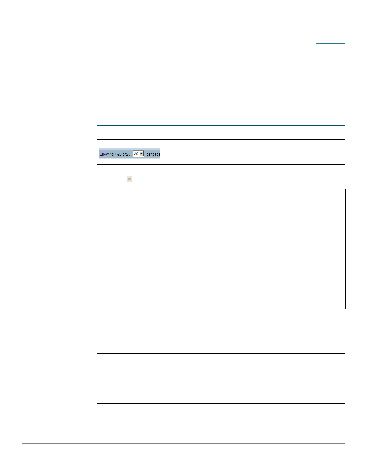
Management Buttons
The following table describes the commonly-used buttons that appear on various
pages in the system.
Management Buttons
Button Name Description
Use the pull-down menu to configure the number of
entries per page.
Indicates a mandatory field.
Add Click to display the related Add page and add an entry to a
table. Enter the information and click Apply to save it to the
Running Configuration. Click Close to return to the main
page. Click Save to display the Copy/Save Configuration
page and save the Running Configuration to the Startup
Configuration file type on the switch.
Apply Click to apply changes to the Running Configuration on the
switch. If the switch is rebooted, the Running Configuration
is lost, unless it is saved to the Startup Configuration file
type or another file type. Click Save to display the Copy/
Save Configuration page and save the Running
Configuration to the Startup Configuration file type on the
switch.
Cancel Click to reset changes made on the page.
Clear All
Interfaces
Counters
Clear Interface
Counters
Clear Logs Clears log files.
Clear Table Clears table entries.
Close Returns to main page. If any changes were not applied to
Click to clear the statistic counters for all interfaces.
Click to clear the statistic counters for the selected
interface.
the Running Configuration, a message is displayed.
Cisco Small Business 200 Series Smart Switch Administration Guide 15
Page 16

Getting Started
Window Navigation
1
Management Buttons (Continued)
Button Name Description
Copy Settings A table typically contains one or more entries containing
configuration settings. Instead of modifying each entry
individually, it is possible to modify one entry and then
copy the selected entry to multiple entries, as described
below:
1. Select the entry to be copied. Click Copy Settings to
display the popup.
2. Enter the destination entry numbers in the to field.
3. Click Apply to save the changes and click Close to
return to the main page.
Delete After selecting an entry in the table, click Delete to
remove.
Details Click to display the details associated with the entry
selected.
Edit Select the entry and click Edit. The Edit page opens, and
the entry can be modified.
1. C li ck Apply to save the changes to the Running
Configuration.
2. Click Close to return to the main page.
Go Enter the query filtering criteria and click Go. The results
are displayed on the page.
Te st Click Te s t to perform the related tests.
Cisco Small Business 200 Series Smart Switch Administration Guide 16
Page 17

Viewing Statistics
This section describes how to view switch statistics.
It covers the following topics:
• Viewing Ethernet Interfaces
• Viewing Etherlike Statistics
• Viewing 802.1X EAP Statistics
• Managing RMON
Viewing Ethernet Interfaces
2
The Interface page displays traffic statistics per port. The refresh rate of the
information can be selected.
This page is useful for analyzing the amount of traffic that is both sent and
received and its dispersion (Unicast, Multicast, and Broadcast).
To display Ethernet statistics and/or set the refresh rate:
STEP 1 Click Status and Statistics > Interface. The Interface page is displayed.
STEP 2 Enter the parameters.
• Interface—Select the type of interface and specific interface for which
Ethernet statistics are to be displayed.
• Refresh Rate—Select the time period that passes before the interface
Ethernet statistics are refreshed. The available options are:
- No Refresh—Statistics are not refreshed.
- 15 Sec—Statistics are refreshed every 15 seconds.
- 30 Sec—Statistics are refreshed every 30 seconds.
Cisco Small Business 200 Series Smart Switch Administration Guide 18
Page 18

Viewing Statistics
Viewing Etherlike Statistics
2
- 60 Sec—Statistics are refreshed every 60 seconds.
The Receive Statistics area displays information about incoming packets.
• Tot al By t es (O c te ts )—Octets received, including bad packets and FCS
octets, but excluding framing bits.
• Unicast Packets—Good Unicast packets received.
• Multicast Packets—Good Multicast packets received.
• Broadcast Packets—Good Broadcast packets received.
• Packets with Errors—Packets with errors received.
The Transmit Statistics area displays information about outgoing packets.
• Tot al By t es (O c te ts )—Octets transmitted, including bad packets and FCS
octets, but excluding framing bits.
• Unicast Packets—Good Unicast packets transmitted.
• Multicast Packets—Good Multicast packets transmitted.
• Broadcast Packets—Good Broadcast packets transmitted.
To clear statistics counters:
• Click Clear Interface Counters to clear counters for the interface displayed.
• Click Clear All Interface Counters to clear counters for all interfaces.
Viewing Etherlike Statistics
The Etherlike page displays statistics per port according to the Etherlike MIB
standard definition. The refresh rate of the information can be selected. This page
provides more detailed information regarding errors in the physical layer (Layer 1),
which might disrupt traffic.
To view Etherlike Statistics and/or set the refresh rate:
STEP 1 Click Status and Statistics > Etherlike. The Etherlike page is displayed.
STEP 2 Enter the parameters.
Cisco Small Business 200 Series Smart Switch Administration Guide 19
Page 19

Viewing Statistics
Viewing 802.1X EAP Statistics
2
• Interface—Select the type of interface and specific interface for which
Ethernet statistics are to be displayed.
• Refresh Rate—Select the amount of time that passes before the Etherlike
statistics are refreshed.
The fields are displayed for the selected interface.
• Frame Check Sequence (FCS) Errors—Received frames that failed the
CRC (cyclic redundancy checks).
• Single Collision Frames—Frames that were involved in a single collision,
but were successfully transmitted.
• Late Collisions—Collisions that have been detected after the first 512 bits
of data.
• Excessive Collisions—Number of transmissions rejected due to excessive
collisions.
• Oversize Packets—Packets greater than 2000 octets received.
• Internal MAC Receive Errors—Frames rejected because of receiver errors.
• Pause Frames Received—Received flow control pause frames.
• Pause Frames Transmitted—Flow control pause frames transmitted from
the selected interface.
To clear statistics counters:
• Click Clear Interface Counters to clear the selected interface’s counters.
• Click Clear All Interface Counters to clear the counters of all interfaces.
Viewing 802.1X EAP Statistics
The 802.1x EAP page displays detailed information regarding the EAP (Extensible
Authentication Protocol) frames that were sent or received. To configure the
802.1X feature, see the 802.1X Properties page.
To view the EAP Statistics and/or set the refresh rate:
Cisco Small Business 200 Series Smart Switch Administration Guide 20
Page 20

Viewing Statistics
Viewing 802.1X EAP Statistics
STEP 1 Click Status and Statistics > 802.1x EAP. The 802.1x EAP page is displayed.
STEP 2 Select the Interface that is polled for statistics.
STEP 3 Select the time period (Refresh Rate) that passes before the EAP statistics are
2
refreshed.
The values are displayed for the selected interface.
• EAPOL Frames Received—Valid EAPOL frames received on the port.
• EAPOL Frames Transmitted—Valid EAPOL frames transmitted by the port.
• EAPOL Start Frames Received—EAPOL Start frames received on the port.
• EAPOL Logoff Frames Received—EAPOL Logoff frames received on the
port.
• EAP Response/ID Frames Received—EAP Resp/ID frames received on the
port.
• EAP Response Frames Received—EAP Response frames received by the
port (other than Resp/ID frames).
• EAP Request/ID Frames Transmitted—EAP Req/ID frames transmitted by
the port.
• EAP Request Frames Transmitted—EAP Request frames transmitted by
the port.
• Invalid EAPOL Frames Received—Unrecognized EAPOL frames received
on this port.
• EAP Length Error Frames Received—EAPOL frames with an invalid Packet
Body Length received on this port.
• Last EAPOL Frame Version—Protocol version number attached to the most
recently received EAPOL frame.
• Last EAPOL Frame Source—Source MAC address attached to the most
recently received EAPOL frame.
To clear statistics counters:
• Click Clear Interface Counters to clear the selected interface’s counters.
• Click Clear All Interface Counters to clear the counters of all interfaces.
Cisco Small Business 200 Series Smart Switch Administration Guide 21
Page 21

Viewing Statistics
Managing RMON
Managing RMON
RMON (Remote Networking Monitoring) enables the switch to proactively monitor
traffic statistics over a given period.
With this feature, you can view the current statistics (since the counter values were
cleared).
Viewing RMON Statistics
The Statistics page displays detailed information regarding packet sizes and
information regarding physical layer errors. The information displayed is according
to the RMON standard. An oversized packet is defined as an Ethernet frame with
the following criteria:
2
• Packet length is greater than MRU byte size.
• Collision event has not been detected.
• Late collision event has not been detected.
• Received (Rx) error event has not been detected.
• Packet has a valid CRC.
To view RMON statistics and/or set the refresh rate:
STEP 1 Click Status and Statistics > RMON > Statistics. The Statistics page is
displayed.
STEP 2 Select the Interface for which Ethernet statistics are to be displayed.
STEP 3 Select the Refresh Rate, the time period that passes before the interface
statistics are refreshed.
The statistics are displayed for the selected interface.
• Bytes Received—Number of octets received, including bad packets and
FCS octets, but excluding framing bits.
• Drop Events—Number of packets dropped.
• Packets Received—Number of good packets received, including Multicast
and Broadcast packets.
• Broadcast Packets Received—Number of good Broadcast packets
received. This number does not include Multicast packets.
Cisco Small Business 200 Series Smart Switch Administration Guide 22
Page 22

Viewing Statistics
Managing RMON
2
• Multicast Packets Received—Number of good Multicast packets received.
• CRC & Align Errors—Number of CRC and Align errors that have occurred.
• Undersize Packets—Number of undersized packets (less than 64 octets)
received.
• Oversize Packets—Number of oversized packets (over 2000 octets)
received.
• Fragments—Number of fragments (packets with less than 64 octets,
excluding framing bits, but including FCS octets) received.
• Jabbers—Total number received packets that were longer than 1632
octets. This number excludes frame bits, but includes FCS octets that had
either a bad FCS (Frame Check Sequence) with an integral number of octets
(FCS Error) or a bad FCS with a non-integral octet (Alignment Error) number.
A Jabber packet is defined as an Ethernet frame that satisfies the following
criteria:
- Packet data length is greater than MRU.
- Packet has an invalid CRC.
- Received (Rx) Error Event has not been detected.
• Collisions—Number of collisions received. If Jumbo Frames are enabled,
the threshold of Jabber Frames is raised to the maximum size of Jumbo
Frames.
• Frames of 64 Bytes—Number of frames, containing 64 bytes that were
received.
• Frames of 65 to 127 Bytes—Number of frames, containing 65-127 bytes
that were received.
• Frames of 128 to 255 Bytes—Number of frames, containing 128-255 bytes
that were received.
• Frames of 256 to 511 Bytes—Number of frames, containing 256-511 bytes
that were received.
• Frames of 512 to 1023 Bytes—Number of frames, containing 512-1023
bytes that were received.
• Frames greater than 1024 Bytes—Number of frames, containing 1024-
2000 bytes, and Jumbo Frames, that were received.
Cisco Small Business 200 Series Smart Switch Administration Guide 23
Page 23

Viewing Statistics
Managing RMON
2
To clear statistics counters:
• Click Clear Interface Counters to clear the selected interface’s counters.
• Click Clear All Interface Counters to clear the counters of all interfaces.
Cisco Small Business 200 Series Smart Switch Administration Guide 24
Page 24

Managing System Logs
This section describes the System Log feature, which enables the switch to
generate several independent logs. Each log is a set of messages describing
system events.
The switch generates the following local logs:
• Log sent to the console interface.
• Log written into a cyclical list of logged events in the RAM and erased when
the switch reboots.
• Log written to a cyclical log-file saved to the Flash memory and persists
across reboots.
3
In addition, you can send messages to remote SYSLOG servers in the form of
SYSLOG messages.
This section covers the following sections:
• Setting System Log Settings
• Setting Remote Logging Settings
• Viewing Memory Logs
Setting System Log Settings
You can enable or disable logging on the Log Settings page, and select whether
to aggregate log messages.
You can select the events by severity level. Each log message has a severity level
marked with the first letter of the severity level concatenated with a dash (-) on
each side (except for Emergency that is indicated by the letter F). For example, the
log message "%INIT-I-InitCompleted: … " has a severity level of I, meaning
Informational.
Cisco Small Business 200 Series Smart Switch Administration Guide 25
Page 25

Managing System Logs
Setting System Log Settings
3
The event severity levels are listed from the highest severity to the lowest severity,
as follows:
• Emergency—System is not usable.
• Alert—Action is needed.
• Critical—System is in a critical condition.
• Error—System is in error condition.
• Warning—System warning has occurred.
• Notice—System is functioning properly, but a system notice has occurred.
• Informational—Device information.
• Debug—Detailed information about an event.
You can select different severity levels for RAM and Flash logs. These logs are
displayed in the RAM Memory page and Flash Memory page, respectively.
Selecting a severity level to be stored in a log causes all of the higher severity
events to be automatically stored in the log. Lower severity events are not stored
in the log.
For example, if Warning is selected, all severity levels that are Warning and higher
are stored in the log (Emergency, Alert, Critical, Error, and Warning). No events with
severity level below Warning are stored (Notice, Informational, and Debug).
To set global log parameters:
STEP 1 Click Administration > System Log > Log Settings. The Log Settings page
opens.
STEP 2 Enter the parameters.
• Logging—Select to enable message logging.
• Syslog Aggregator—Select to enable the aggregation of SYSLOG
messages and traps. If enabled, identical and contiguous SYSLOG
messages and traps are aggregated over the specified Max Aggregation
Time and sent in a single message. The aggregated messages are sent in
the order of their arrival. Each message states the number of times it was
aggregated.
• Max Aggregation Time—Enter the interval of time that SYSLOG messages
are aggregated.
Cisco Small Business 200 Series Smart Switch Administration Guide 26
Page 26

Managing System Logs
Setting Remote Logging Settings
• RAM Memory Logging—Select the severity levels of the messages to be
logged to the RAM.
• Flash Memory Logging—Select the severity levels of the messages to be
logged to the Flash memory.
STEP 3 Click Apply. The Running Configuration file is updated.
Setting Remote Logging Settings
The
Remote Log Servers
log messages are sent (using the SYSLOG protocol). For each server, you can
configure the severity of the messages that it receives.
page enables defining remote SYSLOG servers where
3
To d e fi ne S Y S L O G se r ve rs :
STEP 1 Click Administration > System Log > Remote Log Servers. The
Servers
This page displays the list of remote log servers.
STEP 2 Click Add. The
STEP 3 Enter the parameters.
page opens.
Add Remote Log Server
• Server Definition—Select whether to identify the remote log server by IP
address or name.
• IP Version—Select the supported IP format.
• IPv6 Address Type—Select the IPv6 address type (if IPv6 is used). The
options are:
- Link Local—The IPv6 address uniquely identifies hosts on a single
network link. A link local address has a prefix of FE80, is not routable, and
can be used for communication only on the local network. Only one link
local address is supported. If a link local address exists on the interface,
this entry replaces the address in the configuration.
page opens.
Remote Log
- Global—The IPv6 address is a global Unicast IPV6 type that is visible and
• Link Local Interface—Select the link local interface (if IPv6 Address Type
Link Local is selected) from the list.
Cisco Small Business 200 Series Smart Switch Administration Guide 27
reachable from other networks.
Page 27

Managing System Logs
Viewing Memor y Logs
3
• Log Server IP Address/Name—Enter the IP address or domain name of the
log server.
• UDP Port—Enter the UDP port to which the log messages are sent.
• Facility—Select a facility value from which system logs are sent to the
remote server. Only one facility value can be assigned to a server. If a second
facility code is assigned, the first facility value is overridden.
• Description—Enter a server description.
• Minimum Severity—Select the minimum level of system log messages to
be sent to the server.
STEP 4 Click Apply. The Add Remote Log Server page
added, and the Running Configuration file is updated.
Viewing Memory Logs
The switch can write to the following logs:
• Log in RAM (cleared during reboot).
• Log in Flash memory (cleared only upon user command).
You can configure the messages that are written to each log by severity, and a
message can go to more than one log, including logs that reside on external
SYSLOG servers.
RAM Memory
The RAM Memory page displays all messages that were saved in the RAM
(cache) in chronological order. Entries are stored in the RAM log according to the
configuration in the Log Settings page.
closes, the SYSLOG server is
To view log entries, click Status and Statistics > View Log > RAM Memory. The
RAM Memory page
The top of the page has a button that allows you to Disable Alert Icon Blinking.
Click to toggle between disable and enable.
This page displays the following fields:
Cisco Small Business 200 Series Smart Switch Administration Guide 28
opens.
Page 28

Managing System Logs
Viewing Memor y Logs
3
• Log Index—Log entry number.
• Log Time—Time when message was generated.
• Severity—Event severity.
• Description—Message text describing the event.
To clear the log messages, click Clear Logs. The messages are cleared.
Flash Memory
The Flash Memory page displays the messages that were stored in the Flash
memory, in chronological order. The minimum severity for logging is configured in
the Log Settings page. Flash logs remain when the switch is rebooted. You can
clear the logs manually.
To view the Flash logs, click Status and Statistics > View Log > Flash Memory.
The
Flash Memory
This page displays the following fields:
• Log Index—Log entry number.
• Log Time—Time when message was generated.
• Severity—Event severity.
• Description—Message text describing the event.
To clear the messages, click Clear Logs. The messages are cleared.
page opens.
Cisco Small Business 200 Series Smart Switch Administration Guide 29
Page 29

Managing System Files
This section describes how system files are managed.
The following topics are covered:
• Types of System Files
• Upgrade/Backup Firmware/Language
• Downloading or Backing-up a Configuration or Log
• Viewing Configuration Files Properties
• Copying Configuration Files
• DHCP Auto Configuration
4
Types of System Files
System files are files that contain configuration information, firmware images or
boot code.
Various actions can be performed with these files, such as: selecting the firmware
file from which the switch boots, copying various types of configuration files
internally on the switch, or copying files to or from an external device, such as an
external server.
The possible methods of file transfer are:
• Internal copy.
• HTTP/HTTPS that uses the facilities that the browser provides.
• TFTP client, requiring a TFTP server.
Configuration files on the switch are defined by their type, and contain the settings
and parameter values for the device.
Cisco Small Business 200 Series Smart Switch Administration Guide 30
Page 30

Managing System Files
Ty p es of Sy s te m Fi le s
4
When a configuration is referenced on the switch, it is referenced by its
configuration file type (such as Startup Configuration or Running Configuration),
as opposed to a file name that can be modified by the user.
Content can be copied from one configuration file type to another, but the names
of the file types cannot be changed by the user.
Other files on the device include firmware, boot code, and log files, and are
referred to as operational files.
The configuration files are text files and can be edited in a text editor, such as
Notepad after they are copied to an external device, such as a PC.
Files and File Types
The following types of configuration and operational files are found on the switch:
• Running Configuration—Contains the parameters currently being used by
the switch to operate. This is the only file type that is modified when you
change parameter values on the device.
If the switch is rebooted, the Running Configuration is lost. The Startup
Configuration, stored in Flash, overwrites the Running Configuration, stored
in RAM.
To preserve any changes you made to the switch, you must save the
Running Configuration to the Startup Configuration, or another file type.
• Startup Configuration—The parameter values that were saved by copying
another configuration (usually the Running Configuration) to the Startup
Configuration.
The Startup Configuration is retained in Flash and is preserved when the
switch is rebooted. At this time, the Startup Configuration is copied to RAM
and identified as the Running Configuration.
• Mirror Configuration—A copy of the Startup Configuration, created by the
switch when the following conditions exist:
- The switch has been operating continuously for 24 hours.
- No configuration changes have been made to the Running Configuration
in the previous 24 hours.
- The Startup Configuration is identical to the Running Configuration.
Only the system can copy the Startup Configuration to the Mirror
Configuration. However, you can copy from the Mirror Configuration to other
file types or to another device.
Cisco Small Business 200 Series Smart Switch Administration Guide 31
Page 31

Managing System Files
Ty p es of Sy s te m Fi le s
4
The option of automatically copying the Running Configuration to the mirror
configuration can be disabled in the Configuration Files Properties page.
• Backup Configuration—A manual copy of a configuration file used for
protection against system shutdown or for the maintenance of a specific
operating state. You can copy the Mirror Configuration, Startup
Configuration, or Running Configuration to a Backup Configuration file. The
Backup Configuration exists in Flash and is preserved if the device is
rebooted.
• Firmware—The program that controls the operations and functionality of
the switch. More commonly referred to as the image.
• Boot Code—Controls the basic system startup and launches the firmware
image.
• Language File—The dictionary that enables the web-based configuration
utility windows to be displayed in the selected language.
• Flash Log—SYSLOG messages stored in Flash memory.
File Actions
The following actions can be performed to manage firmware and configuration
files:
• Upgrade the firmware or boot code, or replace a second language, as
described in Upgrade/Backup Firmware/Language section.
• Save configuration files on the switch to a location on another device as
described in the Downloading or Backing-up a Configuration or Log
section.
• Clear the Startup Configuration or Backup Configuration file types as
described in the Viewing Configuration Files Properties section.
• Copy one configuration file type to another configuration file type as
described in the Copying Configuration Files section.
• Enable automatically uploading a configuration file from a DHCP server to
the switch, as described in the DHCP Auto Configuration section.
This section covers the following topics:
• Upgrade/Backup Firmware/Language
• Downloading or Backing-up a Configuration or Log
• Viewing Configuration Files Properties
Cisco Small Business 200 Series Smart Switch Administration Guide 32
Page 32

Managing System Files
Upgrade/Backup Firmware/Language
• Copying Configuration Files
• DHCP Auto Configuration
Upgrade/Backup Firmware/Language
The Upgrade/Backup Firmware/Language process can be used to:
• Upgrade or backup the firmware image.
• Upgrade or backup the boot code.
• Import or upgrade a second language file.
The following methods for transferring files are supported:
4
• HTTP/HTTPS that uses the facilities provided by the browser
• TFTP that requires a TFTP server
If a new language file was loaded onto the switch, the new language can be
selected from the drop-down menu. (It is not necessary to reboot the switch).
A single firmware image is stored on the switch. After new firmware has been
successfully loaded into the switch, the device needs to be rebooted prior to the
new firmware taking effect. The
image prior to the reboot.
Summary
page continues to show the previous
Upgrading/Backing Up Firmware or Language File
To upgrade or backup a software image or language file:
STEP 1 Click Administration > File Management > Upgrade/Backup Firmware/
Language. The Upgrade/Backup Firmware/Language page opens.
STEP 2 Click the Transfer Method. Proceed as follows:
• If you selected TFTP, go to STEP 3.
• If you selected via HTTP/HTTPS, go to STEP 4.
STEP 3 If you selected via TFTP, enter the parameters as described in this step.
Otherwise, skip to STEP 4.
Cisco Small Business 200 Series Smart Switch Administration Guide 33
Page 33

Managing System Files
Upgrade/Backup Firmware/Language
Select one of the following actions:
• Upgrade Save Action—Specifies that the file type on the switch is to be
replaced with a new version of that file type located on a TFTP server.
• Backup Save Action—Specifies that a copy of the file type is to be saved to
a file on another device.
Enter the following fields:
• File Type—Select the destination file type. Only valid file types are shown.
(The file types are described in the Files and File Types section).
• TFTP Server Definition—Select whether to specify the TFTP server by IP
address or domain name.
• IP Version—Select whether an IPv4 or an IPv6 address is used.
• IPv6 Address Type—Select the IPv6 address type (if IPv6 is used). The
options are:
4
- Link Local—The IPv6 address uniquely identifies hosts on a single
network link. A link local address has a prefix of FE80, is not routable, and
can be used for communication only on the local network. Only one link
local address is supported. If a link local address exists on the interface,
this entry replaces the address in the configuration.
- Global—The IPv6 address is a global Unicast IPV6 type that is visible and
reachable from other networks.
• Link Local Interface—Select the link local interface (if IPv6 is used) from the
list.
• TFTP Server IP Address/Name—Enter the IP address or the domain name
of the TFTP server.
• (For Upgrade) Source File Name—Enter the name of the source file.
• (For Backup) Destination File Name—Enter the name of the backup file.
STEP 4 If you selected via HTTP/HTTPS, you can only Upgrade. Enter the parameters as
described in this step.
• File Type—Select the configuration file type. Only valid file types can be
selected. (The file types are described in the Files and File Types section).
The following file types can be upgraded:
- Firmware Image—Select this to upgrade the firmware image.
- Language—Select this to upgrade the language file.
Cisco Small Business 200 Series Smart Switch Administration Guide 34
Page 34

Managing System Files
Downloading or Backing-up a Configuration or Log
• File Name—Click Browse to select a file or enter the path and source file
name to be used in the transfer.
STEP 5 Click Apply or Done. The file is upgraded or backed up.
Downloading or Backing-up a Configuration or Log
The
Download/Backup Configuration/Log
• Backing up configuration files or logs from to switch to an external device.
• Restoring configuration files from an external device to the switch.
NOTE
page enables
4
When restoring a configuration file to the Running Configuration, the imported file
adds any configuration commands that did not exist in the old file and overwrites
any parameter values in the existing configuration commands.
When restoring a configuration file to the Startup Configuration or a backup
configuration file, the new file replaces the previous file.
When restoring to Startup Configuration, the switch must be rebooted for the
restored Startup Configuration to be used as the Running Configuration. You can
reboot the switch by using the process described in the Rebooting the Switch
section.
To backup or restore the system configuration file:
STEP 1 Click Administration > File Management > Download/Backup Configuration/
Log. The Download/Backup Configuration/Log page opens.
STEP 2 Select the Transfer Method.
STEP 3 If you selected via TFTP, enter the parameters. Otherwise, skip to STEP 4.
Cisco Small Business 200 Series Smart Switch Administration Guide 35
Page 35

Managing System Files
Downloading or Backing-up a Configuration or Log
Select either Download or Backup as the Save Action.
Download Save Action—Specifies that the file on another device replaces a file
type on the switch. Enter the following fields:
a. Server Definition—Select whether to specify the TFTP server by IP address
or by domain name.
b. IP Version—Select whether an IPv4 or an IPv6 address is used.
NOTE If the server is selected by name in the Server Definition, there is no
need to select the IP Version related options.
c. IPv6 Address Type—Select the IPv6 address type (if used). The options are:
- Link Local—The IPv6 address uniquely identifies hosts on a single
network link. A link local address has a prefix of FE80, is not routable, and
can be used for communication only on the local network. Only one link
local address is supported. If a link local address exists on the interface,
this entry replaces the address in the configuration.
4
- Global—The IPv6 address is a global Unicast IPV6 type that is visible and
reachable from other networks.
d. Link-Local Interface—Select the link local interface from the list.
e. TFTP Server—Enter the IP address of the TFTP server.
f. Source File Name—Enter the source file name. File names cannot contain
slashes (\ or /), cannot start with a period (.), and must include between 1 and
160 characters. (Valid characters: A-Z, a-z, 0-9, “.”, “-”, “_”).
g. Destination File Type—Enter the destination configuration file type. Only valid
file types are displayed. (The file types are described in the Files and File
Types section).
Backup Save Action—Specifies that a file type is to be copied to a file on another
device. Enter the following fields:
a. Server Definition—Select whether to specify the TFTP server by IP address
or by domain name.
b. IP Version—Select whether an IPv4 or an IPv6 address is used.
c. IPv6 Address Type—Select the IPv6 address type (if used). The options are:
Cisco Small Business 200 Series Smart Switch Administration Guide 36
Page 36

Managing System Files
Downloading or Backing-up a Configuration or Log
• Link Local—The IPv6 address uniquely identifies hosts on a single network
link. A link local address has a prefix of FE80, is not routable, and can be used
for communication only on the local network. Only one link local address is
supported. If a link local address exists on the interface, this entry replaces
the address in the configuration.
• Global—The IPv6 address is a global Unicast IPV6 type that is visible and
reachable from other networks.
d. Link-Local Interface—Select the link local interface from the list.
e. TFTP Server IP Address/Name—Enter the IP address or domain name of the
TFTP server.
f. Source File Type—Enter the source configuration file type. Only valid file
types are displayed. (The file types are described in the Files and File Types
section).
4
g. Sensitive Data—Select how sensitive data should be included in the backup
file. The following options are available:
- Exclude—Do not include sensitive data in the backup.
- Encrypted—Include sensitive data in the backup in its encrypted form.
- Plaintext—Include sensitive data in the backup in its plaintext form.
NOTE The available sensitive data options are determined by the current
user SSD rules. For details, refer to Secure Sensitive Data Management >
SSD Rules page.
h. Destination File Name—Enter the destination file name. File names cannot
contain slashes (\ or /), the leading letter of the file name must not be a period
(.), and the file name must be between 1 and 160 characters. (Valid characters:
A-Z, a-z, 0-9, “.”, “-”, “_”).
i. Click Apply. The file is upgraded or backed up.
STEP 4 If you selected via HTTP/HTTPS, enter the parameters as described in this step.
Cisco Small Business 200 Series Smart Switch Administration Guide 37
Page 37

Managing System Files
Viewing Configuration Files Properties
Select the Save Action.
If Save Action is Download (replacing the file on the switch with a new version
from another device), do the following. Otherwise, go to the next procedure in this
step.
a. Source File Name—Click Browse to select a file or enter the path and source
file name to be used in the transfer.
b. Destination File Type—Select the configuration file type. Only valid file types
are displayed. (The file types are described in the Files and File Types
section).
c. Click Apply. The file is transferred from the other device to the switch.
If Save Action is Backup (copying a file to another device), do the following:
a. Source File Type—Select the configuration file type. Only valid file types are
displayed. (The file types are described in the Files and File Types section).
4
b. Sensitive Data—Select how sensitive data should be included in the backup
file. The following options are available:
- Exclude—Do not include sensitive data in the backup.
- Encrypted—Include sensitive data in the backup in its encrypted form.
- Plaintext—Include sensitive data in the backup in its plaintext form.
NOTE The available sensitive data options are determined by the current
user SSD rules. For details, refer to Secure Sensitive Data Management >
SSD Rules page.
c. Click Apply. The file is upgraded or backed up.
Viewing Configuration Files Properties
The
Configuration Files Properties
configuration files were created. It also enables deleting the Startup Configuration
and Backup Configuration files. You cannot delete the other configuration file
types.
page allows you to see when various system
Cisco Small Business 200 Series Smart Switch Administration Guide 38
Page 38

Managing System Files
Copying Configuration Files
STEP 1 Click Administration > File Management > Configuration Files Properties. The
STEP 2 If required, disable Auto Mirror Configuration. This disables the automatic
STEP 3 If required, select either the Startup Configuration, Backup Configuration or both
4
To set whether mirror configuration files will be created, clear configuration files
and see when configuration files were created:
Configuration Files Properties
creation of mirror configuration files. When disabling this feature, the mirror
configuration file, if it exists, is deleted. See Types of System Files for a
description of mirror files and why you might not want to automatically create
mirror configuration files.
and click Clear Files to delete these files.
This page provides the following fields:
page opens.
• Configuration File Name—Displays the type of file.
• Creation Time—Displays the date and time that file was modified.
Copying Configuration Files
When you click Apply on any window, changes that you made to the switch
configuration settings are stored only in the Running Configuration. To preserve
the parameters in the Running Configuration, the Running Configuration must be
copied to another configuration type or saved on another device.
CAUTION Unless the Running Configuration is copied to the Startup Configuration or another
configuration file, all changes made since the last time the file was copied are lost
when the switch is rebooted.
The following combinations of copying internal file types are allowed:
• From the Running Configuration to the Startup Configuration or Backup
Configuration.
• From the Startup Configuration to the Backup Configuration.
• From the Backup Configuration to the Startup Configuration.
• From the Mirror Configuration to the Startup Configuration or Backup
Configuration.
Cisco Small Business 200 Series Smart Switch Administration Guide 39
Page 39

Managing System Files
DHCP Auto Configuration
4
To copy one type of configuration file to another type of configuration file:
STEP 1 Click Administration > File Management > Copy/Save Configuration. The
Save Configuration
STEP 2 Select the Source File Name to be copied. Only valid file types are displayed
(described in the Files and File Types section).
STEP 3 Select the Destination File Name to be overwritten by the source file.
• If you are backing up a configuration file, select one of the following formats
for the backup file.
- Exclude—Sensitive data is not included in the backup file.
- Encrypted—Sensitive data is included in the backup file in encrypted
form.
- Plaintext—Sensitive data is included in the backup file in plain text.
NOTE The available sensitive data options are determined by the current
user SSD rules. For details, refer to Secure Sensitive Data Management >
SSD Rules page.
STEP 4 The Save Icon Blinking field indicates whether an icon blinks when there is
unsaved data. To disable/enable this feature, click Disable/Enable Save Icon
Blinking.
page opens.
Copy/
STEP 5 Click Apply. The file is copied.
DHCP Auto Configuration
The switch supports DHCP auto configuration, which provides a means of passing
configuration information (including the IP address of a TFTP server and a file
name) to hosts on a TCP/IP network. Based on this protocol, the Auto
Configuration feature enables a switch to download configuration files from a
TFTP server.
By default, the switch is enabled as a DHCP client when the Auto Configuration
feature is enabled.
Cisco Small Business 200 Series Smart Switch Administration Guide 40
Page 40

Managing System Files
DHCP Auto Configuration
4
Triggering DHCP Auto Configuration
The Auto Configuration process is triggered in the following cases:
• After reboot when an IP address is allocated or renewed dynamically (using
DHCP).
• Upon an explicit DHCP renewal request and if the switch and the server are
configured to do so.
• Upon automatic renewal of the DHCP lease.
Server Name/Address
You can specify the IP address or the name of the TFTP server. This server is used
if no server IP address was specified in the DHCP message. This DHCP message
is the DHCP offer message coming from the DHCP server. Possible options are
bootp options sname and siaddr and DHCP option 150 or option 66. This is an
optional parameter.
Backup Configuration File Name
You can specify the backup configuration filename. This file is used if no filename
was specified in the DHCP message. This is an optional parameter.
Auto Configuration Process
When the Auto Configuration process is triggered, the following sequence of
events occurs:
• The DHCP server is accessed to acquire the TFTP server IP address and
configuration file name. These parameters are passed in the DHCP option
parameters.
• If an IP address was not supplied by the DHCP server, the backup server
address is used (if configured by the user).
• If the IP address was not supplied by the DHCP server and the backup
TFTP server address parameter is empty then the Auto Configuration
process is halted.
NOTE In the previous two bullets, the IP address refers to the IP address or
hostname of the TFTP server.
Cisco Small Business 200 Series Smart Switch Administration Guide 41
Page 41

Managing System Files
DHCP Auto Configuration
4
• If the configuration filename was supplied by the DHCP server, then the
copy protocol (TFTP) is selected as described in DHCP Auto
Configuration.
• If a configuration filename was not supplied by the DHCP server, the
backup configuration file name is used.
• If the configuration filename was not supplied by the DHCP server and the
backup configuration file name is empty, the Auto Configuration process is
halted.
• The TFTP server is accessed to download the file from it.
The download process is done only if the new configuration filename is
different from the current configuration filename (even if the current
configuration file is empty).
• A SYSLOG message is generated acknowledging that the Auto
Configuration process is completed.
Configuring DHCP Auto Configuration
The
DHCP Auto Configuration
the information is not provided in a DHCP message:
• Enable DHCP auto configuration feature.
• Specify the download protocol.
• Configure the switch to receive configuration information from a specific file
on a specific server.
Note the following regarding the DHCP auto configuration process:
• A configuration file that is placed on the TFTP server must match the form
and format requirements of a supported configuration file. The form and
format of the file are checked, but the validity of the configuration
parameters is not checked prior to loading it to the Startup Configuration.
• To ensure that the device configuration functions as intended, due to
allocation of different IP addresses with each DHCP renew cycle, it is
recommended that IP addresses be bound to MAC addresses in the DHCP
server table. This ensures that each device has its own reserved IP address
and other relevant information.
page is used to perform the following actions when
Cisco Small Business 200 Series Smart Switch Administration Guide 42
Page 42

Managing System Files
DHCP Auto Configuration
4
To configure DHCP server auto configuration:
STEP 1 Click Administration > File Management > DHCP Auto Configuration. The
Auto Configuration
STEP 2 Enter the values.
• Auto Configuration Via DHCP—Select this field to enable DHCP Auto
Configuration.
• Backup Server Definition—Select By IP Address or By name to configure
the TFTP server.
STEP 3 Enter the following optional information to be used if DHCP Auto Configuration is
not enabled, or if it is enabled, but no configuration file was received from the
DHCP server.
• Backup Server IP Address/Name—Enter the IP address or the name of the
server to be used if no server IP address was specified in the DHCP
message.
• Backup Configuration File Name—Enter the path and file name of the file to
be used if no configuration file name was specified in the DHCP message.
The window displays the following:
page opens.
DHCP
• Last Auto Configuration Server IP Address—Displays the IP address of
the TFTP server last used to perform auto configuration.
• Last Auto Configuration File Name—Displays the last file name used by the
switch in auto configuration.
NOTE The Last Auto Configuration File Name is compared with the
information received from a DHCP server when an IP address is received for
the switch. If this value does not match, the switch transfers the configuration
file from the server identified by the DHCP server into the Startup
Configuration file, and initiates a reboot. If the values match, no action is
taken.
STEP 4 Click Apply. The DHCP Auto Configuration feature is updated in the Running
Configuration.
Cisco Small Business 200 Series Smart Switch Administration Guide 43
Page 43

General Administrative Information
This section describes how to view system information and configure various
options on the switch.
It covers the following topics:
• Switch Models
• System Information
• Rebooting the Switch
• Monitoring the Fan Status and Temperature
• Defining Idle Session Timeout
5
Switch Models
NOTE The following port conventions are used:
• Pinging a Host
All models can be fully managed through the web-based switch configuration
utility.
In Layer 2 system mode, the switch forwards packets as a VLAN-aware bridge. In
Layer 3 system mode, the switch performs both IPv4 routing and VLAN-aware
bridging.
• GE is used for Gigabit Ethernet (10/100/1000) ports.
• FE is used for Fast Ethernet (10/100) ports.
• .
The following table describes the various models, the number and type of ports
they contain and their Power over Ethernet (PoE) information.
Cisco Small Business 200 Series Smart Switch Administration Guide 44
Page 44

General Administrative Information
Switch Models
Smart Switch Models
5
Model Name Product ID
(PID)
SG200-18 SLM2016T 16 GE ports + 2 GE special-purpose
SG200-26 SLM2024T 24 GE ports + 2 GE special-purpose
SG200-26P SLM2024PT 24 GE ports + 2 GE special-purpose
SG200-50 SLM2048T 48 GE ports + 2 GE special-purpose
SG200-50P SLM2048PT 48 GE ports + 2 GE special-purpose
SF200-24 SLM224GT 24 FE ports + 2 GE special-purpose
Description of Ports on Device Power
combo ports
combo-ports
combo-ports
combo-ports
combo-ports
combo-ports
No. of Ports
Dedicated
to PoE
100W 12 ports
180W 24 ports
that Support
PoE
FE1-FE6, FE13
- FE18
FE1-FE12,
FE25 - FE36
SF200-24P SLM224PT 24 FE ports + 2 GE special-purpose
combo-ports
SF200-48 SLM248GT 48 FE ports + 2 GE special-purpose
combo-ports
SF200-48P SLM248PT FE1-FE48, GE1-GE4. 48 FE ports + 2 GE
special-purpose combo-ports
Cisco Small Business 200 Series Smart Switch Administration Guide 45
100W 12 ports
FE1- FE6,
FE13 - FE18
180W 24 ports
FE1- FE12,
FE25 - FE36
Page 45

General Administrative Information
System Information
System Information
The System Summary page provides a graphic view of the switch, and displays
switch status, hardware information, firmware version information, general PoE
status, and other items.
Displaying the System Summary
To view system information, click Status and Statistics > System Summary. The
System Summary page opens.
The
System Summary
System Information:
• System Description—A description of the system.
5
page displays system and hardware information.
• System Location—Physical location of the switch. Click Edit to go the
System Settings page to enter this information.
• System Contact—Name of a contact person. Click Edit to go the System
Settings page to enter this information.
• Host Name—Name of the switch. Click Edit to go the System Settings
page to enter this information. By default, the switch hostname is composed
of the word switch concatenated with the three least significant bytes of the
switch MAC address (the six furthest right hexadecimal digits).
• System Uptime—Time that has elapsed since the last reboot.
• Current Time—Current system time.
• Base MAC Address—Switch MAC address.
• Jumbo Frames—Jumbo frame support status. This support can be
enabled or disabled by using the Port Settings page of the Port
Management menu.
NOTE Jumbo frames support takes effect only after it is enabled, and after
the switch is rebooted.
TCP/UDP Services Status:
• HTTP Service—Displays whether HTTP is enabled/disabled.
• HTTPS Service—Displays whether HTTPS is enabled/disabled.
Cisco Small Business 200 Series Smart Switch Administration Guide 46
Page 46

General Administrative Information
System Information
• Model Description—Switch model description.
• Serial Number—Serial number.
• PID VID—Part number and version ID.
PoE Power Information on Master Unit:
• Maximum Available PoE Power (W)—Maximum available power that can
be delivered by the PoE.
• Total PoE Power Consumption (W)—Total PoE power delivered to
connected PoE devices.
• PoE Power Mode—Port Limit or Class Limit.
Configuring the System Settings
5
To enter system settings:
STEP 1 Click Administration > System Settings. The System Settings page opens.
STEP 2 View or modify the system settings.
• System Description—Displays a description of the switch.
• System Location—Enter the location where the switch is physically located.
• System Contact—Enter the name of a contact person.
• Host Name—Select the host name of this switch. This is used in the prompt
of CLI commands:
- Use Default—The default hostname (System Name) of these switches is:
switch123456, where 123456 represents the last three bytes of the
switch MAC address in hex format.
- User Defined—Enter the hostname. Use only letters, digits, and hyphens.
Host names cannot begin or end with a hyphen. No other symbols,
punctuation characters, or blank spaces are permitted (as specified in
RFC1033, 1034, 1035).
• Custom Login Screen Settings—To display text on the
the text in the Login Banner text box. Click Preview to view the results.
NOTE When you define a login banner from the web-based configuration
utility, it also activates the banner for the CLI interfaces (Console, Telnet, and
SSH).
Cisco Small Business 200 Series Smart Switch Administration Guide 47
Login
page, enter
Page 47

General Administrative Information
Rebooting the Switch
STEP 3 Click Apply to set the values in the Running Configuration file.
Rebooting the Switch
Some configuration changes, such as enabling jumbo frame support, require the
system to be rebooted before they take effect. However, rebooting the switch
deletes the Running Configuration, so it is critical that the Running Configuration is
saved to the Startup Configuration before the switch is rebooted. Clicking Apply
does not save the configuration to the Startup Configuration. For more information
on files and file types, see the Files and File Types section in the Managing
System Files section.
5
You can back up the configuration by using
Copy/Save Configuration
upload the configuration from a remote device. See the Downloading or
Backing-up a Configuration or Log section in the Managing System Files
section.
To reboot the switch:
STEP 1 Click Administration > Reboot. The Reboot page
STEP 2 Click one of the Reboot buttons to reboot the switch.
• Clear Startup Configuration File—Check to clear the configuration on the
switch for the next time it boots up.
• Reboot—Reboots the switch. Since any unsaved information in the Running
Configuration is discarded when the switch is rebooted, you must click Save
in the upper-right corner of any window to preserve current configuration
across the boot process. If the Save option is not displayed, the Running
Configuration matches the Startup Configuration and no action is necessary.
• Reboot to Factory Defaults—Reboots the switch by using the factory
default configuration. This process erases the Startup Configuration file, and
the backup configuration file. Any settings that are not saved to another file
are cleared when this action is selected. The mirror configuration file is not
deleted when restoring to factory default.
or clicking Save at the top of the window. You can also
Administration > File Management >
opens.
NOTE Clearing the Startup Configuration File and Rebooting is not the same
as Rebooting to Factory Defaults. Rebooting to Factory Defaults is more
intrusive.
Cisco Small Business 200 Series Smart Switch Administration Guide 48
Page 48

General Administrative Information
Monitoring the Fan Status and Temperature
Monitoring the Fan Status and Temperature
The Health page displays the switch fan status and temperature on all devices
with fans.
To view the switch health parameters, click Status and Statistics > Health. The
Health
page opens.
5
Health
The
• Fan Status—Fan status. The following values are possible:
• Temperature (in Celsius and Fahrenheit)—The internal temperature of the
• Alarm Temperature (in Celsius and Fahrenheit)—The internal temperature
page displays the following fields:
- OK—Fan is operating normally.
- Fail—Fan is not operating correctly.
- N/A—Fan ID is not applicable for the specific model.
switch (for devices with temperature sensors).
of the unit (for relevant devices) that triggers an alarm.
Defining Idle Session Timeout
The
Idle Session Timeout
session can remain idle before it times out and you must log in again to reestablish
the session.
configures the time interval during which the HTTP
• HTTP Session Timeout
• HTTPS Session Timeout
To set the idle session timeout of an HTTP or HTTPS session:
STEP 1 Click Administration > Idle Session Timeout. The
opens.
STEP 2 Select the timeout for the each session from the corresponding list. The default
timeout value is 10 minutes.
Cisco Small Business 200 Series Smart Switch Administration Guide 49
Idle Session Timeout
page
Page 49

General Administrative Information
Pinging a Host
STEP 3 Click Apply to set the configuration settings on the switch.
Pinging a Host
Ping is a utility used to test if a remote host can be reached and to measure the
round-trip time for packets sent from the switch to a destination device.
Ping operates by sending Internet Control Message Protocol (ICMP) echo request
packets to the target host and waiting for an ICMP response, sometimes called a
pong. It measures the round-trip time and records any packet loss.
To ping a host:
5
STEP 1 Click Administration > Ping. The Ping page
STEP 2 Configure ping by entering the fields:
• Host Definition—Select whether to specify hosts by their IP address or
name.
• IP Version—If the host is identified by its IP address, select either IPv4 or
IPv6 to indicate that it will be entered in the selected format.
• IPv6 Address Type—Select Link Local or Global as the type of IPv6
address to enter.
- Link Local—The IPv6 address uniquely identifies hosts on a single
network link. A link local address has a prefix of FE80, is not routable, and
can be used for communication only on the local network. Only one link
local address is supported. If a link local address exists on the interface,
this entry replaces the address in the configuration.
- Global—The IPv6 address is a global Unicast IPV6 type that is visible and
reachable from other networks.
• Link Local Interface—If the IPv6 address type is Link Local, select from
where it is received.
opens.
• Host IP Address/Name—Address or host name of the device to be pinged.
Whether this is an IP address or host name depends on the Host Definition.
Cisco Small Business 200 Series Smart Switch Administration Guide 50
Page 50

General Administrative Information
Pinging a Host
• Ping Interval—Length of time the system waits between ping packets. Ping
is repeated the number of times configured in the "Number of Pings" field,
whether the ping succeeds or not. Choose to use the default interval or
specify your own value.
• Number of Pings—The number of times the ping operation is performed.
Choose to use the default or specify your own value.
• Status—Displays whether the ping succeeded or failed.
STEP 3 Click Activate Ping to ping the host. The ping status is displayed and another
message is added to the list of messages, indicating the result of the ping
operation.
STEP 4 View the results of ping in the Ping Counters and Status section of the page.
5
Cisco Small Business 200 Series Smart Switch Administration Guide 51
Page 51

System Time
Synchronized system clocks provide a frame of reference between all devices on
the network. Network time synchronization is critical because every aspect of
managing, securing, planning, and debugging a network involves determining
when events occur. Without synchronized clocks, accurately correlating log files
between devices when tracking security breaches or network usage is
impossible.
Synchronized time also reduces confusion in shared file systems, as it is important
for the modification times to be consistent, regardless of the machine on which the
file systems reside.
For these reasons, it is important that the time configured on all of the devices on
the network is accurate.
6
NOTE The switch supports Simple Network Time Protocol (SNTP) and when enabled, the
switch dynamically synchronizes the switch time with time from an SNTP server.
The switch operates only as an SNTP client, and cannot provide time services to
other devices.
This section describes the options for configuring the system time, time zone, and
Daylight Savings Time (DST). It covers the following topics:
• System Time Options
• SNTP Modes
• Configuring System Time
Cisco Small Business 200 Series Smart Switch Administration Guide 52
Page 52

System Time
System Time Options
System Time Options
System time can be set manually by the user, dynamically from an SNTP server, or
synchronized from the PC running the GUI. If an SNTP server is chosen, the manual
time settings are overwritten when communications with the server are
established.
As part of the boot process, the switch always configures the time, time zone, and
DST. These parameters are obtained from the PC running the GUI, SNTP, values
set manually, or if all else fails, from the factory defaults.
Time
The following methods are available for setting the system time on the switch:
• Manual—You must manually sets the time.
6
• From PC—Time can be received from the PC by using browser information.
The configuration of time from the computer is saved to the Running
Configuration file. You must copy the Running Configuration to the Startup
Configuration in order to enable the device to use the time from the
computer after reboot. The time after reboot is set during the first WEB login
to the device.
When you configure this feature for the first time, if the time was not already
set, the device sets the time from the PC.
This method of setting time works with both HTTP and HTTPS connections.
• SNTP—Time can be received from SNTP time servers. SNTP ensures
accurate network time synchronization of the switch up to the millisecond by
using an SNTP server for the clock source. When specifying an SNTP server,
if choosing to identify it by hostname, three suggestions are given in the GUI:
- time-a.timefreq.bldrdoc.gov
- time-b.timefreq.bldrdoc.gov
- time-c.timefreq.bldrdoc.gov
After the time has been set by any of the above sources, it is not set again by the
browser.
NOTE SNTP is the recommended method for time setting.
Cisco Small Business 200 Series Smart Switch Administration Guide 53
Page 53

System Time
SNTP Modes
6
Time Zone and Daylight Savings Time (DST)
The Time Zone and DST can be set on the switch in the following ways:
• Dynamic configuration of the switch through a DHCP server, where:
- Dynamic DST, when enabled and available, always takes precedence
over the manual configuration of DST.
- If the server supplying the source parameters fails, or dynamic
configuration is disabled by the user, the manual settings are used.
- Dynamic configuration of the time zone and DST continues after the IP
address lease time has expired.
• Manual configuration of the time zone and DST becomes the Operational
time zone and DST, only if the dynamic configuration is disabled or fails.
SNTP Modes
NOTE The DHCP server must supply DHCP option 100 in order for dynamic
time zone configuration to take place.
The switch can receive the system time from an SNTP server in one of the
following ways:
• Client Broadcast Reception (passive mode)
SNTP servers broadcast the time, and the switch listens to these
broadcasts. When the switch is in this mode, there is no need to define a
Unicast SNTP server.
• Client Broadcast Transmission (active mode)—The switch, as an SNTP
client, periodically requests SNTP time updates. This mode works in either
of the following ways:
- SNTP Anycast Client Mode—The switch broadcasts time request
packets to all SNTP servers in the subnet, and waits for a response.
- Unicast SNTP Server Mode—The switch sends Unicast queries to a list
The switch supports having all of the above modes active at the same time and
selects the best system time received from an SNTP server, according to an
algorithm based on the closest stratum (distance from the reference clock).
Cisco Small Business 200 Series Smart Switch Administration Guide 54
of manually-configured SNTP servers, and waits for a response.
Page 54

System Time
Configuring System Time
Configuring System Time
Selecting Source of System Time
6
Use the
manual, you can enter the time here.
CAUTION If the system time is set manually and the switch is rebooted, the manual time
settings must be reentered.
To define system time:
STEP 1 Click Administration> Time Settings > System Time. The
opens.
The following fields are displayed:
STEP 2 Enter these parameters:
Clock Source Settings—Select the source used to set the system clock.
System Time
• Actual Time (Static)—System time on the device.
• Last Synchronized Server—Address, stratum and type of the SNTP server
from which time was last taken.
• Main Clock Source (SNTP Servers)—If you enable this, the system time is
obtained from an SNTP server. To use this feature, you must also configure a
connection to an SNTP server in the
Optionally, enforce authentication of the SNTP sessions by using the
Authentication
page to select the system time source. If the source is
System Time
SNTP Interface Settings
page.
page
page.
SNTP
• Alternate Clock Source (PC via active HTTP/HTTPS sessions)—Select to
set the date and time from the configuring computer using the HTTP
protocol.
NOTE The Clock Source Setting needs to be set to either of the above in
order for RIP MD5 authentication to work. This also helps features that
associate with time, for example: Time Based ACL, Port, 802.1 port
authentication that are supported on some devices.
Manual Settings—Set the date and time manually. The local time is used when
there is no alternate source of time, such as an SNTP server:
• Date—Enter the system date.
Cisco Small Business 200 Series Smart Switch Administration Guide 55
Page 55

System Time
Configuring System Time
6
• Local Time—Enter the system time.
Time Zone Settings—The local time is used via DHCP or Time Zone offset.
• Get time zone from DHCP—Select to enable dynamic configuration of the
time zone and the DST from the DHCP server. Whether one or both of these
parameters can be configured depends on the information found in the
DHCP packet. If this option is enabled, you must also enable DHCP client on
the switch. To do this, set the IP Address Type to Dynamic in the IPv4
Interface page.
NOTE The DHCP Client supports Option 100 providing dynamic time zone
setting. The switch does not support DHCPv6 Client.
• Time Zone Offset—Select the difference in hours between Greenwich
Mean Time (GMT) and the local time. For example, the Time Zone Offset for
Paris is GMT +1, while the Time Zone Offset for New York is GMT – 5.
Daylight Savings Settings—Select how DST is defined:
• Daylight Savings—Select to enable Daylight Saving Time.
• Time S et O ffset—Enter the number of minutes offset from GMT ranging from
1—1440. The default is 60.
• Daylight Savings Type—Click one of the following:
USA
-
-
-
-
Selecting
- From—Day and time that DST starts.
- To —Day and time that DST ends.
—DST is set according to the dates used in the USA.
European
Union and other countries that use this standard.
By Dates
or a European country. Enter the following parameters:
Recurring
—DST is set according to the dates used by the European
—DST is set manually, typically for a country other than the USA
—DST occurs on the same date every year.
By Dates
allows customization of the start and stop of DST:
Selecting
DST:
• From—Date when DST begins each year.
-
Cisco Small Business 200 Series Smart Switch Administration Guide 56
Recurring
Day
—Day of the week on which DST begins every year.
allows different customization of the start and stop of
Page 56

System Time
Configuring System Time
-
Week
—Week within the month from which DST begins every year.
6
Month
-
-
Time
• To —Date when DST ends each year. For example, DST ends locally every
fourth Friday in October at 5:00 am. The parameters are:
-
Day
Week
-
Month
-
-
Time
STEP 3 Click Apply. The system time values are written to the Running Configuration file.
—Month of the year in which DST begins every year.
—The time at which DST begins every year.
—Day of the week on which DST ends every year.
—Week within the month from which DST ends every year.
—Month of the year in which DST ends every year.
—The time at which DST ends every year.
Adding a Unicast SNTP Server
Up to eight Unicast SNTP servers can be configured.
NOTE To specify a Unicast SNTP server by name, you must first configure DNS server(s)
on the switch (see the Defining DNS Servers section). In order to add a Unicast
SNTP server, check the box to enable SNTP Client Unicast.
To add a Unicast SNTP server:
STEP 1 Click Administration > Time Settings > SNTP Unicast. The
opens.
This page displays the following information for each Unicast SNTP server:
• SNTP Server—SNTP server IP address. Up to eight SNTP servers can be
defined. The preferred server, or hostname, is chosen according to its
stratum level.
• Poll Interval—Displays whether polling is enabled or disabled.
• Authentication Key ID—Key Identification used to communicate between
the SNTP server and switch.
• Stratum Level—Distance from the reference clock expressed as a
numerical value. An SNTP server cannot be the primary server (stratum
level1) unless polling interval is enabled.
Cisco Small Business 200 Series Smart Switch Administration Guide 57
SNTP Unicast
page
Page 57

System Time
Configuring System Time
6
• Status—SNTP server status. The possible values are:
- Up—SNTP server is currently operating normally.
- Down—SNTP server is currently not available.
- Unknown—SNTP server is currently being searched for by the switch.
-
In Process
time server (i.e. when first booting up the SNTP server).
• Last Response—Date and time of the last time a response was received
from this SNTP server.
• Offset—The estimated offset of the server's clock relative to the local clock,
in milliseconds. The host determines the value of this offset using the
algorithm described in RFC 2030.
• Delay—The estimated round-trip delay of the server's clock relative to the
local clock over the network path between them, in milliseconds. The host
determines the value of this delay using the algorithm described in RFC
2030.
—Occurs when the SNTP server has not fully trusted its own
STEP 2 To add a Unicast SNTP server, enable SNTP Client Unicast.
STEP 3 Click Add to display the
STEP 4 Enter the following parameters:
• Server Definition—Select if the SNTP server is going to be identified by its
IP address or if you are going to select a well-known SNTP server by name
from the list.
NOTE To specify a well-known SNTP server, the switch must be connected
to the Internet and configured with a DNS server or configured so that a DNS
server is identified by using DHCP. (See the Defining DNS Servers section.)
• IP Version—Select the version of the IP address: Version 6 or Version 4.
• IPv6 Address Type—Select the IPv6 address type (if IPv6 is used). The
options are
- Link Local—The IPv6 address uniquely identifies hosts on a single
network link. A link local address has a prefix of FE80, is not routable, and
can be used for communication only on the local network. Only one link
local address is supported. If a link local address exists on the interface,
this entry replaces the address in the configuration.
Add SNTP Server
page.
Cisco Small Business 200 Series Smart Switch Administration Guide 58
Page 58

System Time
Configuring System Time
6
- Global—The IPv6 address is a global Unicast IPV6 type that is visible and
reachable from other networks.
• Link Local Interface—Select the link local interface (if IPv6 Address Type
Link Local is selected) from the list.
• SNTP Server IP Address—Enter the SNTP server IP address. The format
depends on which address type was selected.
• SNTP Server—Select the name of the SNTP server from a list of well-known
NTP servers. If other is chosen, enter name of SNTP server in the adjacent
field.
• Poll Interval—Select to enable polling of the SNTP server for system time
information. All NTP servers that are registered for polling are polled, and the
clock is selected from the server with the lowest stratum level (distance from
the reference clock) that is reachable. The server with the lowest stratum is
considered to be the primary server. The server with the next lowest stratum
is a secondary server, and so forth. If the primary server is down, the switch
polls all servers with the polling setting enabled, and selects a new primary
server with the lowest stratum.
• Authentication—Select the check box to enable authentication.
• Authentication Key ID—If authentication is enabled, select the value of the
key ID. (Create the authentication keys using the SNTP Authentication page.)
STEP 5 Click Apply. The STNP server is added, and you are returned to the main page.
Configuring the SNTP Mode
The switch can be in active and/or passive mode (see SNTP Modes for more
information).
To enable receiving SNTP packets from all servers on the subnet and/or to enable
transmitting time requests to SNTP servers:
STEP 1 Click Administration > Time Settings > SNTP Multicast/Anycast. The
Multicast/Anycast
STEP 2 Select from the following options:
• SNTP Multicast Client Mode (Client Broadcast Reception)—Select to
receive system time from any SNTP server on the subnet.
page opens.
SNTP
Cisco Small Business 200 Series Smart Switch Administration Guide 59
Page 59

System Time
Configuring System Time
STEP 3 If the system is in Layer 3 system mode , click Add to enter the interface for SNTP
STEP 4 Click Apply to save the settings to the Running Configuration file.
6
• SNTP Anycast Client Mode (Client Broadcast Transmission)—Select to
transmit SNTP Broadcast synchronization packets requesting system time
information. If SNTP servers have been defined, the packets go to these
servers; otherwise, the packets are transmitted to all SNTP servers on the
subnet.
reception/transmission. The Add SNTP Interface Settings page opens.
Select an interface and select the reception/transmission options.
Defining SNTP Authentication
SNTP clients can authenticate responses by using HMAC-MD5. An SNTP server is
associated with a key, which is used as input together with the response itself to
the MD5 function; the result of the MD5 is also included in the response packet.
The SNTP Authentication page enables configuration of the authentication keys
that are used when communicating with an SNTP server that requires
authentication.
The authentication key is created on the SNTP server in a separate process that
depends on the type of SNTP server you are using. Consult with the SNTP server
system administrator for more information.
Workflow
STEP 1 Enable authentication in the SNTP Authentication page.
STEP 2 Create a key in the SNTP Authentication page.
STEP 3 Associate this key with an SNTP server in the SNTP Unicast page.
To enable SNTP authentication and define keys:
STEP 1 Click Administration > Time Settings > SNTP Authentication. The SNTP
Authentication page opens.
STEP 2 Select SNTP Authentication to support authentication of an SNTP session
between the switch and an SNTP server.
Cisco Small Business 200 Series Smart Switch Administration Guide 60
Page 60

System Time
Configuring System Time
STEP 3 Click Apply to update the switch.
6
STEP 4 Click Add. The
STEP 5 Enter the following parameters:
• Authentication Key ID—Enter the number used to identify this SNTP
authentication key internally.
• Authentication Key—Enter the key used for authentication (up to eight
characters). The SNTP server must send this key for the switch to
synchronize to it.
• Trusted Key—Select to enable the switch to receive synchronization
information only from a SNTP server by using this authentication key.
STEP 6 Click Apply. The SNTP Authentication parameters are written to the Running
Configuration file.
Add SNTP Authentication
page opens.
Cisco Small Business 200 Series Smart Switch Administration Guide 61
Page 61

Managing Device Diagnostics
This section contains information for configuring port mirroring, running cable
tests, and viewing device operational information.
It covers the following topics:
• Testing Copper Ports
• Displaying Optical Module Status
• Configuring Port and VLAN Mirroring
• Viewing CPU Utilization and Secure Core Technology
7
Testing Copper Ports
The Copper Test page displays the results of integrated cable tests performed on
copper cables by the Virtual Cable Tester (VCT).
VCT performs two types of tests:
• Time Domain Reflectometry (TDR) technology tests the quality and
characteristics of a copper cable attached to a port. Cables of up to 140
meters long can be tested. These results are displayed in the Test Results
block of the Copper Test page.
• DSP-based tests are performed on active GE links to measure cable length.
These results are displayed in the Advanced Information block of the
Copper Test page.
Preconditions to Running the Copper Port Test
Before running the test, do the following:
• (Mandatory) Disable Short Reach mode (see the Port Management >
Green Ethernet > Properties page)
Cisco Small Business 200 Series Smart Switch Administration Guide 62
Page 62

Managing Device Diagnostics
Te st in g C op p e r P or ts
• (Optional) Disable EEE (see the Port Management > Green Ethernet >
Use a CAT5 data cable when testing cables using (VCT).
Accuracy of the test results can have an error range of +/- 10 for Advanced Testing
and +/- 2 for basic testing.
CAUTION When a port is tested, it is set to the Down state and communications are
interrupted. After the test, the port returns to the Up state. It is not recommended
that you run the copper port test on a port you are using to run the web-based
switch configuration utility, because communications with that device are
disrupted.
To test copper cables attached to ports:
7
Properties page)
STEP 1 Click Administration > Diagnostics > Copper Test. The Copper Test page
STEP 2 Select the port on which to run the test.
STEP 3 Click Copper Test.
STEP 4 When the message is displayed, click OK to confirm that the link can go down or
Cancel to abort the test.
The following fields are displayed in the Test Results block:
• Last Update—Time of the last test conducted on the port.
• Test Results—Cable test results. Possible values are:
- OK—Cable passed the test.
- No Cable—Cable is not connected to the port.
- Open Cable—Cable is connected on only one side.
- Short Cable—Short circuit has occurred in the cable.
- Unknown Test Result—Error has occurred.
opens.
• Distance to Fault—Distance from the port to the location on the cable where
the fault was discovered.
• Operational Port Status—Displays whether port is up or down.
Cisco Small Business 200 Series Smart Switch Administration Guide 63
Page 63

Managing Device Diagnostics
Displaying Optical Module Status
If the port being tested is a Giga port, the Advanced Information block displays the
following information, which is refreshed each time you enter the page:
• Cable Length: Provides an estimate for the length.
• Pair—Cable wire pair being tested.
• Status—Wire pair status. Red indicates fault and Green indicates status OK.
• Channel—Cable channel indicating whether the wires are straight or cross-
• Polarity—Indicates if automatic polarity detection and correction has been
• Pair Skew—Difference in delay between wire pairs.
NOTE TDR tests cannot be performed when the port speed is 10Mbit/Sec.
7
over.
activated for the wire pair.
Displaying Optical Module Status
The
Optical Module Status
the SFP (Small Form-factor Pluggable) transceiver. Some information might not be
available for SFPs that do not support the digital diagnostic monitoring standard
SFF-8472.
MSA-compatible SFPs
The following FE SFP (100Mbps) transceivers are supported:
• MFEBX1: 100BASE-BX-20U SFP transceiver for single-mode fiber, 1310 nm
wavelength, supports up to 20 km.
• MFEFX1: 100BASE-FX SFP transceiver, for multimode fiber, 1310 nm
wavelength, supports up to 2 km.
• MFELX1: 100BASE-LX SFP transceiver, for single-mode fiber, 1310 nm
wavelength, supports up to 10 km.
The following GE SFP (1000Mbps) transceivers are supported:
• MGBBX1: 1000BASE-BX-20U SFP transceiver, for single-mode fiber, 1310
nm wavelength, supports up to 40 km.
page displays the operating conditions reported by
Cisco Small Business 200 Series Smart Switch Administration Guide 64
Page 64

Managing Device Diagnostics
Configuring Port and VLAN Mirroring
• MGBLH1: 1000BASE-LH SFP transceiver, for single-mode fiber, 1310 nm
• MGBLX1: 1000BASE-LX SFP transceiver, for single-mode fiber, 1310 nm
• MGBSX1:1000BASE-SX SFP transceiver, for multimode fiber, 850 nm
• MGBT1: 1000BASE-T SFP transceiver for category 5 copper wire, supports
To view the results of optical tests, click Administration > Diagnostics > Optical
Module Status. The Optical Module Status page
This page displays the following fields:
• Port—Port number on which the SFP is connected.
wavelength, supports up to 40 km.
wavelength, supports up to 10 km.
wavelength, supports up to 550 m.
up to 100 m.
opens.
7
• Te mp e rat ur e—Temperature (Celsius) at which the SFP is operating.
• Voltage—SFP’s operating voltage.
• Current—SFP’s current consumption.
• Output Power—Transmitted optical power.
• Input Power—Received optical power.
• Transmitter Fault—Remote SFP reports signal loss. Values are True, False,
and No Signal (N/S).
• Loss of Signal—Local SFP reports signal loss. Values are True and False.
• Data Ready—SFP is operational. Values are True and False
Configuring Port and VLAN Mirroring
Port mirroring is used on a network switch to send a copy of network packets
seen on one switch port, multiple switch ports, or an entire VLAN to a network
monitoring connection on another port on the switch. This is commonly used for
network appliances that require monitoring of network traffic, such as an intrusiondetection system. A network analyzer connected to the monitoring port processes
the data packets for diagnosing, debugging, and performance monitoring. Up to
eight sources can be mirrored. This can be any combination of eight individual
ports and/or VLANs.
Cisco Small Business 200 Series Smart Switch Administration Guide 65
Page 65

Managing Device Diagnostics
Configuring Port and VLAN Mirroring
A packet that is received on a network port assigned to a VLAN that is subject to
mirroring is mirrored to the analyzer port even if the packet was eventually
trapped or discarded. Packets sent by the switch are mirrored when Transmit (Tx)
mirroring is activated.
Mirroring does not guarantee that all traffic from the source port(s) is received on
the analyzer (destination) port. If more data is sent to the analyzer port than it can
support, some data might be lost.
Only one instance of mirroring is supported system-wide. The analyzer port (or
target port for VLAN mirroring or port mirroring) is the same for all the mirrored
VLANs or ports.
To enable mirroring:
7
STEP 1 Click Administration > Diagnostics > Port and VLAN Mirroring. The
VLAN Mirroring
This page displays the following fields:
• Destination Port—Port to which traffic is to be copied; the analyzer port.
• Source Interface—Interface, port, or VLAN from which traffic is sent to the
analyzer port.
• Type—Type of monitoring: incoming to the port (Rx), outgoing from the port
(Tx), or both.
• Status— Displays one of the following values:
- Active—Both source and destination interfaces are up and forwarding
traffic.
- Not Ready—Either source or destination (or both) are down or not
forwarding traffic for some reason.
STEP 2 Click Add to add a port or VLAN to be mirrored. The
page opens.
page opens.
Add Port and VLAN Mirroring
Port and
STEP 3 Enter the parameters:
• Destination Port—Select the analyzer port to where packets are copied. A
network analyzer, such as a PC running Wireshark, is connected to this port.
If a port is identified as an analyzer destination port, it remains the analyzer
destination port until all entries are removed.
• Source Interface—Select the source port or source VLAN from where
traffic is to be mirrored.
Cisco Small Business 200 Series Smart Switch Administration Guide 66
Page 66

Managing Device Diagnostics
Viewing CPU Utilization and Secure Core Technology
• Type—Select whether incoming, outgoing, or both types of traffic are
mirrored to the analyzer port. If Port is selected, the options are:
- Rx Only—Port mirroring on incoming packets.
- Tx Onl y—Port mirroring on outgoing packets.
- Tx an d Rx—Port mirroring on both incoming and outgoing packets.
STEP 4 Click Apply. Port mirroring is added to the Running Configuration.
Viewing CPU Utilization and Secure Core Technology
This section describes the Secure Core Technology (SCT) and how to view CPU
usage.
7
The switch handles the following types of traffic, in addition to end-user traffic:
• Management traffic
• Protocol traffic
• Snooping traffic
Excessive traffic burdens the CPU, and might prevent normal switch operation.
The switch uses the Secure Core Technology (SCT) feature to ensure that the
switch receives and processes management and protocol traffic, no matter how
much total traffic is received
be disabled.
There are no interactions with other features.
. SCT is enabled by default on the device and cannot
Cisco Small Business 200 Series Smart Switch Administration Guide 67
Page 67

Managing Device Diagnostics
Viewing CPU Utilization and Secure Core Technology
To display CPU utilization:
STEP 1 Click Administration > Diagnostics > CPU Utilization.
7
CPU Utilization
The
The CPU Input Rate field displays the rate of input frames to the CPU per second.
The window displays a graph of the CPU utilization. The Y axis is percentage of
usage, and the X axis is the sample number.
STEP 2 Select the Refresh Rate (time period in seconds) that passes before the statistics
are refreshed. A new sample is created for each time period.
page opens.
Cisco Small Business 200 Series Smart Switch Administration Guide 68
Page 68

Configuring Discovery
This section provides information for configuring Discovery.
It covers the following topics:
• Configuring Bonjour Discovery
• LLDP and CDP
• Configuring LLDP
• Configuring CDP
Configuring Bonjour Discovery
8
As a Bonjour client, the switch periodically broadcasts Bonjour Discovery protocol
packets to directly-connected IP subnet(s), advertising its existence and the
services that it provides, for example; HTTP or HTTPS. (Use the
UDP
Services page to enable or disable the switch services.) The switch can be
discovered by a network management system or other third-party applications.
By default, Bonjour is enabled and runs on the Management VLAN. The Bonjour
console automatically detects the device and displays it.
Security > TCP/
Bonjour in Layer 2 System Mode
Bonjour Discovery can only be enabled globally, and not on a per-port or perVLAN basis. The switch advertises the services enabled by the administrator.
When Bonjour Discovery and IGMP are both enabled, the IP Multicast address of
Bonjour is displayed on the Adding IP Multicast Group Addresses page.
When Bonjour Discovery is disabled, the switch stops service type
advertisements and does not respond to requests for service from network
management applications.
Cisco Small Business 200 Series Smart Switch Administration Guide 69
Page 69

Configuring Discovery
LLDP and CDP
STEP 1 Click Administration > Discovery - Bonjour. The Discovery - Bonjour page
STEP 2 Select Enable to enable Bonjour Discovery globally on the switch.
STEP 3 Click Apply. Bonjour is enabled or disabled on the switch according to the
LLDP and CDP
8
By default, Bonjour is enabled on all interfaces that are members of the
Management VLAN.
To globally enable Bonjour:
opens.
selection.
LLDP (Link Layer Discovery Protocol) and CDP (Cisco Discovery Protocol) are link
layer protocols for directly-connected LLDP and CDP-capable neighbors to
advertise themselves and their capabilities to each other. By default, the switch
sends an LLDP/CDP advertisement periodically to all its interfaces and terminates
and processes incoming LLDP and CDP packets as required by the protocols. In
LLDP and CDP, advertisements are encoded as TLV (Type, Length, Value) in the
packet.
The following CDP/LLDP configuration notes apply:
• CDP/LLDP can be globally enabled or disabled and enabled/disabled per
port. The CDP/LLDP capability of a port is relevant only if CDP/LLDP is
globally enabled.
• If CDP/LLDP is globally enabled, the switch filters out incoming CDP/LLDP
packets from ports that are CDP/LLDP-disabled.
• If CDP/LLDP is globally disabled, the switch can be configured to discard,
VLAN-aware flooding, or VLAN-unaware flooding of all incoming CDP/LLDP
packets. VLAN-aware flooding floods an incoming CDP/LLDP packet to the
VLAN where the packet is received excluding the ingress port. VLANunaware flooding floods an incoming CDP/LLDP packet to all the ports
excluding the ingress port. The default is to discard CDP/LLDP packets
when CDP/LLDP is globally disabled. You can configure the discard/
flooding of incoming CDP and LLDP packets from the CDP Properties page
and the LLDP Properties page respectively.
Cisco Small Business 200 Series Smart Switch Administration Guide 70
Page 70

Configuring Discovery
Configuring LLDP
NOTE CDP/LLDP does not distinguish if a port is in a LAG. If there are multiple ports in a
8
• Auto Smartport requires CDP and/or LLDP to be enabled. Auto Smartport
automatically configures an interface based on the CDP/LLDP
advertisement received from the interface.
• CDP and LLDP end devices, such as IP phones, learn the voice VLAN
configuration from CDP and LLDP advertisements. By default, the switch is
enabled to send out CDP and LLDP advertisement based on the voice
VLAN configured at the switch. Refer to the Voice VLAN and Auto Voice
VLAN sections for details.
LAG, CDP/LLDP transmit packets on each port without taking into account the fact
that the ports are in a LAG.
The operation of CDP/LLDP is independent of the STP status of an interface.
If 802.1x port access control is enabled at an interface, the switch transmits and
receives CDP/LLDP packets to and from the interface only if the interface is
authenticated and authorized.
If a port is the target of mirroring, then according to CDP/LLDP it is considered
down.
NOTE CDP and LLDP are link layer protocols for directly-connected CDP/LLDP capable
devices to advertise themselves and their capabilities. In deployments where the
CDP/LLDP-capable devices are not directly connected and are separated with
CDP/LLDP-incapable devices, the CDP/LLDP-capable devices may be able to
receive the advertisement from other device(s) only if the CDP/LLDP-incapable
devices flood the CDP/LLDP packets they receives. If the CDP/LLDP-incapable
devices perform VLAN-aware flooding, then CDP/LLDP-capable devices can hear
each other only if they are in the same VLAN. A CDP/LLDP-capable device may
receive advertisement from more than one device if the CDP/LLDP-incapable
devices flood the CDP/LLDP packets.
Configuring LLDP
This section describes how to configure LLDP. It covers the following topics:
• LLDP Overview
• Setting LLDP Properties
• Editing LLDP Port Settings
• LLDP MED
Cisco Small Business 200 Series Smart Switch Administration Guide 71
Page 71

Configuring Discovery
Configuring LLDP
8
• Configuring LLDP MED Port Settings
• Displaying LLDP Port Status
• Displaying LLDP Local Information
• Displaying LLDP Neighbors Information
• Accessing LLDP Statistics
• LLDP Overloading
LLDP Overview
LLDP is a protocol that enables network managers to troubleshoot and enhance
network management in multi-vendor environments. LLDP standardizes methods
for network devices to advertise themselves to other systems, and to store
discovered information.
LLDP enables a device to advertise its identification, configuration, and
capabilities to neighboring devices that then store the data in a Management
Information Base (MIB). The network management system models the topology of
the network by querying these MIB databases.
LLDP is a link layer protocol. By default, the switch terminates and processes all
incoming LLDP packets as required by the protocol.
The LLDP protocol has an extension called LLDP Media Endpoint Discovery
(LLDP-MED), which provides and accepts information from media endpoint
devices such as VoIP phones and video phones. For further information about
LLDP-MED, see LLDP MED.
LLDP Configuration Workflow
Following are examples of actions that can be performed with the LLDP feature
and in a suggested order. You can refer to the LLDP/CDP section for additional
guidelines on LLDP configuration. LLDP configuration pages are accessible under
the Administration > Discovery LLDP menu.
1. Enter LLDP global parameters, such as the time interval for sending LLDP
updates using the
LLDP Properties
page.
2. Configure LLDP per port by using the
interfaces can be configured to receive/transmit LLDP PDUs, specify which
TLVs to advertise, and advertise the switch's management address.
3. Create LLDP MED network policies by using the
page.
Cisco Small Business 200 Series Smart Switch Administration Guide 72
Port Settings
LLDP MED Network Policy
page On this page,
Page 72

Configuring Discovery
Configuring LLDP
8
4. Associate LLDP MED network policies and the optional LLDP-MED TLVs to the
desired interfaces by using the
5. If Auto Smartport is to detect the capabilities of LLDP devices, enable LLDP in
the Smartport Properties page.
LLDP MED Port Settings
page.
6. Display overloading information by using the
LLDP Overloading
page.
Setting LLDP Properties
The
LLDP Properties
enabling/disabling the feature globally and setting timers.
To enter LLDP properties:
STEP 1 Click Administration > Discovery - LLDP > Properties. The Properties page
opens.
STEP 2 Enter the parameters.
• LLDP Status—Select to enable LLDP on the switch (enabled by default).
• LLDP Frames Handling—If LLDP is not enabled, select the action to be taken
if a packet that matches the selected criteria is received:
-
Filtering
Flooding
-
page enables entering LLDP general parameters, such as
—Delete the packet.
—Forward the packet to all VLAN members.
• TLV Advertise Interval—Enter the rate in seconds at which LLDP
advertisement updates are sent, or use the default.
• Topology Change System Log Notification Interval—Enter the minimum
time interval between system log notifications.
• Hold Multiplier—Enter the amount of time that LLDP packets are held before
the packets are discarded, measured in multiples of the TLV Advertise
Interval. For example, if the TLV Advertise Interval is 30 seconds, and the
Hold Multiplier is 4, then the LLDP packets are discarded after 120 seconds.
• Reinitializing Delay—Enter the time interval in seconds that passes
between disabling and reinitializing LLDP, following an LLDP enable/disable
cycle.
• Transmit Delay—Enter the amount of time in seconds that passes between
successive LLDP frame transmissions due to changes in the LLDP local
systems MIB.
Cisco Small Business 200 Series Smart Switch Administration Guide 73
Page 73

Configuring Discovery
Configuring LLDP
STEP 3 In the Fast Start Repeat Count field, enter the number of times LLDP packets are
STEP 4 Click Apply. The LLDP properties are added to the Running Configuration file.
8
sent when the LLDP-MED Fast Start mechanism is initialized. This occurs when a
new endpoint device links to the switch. For a description of LLDP MED, refer to
the LLDP MED Network Policy section.
Editing LLDP Port Settings
Use the
port, and to select the TLVs included in LLDP PDUs.
The LLDP-MED TLVs to be advertised can be selected in the LLDP MED Port
Settings page, and the management address TLV of the switch may be
configured.
To define the LLDP port settings:
STEP 1 Click Administration > Discovery - LLDP > Port Settings. The
opens.
This page displays the port LLDP information.
STEP 2 Select a port and click Edit. The Edit LLDP Port Settings page opens.
This page provides the following fields:
Port Settings
page to activate LLDP and remote log server notification per
Port Settings
• Interface—Select the port to edit.
• Administrative Status—Select the LLDP publishing option for the port. The
values are:
- Tx Onl y—Publishes but does not discover.
page
- Rx Only—Discovers but does not publish.
- Tx & R x—Publishes and discovers.
- Disable—Indicates that LLDP is disabled on the port.
• System Log Notification—Select Enable to notify notification recipients
that there has been a topology change.
The time interval between notifications is entered in the Topology Change
System Log Notification Interval field in the
Cisco Small Business 200 Series Smart Switch Administration Guide 74
LLDP Properties
page.
Page 74

Configuring Discovery
Configuring LLDP
8
• Available Optional TLVs—Select the information to be published by the
switch by moving the TLV to the Selected Optional TLVs list. The available
TLVs contain the following information:
- Port Description—Information about the port, including manufacturer,
product name and hardware/software version.
- System Name—System's assigned name (in alpha-numeric format). The
value equals the sysName object.
- System Description—Description of the network entity (in alpha-
numeric format). This includes the system's name and versions of the
hardware, operating system, and networking software supported by the
switch. The value equals the sysDescr object.
- System Capabilities—Primary functions of the switch, and whether or
not these functions are enabled in the switch. The capabilities are
indicated by two octets. Bits 0 through 7 indicate Other, Repeater, Bridge,
WLAN AP, Router, Telephone, DOCSIS cable device, and station
respectively. Bits 8 through 15 are reserved.
- 802.3 MAC-PHY—Duplex and bit rate capability and the current duplex
and bit rate settings of the sending device. It also indicates whether the
current settings are due to auto-negotiation or manual configuration.
- 802.3 Link Aggregation—Whether the link (associated with the port on
which the LLDP PDU is transmitted) can be aggregated. It also indicates
whether the link is currently aggregated, and if so, provides the
aggregated port identifier.
- 802.3 Maximum Frame—Maximum frame size capability of the MAC/
PHY implementation.
The following fields relate to the Management Address:
• Advertisement Mode—Select one of the following ways to advertise the IP
management address of the switch:
- Auto Advertise—Specifies that the software would automatically
choose a management address to advertise from all the IP addresses of
the product. In case of multiple IP addresses the software chooses the
lowest IP address among the dynamic IP addresses. If there are no
dynamic addresses, the software chooses the lowest IP address among
the static IP addresses.
- None—Do not advertise the management IP address.
Cisco Small Business 200 Series Smart Switch Administration Guide 75
Page 75

Configuring Discovery
Configuring LLDP
STEP 3 Enter the relevant information, and click Apply. The port settings are written to the
8
- Manual Advertise—Select this option and the management IP address to
be advertised.
• IP Address—If Manual Advertise was selected, select the Management IP
address from the addresses provided.
Running Configuration file.
LLDP MED
LLDP Media Endpoint Discovery
the following additional capabilities to support media endpoint devices. Some of
the features of the LLDP Med Network Policy are:
• Enables the advertisement and discovery of network polices for real-time
applications such as voice and/or video.
• Device location discovery to allow creation of location databases and, in the
case of Voice over Internet Protocol (VoIP), Emergency Call Service (E-911)
by using IP Phone location information.
• Troubleshooting information. LLDP MED sends alerts to network managers
upon:
- Port speed and duplex mode conflicts
- QoS policy misconfigurations
(LLDP-MED) is an extension of LLDP that provides
Cisco Small Business 200 Series Smart Switch Administration Guide 76
Page 76

Configuring Discovery
Configuring LLDP
8
Setting LLDP MED Network Policy
An LLDP-MED network policy is a related set of configuration settings for a
specific real-time application such as voice, or video. A network policy, if
configured, can be included in the outgoing LLDP packets to the attached LLDP
media endpoint device. The media endpoint device must send its traffic as
specified in the network policy it receives. For example, a policy can be created
for VoIP traffic that instructs VoIP phone to:
• Send voice traffic on VLAN 10 as tagged packet and with 802.1p priority 5.
• Send voice traffic with DSCP 46.
Network policies are associated with ports by using the LLDP MED Port Settings
page. An administrator can manually configure one or more network policies and
the interfaces where the policies are to be sent. It is the administrator's
responsibility to manually create the VLANs and their port memberships
according to the network policies and their associated interfaces.
In addition, an administrator can instruct the switch to automatically generate and
advertise a network policy for voice application based on the voice VLAN
maintained by the switch. Refer the Auto Voice VLAN section for details on how
the switch maintains its voice VLAN.
To define an LLDP MED network policy:
STEP 1 Click Administration > Discovery - LLDP > LLDP MED Network Policy. The
LLDP MED Network Policy
This page displays previously-created network policies.
STEP 2 Select Auto for LLDP-MED Network Policy for Voice Application if the switch is to
automatically generate and advertise a network policy for voice application based
on the voice VLAN maintained by the switch.
NOTE When this box is checked, you may not manually configure a voice
network policy.
STEP 3 Click Apply to add this setting to the Running Configuration file.
STEP 4 To define a new policy, click Add and the
opens.
page opens.
Add LLDP MED Network Policy
page
STEP 5 Enter the values:
• Network Policy Number—Select the number of the policy to be created.
Cisco Small Business 200 Series Smart Switch Administration Guide 77
Page 77

Configuring Discovery
Configuring LLDP
STEP 6 Click Apply. The network policy is defined.
8
• Application—Select the type of application (type of traffic) for which the
network policy is being defined.
• VLAN ID—Enter the VLAN ID to which the traffic must be sent.
• VLAN Tag—Select whether the traffic is Tagged or Untagged.
• User Priority—Select the traffic priority applied to traffic defined by this
network policy. This is the CoS value.
• DSCP Value—Select the DSCP value to associate with application data
sent by neighbors. This informs them how they must mark the application
traffic they send to the switch.
NOTE You must manually configure the interfaces to include the desired
manually-defined network policies for the outgoing LLDP packets using the
LLDP MED Port Settings.
Configuring LLDP MED Port Settings
The LLDP MED Port Settings page enables the selection of the LLDP-MED TLVs
and/or the network policies to be included in the outgoing LLDP advertisement for
the desired interfaces. Network Policies are configured using the LLDP MED
Network Policy page.
NOTE If LLDP-MED Network Policy for Voice Application (LLDP-MED Network Policy
Page) is Auto and Auto Voice VLAN is in operation, then the switch automatically
generates an LLDP-MED Network Policy for Voice Application for all the ports that
are LLDP-MED enabled and are members of the voice VLAN.
To configure LLDP MED on each port:
STEP 1 Click Administration > Discovery - LLDP > LLDP MED Port Settings. The LLDP
MED Port Settings page opens.
This page displays LLDP MED settings, including enabled TLVs, for all ports.
STEP 2 The message at the top of the page indicates whether the generation of the LLDP
MED Network Policy for the voice application is automatic or not (see LLDP
Overview). Click on the link to change the mode.
Cisco Small Business 200 Series Smart Switch Administration Guide 78
Page 78

Configuring Discovery
Configuring LLDP
STEP 3 To associate additional LLDP MED TLV and/or one or more user-defined LLDP
STEP 4 Enter the parameters:
8
MED Network Policies to a port, select it, and click Edit. The Edit LLDP MED Port
Settings page opens.
• Interface—Select the interface to configure.
• LLDP MED Status—Enable/disable LLDP MED on this port.
• System Log Notification—Select whether the log notification is sent on a
per-port basis, when an end station that supports MED has been discovered.
• Available Optional TLVs—Select the TLVs that can be published by the
switch by moving them to the Selected Optional TLVs list.
• Available Network Policies—Select the LLDP MED policies to be published
by LLDP by moving them to the Selected Network Policies list. These were
created in the
defined network polices in the advertisement, you must also select
Policy
from the Available Optional TLVs.
LLDP MED Network Policy
page. To include one or more user-
Network
NOTE The following fields must be entered in hexadecimal characters in the
exact data format that is defined in the LLDP-MED standard (ANSI-TIA1057_final_for_publication.pdf):
- Location Coordinate—Enter the coordinate location to be published by
LLDP.
- Location Civic Address—Enter the civic address to be published by
LLDP.
- Location (ECS) ELIN—Enter the Emergency Call Service (ECS) ELIN
location to be published by LLDP.
STEP 5 Click Apply. The LLDP MED port settings are written to the Running Configuration
file.
Cisco Small Business 200 Series Smart Switch Administration Guide 79
Page 79

Configuring Discovery
Configuring LLDP
STEP 1 To view the LLDP port status, click Administration > Discovery - LLDP > LLDP
STEP 2 Click LLDP Local Information Detail to see the details of the LLDP and LLDP-MED
STEP 3 Click LLDP Neighbor Information Detail to see the details of the LLDP and LLDP-
Displaying LLDP Port Status
The
LLDP Port Status Table
port.
Port Status. The
TLVs sent to the neighbor.
MED TLVs received from the neighbor.
LLDP Port Status Global Information
• Chassis ID Subtype—Type of chassis ID (for example, MAC address).
LLDP Port Status
page displays the LLDP global information for every
page opens.
8
• Chassis ID—Identifier of chassis. Where the chassis ID subtype is a MAC
address, the MAC address of the switch is displayed.
• System Name—Name of switch.
• System Description—Description of the switch (in alpha-numeric format).
• Supported System Capabilities—Primary functions of the device, such as
Bridge, WLAN AP, or Router.
• Enabled System Capabilities—Primary enabled function(s) of the device.
• Port ID Subtype—Type of the port identifier that is shown.
LLDP Port Status Table
• Interface—Port identifier.
• LLDP Status—LLDP publishing option.
• LLDP MED Status—Enabled or disabled.
• Local PoE—Local PoE information advertised.
• Remote PoE—PoE information advertised by the neighbor.
• # of neighbors—Number of neighbors discovered.
• Neighbor Capability of 1st Device—Displays the primary functions of the
neighbor; for example: Bridge or Router.
Cisco Small Business 200 Series Smart Switch Administration Guide 80
Page 80

Configuring Discovery
Configuring LLDP
8
Displaying LLDP Local Information
To view the LLDP local port status advertised on a port:
STEP 1 Click Administration > Discovery - LLDP > LLDP Local Information. The
Local Information
STEP 2 On the bottom of the page, click LLDP Port Status Table.
Click LLDP Local Information Details to see the details of the LLDP and LLDP MED
TLVs sent to the neighbor.
Click LLDP Neighbor Information Details to see the details of the LLDP and LLDPMED TLVs received from the neighbor.
STEP 3 Select the desired port from the Port list.
This page provides the following fields:
Global
• Chassis ID Subtype—Type of chassis ID. (For example, the MAC address.)
• Chassis ID—Identifier of chassis. Where the chassis ID subtype is a MAC
address, the MAC address of the switch is displayed.
• System Name—Name of switch.
• System Description—Description of the switch (in alpha-numeric format).
page opens.
LLDP
• Supported System Capabilities—Primary functions of the device, such as
Bridge, WLAN AP, or Router.
• Enabled System Capabilities—Primary enabled function(s) of the device.
• Port ID Subtype—Type of the port identifier that is shown.
• Port ID—Identifier of port.
• Port Description—Information about the port, including manufacturer,
product name and hardware/software version.
Management Address
Displays the table of addresses of the local LLDP agent. Other remote managers
can use this address to obtain information related to the local device. The address
consists of the following elements:
• Address Subtype—Type of management IP address that is listed in the
Management Address field; for example, IPv4.
Cisco Small Business 200 Series Smart Switch Administration Guide 81
Page 81

Configuring Discovery
Configuring LLDP
8
• Address—Returned address most appropriate for management use, .
• Interface Subtype—Numbering method used for defining the interface
number.
• Interface Number—Specific interface associated with this management
address.
MAC/PHY Details
• Auto-Negotiation Supported—Port speed auto-negotiation support status.
• Auto-Negotiation Enabled—Port speed auto-negotiation active status.
• Auto-Negotiation Advertised Capabilities—Port speed auto-negotiation
capabilities; for example, 1000BASE-T half duplex mode, 100BASE-TX full
duplex mode.
• Operational MAU Type—Medium Attachment Unit (MAU) type. The MAU
performs physical layer functions, including digital data conversion from the
Ethernet interfaces’ collision detection and bit injection into the network; for
example, 100BASE-TX full duplex mode.
802.3 Details
• 802.3 Maximum Frame Size—The maximum supported IEEE 802.3 frame
size.
802.3 Link Aggregation
• Aggregation Capability—Indicates whether the interface can be
aggregated.
• Aggregation Status—Indicates whether the interface is aggregated.
• Aggregation Port ID—Advertised aggregated interface ID.
802.3 Energy Efficient Ethernet (EEE) (If device supports EEE)
• Local Tx—Indicates the time (in micro seconds) that the transmitting link
partner waits before it starts transmitting data after leaving Low Power Idle
(LPI mode).
• Local Rx—Indicates the time (in micro seconds) that the receiving link
partner requests that the transmitting link partner waits before transmission
of data following Low Power Idle (LPI mode).
• Remote Tx Echo—Indicates the local link partner’s reflection of the remote
link partner’s Tx value.
Cisco Small Business 200 Series Smart Switch Administration Guide 82
Page 82

Configuring Discovery
Configuring LLDP
• Remote Rx Echo—Indicates the local link partner’s reflection of the remote
link partner’s Rx value.
MED Details
• Capabilities Supported—MED capabilities supported on the port.
• Current Capabilities—MED capabilities enabled on the port.
• Device Class—LLDP-MED endpoint device class. The possible device
classes are:
-
Endpoint Class 1
LLDP services.
—Indicates a generic endpoint class, offering basic
8
Endpoint Class 2
-
streaming capabilities, as well as all Class 1 features.
-
Endpoint Class 3
Class 1 and Class 2 features plus location, 911, Layer 2 switch support,
and device information management capabilities.
• PoE Device Type—Port PoE type; for example, powered.
• PoE Power Source—Port power source.
• PoE Power Priority—Port power priority.
• PoE Power Value—Port power value.
• Hardware Revision—Hardware version.
• Firmware Revision—Firmware version.
• Software Revision—Software version.
• Serial Number—Device serial number.
• Manufacturer Name—Device manufacturer name.
—Indicates a media endpoint class, offering media
—Indicates a communications device class, offering all
• Model Name—Device model name.
• Asset ID—Asset ID.
Location Information
• Civic—Street address.
• Coordinates—Map coordinates: latitude, longitude, and altitude.
Cisco Small Business 200 Series Smart Switch Administration Guide 83
Page 83

Configuring Discovery
Configuring LLDP
• ECS ELIN—Emergency Call Service (ECS) Emergency Location
Identification Number (ELIN).
Network Policy Table
• Application Type—Network policy application type; for example, Voice.
• VLAN ID—VLAN ID for which the network policy is defined.
• VLAN Type—VLAN type for which the network policy is defined. The
possible field values are:
-
Tagged
-
Untagged
• User Priority—Network policy user priority.
• DSCP—Network policy DSCP.
—Indicates the network policy is defined for tagged VLANs.
—Indicates the network policy is defined for untagged VLANs.
8
Displaying LLDP Neighbors Information
The
LLDP Neighbors Information
from neighboring devices.
After timeout (based on the value received from the neighbor Time To Live TLV
during which no LLDP PDU was received from a neighbor), the information is
deleted.
To view the LLDP neighbors information:
STEP 1 Click Administration > Discovery - LLDP > LLDP Neighbors Information. The
LLDP Neighbors Information
This page displays the following fields:
• Local Port—Number of the local port to which the neighbor is connected.
• Chassis ID Subtype—Type of chassis ID (for example, MAC address).
• Chassis ID—Identifier of the 802 LAN neighboring device's chassis.
• Port ID Subtype—Type of the port identifier that is shown.
page displays information that was received
page opens.
• Port ID—Identifier of port.
• System Name—Published name of the switch.
Cisco Small Business 200 Series Smart Switch Administration Guide 84
Page 84

Configuring Discovery
Configuring LLDP
8
• Time to Live—Time interval (in seconds) after which the information for this
neighbor is deleted.
STEP 2 Select a local port, and click Details. The
This page displays the following fields:
Port Details
• Local Port—Port number.
• MSAP Entry—Device Media Service Access Point (MSAP) entry number.
Basic Details
• Chassis ID Subtype—Type of chassis ID (for example, MAC address).
• Chassis ID—Identifier of the 802 LAN neighboring device chassis.
• Port ID Subtype—Type of the port identifier that is shown.
• Port ID—Identifier of port.
• Port Description—Information about the port, including manufacturer,
product name and hardware/software version.
• System Name—Name of system that is published.
• System Description—Description of the network entity (in alpha-numeric
format). This includes the system name and versions of the hardware,
operating system, and networking software supported by the device. The
value equals the sysDescr object.
Neighbors Information
page opens.
• Supported System Capabilities—Primary functions of the device. The
capabilities are indicated by two octets. Bits 0 through 7 indicate Other,
Repeater, Bridge, WLAN AP, Router, Telephone, DOCSIS cable device, and
station, respectively. Bits 8 through 15 are reserved.
• Enabled System Capabilities—Primary enabled function(s) of the device.
Management Address Table
• Address Subtype—Managed address subtype; for example, MAC or IPv4.
• Address—Managed address.
• Interface Subtype—Port subtype.
• Interface Number—Port number.
Cisco Small Business 200 Series Smart Switch Administration Guide 85
Page 85

Configuring Discovery
Configuring LLDP
8
MAC/PHY Details
• Auto-Negotiation Supported—Port speed auto-negotiation support status.
The possible values are True and False.
• Auto-Negotiation Enabled—Port speed auto-negotiation active status. The
possible values are True and False.
• Auto-Negotiation Advertised Capabilities—Port speed auto-negotiation
capabilities, for example, 1000BASE-T half duplex mode, 100BASE-TX full
duplex mode.
• Operational MAU Type—Medium Attachment Unit (MAU) type. The MAU
performs physical layer functions, including digital data conversion from the
Ethernet interfaces’ collision detection and bit injection into the network; for
example, 100BASE-TX full duplex mode.
802.3 Power via MDI
• MDI Power Support Port Class—Advertised power support port class.
• PSE MDI Power Support—Indicates if MDI power is supported on the port.
• PSE MDI Power State—Indicates if MDI power is enabled on the port.
• PSE Power Pair Control Ability—Indicates if power pair control is
supported on the port.
• PSE Power Pair—Power pair control type supported on the port.
• PSE Power Class—Advertised power class of the port.
802.3 Details
• 802.3 Maximum Frame Size—Advertised maximum frame size that is
supported on the port.
802.3 Link Aggregation
• Aggregation Capability—Indicates if the port can be aggregated.
• Aggregation Status—Indicates if the port is currently aggregated.
• Aggregation Port ID—Advertised aggregated port ID.
802.3 Energy Efficient Ethernet (EEE)
• Remote Tx—Indicates the time (in micro seconds) that the transmitting link
partner waits before it starts transmitting data after leaving Low Power Idle
(LPI mode).
Cisco Small Business 200 Series Smart Switch Administration Guide 86
Page 86

Configuring Discovery
Configuring LLDP
8
• Remote Rx—Indicates the time (in micro seconds) that the receiving link
partner requests that the transmitting link partner waits before transmission
of data following Low Power Idle (LPI mode).
• Local Tx Echo—Indicates the local link partner’s reflection of the remote link
partner’s Tx value.
• Local Rx Echo—Indicates the local link partner’s reflection of the remote link
partner’s Rx value.
MED Details
• Capabilities Supported—MED capabilities enabled on the port.
• Current Capabilities—MED TLVs advertised by the port.
• Device Class—LLDP-MED endpoint device class. The possible device
classes are:
- Endpoint Class 1—Indicates a generic endpoint class, offering basic
LLDP services.
- Endpoint Class 2—Indicates a media endpoint class, offering media
streaming capabilities as well as all Class 1 features.
- Endpoint Class 3—Indicates a communications device class, offering all
Class 1 and Class 2 features plus location, 911, Layer 2 switch support
and device information management capabilities.
• PoE Device Type—Port PoE type, for example, powered.
• PoE Power Source—Port’s power source.
• PoE Power Priority—Port’s power priority.
• PoE Power Value—Port’s power value.
• Hardware Revision –Hardware version.
• Firmware Revision—Firmware version.
• Software Revision—Software version.
• Serial Number—Device serial number.
• Manufacturer Name—Device manufacturer name.
• Model Name—Device model name.
• Asset ID—Asset ID.
Cisco Small Business 200 Series Smart Switch Administration Guide 87
Page 87

Configuring Discovery
Configuring LLDP
8
802.1 VLAN and Protocol
• PVID—Advertised port VLAN ID.
PPVID Table
• VID—Protocol VLAN ID.
• Supported—Supported Port and Protocol VLAN IDs.
• Enabled—Enabled Port and Protocol VLAN IDs.
VLAN IDs
• VID—Port and Protocol VLAN ID.
• VLAN Names—Advertised VLAN names.
Protocol IDs
• Protocol ID Table—Advertised protocol IDs.
Location Information
Enter the following data structures in hexadecimal as described in section
10.2.4 of the ANSI-TIA-1057 standard:
• Civic—Civic or street address.
• Coordinates—Location map coordinates—latitude, longitude, and altitude.
• ECS ELIN—Device’s Emergency Call Service (ECS) Emergency Location
Identification Number (ELIN).
• Unknown—Unknown location information.
Network Policies
• Application Type—Network policy application type, for example, Voice.
• VLAN ID—VLAN ID for which the network policy is defined.
• VLAN Type—VLAN type, Tagged or Untagged, for which the network policy
is defined.
• User Priority—Network policy user priority.
• DSCP—Network policy DSCP.
Cisco Small Business 200 Series Smart Switch Administration Guide 88
Page 88

Configuring Discovery
Configuring LLDP
Accessing LLDP Statistics
The
LLDP Statistics
To view the LLDP statistics:
page displays LLDP statistical information per port.
8
STEP 1 Click Administration > Discovery - LLDP > LLDP Statistics. The
page opens.
For each port, the fields are displayed:
• Interface—Identifier of interface.
• Tx Frames Total—Number of transmitted frames.
• Rx Frames
-
To t a l
—Number of received frames.
Discarded
-
-
Errors
• Rx TLVs
Discarded
-
-
Unrecognized
• Neighbor’s Information Deletion Count—Number of neighbor ageouts on
the interface.
—Total number of received frames that were discarded.
—Total number of received frames with errors.
—Total number of received TLVs that were discarded.
—Total number of received TLVs that were unrecognized.
LLDP Statistics
STEP 2 Click Refresh to view the latest statistics.
LLDP Overloading
LLDP adds information as LLDP and LLDP-MED TLVs into the LLDP packets. LLDP
overload occurs when the total amount of information to be included in a LLDP
packet exceed the maximum PDU size supported by an interface.
The
LLDP Overloading
information, the number of available bytes for additional LLDP information, and the
overloading status of every interface.
Cisco Small Business 200 Series Smart Switch Administration Guide 89
page displays the number of bytes of LLDP/LLDP-MED
Page 89

Configuring Discovery
Configuring LLDP
8
To view LLDP overloading information:
STEP 1 Click Administration > Discovery - LLDP > LLDP Overloading. The
Overloading
This page displays the following fields for each port:
• Interface—Port identifier.
• Tot al (B y te s) —Total number of bytes of LLDP information in each packet
• Left to Send (Bytes)—Total number of available bytes left for additional
LLDP information in each packet.
• Status—Whether TLVs are being transmitted or if they are overloaded.
STEP 2 To view the overloading details for a port, select it and click Details. The LLDP
Overloading Details opens.
This page displays the following information for each TLV sent on the port:
• LLDP Mandatory TLVs
- Size (Bytes)—Total mandatory TLV byte size.
- Status—If the mandatory TLV group is being transmitted, or if the TLV
page opens.
group was overloaded.
LLDP
• LLDP MED Capabilities
- Size (Bytes)—Total LLDP MED capabilities packets byte size.
- Status—If the LLDP MED capabilities packets were sent, or if they were
overloaded.
• LLDP MED Location
-
Size (Bytes)
Status
-
overloaded.
• LLDP MED Network Policy
-
Size (Bytes)
Status
-
were overloaded.
• LLDP MED Extended Power via MDI
—Total LLDP MED location packets byte size.
—If the LLDP MED locations packets were sent, or if they were
—Total LLDP MED network policies packets byte size.
—If the LLDP MED network policies packets were sent, or if they
Cisco Small Business 200 Series Smart Switch Administration Guide 90
Page 90

Configuring Discovery
Configuring LLDP
-
Size (Bytes)
size.
-
Status
if they were overloaded.
• 802.3 TLVs
-
Size (Bytes)
—If the LLDP MED extended power via MDI packets were sent, or
8
—Total LLDP MED extended power via MDI packets byte
—Total LLDP MED 802.3 TLVs packets byte size.
Status
-
overloaded.
• LLDP Optional TLVs
-
Size (Bytes)
Status
-
overloaded.
• LLDP MED Inventory
Size (Bytes)
-
Status
-
overloaded.
• Tot al (B y te s) —Total number of bytes of LLDP information in each packet
• Left to Send (Bytes)—Total number of available bytes left for additional
LLDP information in each packet.
—If the LLDP MED 802.3 TLVs packets were sent, or if they were
—Total LLDP MED optional TLVs packets byte size.
—If the LLDP MED optional TLVs packets were sent, or if they were
—Total LLDP MED inventory TLVs packets byte size.
—If the LLDP MED inventory packets were sent, or if they were
Cisco Small Business 200 Series Smart Switch Administration Guide 91
Page 91

Configuring Discovery
Configuring CDP
Configuring CDP
This section describes how to configure CDP.
It covers the following topics:
Setting CDP Properties
8
• Setting CDP Properties
• Editing CDP Interface Settings
• Displaying CDP Local Information
• Displaying CDP Neighbors Information
• Viewing CDP Statistics
Similar to LLDP, CDP (Cisco Discovery Protocol) is a link layer protocol for directly
connected neighbors to advertise themselves and their capabilities to each other.
Unlike LLDP, CDP is a Cisco proprietary protocol.
CDP Configuration Workflow
The followings is sample workflow in configuring CDP on the switch. You can also
find additional CDP configuration guidelines in the LLDP/CDP section.
STEP 1 Enter the CDP global parameters using the CDP Properties page
STEP 2 Configure CDP per interface using the Interface Setting page
STEP 3 If Auto Smartport is to detect the capabilities of CDP devices, enable CDP in the
Smartport Properties page.
See the Identifying Smartport Type section for a description of how CDP is used
to identify devices for the Smartport feature.
To enter CDP general parameters:
STEP 1 Click Administration > Discovery - CDP > Properties. The Properties page
opens.
STEP 2 Enter the parameters.
• CDP Status—Select to enable CDP on the switch.
Cisco Small Business 200 Series Smart Switch Administration Guide 92
Page 92

Configuring Discovery
Configuring CDP
8
• CDP Frames Handling—If CDP is not enabled, select the action to be taken
if a packet that matches the selected criteria is received:
-
Bridging
—Forward the packet based on the VLAN.
Filtering
-
Flooding
-
to all the ports excluding the ingress ports.
• CDP Voice VLAN Advertisement—Select to enable the switch to advertise
the voice VLAN in CDP on all of the ports that are CDP enabled, and are
member of the voice VLAN. The voice VLAN is configured in the Voice VLAN
Properties page.
• CDP Mandatory TLVs Validation—If selected, incoming CDP packets not
containing the mandatory TLVs are discarded and the invalid error counter is
incremented.
• CDP Version—Select the version of CDP to use.
• CDP Hold Time—Amount of time that CDP packets are held before the
packets are discarded, measured in multiples of the TLV Advertise Interval.
For example, if the TLV Advertise Interval is 30 seconds, and the Hold
Multiplier is 4, then the LLDP packets are discarded after 120 seconds. The
following options are possible:
- Use Default—Use the default time (180 seconds)
—Delete the packet.
—VLAN unaware flooding that forwards incoming CDP packets
- User Defined—Enter the time in seconds.
• CDP Transmission Rate—The rate in seconds at which CDP advertisement
updates are sent. The following options are possible:
- Use Default—Use the default rate (60 seconds)
- User Defined—Enter the rate in seconds.
• Device ID Format—Select the format of the device ID (MAC address or
serial number).
• Source Interface—IP address to be used in the TLV of the frames. The
following options are possible:
- Use Default—Use the IP address of the outgoing interface.
- User Defined—Use the IP address of the interface (in the Interface field)
in the address TLV.
Cisco Small Business 200 Series Smart Switch Administration Guide 93
Page 93

Configuring Discovery
Configuring CDP
8
• Interface—IF User Defined was selected for Source Interface, select the
interface.
• Syslog Voice VLAN Mismatch—Check to send a SYSLOG message when
a voice VLAN mismatch is detected. This means that the voice VLAN
information in the incoming frame does not match what the local device is
advertising.
• Syslog Native VLAN Mismatch—Check to send a SYSLOG message when
a native VLAN mismatch is detected. This means that the native VLAN
information in the incoming frame does not match what the local device is
advertising.
• Syslog Duplex Mismatch—Check to send a SYSLOG message when
duplex information is mismatched. This means that the duplex information in
the incoming frame does not match what the local device is advertising.
STEP 3 Click Apply. The LLDP properties are defined.
Editing CDP Interface Settings
Use the
notification per port, and to select the TLVs included in LLDP PDUs.
By setting these properties it is possible to select the types of information to be
provided to devices that support the LLDP protocol.
The LLDP-MED TLVs to be advertised can be selected in the LLDP MED Interface
Settings page.
To define the LLDP interface settings:
STEP 1 Click Administration > Discovery - CDP > Interface Settings. The
Settings
This page displays the following CDP information for each interface.
Interface Settings
page opens.
• CDP Status—CDP publishing option for the port.
page to activate LLDP and remote log server
Interface
• Reporting Conflicts with CDP Neighbors—Displays the status of the
reporting options that are enabled/disabled in the Edit page (Voice VLAN/
Native VLAN/Duplex).
• No. of Neighbors—Number of neighbors detected.
Cisco Small Business 200 Series Smart Switch Administration Guide 94
Page 94

Configuring Discovery
Configuring CDP
8
The bottom of the page has four buttons:
• Copy Settings—Select to copy a configuration from one port to another.
• Edit—Fields explained in Step 2 below.
• CDP Local Information Details—Take s you to th e
- CDP > CDP Local Information
• CDP Neighbor Information Details—Takes yo u to the
page.
Discovery - CDP > CDP Neighbor Information
STEP 2 Select a port and click Edit. The Edit CDP Interface Settings page opens.
This page provides the following fields:
• Interface—Select the interface to be defined.
• CDP Status—Select to enable/disable the CDP publishing option for the
port.
NOTE The next three fields are operational when the switch has been set up
to send traps to the management station.
• Syslog Voice VLAN Mismatch—Select to enable the option of sending a
SYSLOG message when a voice VLAN mismatch is detected This means
that the voice VLAN information in the incoming frame does not match what
the local device is advertising.
• Syslog Native VLAN Mismatch—Select to enable the option of sending a
SYSLOG message when a native VLAN mismatch is detected. This means
that the native VLAN information in the incoming frame does not match what
the local device is advertising.
Administration > Discovery
Administration >
page.
• Syslog Duplex Mismatch—Select to enable the option of sending a
SYSLOG message when duplex information mismatch is detected. This
means that the duplex information in the incoming frame does not match
what the local device is advertising.
STEP 3 Enter the relevant information, and click Apply. The port settings are written to the
Running Configuration.
Cisco Small Business 200 Series Smart Switch Administration Guide 95
Page 95

Configuring Discovery
Configuring CDP
8
Displaying CDP Local Information
To view information that is advertised by the CDP protocol about the local device:
STEP 1 Click Administration > Discovery - CDP > CDP Local Information. The
Local Information
STEP 2 Select a local port, and the following fields are displayed:
• Interface—Number of the local port.
• CDP State—Displays whether CDP is enabled or not.
• Device ID TLV
- Device ID Type—Type of the device ID advertised in the device ID TLV.
- Device ID—Device ID advertised in the device ID TLV.
• System Name TLV
- System Name—System name of the device.
• Address TLV
- Address1-3—IP addresses (advertised in the device address TLV).
• Port TLV
page opens.
CDP
- Port ID—Identifier of port advertised in the port TLV.
• Capabilities TLV
- Capabilities—Capabilities advertised in the port TLV)
• Version TLV
- Version—Information about the software release on which the device is
running.
• Platform TLV
- Platform—Identifier of platform advertised in the platform TLV.
• Native VLAN TLV
- Native VLAN—The native VLAN identifier advertised in the native VLAN
TLV.
Cisco Small Business 200 Series Smart Switch Administration Guide 96
Page 96

Configuring Discovery
Configuring CDP
8
• Full/Half Duplex TLV
- Duplex—Whether port is half or full duplex advertised in the full/half
duplex TLV.
• Appliance TLV
- Appliance ID—Type of device attached to port advertised in the
appliance TLV.
- Appliance VLAN ID—VLAN on the device used by the appliance, for
instance if the appliance is an IP phone, this is the voice VLAN.
• Extended Trust TLV
- Extended Trust—Enabled indicates that the port is trusted, meaning that
the host/server from which the packet is received is trusted to mark the
packets itself. In this case, packets received on such a port are not remarked. Disabled indicates that the port is not trusted in which case, the
following field is relevant.
• CoS for Untrusted Ports TLV
- CoS for Untrusted Ports—If Extended Trust is disabled on the port, this
fields displays the Layer 2 CoS value, meaning, an 802.1D/802.1p priority
value. This is the COS value with which all packets received on an
untrusted port are remarked by the device.
• Power TLV
- Request ID—Last power request ID received echoes the Request-ID
field last received in a Power Requested TLV. It is 0 if no Power
Requested TLV was received since the interface last transitioned to Up.
- Power Management ID—Value incremented by 1 (or 2, to avoid 0) each
time any one of the following events occur:
Available-Power or Management Power Level fields change value
A Power Requested TLV is received with a Request-ID field which is
different from the last-received set (or when the first value is received)
The interface transitions to Down
- Available Power—Amount of power consumed by port.
- Management Power Level—Displays the supplier's request to the
Cisco Small Business 200 Series Smart Switch Administration Guide 97
powered device for its Power Consumption TLV. The device always
displays “No Preference” in this field.
Page 97

Configuring Discovery
Configuring CDP
8
Displaying CDP Neighbors Information
The CDP Neighbors Information page displays CDP information received from
neighboring devices.
After timeout (based on the value received from the neighbor Time To Live TLV
during which no CDP PDU was received from a neighbor), the information is
deleted.
To view the CDP neighbors information:
STEP 1 Click Administration > Discovery - CDP > CDP Neighbor Information. The
Neighbor Information
This page displays the following fields for the link partner (neighbor):
• Device ID—Neighbor’s device ID.
• System name—Neighbor’s system name.
• Local Interface—Number of the local port to which the neighbor is
connected.
• Advertisement Version—CDP protocol version.
• Time to Live (sec)—Time interval (in seconds) after which the information for
this neighbor is deleted.
• Capabilities—Capabilities advertised by neighbor.
• Platform—Information from Platform TLV of neighbor.
• Neighbor Interface—Outgoing interface of the neighbor.
STEP 2 Select a device, and click Details. The
page opens.
CDP Neighbors Details
page opens.
CDP
This page displays the following fields about the neighbor:
• Device ID—Identifier of the neighboring device ID.
• Local Interface—Interface number of port through which frame arrived.
• Advertisement Version—Version of CDP.
• Time to Live—Time interval (in seconds) after which the information for this
neighbor is deleted.
Cisco Small Business 200 Series Smart Switch Administration Guide 98
Page 98

Configuring Discovery
Configuring CDP
8
• Capabilities—Primary functions of the device. The capabilities are indicated
by two octets. Bits 0 through 7 indicate Other, Repeater, Bridge, WLAN AP,
Router, Telephone, DOCSIS cable device, and station respectively. Bits 8
through 15 are reserved.
• Platform—Identifier of the neighbor’s platform.
• Neighbor Interface—Interface number of the neighbor through which frame
arrived.
• Native VLAN—Neighbor’s native VLAN.
• Duplex—Whether neighbors interface is half or full duplex.
• Addresses—Neighbor’s addresses.
• Power Drawn—Amount of power consumed by neighbor on the interface.
• Version—Neighbor’s software version.
NOTE Clicking on the Clear Table button disconnect all connected devices if from CDP,
and if Auto Smartport is enabled change all port types to default.
Viewing CDP Statistics
The CDP Statistics page displays information regarding Cisco Discovery Protocol
(CDP) frames that were sent or received from a port. CDP packets are received
from devices attached to the switches interfaces, and are used for the Smartport
feature. See Configuring CDP for more information.
CDP statistics for a port are only displayed if CDP is enabled globally and on the
port. This is done in the CDP Properties page and the CDP Interface Settings
page.
To v i ew CD P s t at is t i cs :
STEP 1 Click Administration > Discovery - CDP > CDP Statistics. The CDP Statistics page
opens.
The following fields are displayed for every interface:.
Packets Received/Transmitted:
• Version 1—Number of CDP version 1 packets received/transmitted.
• Version 2—Number of CDP version 2 packets received/transmitted.
• To ta l —Total number of CDP packets received/transmitted.
Cisco Small Business 200 Series Smart Switch Administration Guide 99
Page 99

Configuring Discovery
Configuring CDP
8
The CDP Error Statistics section displays the CDP error counters.
• Illegal Checksum—Number of packets received with illegal checksum
value.
• Other Errors—Number of packets received with errors other than illegal
checksums.
• Neighbors Over Maximum—Number of times that packet information could
not be stored in cache because of lack of room.
To clear all counters on all interfaces, click Clear All Interface Counters. To clear
all counters on an interface, select it and click Clear All Interface Counters.
Cisco Small Business 200 Series Smart Switch Administration Guide 100
Page 100

Port Management
This section describes port configuration, link aggregation, and the Green
Ethernet feature.
It covers the following topics:
• Configuring Ports
• Setting Basic Port Configuration
• Configuring Link Aggregation
• Configuring Green Ethernet
9
Configuring Ports
To configure ports, perform the following actions:
1. Configure port by using the Port Settings page.
2. Enable/disable the Link Aggregation Control (LAG) protocol, and configure the
potential member ports to the desired LAGs by using the
page. By default, all LAGs are empty.
3. Configure the Ethernet parameters, such as speed and auto-negotiation for the
LAGs by using the LAG Settings page.
4. Configure the LACP parameters for the ports that are members or candidates
of a dynamic LAG by using the
5. Configure Green Ethernet and 802.3 Energy Efficient Ethernet by using the
Properties
6. Configure Green Ethernet energy mode and 802.3 Energy Efficient Ethernet per
port by using the Port Settings page.
7. If PoE is supported and enabled for the switch, configure the switch as
described in Managing Power-over-Ethernet Devices.
page.
LACP
page
LAG Management
.
Cisco Small Business 200 Series Smart Switch Administration Guide 101
 Loading...