

Page 1

Install Cisco ISE Software on the SNS 3515 and
SNS 3595 Appliances
Cisco SNS 3500 Series Appliance Overview, page 1
•
Before You Begin, page 10
•
Install the Cisco SNS 3515 and Cisco SNS 3595 Hardware Appliances, page 15
•
Install Cisco ISE Software on the SNS 3515 and SNS 3595 Appliances, page 30
•
Cisco SNS 3500 Series Appliance Overview
Cisco SNS 3500 Series Appliances
The Cisco SNS 3515 or Cisco SNS 3595 appliance is designed for performance and density over a wide range
of business workloads, from web serving to distributed databases.
Cisco ISE, Release 2.0.1 is available on SNS 3515 and SNS 3595 platforms.
Note
The SNS 3515 and SNS 3595 appliances support only Cisco ISE 2.0.1 or later releases. You cannot install
a release earlier than 2.0.1 on the SNS 3515 or SNS 3595 appliance.
Support for UEFI Secure Boot
The SNS 3515 and SNS 3595 appliances support the Unified Extensible Firmware Interface (UEFI) secure
boot feature. This feature ensures that only a Cisco-signed ISE image can be installed on the SNS 3515 and
SNS 3595 appliances, and prevents installation of any unsigned operating system even with physical access
to the device. For example, generic operating systems, such as Red Hat Enterprise Linux or Microsoft Windows
cannot boot on this appliance.
Cisco Identity Services Engine Hardware Installation Guide, Release 2.0.1
1
Page 2

Install Cisco ISE Software on the SNS 3515 and SNS 3595 Appliances
Cisco SNS 3500 Series Appliances
LED Indicators on Cisco SNS 3515 and 3595 Appliances
This section describes the front- and rear-panel controls, ports, and LED indicators on the Cisco SNS 3515
and Cisco SNS 3595 appliances.
Cisco SNS-3515 or 3595 Appliance Front Panel View, on page 3
•
Cisco SNS 3515 or SNS 3595 Appliance Back Panel View, on page 6
•
Cisco SNS-3515 and SNS-3595 Appliances Hardware Specifications
The following table describes the hardware specifications of Cisco SNS-3515 and Cisco SNS-3595 appliances.
Engine Appliance
DiagramsHardware SpecificationsCisco Identity Services
Cisco SNS-3515-K9
Cisco SNS-3595-K9
Cisco UCS C220 M4
•
Single socket Intel Xeon E5-2620
•
v3 series CPU @ 2.40GHz, 6 total
cores, 6*2 total threads
16 GB RAM
•
1 x 600-GB disk
•
RAID 0
•
6 GbE network interfaces
•
For physical, environmental, and
•
power specifications, see Server
Specifications, on page 13
Cisco UCS C220 M4
•
Dual socket Intel Xeon E5-2640
•
v3 series CPU @ 2.60GHz, 8 total
cores, 8*2 total threads
64 GB RAM
4 x 600-GB disks
RAID 10
6 GbE network interfaces
For physical, environmental, and
power specifications, see Server
Specifications, on page 13.
Cisco SNS-3515 or 3595 Appliance
Front Panel View, on page 3
Cisco SNS 3515 or SNS 3595
Appliance Back Panel View, on
page 6
Cisco Identity Services Engine Hardware Installation Guide, Release 2.0.1
2
Page 3
Install Cisco ISE Software on the SNS 3515 and SNS 3595 Appliances
Cisco SNS-3515 or 3595 Appliance Front Panel View
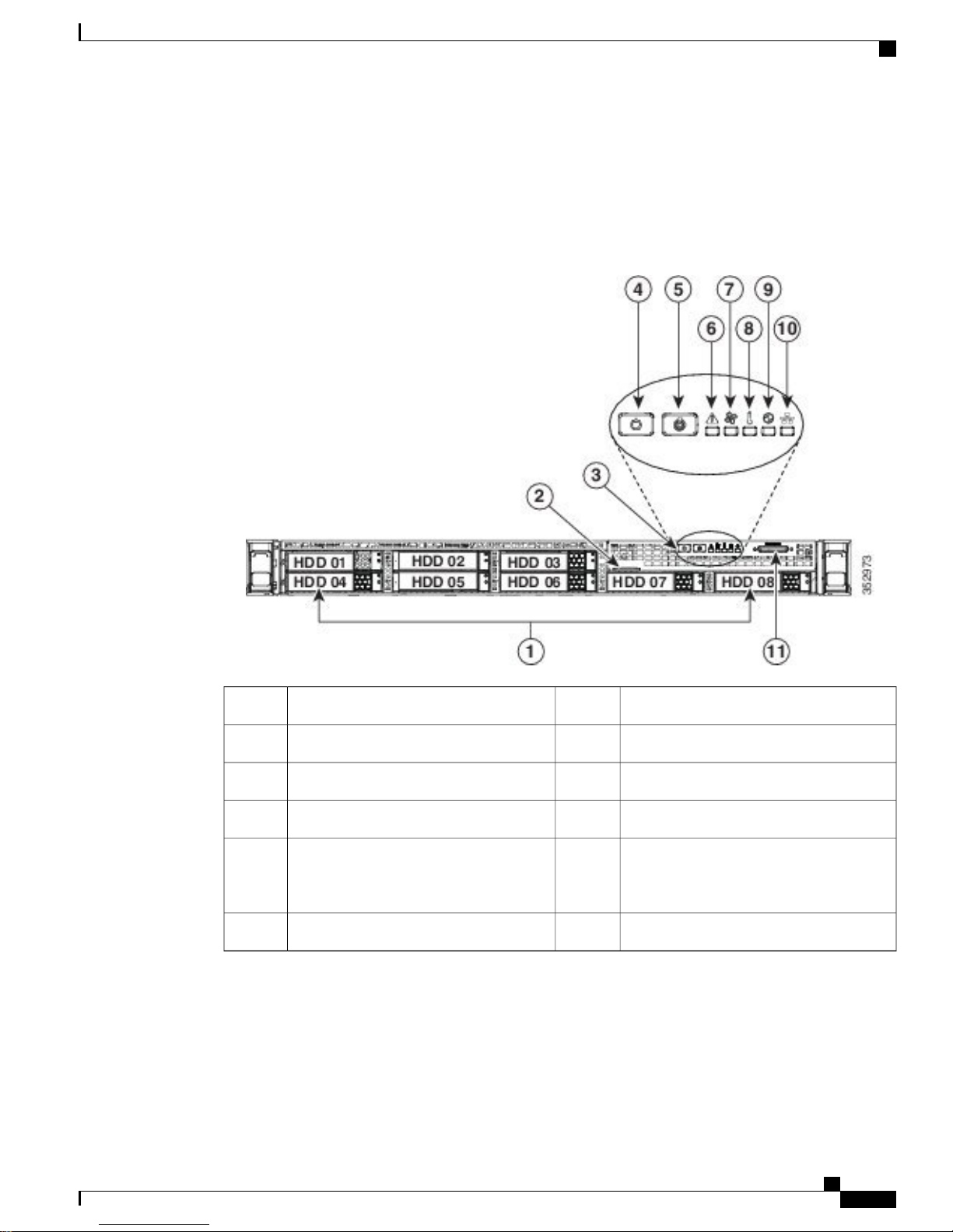
The following figure shows the components of the Cisco SNS-3515 or Cisco SNS-3595 appliance front panel
view.
Figure 1: Front Panel LEDs
Cisco SNS 3500 Series Appliances
Fan status LED7Drives (up to four 2.5-inch drives)1
Temperature status LED8Pull-out asset tag2
Power supply status LED9Operations panel buttons and LEDs3
Network link activity LED10Power button/power status LED4
11Unit identification button/LED5
KVM connector (used with KVM cable that
provides two USB 2.0, one VGA, and one
serial connector)
System status LED6
The following table describes the LEDs located on the front panel of the Cisco SNS-3515 or Cisco SNS-3595
appliance.
Cisco Identity Services Engine Hardware Installation Guide, Release 2.0.1
3
Page 4

Cisco SNS 3500 Series Appliances
Front Panel LEDs
Install Cisco ISE Software on the SNS 3515 and SNS 3595 Appliances
Hard drive fault
Hard drive activity
Power button/LED
• Off—The hard drive is operating properly.
• Amber—Drive fault detected.
• Amber, blinking—The device is rebuilding.
Amber, blinking with one-second
•
interval—Drive locate function activated.
• Off—There is no hard drive in the hard drive
tray (no access, no fault).
• Green—The hard drive is ready.
• Green, blinking—The hard drive is reading or
writing data.
• Off—There is no AC power to the server.
• Amber—The server is in standby power mode.
Power is supplied only to the Cisco IMC and
some motherboard functions.
• Green—The server is in main power mode.
Power is supplied to all server components.
Unit identification
• Off—The unit identification function is not in
use.
• Blue—The unit identification function is
activated.
Cisco Identity Services Engine Hardware Installation Guide, Release 2.0.1
4
Page 5

Install Cisco ISE Software on the SNS 3515 and SNS 3595 Appliances
Front Panel LEDs
Cisco SNS 3500 Series Appliances
System status
• Green—The server is running in normal
operating condition.
• Green, blinking—The server is performing
system initialization and memory check.
• Amber, steady—The server is in a degraded
operational state. For example:
Power supply redundancy is lost.
◦
CPUs are mismatched.
◦
At least one CPU is faulty.
◦
At least one DIMM is faulty.
◦
At least one drive in a RAID configuration
◦
failed.
• Amber, blinking—The server is in a critical
fault state. For example:
Boot failed.
◦
Fatal CPU and/or bus error is detected.
◦
Server is in an over-temperature condition.
◦
Fan status
Temperature status
• Green—All fan modules are operating properly.
• Amber, steady—One or more fan modules
breached the critical threshold.
• Amber, blinking—One or more fan modules
breached the non-recoverable threshold.
• Green—The server is operating at normal
temperature.
• Amber, steady—One or more temperature
sensors breached the critical threshold.
• Amber, blinking—One or more temperature
sensors breached the non-recoverable threshold.
Cisco Identity Services Engine Hardware Installation Guide, Release 2.0.1
5
Page 6
Cisco SNS 3500 Series Appliances
Front Panel LEDs
Install Cisco ISE Software on the SNS 3515 and SNS 3595 Appliances
Power supply status
Network link activity
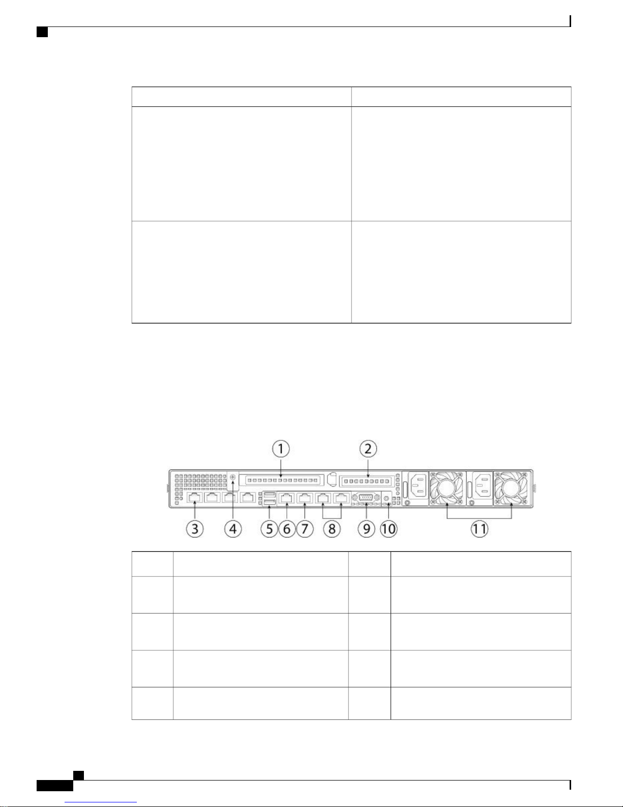
Cisco SNS 3515 or SNS 3595 Appliance Back Panel View
The following figure shows the components of the Cisco SNS-3515 and Cisco 3595 appliance back panel
view.
• Green—All power supplies are operating
normally.
• Amber, steady—One or more power supplies
are in a degraded operational state.
• Amber, blinking—One or more power supplies
are in a critical fault state.
• Off—The Ethernet link is idle.
• Green—One or more Ethernet LOM ports are
link-active, but there is no activity.
• Green, blinking—One or more Ethernet LOM
ports are link-active, with activity.
Figure 2: Back Panel LEDs
3
card slot
4
supplies)
Serial port (RJ-45 connector)7PCIe riser 1/slot 11
8PCIe riser 2/slot 22
Dual 1-GbE Ethernet ports (LAN1 and
LAN2)
VGA video port (DB-15)9Modular LAN-on-motherboard (mLOM)
Rear unit identification button/LED10Grounding-lug hole (for DC power
11USB 3.0 ports (two)5
Power supplies (up to two, redundant as
1+1)
Cisco Identity Services Engine Hardware Installation Guide, Release 2.0.1
6
Page 7
Install Cisco ISE Software on the SNS 3515 and SNS 3595 Appliances
Cisco SNS 3500 Series Appliances
6
1-GbE Ethernet dedicated management
port
The following table describes the LEDs located on the back panel of the Cisco SNS 3515 or Cisco SNS 3595
appliance.
StateLED Name
Optional mLOM 1-GbE SFP+ (there is a single status
LED)
• Off—No link is present.
• Green, steady—Link is active.
• Green, blinking—Traffic is present on the active
link.
Optional mLOM 1-GbE BASE-T link speed
• Off—Link speed is 10 Mbps.
• Amber—Link speed is 100 Mbps/1 Gbps.
• Green—Link speed is 10 Gbps.
Optional mLOM 1-GbE BASE-T link status
• Off—No link is present.
1-GbE Ethernet dedicated management link speed
1-GbE Ethernet dedicated management link status
1-GbE Ethernet link speed
• Green—Link is active.
• Green, blinking—Traffic is present on the active
link.
• Off—Link speed is 10 Mbps.
• Amber—Link speed is 100 Mbps.
• Green—Link speed is 1 Gbps.
• Off—No link is present.
• Green—Link is active.
• Green, blinking—Traffic is present on the active
link.
• Off—Link speed is 10 Mbps.
• Amber—Link speed is 100 Mbps.
• Green—Link speed is 1 Gbps.
Cisco Identity Services Engine Hardware Installation Guide, Release 2.0.1
7
Page 8

Cisco SNS 3500 Series Appliances
Install Cisco ISE Software on the SNS 3515 and SNS 3595 Appliances
StateLED Name
1-GbE Ethernet link status
Rear unit identification
Power supply status
• Off—No link is present.
• Green—Link is active.
• Green, blinking—Traffic is present on the active
link.
• Off—The unit identification LED is not in use.
• Blue—The unit identification LED is activated.
AC power supplies:
• Off—No AC input (12 V main power off, 12 V
standby power off).
• Green, blinking—12 V main power off; 12 V
standby power on.
• Green, solid—12 V main power on; 12 V
standby power on.
• Amber, blinking—Warning detected but 12 V
main power on.
• Amber, solid—Critical error detected; 12 V
main power off.
Internal Diagnostic LEDs
The server has internal fault LEDs for CPUs, DIMMs, fan modules, SD cards, the RTC battery, and the mLOM
card. These LEDs are available only when the server is in standby power mode. An LED lights amber to
indicate a faulty component.
Power must be connected to the server for these LEDs to be operate.Note
Cisco Identity Services Engine Hardware Installation Guide, Release 2.0.1
8
Page 9
Install Cisco ISE Software on the SNS 3515 and SNS 3595 Appliances
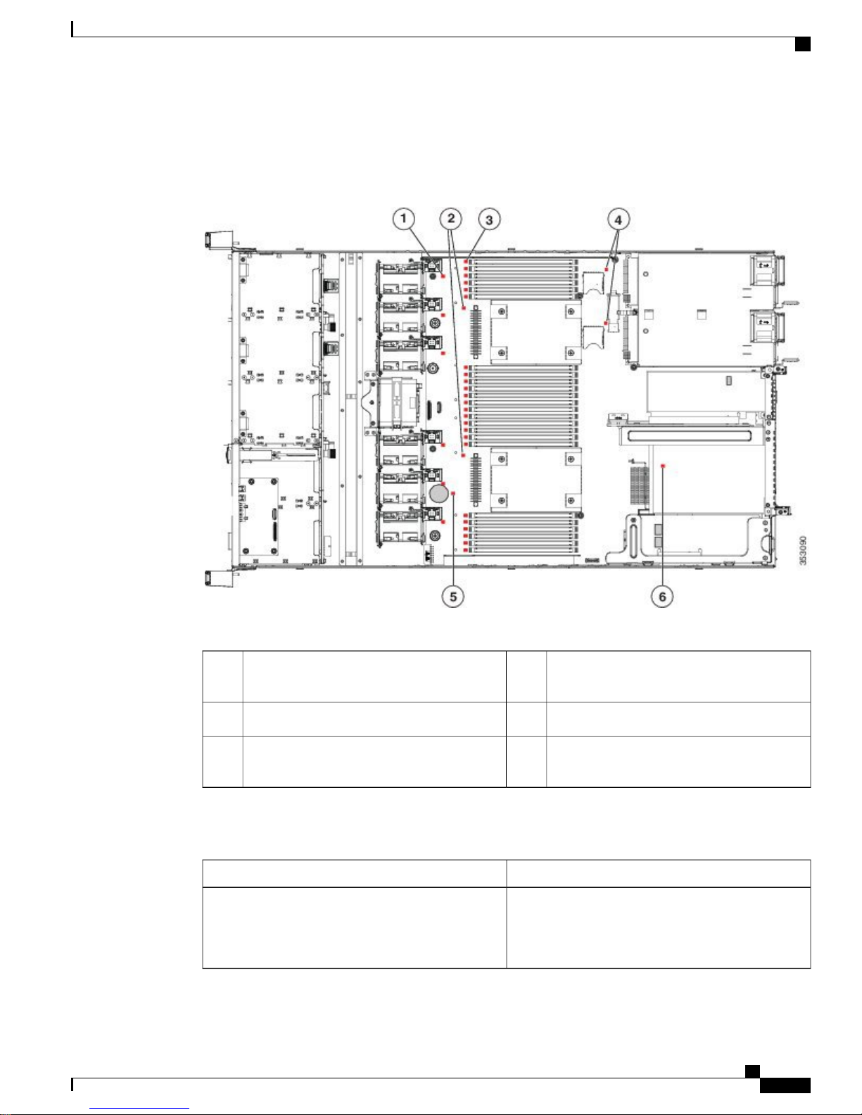
The following figure shows the locations of these internal LEDs in Cisco SNS-3515 or Cisco SNS-3595
appliance.
Figure 3: Cisco SNS-3515 or 3595 Internal Diagnostic LED Locations
Cisco SNS 3500 Series Appliances
The following table describes the callouts in the above figure.
1
SD card fault LEDs (one next to each bay)4Fan module fault LEDs (one next to each fan
connector on the motherboard)
RTC battery fault LED5CPU fault LEDs (one in front of each CPU)2
mLOM card fault LED (on motherboard next
3
DIMM socket on the motherboard)
6DIMM fault LEDs (one in front of each
to mLOM socket)
The following table describes the internal diagnostic LEDs located inside the Cisco SNS-3515 or Cisco
SNS-3595 appliance.
StateLED Name
Internal diagnostic LEDs (all)
• Off—Component is functioning normally.
• Amber—Component has failed.
Cisco Identity Services Engine Hardware Installation Guide, Release 2.0.1
9
Page 10

Before You Begin
Regulatory Compliance
For regulatory compliance and safety information, see Regulatory Compliance and Safety Information for
Cisco SNS-3415 and Cisco SNS-3495 Appliances.
Before You Begin
This section provides information on how you can prepare your site for safely installing the Cisco SNS-3515
or Cisco SNS-3595 appliance.
Safety Guidelines
Install Cisco ISE Software on the SNS 3515 and SNS 3595 Appliances
Note
Before you install, operate, or service a Cisco SNS-3515 or Cisco SNS-3595 appliance, review the
Regulatory Compliance and Safety Information for Cisco SNS-3515 and Cisco SNS-3595 Appliances for
important safety information.
Warning: IMPORTANT SAFETY INSTRUCTIONS
This warning symbol means danger. You are in a situation that could cause bodily injury. Before you work
on any equipment, be aware of the hazards involved with electrical circuitry and be familiar with standard
practices for preventing accidents. Use the statement number provided at the end of each warning to locate
its translation in the translated safety warnings that accompanied this device.
Statement 1071
Warning: To prevent the system from overheating, do not operate it in an area that exceeds the maximum
recommended ambient temperature of: 40° C (104° F).
Statement 1047
Warning: The plug-socket combination must be accessible at all times, because it serves as the main
disconnecting device.
Statement 1019
This product relies on the building’s installation for short-circuit (overcurrent) protection. Ensure that the
protective device is rated not greater than: 250 V, 15 A.
Statement 1005
Installation of the equipment must comply with local and national electrical codes.
Statement 1074
When you are installing a server, use the following guidelines
Plan your site configuration and prepare the site before installing the server. See the Cisco UCS Site
•
Preparation Guide for the recommended site planning tasks.
Ensure that there is adequate space around the server to allow for servicing the server and for adequate
•
airflow. The airflow in this server is from front to back.
Cisco Identity Services Engine Hardware Installation Guide, Release 2.0.1
10
Page 11
Install Cisco ISE Software on the SNS 3515 and SNS 3595 Appliances
Ensure that the air-conditioning meets the thermal requirements listed in the Server Specifications, on
•
page 13.
Ensure that the cabinet or rack meets the requirements listed in the Rack Requirements, on page 13.
•
Ensure that the site power meets the power requirements listed in the Power Specifications, on page
•
15. If available, you can use an uninterruptible power supply (UPS) to protect against power failures.
Unpack and Inspect the Server
Caution
Avoid UPS types that use ferroresonant technology. These UPS types can become unstable with systems
such as the Cisco UCS, which can have substantial current draw fluctuations from fluctuating data traffic
patterns.
Unpack and Inspect the Server
Caution
Note
When handling internal server components, wear an ESD strap and handle modules by the carrier edges
only.
Keep the shipping container in case the server requires shipping in the future.Note
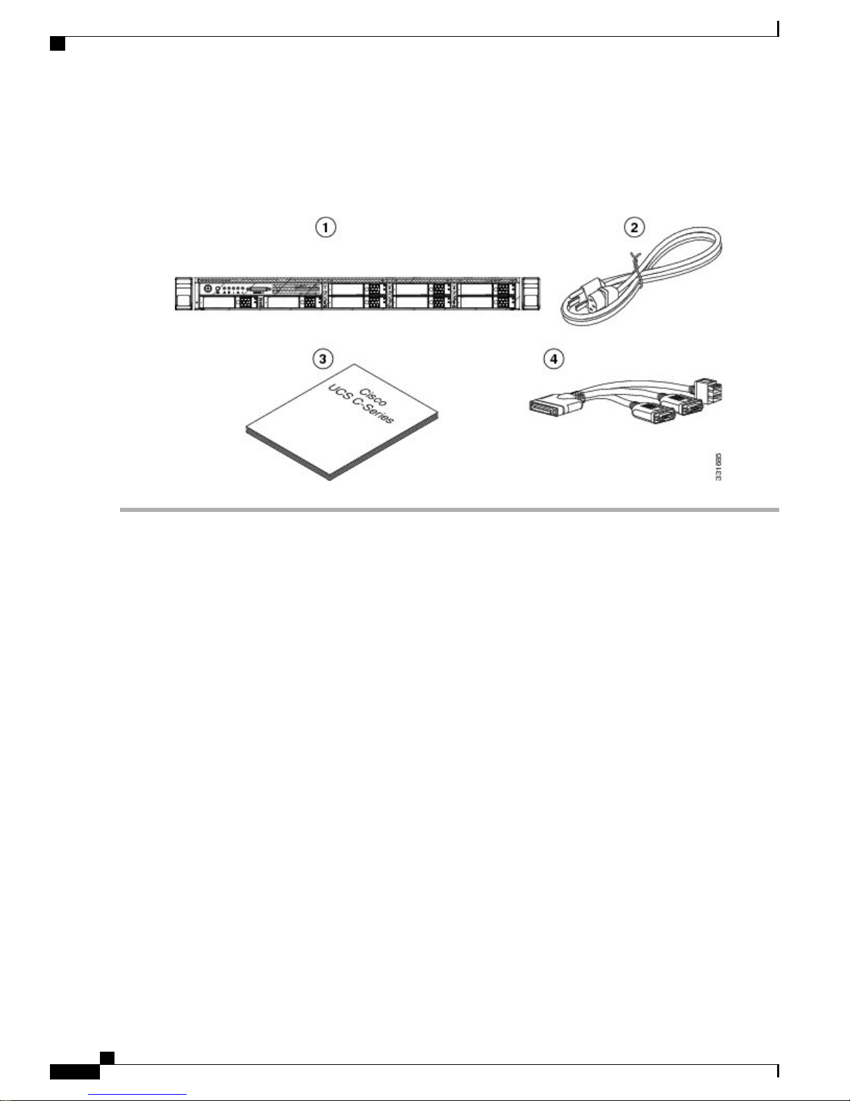
The chassis is thoroughly inspected before shipment. If any damage occurred during transportation or any
items are missing, contact your customer service representative immediately.
To inspect the shipment:
Step 1
Step 2
Remove the server from its cardboard container and save all packaging material.
Compare the shipment to the equipment list provided by your customer service representative and the list given below.
Verify that you have all items.
Step 3
Check for damage and report any discrepancies or damage to your customer service representative. Have the following
information ready:
Invoice number of shipper (see the packing slip)
•
Model and serial number of the damaged unit
•
Description of damage
•
Cisco Identity Services Engine Hardware Installation Guide, Release 2.0.1
11
Page 12
Prepare for Server Installation
Effect of damage on the installation
•
Figure 4: Shipping Box Contents
Install Cisco ISE Software on the SNS 3515 and SNS 3595 Appliances
Prepare for Server Installation
Installation Guidelines, on page 12
•
Rack Requirements, on page 13
•
Equipment Requirements, on page 13
•
Slide Rail Adjustment Range, on page 13
•
Installation Guidelines
Warning: To prevent the system from overheating, do not operate it in an area that exceeds the maximum
recommended ambient temperature of: 40° C (104° F).
Statement 1047
Warning: The plug-socket combination must be accessible at all times, because it serves as the main
disconnecting device.
Statement 1019
This product relies on the building’s installation for short-circuit (overcurrent) protection. Ensure that the
protective device is rated not greater than: 250 V, 15 A.
Statement 1005
Installation of the equipment must comply with local and national electrical codes.
Cisco Identity Services Engine Hardware Installation Guide, Release 2.0.1
12
Page 13

Install Cisco ISE Software on the SNS 3515 and SNS 3595 Appliances
Statement 1074
Server Specifications
Caution
Avoid UPS types that use ferroresonant technology. These UPS types can become unstable with systems
such as the Cisco UCS, which can have substantial current draw fluctuations from fluctuating data traffic
patterns.
When you are installing a server, use the following guidelines
Plan your site configuration and prepare the site before installing the server. See the Cisco UCS Site
•
Preparation Guide for the recommended site planning tasks.
Ensure that there is adequate space around the server to allow for servicing the server and for adequate
•
airflow. The airflow in this server is from front to back.
Ensure that the air-conditioning meets the thermal requirements listed in the Server Specifications, on
•
page 13.
Ensure that the cabinet or rack meets the requirements listed in the Rack Requirements, on page 13.
•
Ensure that the site power meets the power requirements listed in the Power Specifications, on page
•
15. If available, you can use an uninterruptible power supply (UPS) to protect against power failures.
Rack Requirements
This section provides the requirements for the standard open racks.
The rack must be of the following type:
A standard 19-in. (48.3-cm) wide, four-post EIA rack, with mounting posts that conform to English
•
universal hole spacing, per section 1 of ANSI/EIA-310-D-1992.
The rack post holes can be square 0.38-inch (9.6 mm), round 0.28-inch (7.1 mm), #12-24 UNC, or
•
#10-32 UNC when you use the supplied slide rails.
The minimum vertical rack space per server must be one RU, equal to 1.75 in. (44.45 mm).
•
Equipment Requirements
The slide rails supplied by Cisco Systems for this server do not require tools for installation. The inner rails
(mounting brackets) are pre-attached to the sides of the server.
Slide Rail Adjustment Range
The slide rails for this server have an adjustment range of 24 to 36 inches (610 to 914 mm).
Server Specifications
This section lists the technical specifications for the server and includes the following sections:
Cisco Identity Services Engine Hardware Installation Guide, Release 2.0.1
13
Page 14
Server Specifications
Physical Specifications
The following table lists the physical specifications of the server.
Install Cisco ISE Software on the SNS 3515 and SNS 3595 Appliances
SpecificationDescription
1.7 in. (4.3 cm)Height
16.9 in. (42.9 cm)Width
29.8 in. (75.8 cm)Depth
Weight (fully loaded chassis)
Environmental Specifications
The following table lists the environmental specifications of the server.
Temperature, operating
or transported)
SNS 3515: 37.9 lb. (17.2 Kg)
SNS 3595: 39.9 lb. (18.1 Kg)
SpecificationDescription
41 to 104°F (5 to 40°C)
Derate the maximum temperature by 1°C every 305
meters of altitude above sea level.
-40 to 149°F (-40 to 65°C)Temperature, non-operating (when the server is stored
10 to 90%Humidity (RH), noncondensing
0 to 10,000 feetAltitude, operating
0 to 40,000 feetAltitude, non-operating
Measure A-weighted per ISO7779 LwAd (Bels)
Operation at 73°F (23°C)
Measure A-weighted per ISO7779 LpAm (dBA)
Operation at 73°F (23°C)
Cisco Identity Services Engine Hardware Installation Guide, Release 2.0.1
14
5.4Sound power level
37Sound pressure level
Page 15

Install Cisco ISE Software on the SNS 3515 and SNS 3595 Appliances
Power Specifications
The power specifications for the power supply options are listed in the following section:
Do not mix power supply types in the server. Both power supplies must be identical.Note
770-WAC Power Supply
Install the Cisco SNS 3515 and Cisco SNS 3595 Hardware Appliances
SpecificationDescription
AC input voltage range
AC input frequency
AC line input current (steady state)
Power supply output voltage
90 to 264 VAC (self-ranging, 100 to 264 VAC
nominal)
Range: 47 to 63 Hz (single phase, 50 to 60 Hz
nominal)
9.5 A peak at 100 VAC
4.5 A peak at 208 VAC
770 WMaximum output power for each power supply
Main power: 12 VDC
Standby power: 12 VDC
Install the Cisco SNS 3515 and Cisco SNS 3595 Hardware
Appliances
This section describes how to install your Cisco SNS 3515 or 3595 appliance and connect it to the network.
It contains:
Install the Cisco SNS 3515 or 3595 Appliance in a Rack, on page 16
•
Cisco Integrated Management Controller, on page 27
•
Connect Cables, on page 21
•
Connect and Power On the Cisco SNS 3515 or 3595 Appliance, on page 25
•
Before you begin the installation, read the Regulatory Compliance and Safety Information for the Cisco SNS
3515 or Cisco SNS 3595 Hardware Appliance.
Warning: Only trained and qualified personnel should be allowed to install, replace, or service this equipment.
Statement 1030
Warning: This unit is intended for installation in restricted access areas. A restricted access area can be accessed
only through the use of a special tool, lock and key, or other means of security.
Cisco Identity Services Engine Hardware Installation Guide, Release 2.0.1
15
Page 16

Install Cisco ISE Software on the SNS 3515 and SNS 3595 Appliances
Install the Cisco SNS 3515 or 3595 Appliance in a Rack
Statement 1017
Install the Cisco SNS 3515 or 3595 Appliance in a Rack
This section describes how to install the Cisco SNS 3515 or Cisco SNS 3595 appliance in a rack.
Install the Side Rails
Warning: To prevent bodily injury when mounting or servicing this unit in a rack, you must take special
precautions to ensure that the system remains stable. The following guidelines are provided to ensure your
safety:
This unit should be mounted at the bottom of the rack if it is the only unit in the rack. When mounting this
unit in a partially filled rack, load the rack from the bottom to the top with the heaviest component at the
bottom of the rack.
If the rack is provided with stabilizing devices, install the stabilizers before mounting or servicing the unit in
the rack.
Statement 1006
Step 1
Step 2
Attach the inner rails to the sides of the server:
Figure 5: Attach Inner Rail to Side of Server
Locking clip on inner rail2Front side of the server1
a) Align an inner rail with one side of the server so that the three keyed slots in the rail align with the three pegs on the
side of the server (see the figure above).
b) Set the keyed slots over the pegs, and then slide the rail toward the front to lock it in place on the pegs. The front slot
has a metal clip that locks over the front peg.
c) Install the second inner rail to the opposite side of the server.
Open the front securing plate on both slide-rail assemblies. The front end of the slide-rail assembly has a spring-loaded
securing plate that must be open before you can insert the mounting pegs into the rack-post holes.
Cisco Identity Services Engine Hardware Installation Guide, Release 2.0.1
16
Page 17

Install Cisco ISE Software on the SNS 3515 and SNS 3595 Appliances
On the outside of the assembly, push the green arrow button toward the rear to open the securing plate.
Figure 6: Front Securing Mechanism, Inside of Front End
Install the Cisco SNS 3515 or 3595 Appliance in a Rack
Step 3
Step 4
Securing plate shown pulled back to open position3Front mounting pegs1
Rack post2
Install the outer slide rails into the rack:
a) Align one slide-rail assembly front end with the front rack-post holes that you want to use. The slide rail front-end
wraps around the outside of the rack post and the mounting pegs enter the rack-post holes from the outside-front (see
the figure above).
Note
The rack post must be between the mounting pegs and the open securing
plate.
b) Push the mounting pegs into the rack-post holes from the outside-front.
c) Press the securing plate release button, marked PUSH. The spring-loaded securing plate closes to lock the pegs in
place.
d) Adjust the slide-rail length, and then push the rear mounting pegs into the corresponding rear rack-post holes. The
slide rail must be level front-to-rear.
The rear mounting pegs enter the rear rack-post holes from the inside of the rack post.
e) Attach the second slide-rail assembly to the opposite side of the rack. Ensure that the two slide-rail assemblies are
at the same height with each other and are level front-to-back.
f) Pull the inner slide rails on each assembly out toward the rack front until they hit the internal stops and lock in place.
Insert the server into the slide rails:
Cisco Identity Services Engine Hardware Installation Guide, Release 2.0.1
17
Page 18

Install the Cisco SNS 3515 or 3595 Appliance in a Rack
Install Cisco ISE Software on the SNS 3515 and SNS 3595 Appliances
Step 5
Caution
This server can weigh up to 67 pounds (59 kilograms) when fully loaded with components. We recommend
that you use a minimum of two people or a mechanical lift when lifting the server. Attempting this procedure
alone could result in personal injury or equipment damage.
Figure 7: Inner Rail Release Clip
Outer rail attached to rack post3Inner rail release clip1
Inner rail attached to server and inserted into outer
2
rail
(Optional) Secure the server in the rack more permanently by using the two screws that are provided with the slide rails.
Perform this step if you plan to move the rack with servers installed.
With the server fully pushed into the slide rails, open a hinged slam latch lever on the front of the server and insert the
screw through the hole that is under the lever. The screw threads into the static part of the rail on the rack post and
prevents the server from being pulled out. Repeat for the opposite slam latch.
Cisco Identity Services Engine Hardware Installation Guide, Release 2.0.1
18
Page 19

Install Cisco ISE Software on the SNS 3515 and SNS 3595 Appliances
What to Do Next
Install the Cable Management Arm (Optional)
Install the Cisco SNS 3515 or 3595 Appliance in a Rack
Step 1
Step 2
Step 3
Step 4
Step 5
Note
The CMA is reversible left to right. To reverse the CMA, see Reversing the Cable Management Arm
(Optional) before installation.
With the server pushed fully into the rack, slide the CMA tab of the CMA arm that is farthest from the server onto the
end of the stationary slide rail that is attached to the rack post (see the following figure). Slide the tab over the end of
the rail until it clicks and locks.
Slide the CMA tab that is closest to the server over the end of the inner rail that is attached to the server (see the following
figure). Slide the tab over the end of the rail until it clicks and locks.
Pull out the width-adjustment slider that is at the opposite end of the CMA assembly until it matches the width of your
rack (see the following figure).
Slide the CMA tab that is at the end of the width-adjustment slider onto the end of the stationary slide rail that is attached
to the rack post (see the following figure). Slide the tab over the end of the rail until it clicks and locks.
Open the hinged flap at the top of each plastic cable guide and route your cables through the cable guides as desired.
Figure 8: Attach the Cable Management Arm to the Rear of the Slide Rails
Cisco Identity Services Engine Hardware Installation Guide, Release 2.0.1
19
Page 20

Install the Cisco SNS 3515 or 3595 Appliance in a Rack
Install Cisco ISE Software on the SNS 3515 and SNS 3595 Appliances
1
stationary outer slide rail
2
inner slide rail attached to server
CMA tab on width-adjustment slider and end of
3CMA tab on arm farthest from server and end of
stationary outer slide rail
Rear of server4CMA tab on arm closest to the server and end of
Cisco Identity Services Engine Hardware Installation Guide, Release 2.0.1
20
Page 21

Install Cisco ISE Software on the SNS 3515 and SNS 3595 Appliances
Reverse the Cable Management Arm (Optional)
Connect Cables
Step 1
Step 2
Step 3
Rotate the entire CMA assembly 180 degrees. The plastic cable guides must remain pointing upward.
Flip the tabs at the end of each CMA arm so that they point toward the rear of the server.
Pivot the tab that is at the end of the width-adjustment slider. Depress and hold the metal button on the outside of the
tab and pivot the tab 180 degrees so that it points toward the rear of the
Figure 9: Reverse the CMA
Metal button for rotating2CMA tab on end of width-adjustment slider1
Connect Cables
This section describes how to connect your Cisco SNS-3515 or Cisco SNS-3595 appliance to the network
and the appliance console.
Connect the Network Interface, on page 22
•
Connect the Console, on page 23
•
Connect the Keyboard and Video Monitor, on page 24
•
Cable Management, on page 24
•
Attach cables (such as keyboard, monitor cables, if required) to the rear of the server. Route the cables properly
and use the cable straps to secure the cables to the slide rails. See the Cisco SNS 3515 or SNS 3595 Appliance
Back Panel View, on page 6 for reference on the rear view of the appliance.
Cisco Identity Services Engine Hardware Installation Guide, Release 2.0.1
21
Page 22

Connect Cables
Connect the Network Interface
Warning: Do not work on the system or connect or disconnect cables during periods of lightning activity.
Statement 1001
This section describes how to connect the Cisco SNS-3515 or Cisco SNS-3595 appliance Ethernet port.
The Ethernet connector supports Serial over LAN (SOL) cables. The RJ-45 port supports standard
straight-through and crossover Category 5 unshielded twisted-pair (UTP) cables. Cisco does not supply
Category 5 UTP cables; these cables are available commercially.
To connect the cable to the appliance Ethernet port:
Install Cisco ISE Software on the SNS 3515 and SNS 3595 Appliances
Step 1
Step 2
Step 3
Verify that the appliance is turned off.
Connect one end of the cable to the GigabitEthernet 0 port on the appliance.
Connect the other end to a switch in your network.
Ethernet Port Connector
The Cisco SNS 3515 or Cisco SNS-3595 appliance comes with six integrated dual-port Ethernet controllers.
The controllers provide an interface for connecting to 10-Mb/s, 100-Mb/s, or 1000-Mb/s networks and provide
full-duplex (FDX) capability, which enables simultaneous transmission and reception of data on the Ethernet
LAN. Cisco ISE supports multiple NICs.
To access the Ethernet port, connect a Category 3, 4, 5, 5E, or 6 unshielded twisted-pair (UTP) cable to the
RJ-45 connector on the back of the appliance.
The following table describes the UTP cable categories.
DescriptionType
10BASE-T
EIA Categories 3, 4, or 5 UTP (2 or 4 pair) up to 328
ft (100 m)
EIA Category 5 UTP (2 pair) up to 328 ft (100 m)100BASE-TX
1000BASE-T
EIA Category 6 UTP (recommended), Category 5E
UTP or 5 UTP (2 pair) up to 328 ft (100 m)
Cisco Identity Services Engine Hardware Installation Guide, Release 2.0.1
22
Page 23

Install Cisco ISE Software on the SNS 3515 and SNS 3595 Appliances
The following figure shows the RJ-45 port and plug.
Figure 10: RJ-45 Port and Plug
Ethernet Port Pin-out
Pin
Connect Cables
DescriptionSignalEthernet Port
Transmit data +TxD+1
Transmit data -TxD-2
4
5
7
8
Connect the Console
Warning: Do not work on the system or connect or disconnect cables during periods of lightning activity.
Statement 1001
Your Cisco SNS-3515 or Cisco SNS-3595 appliance has a DCE-mode console port for connecting a console
terminal to your appliance. The appliance uses a DB-9 serial connector for the console port.
The console port on the Cisco SNS-3515 or Cisco SNS-3595 appliance includes an EIA/TIA-232 asynchronous
serial (DB-9) connector. This serial console connector (port) allows you to access the appliance locally by
connecting a terminal—either a PC running terminal-emulation software or an ASCII terminal—to the console
port.
Receive data +RxD+3
No connectionTermination
network
No connectionTermination
network
Receive data-RxD-6
No connectionTermination
network
No connectionTermination
network
Cisco Identity Services Engine Hardware Installation Guide, Release 2.0.1
23
Page 24

Connect Cables
Install Cisco ISE Software on the SNS 3515 and SNS 3595 Appliances
To connect a PC running terminal-emulation software to the console port, use a DB-9 female to DB-9 female
straight-through cable.
To connect an ASCII terminal to the console port, use a DB-9 female to DB-25 male straight-through cable
with a DB-25 female to DB-25 female gender changer.
To connect a terminal or a PC running terminal-emulation software to the console port on the Cisco SNS-3515
or Cisco SNS-3595 appliance:
Step 1
Step 2
Connect the terminal using a straight-through cable to the console port.
Configure your terminal or terminal-emulation software for 9600 baud, 8 data bits, no parity, 1 stop bit, and no hardware
flow control.
Connect the Keyboard and Video Monitor
Do not work on the system or connect or disconnect cables during periods of lightning activity.
Statement 1001
This section describes how to connect a keyboard and video monitor to the Cisco SNS-3515 or Cisco SNS-3595
appliance.
You can connect the keyboard and video monitor to the Cisco SNS-3515 or Cisco SNS-3595 appliance using
the KVM connector available in the front panel of the Cisco SNS-3515 or Cisco SNS-3595 appliance. A KVM
cable is shipped along with the appliance that provides two USB, one VGA, and one serial connector.
The Cisco SNS-3515 or Cisco SNS-3595 appliance does not provide support for a mouse.
The Cisco SNS-3515 or Cisco SNS-3595 provides USB ports on the rear of the appliance that can be used to
connect a keyboard and video monitor.
To connect a keyboard and video monitor to the appliance:
Step 1
Step 2
Step 3
Verify that the appliance is turned off.
Connect the end of the keyboard cable to the PS/2 (keyboard) port which is located on the back panel of the appliance.
Connect the end of the video monitor cable to the PS/2 (video monitor) port which is located on the back panel of the
appliance.
Step 4
Power on the appliance.
Cable Management
Cable management is the most visual aspect of your appliance setup. However, cable management is often
overlooked because it can be time consuming.
Equipment racks and enclosures house more equipment today than ever before. This growth has increased
the need for organized cable management both inside and outside the rack. Poor cable management not only
Cisco Identity Services Engine Hardware Installation Guide, Release 2.0.1
24
Page 25

Install Cisco ISE Software on the SNS 3515 and SNS 3595 Appliances
Connect and Power On the Cisco SNS 3515 or 3595 Appliance
leads to damaged cables or increased time for adding or changing cables, but also blocks critical airflow or
access. These problems can lead to inefficiencies in the performance of your equipment or even downtime.
There are many solutions to address cable management. They can range from simple cable management rings,
to vertical or horizontal organizers, to troughs and ladders.
All Cisco SNS-3515 or Cisco SNS-3595 appliance cables should be properly dressed so as not to interfere
with each other or other pieces of equipment. Use local practices to ensure that the cables attached to your
appliance are properly dressed.
Proceed to the next section, Connect and Power On the Cisco SNS 3515 or 3595 Appliance, on page 25, to
continue the installation process.
Connect and Power On the Cisco SNS 3515 or 3595 Appliance
Connect and Power On the Server (Standalone Mode), on page 25
•
NIC Modes and NIC Redundancy Settings, on page 29
•
System BIOS and CIMC Firmware
•
Connect and Power On the Server (Standalone Mode)
Note
This section describes how to power on the server, assign an IP address, and connect to server management
when using the server in standalone mode.
The server is shipped with the following default settings:
The NIC mode is Shared LOM EXT.
•
Shared LOM EXT mode enables the 1-Gb Ethernet ports and the ports on any installed Cisco virtual
interface card (VIC) to access Cisco Integrated Management Interface (Cisco IMC). If you want to use
the 10/100/1000 dedicated management ports to access Cisco IMC, you can connect to the server and
change the NIC mode as described in Step 1 of the procedures given below.
The NIC redundancy is active-active.
•
All Ethernet ports are utilized simultaneously.
DHCP is enabled.
•
IPv4 is enabled.
•
You can connect to the system using two methods:
• Local setup—Use this procedure if you want to connect a keyboard and monitor to the system for setup.
This procedure can use a KVM cable (Cisco PID N20-BKVM) or the ports on the rear of the server.
See Local Connection Procedure, on page 26.
• Remote setup—Use this procedure if you want to perform setup through your dedicated management
LAN. See Remote Connection Procedure, on page 26.
Cisco Identity Services Engine Hardware Installation Guide, Release 2.0.1
25
Page 26

Connect and Power On the Cisco SNS 3515 or 3595 Appliance
Install Cisco ISE Software on the SNS 3515 and SNS 3595 Appliances
Note
Local Connection Procedure
Step 1
Attach a power cord to each power supply unit in your server, and then attach each power cord to a grounded AC power
outlet. See Power Specifications, on page 15 for power specifications.
Wait for approximately two minutes to let the server boot in standby power during the first bootup.
You can verify system power status by looking at the system Power Status LED on the front panel (see LED Indicators
on Cisco SNS 3515 and 3595 Appliances, on page 2). The system is in standby power mode when the LED is amber.
Step 2
Connect a USB keyboard and VGA monitor to the server using one of the following methods:
Connect a USB keyboard and VGA monitor to the corresponding connectors on the rear panel (see Cisco SNS
•
3515 or SNS 3595 Appliance Back Panel View, on page 6).
Connect an optional KVM cable (Cisco PID N20-BKVM) to the KVM connector on the front panel (see Cisco
•
SNS-3515 or 3595 Appliance Front Panel View, on page 3 for the connector location). Connect your USB
keyboard and VGA monitor to the KVM cable.
To configure the system remotely, you must have a DHCP server on the same network as the system.
Your DHCP server must be preconfigured with the range of MAC addresses for this server node. The
MAC address is printed on a label on the rear of the server node. This server node has a range of six MAC
addresses assigned to the Cisco IMC. The MAC address printed on the label is the beginning of the range
of six contiguous MAC addresses.
Step 3
Open the Cisco IMC Configuration Utility:
a) Press and hold the front panel power button for four seconds to boot the server.
b) During bootup, press F8 when prompted to open the Cisco IMC Configuration Utility.
This utility has two windows that you can switch between by pressing F1 or F2.
c) Continue with Setup CIMC Configuration Utility, on page 27.
Remote Connection Procedure
Step 1
Attach a power cord to each power supply unit in your server, and then attach each power cord to a grounded AC power
outlet. See Power Specifications, on page 15 for power specifications.
Wait for approximately two minutes to let the server boot in standby power during the first bootup.
You can verify system power status by looking at the system Power Status LED on the front panel (see LED Indicators
on Cisco SNS 3515 and 3595 Appliances, on page 2). The system is in standby power mode when the LED is amber.
Cisco Identity Services Engine Hardware Installation Guide, Release 2.0.1
26
Page 27

Install Cisco ISE Software on the SNS 3515 and SNS 3595 Appliances
Connect and Power On the Cisco SNS 3515 or 3595 Appliance
Step 2
Plug your management Ethernet cable into the dedicated management port on the rear panel (see Cisco SNS 3515 or
SNS 3595 Appliance Back Panel View, on page 6).
Step 3
Step 4
Allow your preconfigured DHCP server to assign an IP address to the server node.
Use the assigned IP address to access and log in to the Cisco IMC for the server node. Consult with your DHCP server
administrator to determine the IP address.
The default user name for the server is admin. The default password is password.Note
Step 5
Step 6
Step 7
From the Cisco IMC Server Summary page, click Launch KVM Console. A separate KVM console window opens.
From the Cisco IMC Summary page, click Power Cycle Server. The system reboots.
Select the KVM console window.
Note
The KVM console window must be the active window for the following keyboard actions to
work.
Step 8
When prompted, press F8 to enter the Cisco IMC Configuration Utility. This utility opens in the KVM console window.
This utility has two windows that you can switch between by pressing F1 or F2.
Step 9
Continue with Setup CIMC Configuration Utility, on page 27.
Cisco Integrated Management Controller
You can monitor the server inventory, health, and system event logs by using the built-in Cisco Integrated
Management Controller 1.4.7a (CIMC) GUI or CLI interfaces. See the user documentation for your firmware
release at the following URL:
http://www.cisco.com/c/en/us/support/servers-unified-computing/ucs-c-series-integrated-management-controller/
products-installation-and-configuration-guides-list.html
Setup CIMC Configuration Utility
The following procedure is performed after you connect to the system and open the Cisco IMC Configuration
Utility.
Step 1
Set NIC mode and NIC redundancy:
a) Set the NIC mode to choose which ports to use to access Cisco IMC for server management:
• Shared LOM EXT (default)—This is the shared LOM extended mode, the factory-default setting. With this
mode, the Shared LOM and Cisco Card interfaces are both enabled.
In this mode, DHCP replies are returned to both the shared LOM ports and the Cisco card ports. If the system
determines that the Cisco card connection is not getting its IP address from a Cisco UCS Manager system
because the server is in standalone mode, further DHCP requests from the Cisco card are disabled. Use the
Cisco Card NIC mode if you want to connect to Cisco IMC through a Cisco card in standalone mode.
• Shared LOM—The 1-Gb Ethernet ports are used to access Cisco IMC. You must select a NIC redundancy and
IP setting.
• Dedicated—The dedicated management port is used to access Cisco IMC. You must select a NIC redundancy
and IP setting.
Cisco Identity Services Engine Hardware Installation Guide, Release 2.0.1
27
Page 28

Install Cisco ISE Software on the SNS 3515 and SNS 3595 Appliances
Connect and Power On the Cisco SNS 3515 or 3595 Appliance
• Cisco Card—The ports on an installed Cisco UCS virtual interface card (VIC) are used to access the Cisco
IMC. You must select a NIC redundancy and IP setting.
See also the required VIC Slot setting below.
• VIC Slot—If you use the Cisco Card NIC mode, you must select this setting to match where your VIC is
installed. The choices are Riser1, Riser2, or Flex-LOM (the mLOM slot).
If you select Riser1, slot 1 is used.
◦
If you select Riser2, slot 2 is used.
◦
If you select Flex-LOM, you must use an mLOM-style VIC in the mLOM slot.
◦
b) Use this utility to change the NIC redundancy to your preference. This server has three possible NIC redundancy
settings:
• None—The Ethernet ports operate independently and do not fail over if there is a problem. This setting can be
used only with the Dedicated NIC mode.
Step 2
Step 3
Step 4
• Active-standby—If an active Ethernet port fails, traffic fails over to a standby port.
• Active-active—All Ethernet ports are utilized simultaneously. The Shared LOM EXT mode can have only this
NIC redundancy setting. Shared LOM and Cisco Card modes can have both Active-standby and Active-active
settings.
Choose whether to enable DHCP for dynamic network settings, or to enter static network settings.
Note
Before you enable DHCP, you must preconfigure your DHCP server with the range of MAC addresses for this
server. The MAC address is printed on a label on the rear of the server. This server has a range of six MAC
addresses assigned to Cisco IMC. The MAC address printed on the label is the beginning of the range of six
contiguous MAC addresses.
The static IPv4 and IPv6 settings include the following:
The Cisco IMC IP address.
•
The prefix/subnet.
•
For IPv6, valid values are 1–127.
The gateway.
•
For IPv6, if you do not know the gateway, you can set it as none by entering :: (two colons).
The preferred DNS server address.
•
For IPv6, you can set this as none by entering :: (two colons).
(Optional) Use this utility to make VLAN settings.
Press F1 to go to the second settings window, then continue with the next step.
From the second window, you can press F2 to switch back to the first window.
Cisco Identity Services Engine Hardware Installation Guide, Release 2.0.1
28
Page 29

Install Cisco ISE Software on the SNS 3515 and SNS 3595 Appliances
Connect and Power On the Cisco SNS 3515 or 3595 Appliance
Step 5
Step 6
Step 7
Step 8
Step 9
Step 10
Step 11
Step 12
(Optional) Set a hostname for the server.
(Optional) Enable dynamic DNS and set a dynamic DNS (DDNS) domain.
(Optional) If you check the Factory Default check box, the server reverts to the factory defaults.
(Optional) Set a default user password.
(Optional) Enable auto-negotiation of port settings or set the port speed and duplex mode manually.
Note
Auto-negotiation is applicable only when you use the Dedicated NIC mode. Auto-negotiation sets the port speed
and duplex mode automatically based on the switch port to which the server is connected. If you disable
auto-negotiation, you must set the port speed and duplex mode manually.
(Optional) Reset port profiles and the port name.
Press F5 to refresh the settings that you made. You might have to wait about 45 seconds until the new settings appear
and the message, “Network settings configured” is displayed before you reboot the server in the next step.
Press F10 to save your settings and reboot the server.
Note
If you chose to enable DHCP, the dynamically assigned IP and MAC addresses are displayed on the console
screen during bootup.
Use a browser and the IP address of the Cisco IMC to connect to the Cisco IMC management interface. The IP
address is based upon the settings that you made (either a static address or the address assigned by your DHCP
server).
The default username for the server is admin. The default password is password.
To manage the server, see the Cisco UCS C-Series Rack-Mount Server Configuration Guide or the Cisco UCS C-Series
Rack-Mount Server CLI Configuration Guide for instructions on using those interfaces. The links to these documents
are in the C-Series documentation roadmap:
http://www.cisco.com/go/unifiedcomputing/c-series-doc
NIC Modes and NIC Redundancy Settings
NIC Modes
This server has the following NIC mode settings that you can choose from:
• Shared LOM EXT (default)—This is the Shared LOM extended mode, the factory-default setting. With
this mode, the shared LOM and Cisco Card interfaces are both enabled.
In this mode, DHCP replies are returned to both the shared LOM ports and the Cisco card ports. If the
system determines that the Cisco card connection is not getting its IP address from a Cisco UCS Manager
system because the server is in standalone mode, further DHCP requests from the Cisco card are disabled.
If the system determines that the Cisco card connection is getting its IP address from a Cisco UCS
Manager system, the reply has parameters that automatically move the server to UCSM mode.
• Dedicated—The dedicated management port is used to access Cisco IMC. You must select a NIC
redundancy and IP setting.
• Shared LOM—The 1-Gb Ethernet ports are used to access Cisco IMC. You must select a NIC redundancy
and IP setting.
• Cisco Card—The ports on an installed Cisco UCS virtual interface card (VIC) are used to access Cisco
IMC. You must select a NIC redundancy and IP setting.
Cisco Identity Services Engine Hardware Installation Guide, Release 2.0.1
29
Page 30

Install Cisco ISE Software on the SNS 3515 and SNS 3595 Appliances
See also the required VIC Slot setting below.
• VIC Slot—If you use the Cisco Card NIC mode, you select this setting to match where your VIC is
installed. The choices are Riser1, Riser2, or Flex-LOM (the mLOM slot).
If you select Riser1, slot 1 is used.
◦
If you select Riser2, slot 2 is used.
◦
If you select Flex-LOM, you must use an mLOM-style VIC in the mLOM sl
◦
NIC Redundancy
This server has the following NIC redundancy settings that you can choose from:
• None—The Ethernet ports operate independently and do not fail over if there is a problem. This setting
can be used only with the Dedicated NIC mode.
• Active-standby—If an active Ethernet port fails, traffic fails over to a standby port.
• Active-active—All Ethernet ports are utilized simultaneously. Shared LOM EXT mode can have only
this NIC redundancy setting. Shared LOM and Cisco Card modes can have both Active-standby and
Active-active settings.
The active/active setting uses Mode 5 or Balance-TLB (adaptive transmit load balancing). This is channel
bonding that does not require any special switch support. The outgoing traffic is distributed according
to the current load (computed relative to the speed) on each slave. Incoming traffic is received by the
current slave. If the receiving slave fails, another slave takes over the MAC address of the failed receiving
slave.
Install Cisco ISE Software on the SNS 3515 and SNS 3595 Appliances
Install Cisco ISE Software on the SNS 3515 and SNS 3595
Appliances
Install Cisco ISE on the Cisco SNS 3515 or 3595 Appliance
The Cisco SNS 3515 and Cisco SNS 3595 appliances are preinstalled with the ISE 2.0.1 software. This section
gives you an overview of the installation process and the tasks that you must perform before installing ISE.
Cisco Identity Services Engine Hardware Installation Guide, Release 2.0.1
30
Page 31

Install Cisco ISE Software on the SNS 3515 and SNS 3595 Appliances
Before you begin installing ISE 2.0.1, you must:
Download the Cisco ISE ISO Image
Step 1
Step 2
Step 3
Step 4
Step 5
Step 6
Step 7
Open the box and check the contents. See Unpack and Inspect the Server, on page 11.
Read about the Cisco SNS 3500 Series Appliances, on page 1.
Read the general precautions and safety warnings in Before You Begin, on page 10.
Install the appliance in the rack. See Prepare for Server Installation, on page 12.
Connect the Cisco SNS-3515 or Cisco SNS-3595 to the network and appliance console. See Connect Cables, on page
21.
Power up the Cisco SNS-3515 or Cisco SNS-3595 appliance. See Connect and Power On the Cisco SNS 3515 or 3595
Appliance, on page 25.
Run the setup command at the CLI prompt to configure the initial settings for the ISE server. See Run the Setup Program,
on page 35. The setup can be done by using the appliance console or CIMC.
You can use the Cisco UCS Server Configuration Utility, Release 3.0 User Guide to configure the Cisco SNS-3515 or
Cisco SNS-3595 appliance. You can also see the Cisco UCS C-Series Rack Server guides for more information on Cisco
SNS-3515 or Cisco SNS-3595 appliance.
Download the Cisco ISE ISO Image
Download the ISO image to install Cisco ISE on Cisco SNS appliance.
Step 1
Step 2
Go to http://www.cisco.com/go/ise. You must already have valid Cisco.com login credentials to access this link.
Click Download Software for this Product
The Cisco ISE software image comes with a 90-day evaluation license already installed, so you can begin testing all
Cisco ISE services when the installation and initial configuration is complete.
Install the ISE Server
After you download the Cisco ISE ISO image, you can use any of the following options to install and set up
the Cisco ISE software on your appliance:
Configure the Cisco Integrated Management Interface (CIMC) and use it to install Cisco ISE remotely
•
via the network. See:
1
Set up the CIMC configuration utility. See Cisco Integrated Management Controller, on page 27
for more information.
2
Install ISE 2.0.1 on the Cisco SNS 3515 or 3595 Appliance Remotely Using CIMC, on page 32
3
Run the Setup Program, on page 35
Create a bootable USB Drive and use it to install Cisco ISE. See:
•
Cisco Identity Services Engine Hardware Installation Guide, Release 2.0.1
31
Page 32

Install Cisco ISE Software on the SNS 3515 and SNS 3595 Appliances
Install the ISE Server
1
Create a Bootable USB Drive
2
Install ISE 2.0.1 on the Cisco 3500 Appliance Using the USB Drive, on page 33
3
Run the Setup Program, on page 35
Install ISE 2.0.1 on the Cisco SNS 3515 or 3595 Appliance Remotely Using CIMC
After you have configured the CIMC for your appliance, you can use it to manage your Cisco SNS-3515 or
Cisco SNS-3595 appliance. You can perform all operations including BIOS configuration on your Cisco
SNS-3515 or Cisco SNS-3595 appliance through the CIMC.
Step 1
Step 2
Step 3
Step 4
Step 5
Step 6
Step 7
Step 8
Connect to the CIMC for server management. Connect Ethernet cables from your LAN to the server, using the ports that
you selected in NIC Mode setting. The Active-active and Active-passive NIC redundancy settings require you to connect
to two ports.
Use a browser and the IP address of the CIMC to log in to the CIMC Setup Utility. The IP address is based upon your
CIMC config settings that you made (either a static address or the address assigned by your DHCP server).
The default user name for the server is admin. The default password is password.Note
Use your CIMC credentials to log in.
Click Launch KVM Console.
Choose Virtual Media > Activate Virtual Devices.
Choose Virtual Media > Map CD/DVD to select the ISE ISO from the system running your client browser, and click
Map Device.
Choose Macros > Static Macros > Ctrl-Alt-Del to boot the Cisco SNS-3515 or Cisco SNS-3595 appliance using the
ISO image.
Press F6 to bring up the boot menu. A screen similar to the following one appears.
Figure 11: Select Boot Device
Step 9
32
Select the CD/DVD that you mapped and press Enter. The following message is displayed.
Example:
Please wait, preparing to boot........................................................................
...............................................................................................................
Cisco Identity Services Engine Hardware Installation Guide, Release 2.0.1
Page 33

Install Cisco ISE Software on the SNS 3515 and SNS 3595 Appliances
The following options appear:
Cisco ISE Installation (Serial Console)
Cisco ISE Installation (Keyboard/Monitor)
System Utilities (Serial Console)
System Utilities (Keyboard/Monitor)
Step 10
At the boot prompt, press Enter to install Cisco ISE using a serial console.
If you want to use a keyboard and monitor, use the arrow key to select the Cisco ISE Installation (Keyboard/Monitor)
option. The following message appears.
**********************************************
Please type 'setup' to configure the appliance
**********************************************
Step 11
At the prompt, type setup to start the Setup program. See Run the Setup Program, on page 35 for details about the Setup
program parameters.
Step 12
After you enter the network configuration parameters in the Setup mode, the appliance automatically reboots, and returns
to the shell prompt mode.
Step 13
Step 14
Exit from the shell prompt mode. The appliance comes up.
Continue with Verify the Installation Process, on page 37.
Install the ISE Server
Install ISE 2.0.1 on the Cisco 3500 Appliance Using the USB Drive
To install ISE 2.0.1 on the Cisco SNS 3515 or Cisco SNS 3595 appliance using the USB drive:
Before You Begin
You must create a bootable USB drive. See Create a Bootable USB Drive.
Step 1
Step 2
Step 3
Step 4
Plug in your bootable USB drive that has the Cisco ISE ISO image in to the USB port.
Restart the system through the KVM console and press F6 to go to the Boot Menu.
From the Boot Menu, choose the USB as the boot device and press Enter.
Use the arrow keys to select the USB boot device.
At the boot prompt, choose one of the following and press Enter.
Cisco ISE Installation (Serial Console) to install Cisco ISE through a serial console
•
Cisco ISE Installation (Keyboard/Monitor) to install Cisco ISE using a keyboard and monitor.
•
Cisco Identity Services Engine Hardware Installation Guide, Release 2.0.1
33
Page 34

Install the ISE Server
Example:
Figure 12: Boot Prompt
Install Cisco ISE Software on the SNS 3515 and SNS 3595 Appliances
Step 5
After you enter the network configuration parameters in Setup mode, the appliance automatically reboots and returns to
the shell prompt mode.
Step 6
Step 7
Exit from the shell prompt mode. The appliance comes up.
Continue with Verify the Installation Process, on page 37.
Create a Bootable USB Device to Install Cisco ISE
Use the Fedora LiveUSB Creator tool to create a bootable USB device from the Cisco ISE installation ISO
file.
Before You Begin
Download Fedora LiveUSB Creator for Windows or Linux to the local system from the following
•
location: https://fedorahosted.org/liveusb-creator/.
Note
Other USB tools might work, but Cisco recommends using Fedora LiveUSB Creator
as it has been qualified.
Download the Cisco ISE installation ISO file to the local system.
•
Cisco Identity Services Engine Hardware Installation Guide, Release 2.0.1
34
Page 35

Install Cisco ISE Software on the SNS 3515 and SNS 3595 Appliances
Use an 8-GB (or higher) USB device.
•
Install the ISE Server
Step 1
Step 2
Step 3
Step 4
Step 5
Step 6
Step 7
Step 8
Step 9
Step 10
Plug in the USB device to the local system.
Launch LiveUSB Creator.
Click Browse from the Use existing Live CD area and select the Cisco ISE ISO file.
(If there is only one USB device connected to the local system, it is selected automatically) Select the USB device from
the Target Device drop down.
Click Create Live USB.
The progress bar indicates the progress of the bootable USB creation. After this process is complete, the contents of the
USB drive is available in the local system that you used to run the USB tool. There are two text files that you must
manually update before you can install Cisco ISE.
From the USB drive, open the following text files in a text editor:
syslinux/syslinux.cfg
•
EFI/BOOT/grub.cfg
•
Replace the term "cdrom:' with "hd:sdb1:" in both the files. Specifically, replace all instances of the following string:
ks=cdrom:/ks.cfg
with
ks=hd:sdb1:/ks.cfg
Save the files and exit.
Safely remove the USB device from the local system.
Plug in the bootable USB device to the Cisco ISE appliance, restart the appliance, and boot from the USB drive to install
Cisco ISE.
Run the Setup Program
This section describes the setup process to configure the ISE server.
The setup program launches an interactive command-line interface (CLI) that prompts you for the required
parameters. An administrator can use the console or a dumb terminal to configure the initial network settings
and provide the initial administrator credentials for the ISE server using the setup program. The setup process
is a one-time configuration task.
To run the setup program:
Step 1
Step 2
Power on the appliance
The setup prompt appears:
Please type ‘setup’ to configure the appliance
localhost login:
At the login prompt, enter setup and press Enter.
Cisco Identity Services Engine Hardware Installation Guide, Release 2.0.1
35
Page 36

Install Cisco ISE Software on the SNS 3515 and SNS 3595 Appliances
Install the ISE Server
The console displays a set of parameters. You must enter the parameters as described in the following table
Table 1: Cisco ISE Setup Program Parameters
ExampleDescriptionPrompt
Hostname
(eth0) Ethernet
interface address
DNS domain
name
server
name server
alphanumerical (A–Z, a–z, 0–9), and the hyphen (-). The first
character must be a letter.
Note
We recommend that you use lowercase letters to ensure
that certificate authentication in Cisco ISE is not impacted
by minor differences in certificate-driven verifications.
You cannot use "localhost" as hostname for a node.
interface.
characters, any numerals, the hyphen (-), and the period (.).
Must be a valid IPv4 address for an additional name server.Add/Edit another
isebeta1Must not exceed 15 characters. Valid characters include
10.12.13.14Must be a valid IPv4 address for the Gigabit Ethernet 0 (eth0)
255.255.255.0Must be a valid IPv4 netmask.Netmask
10.12.13.1Must be a valid IPv4 address for the default gateway.Default gateway
example.comCannot be an IP address. Valid characters include ASCII
10.15.20.25Must be a valid IPv4 address for the primary name server.Primary name
(Optional) Allows you to
configure multiple name
servers. To do so, enter y to
continue.
Primary NTP
server
Protocol (NTP) server.
Must be a valid NTP domain.Add/Edit another
NTP server
Cisco Identity Services Engine Hardware Installation Guide, Release 2.0.1
36
clock.nist.govMust be a valid IPv4 address or hostname of a Network Time
(Optional) Allows you to
configure multiple NTP
servers. To do so, enter y to
continue.
Page 37

Install Cisco ISE Software on the SNS 3515 and SNS 3595 Appliances
Install the ISE Server
ExampleDescriptionPrompt
System Time Zone
Username
Password
(PST), the System Time Zone is PST8PDT (or Coordinated
Universal Time (UTC) minus 8 hours).
You can run the show timezones command from the Cisco ISE
CLI for a complete list of supported time zones.
Note
We recommend that you set all Cisco ISE nodes to the
UTC time zone. This time zone setting ensures that the
reports, logs, and posture agent log files from the various
nodes in your deployment are always synchronized with
regard to the time stamps.
Cisco ISE system. If you choose not to use the default (admin),
you must create a new username. The username must be three to
eight characters in length and be composed of valid alphanumeric
characters (A–Z, a–z, or 0–9).
to the Cisco ISE system. You must create this password because
there is no default. The password must be a minimum of six
characters in length and include at least one lowercase letter (a–z),
one uppercase letter (A–Z), and one numeral (0–9).
UTC (default)Must be a valid time zone. For example, for Pacific Standard Time
admin (default)Identifies the administrative username used for CLI access to the
MyIseYPass2Identifies the administrative password that is used for CLI access
After the setup program is run, the system reboots automatically.
Now, you can log in to Cisco ISE using the username and password that was configured during the setup process.
Verify the Installation Process
To verify that you have correctly completed the installation process:
Step 1
Step 2
Step 3
When the system reboots, at the login prompt enter the username you configured during setup, and press Enter.
At password prompt, enter the password you configured during setup, and press Enter.
Verify that the application has been installed properly by entering the show application command, and press Enter.
The console displays:
Cisco Identity Services Engine
---------------------------------------
Version: 2.0.1.116
Build Date: Mon Jan 11 19:31:27 2016
Install Date: Tue Jan 12 14:35:24 2016
Cisco Identity Services Engine Hardware Installation Guide, Release 2.0.1
37
Page 38

Reset the Administrator Password
The version and date might change for different versions of this release.Note
Install Cisco ISE Software on the SNS 3515 and SNS 3595 Appliances
Step 4
Check the status of the ISE processes by entering the show application status ise command, and press Enter.
The console displays:
ise-server/admin# show application status ise
ISE PROCESS NAME STATE PROCESS ID
-------------------------------------------------------------------Database Listener running 3638
Database Server running 45 PROCESSES
Application Server running 5992
Profiler Database running 4483
AD Connector running 6401
M&T Session Database running 2313
M&T Log Collector running 6247
M&T Log Processor running 6274
Certificate Authority Service running 6213
pxGrid Infrastructure Service disabled
pxGrid Publisher Subscriber Service disabled
pxGrid Connection Manager disabled
pxGrid Controller disabled
Identity Mapping Service disabled
Reset the Administrator Password
If you are not able to log in to the system due to the loss of the administrator password, you can use the Cisco
ISE software DVD to reset the administrator password.
Step 1
Step 2
You can also use the bootable USB drive and CIMC to reset the administrator password.Note
Before You Begin
Make sure you understand the following connection-related conditions that can cause a problem when
attempting to use the Cisco ISE Software DVD to start up a Cisco ISE appliance:
You have a terminal server associated with the serial console connection to the Cisco ISE appliance that
•
is set to exec. Setting it to no exec allows you to use a keyboard and video monitor connection and a
serial console connection.
You have a keyboard and video monitor connection to the Cisco ISE appliance (this can be either a
•
remote keyboard and a video monitor connection or a VMware vSphere client console connection).
You have a serial console connection to the Cisco ISE appliance.
•
Power up the appliance.
Insert the Cisco ISE Software DVD.
Cisco Identity Services Engine Hardware Installation Guide, Release 2.0.1
38
Page 39

Install Cisco ISE Software on the SNS 3515 and SNS 3595 Appliances
For example, the Cisco ISE console displays the following message:
Cisco ISE Installation (Serial Console)
Cisco ISE Installation (Keyboard/Monitor)
System Utilities (Serial Console)
System Utilities (Keyboard/Monitor)
Reset the Administrator Password
Step 3
Step 4
At the system prompt, use the arrow keys to select the System Utilities (Keyboard/Monitor) option if you use a keyboard
and video monitor connection to the appliance, or select the System Utilities (Serial Console) option if you use a local
serial console port connection, and press Enter.
The system displays the ISO utilities menu as shown below.
Available System Utilities:
[1] Recover Administrator Password
[2] Virtual Machine Resource Check
[3] Perform System Erase
[q] Quit and reload
Enter option [1 - 3] q to Quit:
At the system prompt, enter 1 and press Enter.
The console displays:
------------------------------------------------------------------------------------------------
-----------------------------------------Admin Password Recovery--------------------------------
------------------------------------------------------------------------------------------------
This utility will reset the password for the specified ADE-OS administrator.
At most the first five administrators will be listed. To abort without
saving changes, enter [q] to Quit and return to utilities menu.
------------------------------------------------------------------------------------------------
Admin Usernames:
[1] admin
[2] admin2
[3] admin3
[4] admin4
Enter choice between [1 - 4] or q to Quit:
Step 5
Step 6
Step 7
Select the admin user whose password you want to reset.
Enter the new password and verify it.
Enter Y to save the changes.
Cisco Identity Services Engine Hardware Installation Guide, Release 2.0.1
39
Page 40

Install Cisco ISE Software on the SNS 3515 and SNS 3595 Appliances
Reimage the Cisco SNS 3500 Series Appliance
Reimage the Cisco SNS 3500 Series Appliance
The Cisco SNS-3500 series appliances do not have built-in DVD drives. Therefore, to reimage a Cisco ISE
hardware appliance with Cisco ISE software, you can do one of the following:
Note
The SNS 3515 and SNS 3595 appliances support the Unified Extensible Firmware Interface (UEFI) secure
boot feature. This feature ensures that only a Cisco-signed ISE image can be installed on the SNS 3515
and SNS 3595 appliances, and prevents installation of any unsigned operating system even with physical
access to the device. For example, generic operating systems, such as Red Hat Enterprise Linux or Microsoft
Windows cannot boot on this appliance.
The SNS 3515 and SNS 3595 appliances support only Cisco ISE 2.0.1 or later releases. You cannot install a
release earlier than 2.0.1 on the SNS 3515 or SNS 3595 appliance.
Use the Cisco Integrated Management Controller (CIMC) interface to map the installation .iso file to
•
the virtual DVD device. See Install ISE 2.0.1 on the Cisco SNS 3515 or 3595 Appliance Remotely Using
CIMC, on page 32.
Create an install DVD with the installation .iso file and plug in an USB external DVD drive and boot
•
the appliance from the DVD drive.
Create a bootable USB device using the installation .iso file and boot the appliance from the USB drive.
•
See Install ISE 2.0.1 on the Cisco 3500 Appliance Using the USB Drive, on page 33.
Cisco Identity Services Engine Hardware Installation Guide, Release 2.0.1
40
 Loading...