

Page 1

Cisco SNS-3400 Series Appliance Hardware Installation Guide
First Published: 2016-11-23
Last Modified: 2016-11-23
Americas Headquarters
Cisco Systems, Inc.
170 West Tasman Drive
San Jose, CA 95134-1706
USA
http://www.cisco.com
Tel: 408 526-4000
800 553-NETS (6387)
Fax: 408 527-0883
Text Part Number:
Page 2

©
Cisco Systems, Inc. All rights reserved.
Page 3

CONTENTS
CHAPTER 1
CHAPTER 2
Cisco SNS 3400 Series Appliance Overview 1
Cisco SNS 3415 and Cisco SNS-3495 Appliances 1
Cisco SNS 3415 and SNS 3495 Appliances Hardware Specifications 1
LED Indicators on Cisco SNS-3415 and 3495 Appliances 2
Cisco SNS-3415 or 3495 Appliance Front Panel View 3
Cisco SNS 3415 or SNS 3495 Appliance Back Panel View 6
Internal Diagnostic LEDs 8
Regulatory Compliance 9
Before You Begin 11
Safety Guidelines 11
Unpack and Inspect the Server 12
Prepare for Server Installation 13
Installation Guidelines 14
Rack Requirements 15
Equipment Requirements 15
Slide Rail Adjustment Range 15
Server Specifications 15
Physical Specifications 15
Environmental Specifications 16
Power Specifications 16
650-Watt Power Supply 16
CHAPTER 3
Install the Cisco SNS 3415 and Cisco SNS 3495 Hardware Appliances 19
Install the Cisco SNS 3415 and Cisco SNS 3495 Hardware Appliances 19
Install the Cisco SNS 3415 or 3495 Appliance in a Rack 20
Install the Side Rails 20
Install the Cable Management Arm (Optional) 23
Cisco SNS-3400 Series Appliance Hardware Installation Guide
iii
Page 4

Contents
Connect Cables 24
Connect the Network Interface 24
Connect the Console 25
Connect the Keyboard and Video Monitor 25
Cable Management 26
Connect and Power On the Cisco SNS 3415 or 3495 Appliance 26
Connect and Power On the Server (Standalone Mode) 27
NIC Modes and NIC Redundancy Settings 28
System BIOS and CIMC Firmware 29
Update the BIOS and Cisco IMC Firmware 29
Access the System BIOS 30
Cisco Integrated Management Controller 30
Setup CIMC Configuration Utility 30
Cisco SNS-3400 Series Appliance Hardware Installation Guide
iv
Page 5

CHAPTER 1
Cisco SNS 3400 Series Appliance Overview
Cisco SNS 3415 and Cisco SNS-3495 Appliances, page 1
•
Cisco SNS 3415 and SNS 3495 Appliances Hardware Specifications, page 1
•
Internal Diagnostic LEDs, page 8
•
Regulatory Compliance, page 9
•
Cisco SNS 3415 and Cisco SNS-3495 Appliances
The Cisco SNS 3415 or Cisco SNS 3495 server is designed for performance and density over a wide range
of business workloads, from web serving to distributed databases.
Building on the success of the Cisco SNS 3415 or Cisco SNS 3495 server, the enterprise-class Cisco SNS
3415 or Cisco SNS 3495 server further extends the capabilities of the Cisco Unified Computing System
portfolio in a 1U form factor. The Cisco SNS 3415 or Cisco SNS 3495 server does this with the addition of
the Intel Xeon processor E5-2600 product family, which delivers significant performance and efficiency gains.
In addition, the Cisco SNS 3415 Cisco SNS 3495 server offers up to 256 GB of RAM, 8 drives, and 2 x 1
GbE lights-out management (LOM) ports that deliver outstanding levels of density and performance in a
compact package.
Cisco SNS 3415 and SNS 3495 Appliances Hardware
Specifications
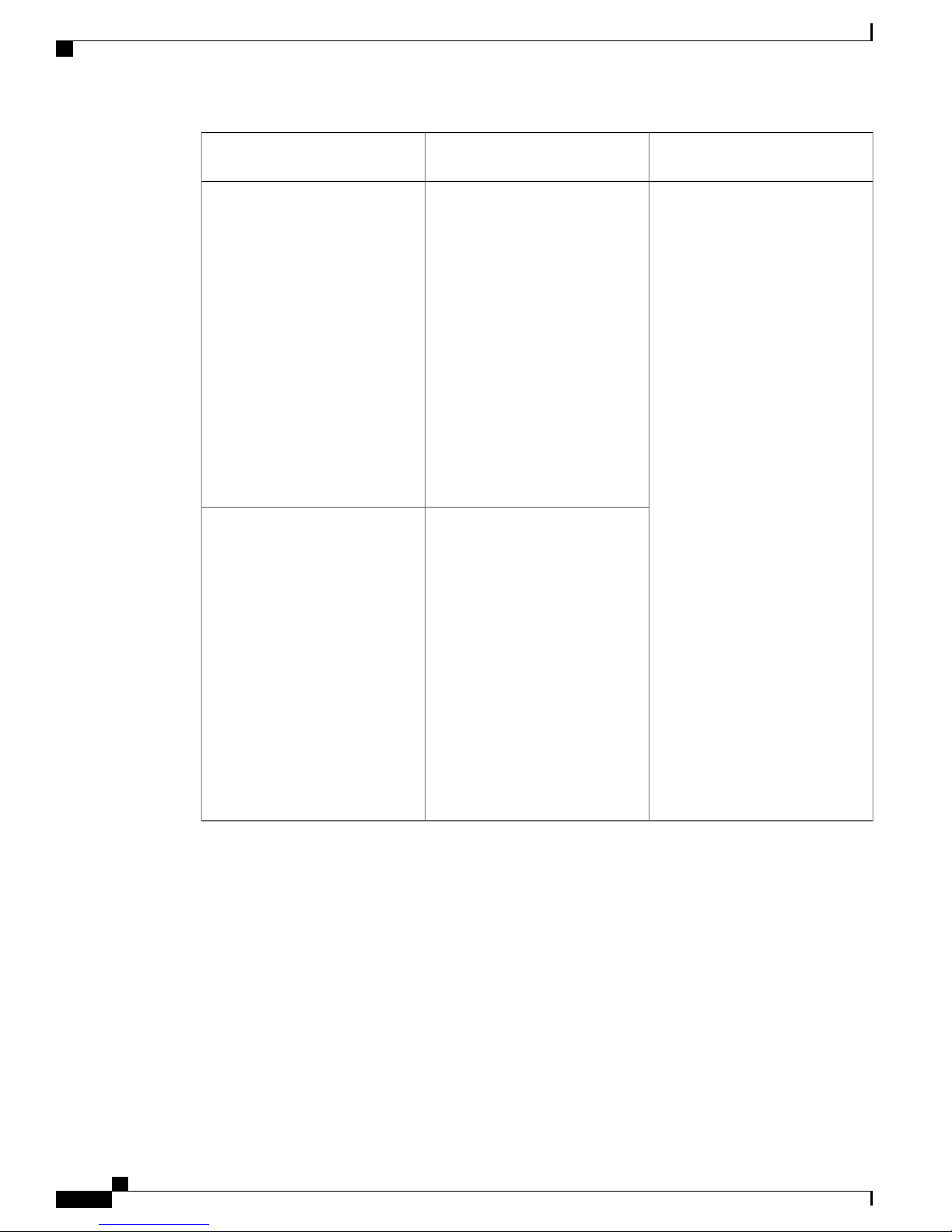
The following table describes the hardware specifications of Cisco SNS 3415 and Cisco SNS 3495 appliances.
Cisco SNS-3400 Series Appliance Hardware Installation Guide
1
Page 6
LED Indicators on Cisco SNS-3415 and 3495 Appliances
Appliance
Cisco SNS 3400 Series Appliance Overview
DiagramsHardware SpecificationsCisco Identity Services Engine
Cisco SNS-3415-K9
Cisco SNS-3495-K9
Cisco UCS C220 M3
•
Single socket Intel E5-2609
•
2.4Ghz CPU 4 total cores, 4
total threads
16 GB RAM
•
1 x 600-GB disk
•
Embedded Software RAID 0
•
4 GE network interfaces
•
For physical, environmental,
•
and power specifications, see
Server Specifications, on
page 15
Cisco UCS C220 M3
•
Dual socket Intel Xeon
•
E5-2609 2.4GHz CPU 8 total
cores, 8 total threads
32 GB RAM
2 x 600-GB disks
RAID 0+1
4 GE network interfaces
For physical, environmental,
and power specifications, see
Server Specifications, on
page 15.
Cisco SNS-3415 or 3495
Appliance Front Panel View, on
page 3
Cisco SNS 3415 or SNS 3495
Appliance Back Panel View , on
page 6
LED Indicators on Cisco SNS-3415 and 3495 Appliances
This section describes the front- and rear-panel controls, ports, and LED indicators on the Cisco SNS 3415
or Cisco SNS 3495 appliances.
Cisco SNS-3415 or 3495 Appliance Front Panel View, on page 3
•
Cisco SNS 3415 or SNS 3495 Appliance Back Panel View , on page 6
•
Cisco SNS-3400 Series Appliance Hardware Installation Guide
2
Page 7
Cisco SNS 3400 Series Appliance Overview
Cisco SNS-3415 or 3495 Appliance Front Panel View
Cisco SNS-3415 or 3495 Appliance Front Panel View
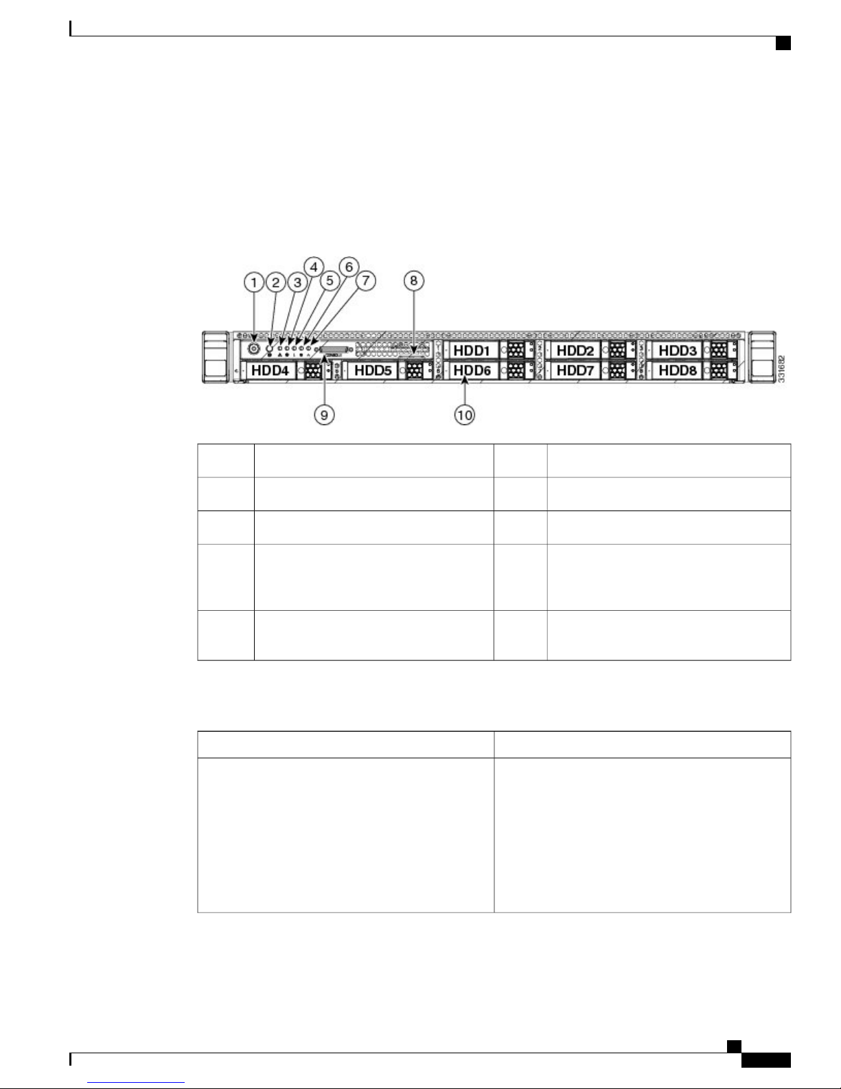
The following figure shows the components of the Cisco SNS-3415 or Cisco SNS-3495 appliance front panel
view.
Figure 1: Cisco SNS-3415/3495 Appliance Front View
Power supply status LED6Power button/Power status LED1
Network link activity LED7Identification button/LED2
Asset tag (serial number)8System status LED3
9Fan status LED4
9 KVM connector (used with KVM cable
that provides two USB, one VGA, and one
serial connector)
10Temperature status LED5
Drives (up to eight hot-swappable 2-5-inch
drives)
The following table describes the LEDs located on the front panel of the Cisco SNS-3415 or Cisco SNS-3495
appliance.
StateFront Panel LED Names
Power button/Power status LED
• Off—There is no AC power to the server.
• Amber—The server is in standby power mode.
Power is supplied only to the Cisco IMC and
some motherboard functions.
• Green—The server is in main power mode.
Power is supplied to all server components.
Cisco SNS-3400 Series Appliance Hardware Installation Guide
3
Page 8

Cisco SNS-3415 or 3495 Appliance Front Panel View
Cisco SNS 3400 Series Appliance Overview
StateFront Panel LED Names
Identification
System status
• Off—The identification LED is not in use.
• Blue—The identification LED is activated.
• Green—The server is running in normal
operating condition.
• Green, blinking—The server is performing
system initialization and memory check.
• Amber, steady—The server is in a degraded
operational state. For example:
Power supply redundancy is lost.
◦
CPUs are mismatched.
◦
At least one CPU is faulty.
◦
At least one DIMM is faulty.
◦
At least one drive in a RAID configuration
◦
failed.
• Amber, blinking—The server is in a critical
fault state. For example:
Fan status
Temperature status
Boot failed.
◦
Fatal CPU and/or bus error is detected.
◦
Server is in an over-temperature condition.
◦
• Green—All fan modules are operating properly.
• Amber, steady—One or more fan modules
breached the critical threshold.
• Amber, blinking—One or more fan modules
breached the non-recoverable threshold.
• Green—The server is operating at normal
temperature.
• Amber, steady—One or more temperature
sensors breached the critical threshold.
• Amber, blinking—One or more temperature
sensors breached the non-recoverable threshold.
Cisco SNS-3400 Series Appliance Hardware Installation Guide
4
Page 9
Cisco SNS 3400 Series Appliance Overview
Cisco SNS-3415 or 3495 Appliance Front Panel View
StateFront Panel LED Names
Power supply status
Network link activity
Hard drive fault
Hard drive activity
• Green—All power supplies are operating
normally.
• Amber, steady—One or more power supplies
are in a degraded operational state.
• Amber, blinking—One or more power supplies
are in a critical fault state.
• Off—The Ethernet link is idle.
• Green—One or more Ethernet LOM ports are
link-active, but there is no activity.
• Green, blinking—One or more Ethernet LOM
ports are link-active, with activity.
• Off—The hard drive is operating properly.
• Amber—Drive fault detected.
• Amber, blinking—The device is rebuilding.
• Off—There is no hard drive in the hard drive
tray (no access, no fault).
• Green—The hard drive is ready.
• Green, blinking—The hard drive is reading or
writing data.
Cisco SNS-3400 Series Appliance Hardware Installation Guide
5
Page 10
Cisco SNS 3400 Series Appliance Overview
Cisco SNS 3415 or SNS 3495 Appliance Back Panel View
Cisco SNS 3415 or SNS 3495 Appliance Back Panel View
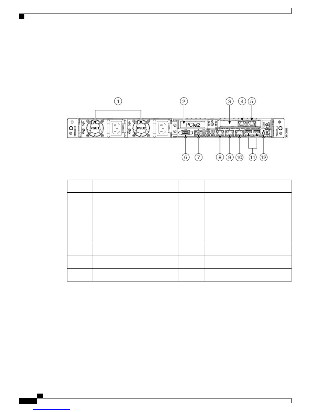
The following figure shows the components of the Cisco SNS-3415 and Cisco 3495 appliance back panel
view.
Figure 2: Cisco SNS-3415/3495 Appliance Rear View
Table 1:
Serial port (RJ-45 connector)7Power supplies (up to two)1
2
8Slot 2: Low-profile Peripheral
Component Interconnect Express (PCIe)
1-GB Ethernet dedicated management
port used to access CIMC (labeled M)
slot on riser (half-height, half-length, x16
connector, x16 lane width)
3
9Slot 1: PCIe1 card containing 1-GB
Ethernet ports (GigE2 and GigE3)
1-GB Ethernet port 1 (GigE0) for Cisco
ISE management communication
1-GB Ethernet port 2 (GigE1)101-GB Ethernet port 3 (GigE2)4
USB Ports111-GB Ethernet port 4 (GigE3)5
Rear identification button12VGA video connector6
The following table describes the LEDs located on the back panel of the Cisco SNS-3415 or Cisco SNS-3495
appliance.
Cisco SNS-3400 Series Appliance Hardware Installation Guide
6
Page 11
Cisco SNS 3400 Series Appliance Overview
Cisco SNS 3415 or SNS 3495 Appliance Back Panel View
StateLED Name
Power supply fault
Power supply AC OK
1-GbE Ethernet dedicated management link speed
• Off—The power supply is operating normally.
• Amber, blinking—An event warning threshold
has been reached, but the power supply
continues to operate.
• Amber, solid—A critical fault threshold has
been reached, causing the power supply to shut
down (for example, a fan failure or an
over-temperature condition).
• Off—There is no AC power to the power
supply.
• Green, blinking—AC power OK, DC output
not enabled.
• Green, solid—AC power OK, DC outputs OK.
• Off—link speed is 10 Mbps.
• Amber—link speed is 100 Mbps.
• Green—link speed is 1 Gbps.
1-GbE Ethernet dedicated management link status
1-GbE Ethernet link speed
1-GbE Ethernet link status
• Off—No link is present.
• Green—Link is active.
• Green, blinking—Traffic is present on the active
link.
• Off—link speed is 10 Mbps.
• Amber—link speed is 100 Mbps.
• Green—link speed is 1 Gbps.
• Off—No link is present.
• Green—Link is active.
• Green, blinking—Traffic is present on the active
link.
Cisco SNS-3400 Series Appliance Hardware Installation Guide
7
Page 12

Internal Diagnostic LEDs
Cisco SNS 3400 Series Appliance Overview
StateLED Name
Identification
Internal Diagnostic LEDs
The server has internal fault LEDs for fan modules and DIMMs. The LED lights amber to indicate a failed
component.
Power must be connected to the server for these LEDs to be operational.Note
The following figure shows the locations of these internal LEDs in Cisco SNS-3415 or Cisco SNS-3495
appliance.
• Off—The Identification LED is not in use.
• Blue—The Identification LED is activated.
The following table describes the callouts in the above figure.
1
fan connector on the motherboard)
Cisco SNS-3400 Series Appliance Hardware Installation Guide
8
2Fan module fault LEDs (one next to each
DIMM fault LEDs (one next to each
DIMM socket on the motherboard)
Page 13

Cisco SNS 3400 Series Appliance Overview
The following table describes the internal diagnostic LEDs located inside the Cisco SNS-3400 series appliance.
Regulatory Compliance
StateLED Name
Internal diagnostic LEDs (all)
Regulatory Compliance
For regulatory compliance and safety information, see Regulatory Compliance and Safety Information for
Cisco SNS-3415, Cisco SNS-3495, Cisco SNS-3515, and Cisco SNS-3595 Appliances.
• Off—Component is functioning normally.
• Amber—Component has failed.
Cisco SNS-3400 Series Appliance Hardware Installation Guide
9
Page 14

Regulatory Compliance
Cisco SNS 3400 Series Appliance Overview
Cisco SNS-3400 Series Appliance Hardware Installation Guide
10
Page 15

Before You Begin
This section provides information on how you can prepare your site for safely installing the Cisco SNS-3415
or Cisco SNS-3495 appliance.
Safety Guidelines, page 11
•
Unpack and Inspect the Server, page 12
•
Prepare for Server Installation, page 13
•
Server Specifications, page 15
•
Safety Guidelines
CHAPTER 2
Note
Warning
Warning
Before you install, operate, or service a Cisco SNS-3415 or Cisco SNS-3495 appliance, review the
Regulatory Compliance and Safety Information for Cisco SNS-3415, Cisco SNS-3495, Cisco SNS-3515,
and Cisco SNS-3595 Appliances for important safety information.
Warning: IMPORTANT SAFETY INSTRUCTIONS
This warning symbol means danger. You are in a situation that could cause bodily injury. Before you
work on any equipment, be aware of the hazards involved with electrical circuitry and be familiar with
standard practices for preventing accidents. Use the statement number provided at the end of each warning
to locate its translation in the translated safety warnings that accompanied this device.
Statement 1071
Warning: To prevent the system from overheating, do not operate it in an area that exceeds the maximum
recommended ambient temperature of: 40° C (104° F).
Statement 1047
Cisco SNS-3400 Series Appliance Hardware Installation Guide
11
Page 16

Unpack and Inspect the Server
Before You Begin
Warning
Warning
Warning
Warning: The plug-socket combination must be accessible at all times, because it serves as the main
disconnecting device.
Statement 1019
This product relies on the building’s installation for short-circuit (overcurrent) protection. Ensure that the
protective device is rated not greater than: 250 V, 15 A.
Statement 1005
Installation of the equipment must comply with local and national electrical codes.
Statement 1074
When you are installing a server, use the following guidelines:
Plan your site configuration and prepare the site before installing the server. See the Cisco UCS Site
•
Preparation Guide for the recommended site planning tasks.
Ensure that there is adequate space around the server to allow for servicing the server and for adequate
•
airflow. The airflow in this server is from front to back.
Ensure that the air-conditioning meets the thermal requirements listed in the Server Specifications, on
•
page 15.
Ensure that the cabinet or rack meets the requirements listed in the Rack Requirements, on page 15.
•
Ensure that the site power meets the power requirements listed in the Power Specifications, on page
•
16. If available, you can use an uninterruptible power supply (UPS) to protect against power failures.
Caution
Avoid UPS types that use ferroresonant technology. These UPS types can become unstable with systems
such as the Cisco UCS, which can have substantial current draw fluctuations from fluctuating data traffic
patterns.
Unpack and Inspect the Server
Caution
When handling internal server components, wear an ESD strap and handle modules by the carrier edges
only.
Keep the shipping container in case the server requires shipping in the future.Note
Cisco SNS-3400 Series Appliance Hardware Installation Guide
12
Page 17

Before You Begin
Prepare for Server Installation
Step 1
Step 2
Step 3
Note
The chassis is thoroughly inspected before shipment. If any damage occurred during transportation or any
items are missing, contact your customer service representative immediately.
To inspect the shipment:
Remove the server from its cardboard container and save all packaging material.
Compare the shipment to the equipment list provided by your customer service representative and the list given below.
Verify that you have all items.
Check for damage and report any discrepancies or damage to your customer service representative. Have the following
information ready:
Invoice number of shipper (see the packing slip)
•
Model and serial number of the damaged unit
•
Description of damage
•
Effect of damage on the installation
•
Figure 3: Shipping Box Contents
Prepare for Server Installation
Installation Guidelines, on page 14
•
Rack Requirements, on page 15
•
Equipment Requirements, on page 15
•
Cisco SNS-3400 Series Appliance Hardware Installation Guide
13
Page 18

Installation Guidelines
Slide Rail Adjustment Range, on page 15
•
Installation Guidelines
Before You Begin
Warning
Warning
Warning
Warning
Caution
Warning: To prevent the system from overheating, do not operate it in an area that exceeds the maximum
recommended ambient temperature of: 40° C (104° F).
Statement 1047
Warning: The plug-socket combination must be accessible at all times, because it serves as the main
disconnecting device.
Statement 1019
This product relies on the building’s installation for short-circuit (overcurrent) protection. Ensure that the
protective device is rated not greater than: 250 V, 15 A.
Statement 1005
Installation of the equipment must comply with local and national electrical codes.
Statement 1074
Avoid UPS types that use ferroresonant technology. These UPS types can become unstable with systems
such as the Cisco UCS, which can have substantial current draw fluctuations from fluctuating data traffic
patterns.
When you are installing a server, use the following guidelines
Plan your site configuration and prepare the site before installing the server. See the Cisco UCS Site
•
Preparation Guide for the recommended site planning tasks.
Ensure that there is adequate space around the server to allow for servicing the server and for adequate
•
airflow. The airflow in this server is from front to back.
Ensure that the air-conditioning meets the thermal requirements listed in the Server Specifications, on
•
page 15.
Ensure that the cabinet or rack meets the requirements listed in the Rack Requirements, on page 15.
•
Ensure that the site power meets the power requirements listed in the Power Specifications, on page
•
16. If available, you can use an uninterruptible power supply (UPS) to protect against power failures.
Cisco SNS-3400 Series Appliance Hardware Installation Guide
14
Page 19

Before You Begin
Rack Requirements
This section provides the requirements for the standard open racks.
The rack must be of the following type:
A standard 19-in. (48.3-cm) wide, four-post EIA rack, with mounting posts that conform to English
•
universal hole spacing, per section 1 of ANSI/EIA-310-D-1992.
The rack post holes can be square 0.38-inch (9.6 mm), round 0.28-inch (7.1 mm), #12-24 UNC, or
•
#10-32 UNC when you use the supplied slide rails.
The minimum vertical rack space per server must be one RU, equal to 1.75 in. (44.45 mm).
•
Equipment Requirements
The slide rails supplied by Cisco Systems for this server do not require tools for installation. The inner rails
(mounting brackets) are pre-attached to the sides of the server.
Rack Requirements
Slide Rail Adjustment Range
The slide rails for this server have an adjustment range of 24 to 36 inches (610 to 914 mm).
Server Specifications
This section lists the technical specifications for the server:
Physical Specifications
The following table lists the physical specifications of the server.
Table 2: Physical Specifications
SpecificationDescription
1.7 in. (4.3 cm)Height
16.9 in. (42.9 cm)Width
28.5 in. (72.4 cm)Depth
35.6 lb. (16.1 Kg)Weight (fully loaded chasis)
Cisco SNS-3400 Series Appliance Hardware Installation Guide
15
Page 20

Environmental Specifications
Environmental Specifications
The following table lists the environmental specifications of the server.
Table 3: Environmental Specifications
Before You Begin
SpecificationDescription
Temperature, operating
Measure A-weighted per ISO7779 LwAd (Bels)
Operation at 73°F (23°C)
Measure A-weighted per ISO7779 LpAm (dBA)
Operation at 73°F (23°C)
41 to 104°F (5 to 40°C)
Derate the maximum temperature by 1°C per every
305 meters of altitude above sea level.
-40 to 149°F (-40 to 65°C)Temperature, non-operating
10 to 90%Humidity (RH), noncondensing
0 to 10,000 feetAltitude, operating
0 to 40,000 feetAltitude, non-operating
5.4Sound power level
37Sound pressure level
Power Specifications
The power specifications are listed in the following section:
650-Watt Power Supply
Note
Cisco SNS-3400 Series Appliance Hardware Installation Guide
16
You can get more specific power information for your exact server configuration by using the Cisco UCS
Power Calculator.
Do not mix power supply types in the server. Both power supplies must be either 650W.Note
Page 21

Before You Begin
Power Specifications
Table 4: Cisco SNS-3400 Series Server 650-Watt Power Supply Specifications
SpecificationDescription
90 to 264 VAC (self-ranging, 180 to 264 VAC nominal)AC input voltage range
Range: 47 to 63 Hz (single phase, 50 to 60Hz nominal)AC input frequency
AC line input current (steady state)
Power supply output voltage
7.6 A peak at 100 VAC 3.65 A peak at 208 VAC
650 WattsMaximum output power for each power supply
Main power: 12 VDC
Standby power: 12 VDC
Cisco SNS-3400 Series Appliance Hardware Installation Guide
17
Page 22

Power Specifications
Before You Begin
Cisco SNS-3400 Series Appliance Hardware Installation Guide
18
Page 23

CHAPTER 3
Install the Cisco SNS 3415 and Cisco SNS 3495
Hardware Appliances
Install the Cisco SNS 3415 and Cisco SNS 3495 Hardware Appliances, page 19
•
Install the Cisco SNS 3415 or 3495 Appliance in a Rack, page 20
•
Connect Cables, page 24
•
Connect and Power On the Cisco SNS 3415 or 3495 Appliance, page 26
•
Cisco Integrated Management Controller, page 30
•
Install the Cisco SNS 3415 and Cisco SNS 3495 Hardware
Appliances
Warning
This section describes how to install your Cisco SNS 3415 or 3495 appliance and connect it to the network.
It contains:
Install the Cisco SNS 3415 or 3495 Appliance in a Rack, on page 20
•
Cisco Integrated Management Controller, on page 30
•
Connect Cables, on page 24
•
Cable Management, on page 26
•
Before you begin the installation, read the Regulatory Compliance and Safety Information for Cisco SNS-3415,
Cisco SNS-3495, Cisco SNS-3515, and Cisco SNS-3595 Appliances.
Warning: Only trained and qualified personnel should be allowed to install, replace, or service this
equipment.
Statement 1030
Cisco SNS-3400 Series Appliance Hardware Installation Guide
19
Page 24

Install the Cisco SNS 3415 or 3495 Appliance in a Rack
Install the Cisco SNS 3415 and Cisco SNS 3495 Hardware Appliances
Warning
Warning: This unit is intended for installation in restricted access areas. A restricted access area can be
accessed only through the use of a special tool, lock and key, or other means of security.
Statement 1017
Install the Cisco SNS 3415 or 3495 Appliance in a Rack
This section describes how to install the Cisco SNS 3415 or Cisco SNS 3495 appliance in a rack.
Install the Side Rails
Warning
To prevent bodily injury when mounting or servicing this unit in a rack, you must take special precautions
to ensure that the system remains stable. The following guidelines are provided to ensure your safety:
This unit should be mounted at the bottom of the rack if it is the only unit in the rack.
When mounting this unit in a partially filled rack, load the rack from the bottom to the top with the heaviest
component at the bottom of the rack.
If the rack is provided with stabilizing devices, install the stabilizers before mounting or servicing the unit
in the rack.
Statement 1006
Step 1
Open the front securing latch (see the following figure). The end of the slide-rail assembly marked “FRONT” has a
spring-loaded securing latch that must be open before you can insert the mounting pegs into the rack-post holes.
a)
On the rear side of the securing-latch assembly, hold open the clip marked “PULL.”
b) Slide the spring-loaded securing latch away from the mounting pegs.
Cisco SNS-3400 Series Appliance Hardware Installation Guide
20
Page 25

Install the Cisco SNS 3415 and Cisco SNS 3495 Hardware Appliances
c)
Release the clip marked “PULL” to lock the securing latch in the open position.
Figure 4: Front Securing Latch
Install the Side Rails
1
Clip marked “PULL” on rear of assembly
Front mounting pegs2
Step 2
Install the slide rails onto the rack:
a) Position a slide-rail assembly inside the two left-side rack posts (see the following figure).
Use the “FRONT” and “REAR” markings on the slide-rail assembly to orient the assembly correctly with the front
and rear rack posts.
b) Position the front mounting pegs so that they enter the desired front rack-post holes from the front.
Spring-loaded securing latch on front of assembly3
Cisco SNS-3400 Series Appliance Hardware Installation Guide
21
Page 26

Install the Side Rails
Install the Cisco SNS 3415 and Cisco SNS 3495 Hardware Appliances
Note
The mounting pegs that protrude through the rack-post holes are designed to fit round or square holes, or
smaller #10-32 round holes when the mounting peg is compressed. If your rack has #10-32 rack-post holes,
align the mounting pegs with the holes and then compress the spring-loaded pegs to expose the #10-32 inner
peg.
c) Expand the length-adjustment bracket until the rear mounting pegs protrude through the desired holes in the rear rack
post.
Use your finger to hold the rear securing latch open when you insert the rear mounting pegs to their holes. When you
release the latch, it wraps around the rack post and secures the slide-rail assembly.
Figure 5: Attaching a Slide Rail Assembly
Step 3
Length-adjustment bracket4Front-left rack post1
Rear mounting pegs5Front mounting pegs2
Rear securing latch6Slide-rail assembly3
d) Attach the second slide-rail assembly to the opposite side of the rack. Ensure that the two slide-rail assemblies are
level and at the same height with each other.
e) Pull the inner slide rails on each assembly out toward the rack front until they hit the internal stops and lock in place.
Insert the server into the slide rails:
Note
The inner rails are pre-attached to the sides of the server at the factory. You can order replacement inner rails
if these are damaged or lost (Cisco PID UCSC-RAIL1-I).
a) Align the inner rails that are pre-attached to the server sides with the front ends of the empty slide rails.
b) Push the server into the slide rails until it stops at the internal stops.
Cisco SNS-3400 Series Appliance Hardware Installation Guide
22
Page 27

Install the Cisco SNS 3415 and Cisco SNS 3495 Hardware Appliances
c) Push in the plastic release clip on each inner rail (labelled PUSH), and then continue pushing the server into the rack
until its front latches engage the rack posts.
Install the Cable Management Arm (Optional)
Step 4
(Optional) Attach the cable management arm (CMA) to the rear of the slide rails. See Install the Cable Management
Arm (Optional), on page 23 for information.
Step 5
Continue with the “Connecting and Powering on Cisco SNS-3415/3495 Appliance”.
Install the Cable Management Arm (Optional)
You can attach the cable management arm (CMA) to the rear of the slide rails.
The CMA is designed for mounting on either the right or left slide rails. These instructions describe an
installation to the rear of the right slide rails, as viewed from the rear of server.
Note: Whether you are mounting the CMA to the left or right slide rails, be sure to orient the engraved marking,
“UP” so that it is always on the upper side of the CMA. See the following figure.
Step 1
Step 2
Step 3
Note
With the server pushed fully into the rack, slide the plastic clip on the inner CMA arm over the flange on the mounting
bracket that attached to the side of the server. See the following figure.
Note
Slide the plastic clip on the outer CMA arm over the flange on the slide rail. See the following figure.
Attach the CMA retaining bracket to the left slide rail. Slide the plastic clip on the bracket over the flange on the end of
the left slide.
Figure 6: Attaching the Cable Management Arm (Rear of Server Shown)
Cisco SNS-3400 Series Appliance Hardware Installation Guide
23
Page 28

Connect Cables
Flange on rear of outer right slide rail4
Connect Cables
This section describes how to connect your Cisco SNS-3415 or Cisco SNS-3495 appliance to the network
and the appliance console.
Install the Cisco SNS 3415 and Cisco SNS 3495 Hardware Appliances
Inner CMA arm attachment clip5Flange on rear of outer left slide rail1
6CMA retaining bracket2
“UP” orientation marking
Outer CMA arm attachment clip7Flange on rear of right mounting bracket3
Connect the Network Interface, on page 24
•
Connect the Console, on page 25
•
Connect the Keyboard and Video Monitor, on page 25
•
Cable Management, on page 26
•
Attach cables (such as keyboard, monitor cables, if required) to the rear of the server. Route the cables properly
and use the cable straps to secure the cables to the slide rails. See the Cisco SNS 3415 or SNS 3495 Appliance
Back Panel View , on page 6 for reference on the rear view of the appliance.
Connect the Network Interface
Warning
Warning: Do not work on the system or connect or disconnect cables during periods of lightning activity.
Statement 1001
This section describes how to connect the Cisco SNS-3415 or Cisco SNS-3495 appliance Ethernet port.
The Ethernet connector supports Serial over LAN (SOL) cables. The RJ-45 port supports standard
straight-through and crossover Category 5 unshielded twisted-pair (UTP) cables. Cisco does not supply
Category 5 UTP cables; these cables are available commercially.
Cisco SNS-3400 Series Appliance Hardware Installation Guide
24
Page 29

Install the Cisco SNS 3415 and Cisco SNS 3495 Hardware Appliances
To connect the cable to the appliance Ethernet port:
Connect the Console
Step 1
Step 2
Step 3
Verify that the appliance is turned off.
Connect one end of the cable to the GigabitEthernet 0 port on the appliance.
Connect the other end to a switch in your network.
Connect the Console
Warning
Warning: Do not work on the system or connect or disconnect cables during periods of lightning activity.
Statement 1001
Your Cisco SNS-3415 or Cisco SNS-3495 appliance has a DCE-mode console port for connecting a console
terminal to your appliance. The appliance uses a DB-9 serial connector for the console port.
The console port on the Cisco SNS-3415 or Cisco SNS-3495 appliance includes an EIA/TIA-232 asynchronous
serial (DB-9) connector. This serial console connector (port) allows you to access the appliance locally by
connecting a terminal—either a PC running terminal-emulation software or an ASCII terminal—to the console
port.
To connect a PC running terminal-emulation software to the console port, use a DB-9 female to DB-9 female
straight-through cable.
To connect an ASCII terminal to the console port, use a DB-9 female to DB-25 male straight-through cable
with a DB-25 female to DB-25 female gender changer.
To connect a terminal or a PC running terminal-emulation software to the console port on the Cisco SNS-3415
or Cisco SNS-3495 appliance:
Step 1
Step 2
Connect the terminal using a straight-through cable to the console port.
Configure your terminal or terminal-emulation software for 9600 baud, 8 data bits, no parity, 1 stop bit, and no hardware
flow control.
Connect the Keyboard and Video Monitor
Warning
Do not work on the system or connect or disconnect cables during periods of lightning activity.
Statement 1001
This section describes how to connect a keyboard and video monitor to the Cisco SNS-3415 or Cisco SNS-3495
appliance.
Cisco SNS-3400 Series Appliance Hardware Installation Guide
25
Page 30

Cable Management
Install the Cisco SNS 3415 and Cisco SNS 3495 Hardware Appliances
You can connect the keyboard and video monitor to the Cisco SNS-3415 or Cisco SNS-3495 appliance using
the KVM connector available in the front panel of the Cisco SNS-3415 or Cisco SNS-3495 appliance. A KVM
cable is shipped along with the appliance that provides two USB, one VGA, and one serial connector.
The Cisco SNS-3415 or Cisco SNS-3495 appliance does not provide support for a mouse.
The Cisco SNS-3415 or Cisco SNS-3495 provides USB ports on the rear of the appliance that can be used to
connect a keyboard and video monitor.
To connect a keyboard and video monitor to the appliance:
Step 1
Step 2
Step 3
Step 4
Verify that the appliance is turned off.
Connect the end of the keyboard cable to the PS/2 (keyboard) port which is located on the back panel of the appliance.
Connect the end of the video monitor cable to the PS/2 (video monitor) port which is located on the back panel of the
appliance.
Power on the appliance.
Cable Management
Cable management is the most visual aspect of your appliance setup. However, cable management is often
overlooked because it can be time consuming.
Equipment racks and enclosures house more equipment today than ever before. This growth has increased
the need for organized cable management both inside and outside the rack. Poor cable management not only
leads to damaged cables or increased time for adding or changing cables, but also blocks critical airflow or
access. These problems can lead to inefficiencies in the performance of your equipment or even downtime.
There are many solutions to address cable management. They can range from simple cable management rings,
to vertical or horizontal organizers, to troughs and ladders.
All Cisco SNS-3415 or Cisco SNS-3495 appliance cables should be properly dressed so as not to interfere
with each other or other pieces of equipment. Use local practices to ensure that the cables attached to your
appliance are properly dressed.
Proceed to the next section, Connect and Power On the Cisco SNS 3415 or 3495 Appliance, on page 26, to
continue the installation process.
Connect and Power On the Cisco SNS 3415 or 3495 Appliance
Connect and Power On the Server (Standalone Mode), on page 27
•
NIC Modes and NIC Redundancy Settings, on page 28
•
System BIOS and CIMC Firmware, on page 29
•
Cisco SNS-3400 Series Appliance Hardware Installation Guide
26
Page 31

Install the Cisco SNS 3415 and Cisco SNS 3495 Hardware Appliances
Connect and Power On the Server (Standalone Mode)
Connect and Power On the Server (Standalone Mode)
Step 1
Note
This section describes how to power on the server, assign an IP address, and connect to server management
when using the server in standalone mode. To use the server in UCS integration, specific cabling and
settings are required. See Installation for Cisco UCS Integration.
Note
The server is shipped with a default NIC mode called Shared LOM, default NIC redundancy is active-active,
and DHCP is enabled. Shared LOM mode enables the two 1-Gb Ethernet ports to access the Cisco Integrated
Management Interface (CIMC). If you want to use the 1-Gb Ethernet dedicated management port, or a
port on a Cisco UCS P81E Virtual Interface Card (VIC) to access the CIMC, you must first connect to
the server and change the NIC mode as described in Step 3 of the following procedure. In that step, you
can also change the NIC redundancy and set static IP settings.
Attach a power cord to each power supply unit in your server, and then attach each power cord to a grounded AC power
outlet. See Power Specifications, on page 16 for power specifications. Wait for approximately two minutesto let the
server boot in standby power during the first bootup.
You can verify power status by looking at the Power Status LED (see LED Indicators on Cisco SNS-3415 and 3495
Appliances, on page 2):
• Of—There is no AC power present in the server.
• Amber—The server is in standby power mode. Power is supplied only to the CIMC and some motherboard functions.
Step 2
Step 3
Step 4
Step 5
• Green—The server is in main power mode. Power is supplied to all server components.
Note
During bootup, the server beeps once for each USB device that is attached to the server. Even if there are no
external USB devices attached, there is a short beep for each virtual USB device such as a virtual floppy drive,
CD/DVD drive, keyboard, or mouse. A beep is also emitted if a USB device is hot-plugged or hot-unplugged
during BIOS power-on self test (POST), or while you are accessing the BIOS Setup utility or the EFI shell.
Connect a USB keyboard and VGA monitor by using the supplied KVM cable connected to the KVM connector on the
front panel (see Cisco SNS-3415 or 3495 Appliance Front Panel View, on page 3).
Note
Alternatively, you can use the VGA and USB ports on the rear panel. However, you cannot use the front panel
VGA and the rear panel VGA at the same time. If you are connected to one VGA connector and you then connect
a video device to the other connector, the first VGA connector is disabled.
See Setup CIMC Configuration Utility, on page 30 to enter in to the BIOS CIMC Configuration Utility. Use this utility
to set NIC mode, NIC redundancy, and choose whether to enable DHCP or set static network settings.
Connect to the CIMC for server management. Connect Ethernet cables from your LAN to the server, using the ports that
you selected in Step 3. The Active-active and Active-passive NIC redundancy settings require you to connect to two
ports.
Enter the IP address of the CIMC in your browser to connect to the CIMC Setup Utility. The CIMC IP address is
configured in Step 3 (either a static address or the address assigned by your DHCP server).
Cisco SNS-3400 Series Appliance Hardware Installation Guide
27
Page 32

NIC Modes and NIC Redundancy Settings
To manage the server, see the Cisco UCS C-Series Rack-Mount Server Configuration Guide or the Cisco
UCS C-Series Rack-Mount Server CLI Configuration Guide for instructions on using those interfaces. The
links to these documents are in the C-Series documentation roadmap:
http://www.cisco.com/go/unifiedcomputing/c-series-doc
NIC Modes and NIC Redundancy Settings
NIC Modes
This server has the following NIC mode settings that you can choose from:
• Shared LOM EXT (default)—This is the Shared LOM extended mode, the factory-default setting. With
this mode, the shared LOM and Cisco Card interfaces are both enabled.
In this mode, DHCP replies are returned to both the shared LOM ports and the Cisco card ports. If the
system determines that the Cisco card connection is not getting its IP address from a Cisco UCS Manager
system because the server is in standalone mode, further DHCP requests from the Cisco card are disabled.
If the system determines that the Cisco card connection is getting its IP address from a Cisco UCS
Manager system, the reply has parameters that automatically move the server to UCSM mode.
Install the Cisco SNS 3415 and Cisco SNS 3495 Hardware Appliances
• Dedicated—The dedicated management port is used to access Cisco IMC. You must select a NIC
redundancy and IP setting.
• Shared LOM—The 1-Gb Ethernet ports are used to access Cisco IMC. You must select a NIC redundancy
and IP setting.
• Cisco Card—The ports on an installed Cisco UCS virtual interface card (VIC) are used to access Cisco
IMC. You must select a NIC redundancy and IP setting.
See also the required VIC Slot setting below.
• VIC Slot—If you use the Cisco Card NIC mode, you select this setting to match where your VIC is
installed. The choices are Riser1, Riser2, or Flex-LOM (the mLOM slot).
If you select Riser1, slot 1 is used.
◦
If you select Riser2, slot 2 is used.
◦
If you select Flex-LOM, you must use an mLOM-style VIC in the mLOM sl
◦
NIC Redundancy
This server has the following NIC redundancy settings that you can choose from:
• None—The Ethernet ports operate independently and do not fail over if there is a problem. This setting
can be used only with the Dedicated NIC mode.
• Active-standby—If an active Ethernet port fails, traffic fails over to a standby port.
• Active-active—All Ethernet ports are utilized simultaneously. Shared LOM EXT mode can have only
this NIC redundancy setting. Shared LOM and Cisco Card modes can have both Active-standby and
Active-active settings.
The active/active setting uses Mode 5 or Balance-TLB (adaptive transmit load balancing). This is channel
bonding that does not require any special switch support. The outgoing traffic is distributed according
Cisco SNS-3400 Series Appliance Hardware Installation Guide
28
Page 33

Install the Cisco SNS 3415 and Cisco SNS 3495 Hardware Appliances
to the current load (computed relative to the speed) on each slave. Incoming traffic is received by the
current slave. If the receiving slave fails, another slave takes over the MAC address of the failed receiving
slave.
System BIOS and CIMC Firmware
This section includes information about the system BIOS 1.4.7b.0, and it includes the following sections:
Update the BIOS and Cisco IMC Firmware, on page 29
•
Access the System BIOS, on page 30
•
Update the BIOS and Cisco IMC Firmware
System BIOS and CIMC Firmware
Caution
Note
When you upgrade the BIOS firmware, you must also upgrade the CIMC firmware to the same version
or the server will not boot. Do not power off the server until the BIOS and CIMC firmware are matching
or the server will not boot.
Cisco provides the Cisco Host Upgrade Utility to assist with simultaneously upgrading the BIOS, CIMC,
and other firmware to compatible levels.
The server uses firmware obtained from and certified by Cisco. Cisco provides release notes with each firmware
image. There are several methods for updating the firmware:
Recommended method for systems running firmware level 1.2 or later: Use the Cisco Host Upgrade
•
Utility to simultaneously upgrade the CIMC, BIOS, LOM, LSI storage controller, and Cisco UCS P81E
VIC firmware to compatible levels.
Note
We recommend that you upgrade the CIMC/BIOS firmware to version 2.x or later. You
can download the firmware image from Cisco.com.
See the Cisco Host Upgrade Utility Quick Reference Guide for your firmware level at the documentation
roadmap link below.
Your system firmware must be at minimum level 1.2 to use the Cisco Host Upgrade Utility. If your
firmware is prior to level 1.2, you must use the methods below to update the BIOS and CIMC firmware
individually.
You can upgrade the BIOS using the EFI interface, or upgrade from a Windows or Linux platform. See
•
the Cisco UCS C-Series Rack-Mount Server BIOS Upgrade Guide.
You can upgrade the CIMC and BIOS firmware by using the CIMC GUI interface. See the Cisco UCS
•
C-Series Rack-Mount Server Configuration Guide.
You can upgrade the CIMC and BIOS firmware by using the CIMC CLI interface. See the Cisco UCS
•
C-Series Rack-Mount Server CLI Configuration Guide.
Cisco SNS-3400 Series Appliance Hardware Installation Guide
29
Page 34

Cisco Integrated Management Controller
For links to the documents listed above, see the documentation roadmap at the following URL:
http:// www.cisco.com/c/en/us/td/docs/unified_computing/ucs/overview/guide/UCS_rack_roadmap.html
Access the System BIOS
To change the BIOS settings for your server, follow these steps. Detailed instructions are also printed on the
BIOS screens.
Install the Cisco SNS 3415 and Cisco SNS 3495 Hardware Appliances
Step 1
Step 2
Step 3
Step 4
Step 5
Step 6
Enter the BIOS setup utility by pressing the F2 key when prompted during bootup.
The version and build of the current BIOS are displayed on the Main page of the utility.Note
Use the arrow keys to select the BIOS menu page.
Highlight the field to be modified by using the arrow keys.
Press Enter to select the field that you want to change, and then modify the value in the field.
Press the right arrow key until the Exit menu screen is displayed.
Follow the instructions on the Exit menu screen to save your changes and exit the setup utility (or Press F10). You can
exit without saving changes by pressing Esc.
Cisco Integrated Management Controller
You can monitor the server inventory, health, and system event logs by using the built-in Cisco Integrated
Management Controller (CIMC) GUI or CLI interfaces. See the user documentation for your firmware release
at the following URL:
http://www.cisco.com/c/en/us/support/servers-unified-computing/ucs-c-series-integrated-management-controller/
products-installation-and-configuration-guides-list.html
Setup CIMC Configuration Utility
You can perform all operations on the Cisco SNS-3415 or Cisco SNS-3495 appliance through the CIMC. To
do this, you must first configure an IP address and IP gateway to access the CIMC from a web-based browser.
Step 1
Step 2
30
Plug in the power cord.
Press the Power button to boot the server.
Cisco SNS-3400 Series Appliance Hardware Installation Guide
Page 35

Install the Cisco SNS 3415 and Cisco SNS 3495 Hardware Appliances
Setup CIMC Configuration Utility
Step 3
During bootup, press F8 when prompted to open the BIOS CIMC Configuration Utility. The following screen appears.
Cisco SNS-3400 Series Appliance Hardware Installation Guide
31
Page 36

Setup CIMC Configuration Utility
Install the Cisco SNS 3415 and Cisco SNS 3495 Hardware Appliances
Step 4
Step 5
Step 6
Step 7
Step 8
Step 9
Set the NIC mode to your choice for which ports to use to access the CIMC for server management (see Cisco SNS-3415
or 3495 Appliance Front Panel View, on page 3 for identification of the ports):
• Dedicated—The 1-Gb Ethernet management port is used to access the CIMC. You must select NIC redundancy
None and select IP settings.
• Shared LOM (default)—The two 1-Gb Ethernet ports are used to access the CIMC. This is the factory default
setting, along with Active-active NIC redundancy and DHCP enabled.
• Cisco Card—The ports on an installed Cisco UCS P81E VIC are used to access the CIMC. You must select a NIC
redundancy and IP setting.
Note
The Cisco Card NIC mode is currently supported only with a Cisco UCS P81E VIC (N2XX-ACPCI01) that is
installed in PCIe slot 1.
Use this utility to change the NIC redundancy to your preference. This server has three possible NIC redundancy settings:
• None—The Ethernet ports operate independently and do not fail over if there is a problem.
• Active-standby—If an active Ethernet port fails, traffic fails over to a standby port.
• Active-active—All Ethernet ports are utilized simultaneously.
Choose whether to enable DHCP for dynamic network settings, or to enter static network settings.
Note
Note: Before you enable DHCP, your DHCP server must be preconfigured with the range of MAC addresses
for this server. The MAC address is printed on a label on the rear of the server. This server has a range of six
MAC addresses assigned to the CIMC. The MAC address printed on the label is the beginning of the range of
six contiguous MAC addresses.
(Optional) Use this utility to make VLAN settings.
Use this utility to set a default CIMC user password.
Note
Changes to the settings take effect after approximately 45 seconds. Refresh with F5 and wait until the new
settings appear before you reboot the server in the next step.
Press F10 to save your settings and reboot the server.
Note
Note: If you chose to enable DHCP, the dynamically assigned IP and MAC addresses are displayed on the
console screen during bootup.
Note
By default, the baud rate of the serial port is set to 115200. After you configure CIMC, log in to the CIMC
user interface and change the serial port buad rate to 9600.
Cisco SNS-3400 Series Appliance Hardware Installation Guide
32
 Loading...